lte-advanced webcast 2011-06-02
DESCRIPTION
LTE-Advanced Webcast 2011-06-02TRANSCRIPT
Copyright © 2011 Agilent Technologies
2011 Greater insight.Greater confidence.
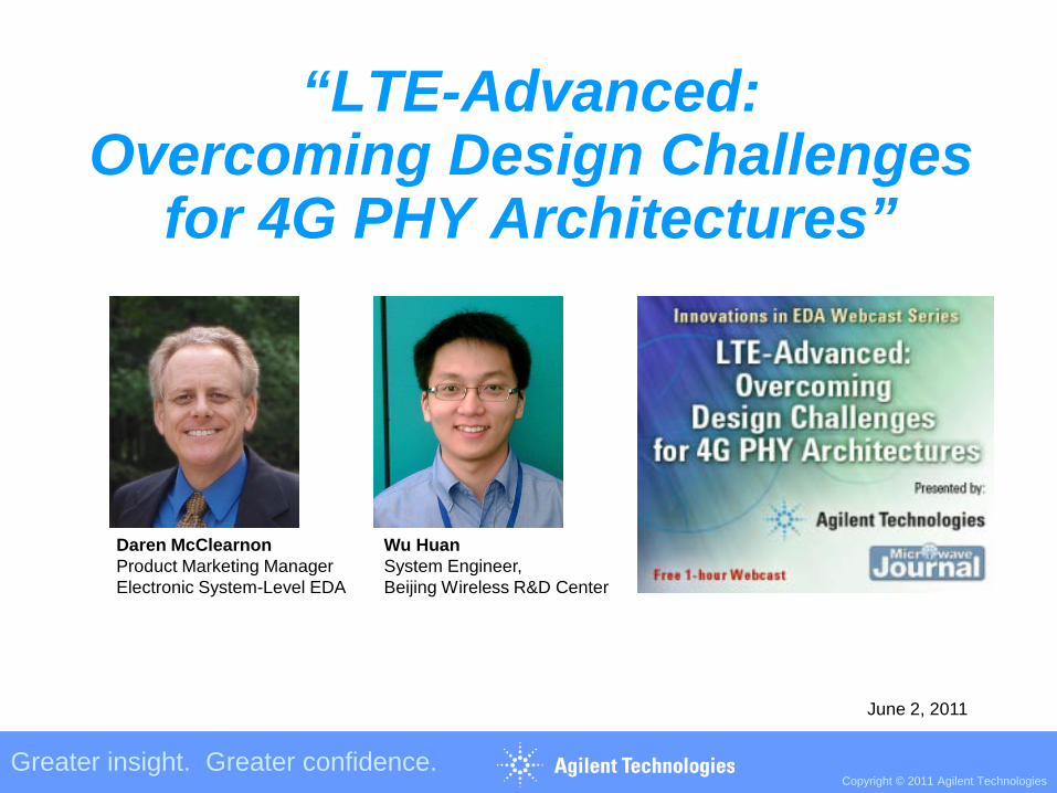
“LTE-Advanced:Overcoming Design Challenges
for 4G PHY Architectures”
Greater insight. Greater confidence.Copyright © 2011 Agilent Technologies
Daren McClearnonProduct Marketing ManagerElectronic System-Level EDA
Wu HuanSystem Engineer,Beijing Wireless R&D Center
June 2, 2011
Copyright © 2011 Agilent Technologies
2011 Greater insight.Greater confidence.
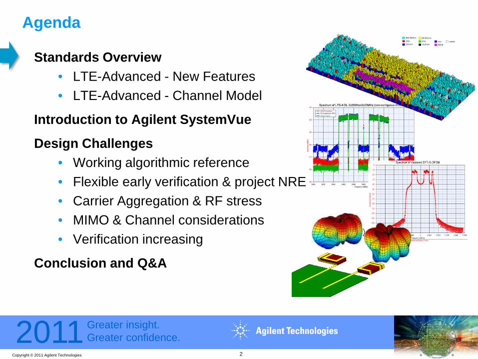
Agenda
Standards Overview• LTE-Advanced - New Features• LTE-Advanced - Channel Model
Introduction to Agilent SystemVue
Design Challenges• Working algorithmic reference• Flexible early verification & project NRE• Carrier Aggregation & RF stress• MIMO & Channel considerations• Verification increasing
Conclusion and Q&A
2

Copyright © 2011 Agilent Technologies
2011 Greater insight.Greater confidence.
LTE-Advanced Requirement
Performance indicators LTERelease 8
IMT-Advanced LTE-AdvancedRelease 10
Peak data rate DL 300 Mb/s 1Gb/s 1 Gb/sUL 75 Mb/s 500 Mb/s
Peak spectrum efficiency [bps/Hz]
DL 15 [bps/Hz] 15 [bps/Hz] 30 [bps/Hz]UL 3.75 [bps/Hz] 6.75 [bps/Hz] 15 [bps/Hz]
Control plane latency < 100 ms 100 ms < 50 msUser plane latency < 5 ms 10 ms < Rel – 8 LTEScalable bandwidth support Up to 20 MHz Up to 40 MHz Up to 100 MHzVoIP capacity 200 Active users per
cell in 5 MHzUp to 200 UEs per
cell in 5 MHz3 times higher than
that in LTE
Cell spectrum efficiency(bps/Hz)
DL 2x2 1.69 2.44x2 1.87 2.6 2.64x4 2.67 3.7
UL 1x2 0.735 1.22x4 - 2.0
Cell edge spectrum efficiency(bps/Hz)
DL 2x2 0.05 0.074x2 0.06 0.075 0.094x4 0.08 0.12
UL 1x2 0.024 0.042x4 - 0.07
3

Copyright © 2011 Agilent Technologies
2011 Greater insight.Greater confidence.
Release 10 Activity (LTE-Advanced)
LTE-Advanced Enhancements (relative to Release 8/9, LTE)
• Carrier aggregation (CA)- Contiguous and non-contiguous- Control channel design for UL/DL
• Enhanced multiple access scheme- Clustered SC-FDMA- Simultaneous Control and Data
• Enhanced MIMO transmission- Downlink 8 antennas, 8 streams- Uplink 4 antennas, 4 streams
Emerging Technologies(Release 10 & beyond)
• Relaying (multi-hop transmission)
• Coordinated multipoint (CoMP) transmission and reception
• Support for heterogeneous networks
• LTE self-optimizing networks (SON)
• HeNB and HeNB mobility enhancements
• CPE RF requirements
4
Copyright © 2011 Agilent Technologies
2011 Greater insight.Greater confidence.
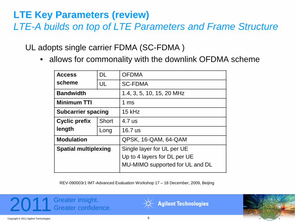
LTE Key Parameters (review)LTE-A builds on top of LTE Parameters and Frame Structure
UL adopts single carrier FDMA (SC-FDMA )• allows for commonality with the downlink OFDMA scheme
Access scheme
DL OFDMAUL SC-FDMA
Bandwidth 1.4, 3, 5, 10, 15, 20 MHzMinimum TTI 1 msSubcarrier spacing 15 kHzCyclic prefix length
Short 4.7 usLong 16.7 us
Modulation QPSK, 16-QAM, 64-QAMSpatial multiplexing Single layer for UL per UE
Up to 4 layers for DL per UEMU-MIMO supported for UL and DL
REV-090003r1 IMT-Advanced Evaluation Workshop 17 – 18 December, 2009, Beijing
5
Copyright © 2011 Agilent Technologies
2011 Greater insight.Greater confidence.
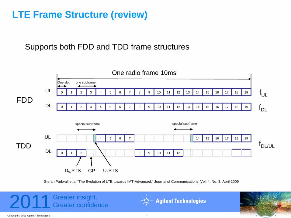
LTE Frame Structure (review)
Supports both FDD and TDD frame structures
Stefan Parkvall et al “The Evolution of LTE towards IMT-Advanced,” Journal of Communications, Vol. 4, No. 3, April 2009
0 1 2 3 4 5 6 7 8 9 10 11 12 13 14 15 16 17 18 19
0 1 2 3 4 5 6 7 8 9 10 11 12 13 14 15 16 17 18 19
One slot
One radio frame 10ms
FDD
4 5 6 7 14 15 16 17 18 19
0 1 2 8 9 10 11 12
UL
DL fDL
fUL
fDL/UL
special subframe
one subframe
DWPTS GP UpPTS
TDDUL
DL
special subframe
6

Copyright © 2011 Agilent Technologies
2011 Greater insight.Greater confidence.
20 MHzLTE terminal
LTE-Advanced terminal, 100MHz
(a) Contiguous carrier aggregation
… …(b) Non-contiguous carrier aggregation
20 MHzLTE terminal
LTE-Advanced terminal, 100MHz
LTE-A Enhancement #1: Carrier Aggregation• Wider bandwidth transmission using carrier
aggregation (CA) – support higher data rate– system bandwidths up to 100 MHz (5 component carriers
(CCs))
• Backward compatible with Rel-8 LTE when overlaid in IMT carrier bands.
• Supports both contiguous(figure a) and non-contiguous(figure b) carrier aggregation.
7

Copyright © 2011 Agilent Technologies
2011 Greater insight.Greater confidence.
Downlink Multiple Access Scheme with CA
Downlink OFDMA with component carrier (CC) based structure
• One transport block is mapped within one CC
• Parallel-type transmission for multi-CC transmission (in good alignment with Release 8 specifications)
• Cross-carrier scheduling is possible– DL control channels (such as PDCCH,
PCFICH, and PHICH) are updated to support cross-carrier scheduling.
– Add a Carrier Indicator Field (CIF) to DCI.
Channel coding
Channel coding
Channel coding
Channel coding
HARQ HARQ HARQ HARQ
Modulation Modulation Modulation Modulation
Mapping Mapping Mapping Mapping
Transportblock 1
Transport block 2
Transport block 3
Transport block 4
20MHz CC1
One eNB
20MHz CC2 20MHz CC3 20MHz CC4
8
Copyright © 2011 Agilent Technologies
2011 Greater insight.Greater confidence.
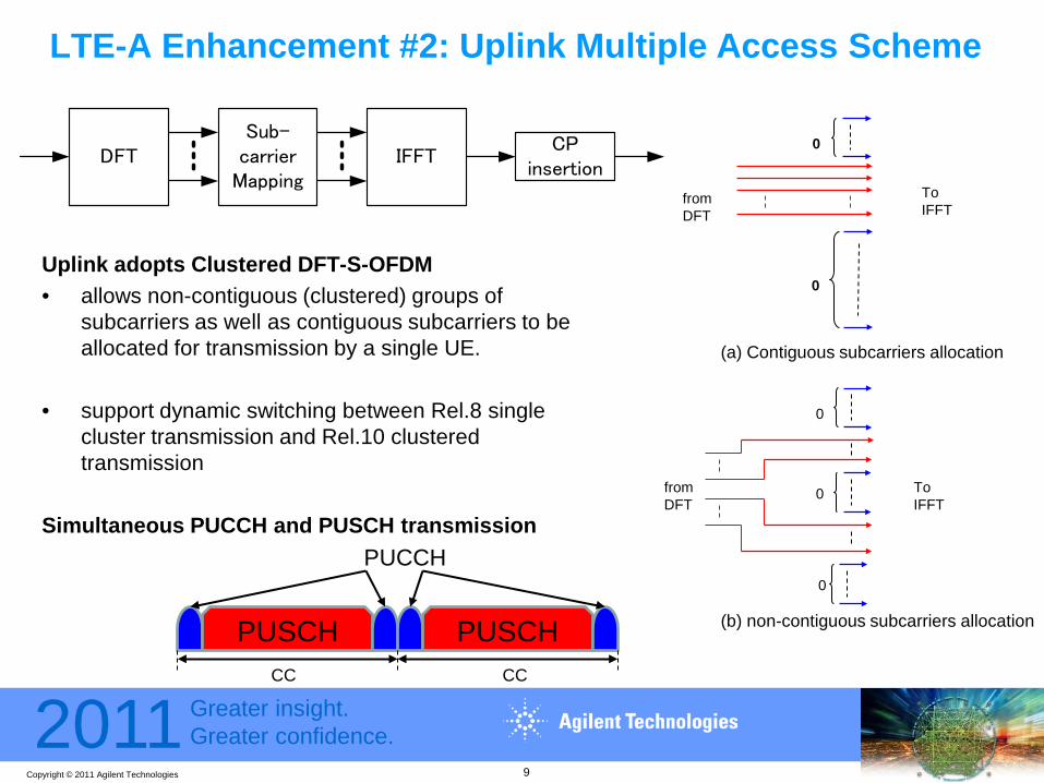
LTE-A Enhancement #2: Uplink Multiple Access Scheme
Uplink adopts Clustered DFT-S-OFDM• allows non-contiguous (clustered) groups of
subcarriers as well as contiguous subcarriers to be allocated for transmission by a single UE.
• support dynamic switching between Rel.8 single cluster transmission and Rel.10 clustered transmission
Simultaneous PUCCH and PUSCH transmission
DFTSub-
carrierMapping
IFFTCP
insertion
from DFT
ToIFFT
0
0
from DFT
ToIFFT
0
0
0
(a) Contiguous subcarriers allocation
(b) non-contiguous subcarriers allocation PUSCH PUSCH
PUCCH
CC CC
9
Copyright © 2011 Agilent Technologies
2011 Greater insight.Greater confidence.
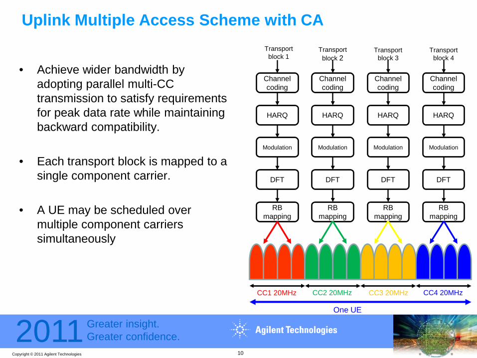
Uplink Multiple Access Scheme with CA
• Achieve wider bandwidth by adopting parallel multi-CC transmission to satisfy requirements for peak data rate while maintaining backward compatibility.
• Each transport block is mapped to a single component carrier.
• A UE may be scheduled over multiple component carriers simultaneously
Channel coding
Channel coding
Channel coding
HARQ HARQ HARQ
Modulation Modulation Modulation
RB mapping
RB mapping
RBmapping
Transportblock 1
Transport block 2
Transport block 3
CC1 20MHz
DFT DFT DFT
CC2 20MHz CC3 20MHz
Channel coding
HARQ
Modulation
RBmapping
Transport block 4
DFT
CC4 20MHz
One UE
10

Copyright © 2011 Agilent Technologies
2011 Greater insight.Greater confidence.
Uplink PUSCH Processing in LTE-Advanced
Figure (a) shows the same channel coding procedure as LTE.
Data arrives to the coding unit in the form of a maximum of two transport blocks every transmission time interval (TTI) per UL cell.
Figure (b) shows the uplink physical channel processing including MIMO processing.
Up to two codewords can be supported.
Transport block CRC attachment
Code block segmentationCode block CRC attachment
Channel coding
Rate matching
Code block attachment
Data and control multiplexing
Channel coding
CQI
Channel Interleaver
Channel coding
RI
Channel coding
ACK/NACK
(a) Transport channel processing for UL-SCH (b) Overview of uplink physical channel processing
Scrambling Modulation mapper
Layer
MapperPrecoding
Resource element mapper
OFDM signalgeneration
Scrambling Modulation mapper
Resource element mapper
OFDM signalgeneration
codewords layers antenna ports
Transform precoder
Transform precoder
11

Copyright © 2011 Agilent Technologies
2011 Greater insight.Greater confidence.
LTE-A Enhancement #3: multiple antenna transmission
• From 4 antennas/streams to 8 antennas/streams– Baseline being 4x4 with 4 UE Receive Antennas– Peak data rate reached with 8x8 SU-MIMO
• From 1 antenna/stream to 4 antennas/streams– Baseline being 2x2 with 2 UE Transmit Antennae– Peak data rate reached with 4x4 SU-MIMO
• Focus is initially on downlink beamsteering up to 4x2 antennas – SM is less attractive
• Challenges of higher order antenna transmission– Creates need for tower-mounted remote radio
heads– Increased power consumption– Increased product costs– Physical space for the antennae at both eNB and UE
UE
eNodeB
1, 2 or 4 transmitters and 2, 4 or 8 receivers
2, 4 or 8 transmitters and 2, 4 or 8 receivers
New for LTE-A
12
Copyright © 2011 Agilent Technologies
2011 Greater insight.Greater confidence.
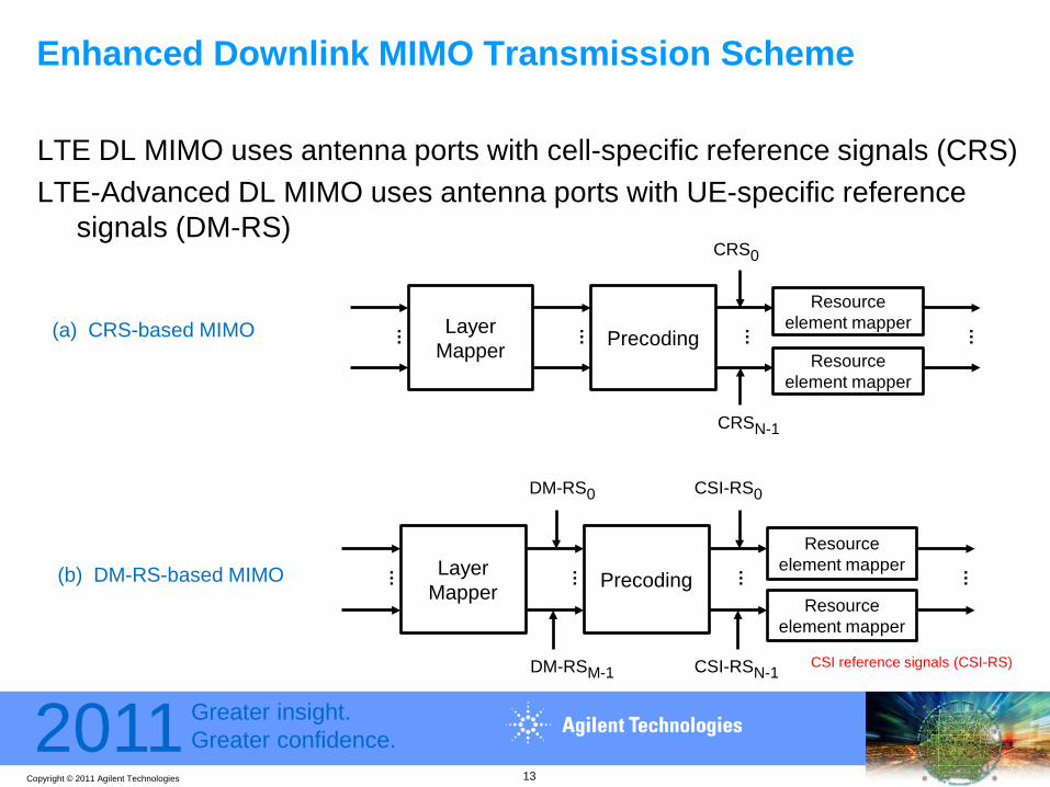
Enhanced Downlink MIMO Transmission Scheme
LTE DL MIMO uses antenna ports with cell-specific reference signals (CRS)LTE-Advanced DL MIMO uses antenna ports with UE-specific reference
signals (DM-RS)
Precoding
… …Layer Mapper
Resource element mapper
Resource element mapper
……
CRS0
CRSN-1
Precoding
… …Layer Mapper
Resource element mapper
Resource element mapper
……
DM-RS0
CSI-RSN-1
CSI-RS0
DM-RSM-1
(a) CRS-based MIMO
(b) DM-RS-based MIMO
CSI reference signals (CSI-RS)
13

Copyright © 2011 Agilent Technologies
2011 Greater insight.Greater confidence.
• Geometry-based stochastic model• Similar to WINNER II MIMO channel model• S x U, N Clusters (multipath)
LTE-Advanced MIMO Channel Model
Array 1(S Tx elements)
Array 2(U Rx elements)
14
Copyright © 2011 Agilent Technologies
2011 Greater insight.Greater confidence.
Array 1(S Tx
elements)
Array 2(U Rx
elements)
LTE-Advanced MIMO Channel Model
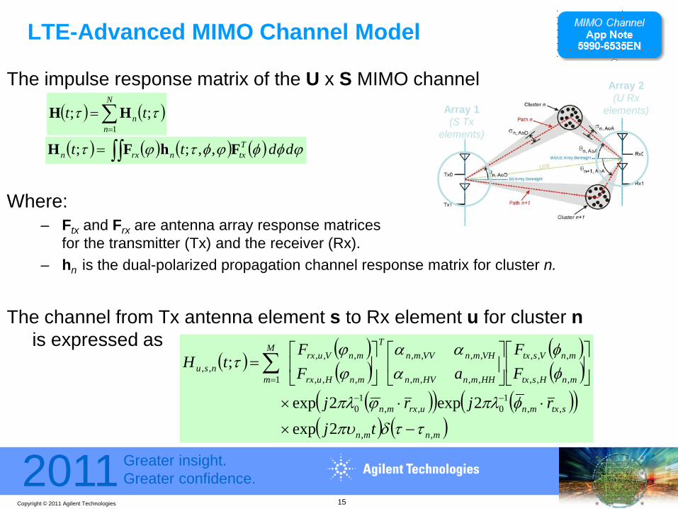
The impulse response matrix of the U x S MIMO channel
Where: – Ftx and Frx are antenna array response matrices
for the transmitter (Tx) and the receiver (Rx). – hn is the dual-polarized propagation channel response matrix for cluster n.
The channel from Tx antenna element s to Rx element u for cluster nis expressed as
( ) ( )∑=
=N
nn tt
1;; ττ HH
( ) ( ) ( ) ( )∫∫= ϕφφϕφτϕτ ddtt Ttxnrxn ,,;; FhFH
( ) ( )( )
( )( )
( )( ) ( )( )( ) ( )mnmn
stxmnurxmn
mnHstx
mnVstx
HHmnHVmn
VHmnVVmnT
mnHurx
mnVurxM
mnsu
tjrjrj
FF
aFF
tH
,,
,,1
0,,1
0
,,,
,,,
,,,,
,,,,
,,,
,,,
1,,
2exp 2exp2exp
;
ττδπυφπλϕπλ
φφ
ααα
ϕϕ
τ
−×
⋅⋅×
=
−−
=∑
15

Copyright © 2011 Agilent Technologies
2011 Greater insight.Greater confidence.
LTE-Advanced MIMO Channel Model (cont’d)
• Stage 1 of 3 consists of two steps. 1. First, the propagation scenario is selected. 2. Then, the network layout and the antenna configuration are determined.
• In Stage 2 of 3, large-scale and small-scale parameters are defined. ChIR
generationPropagation parameter
generationUser defined parameters
Scenario selection
-urban macro-urban micro
-indoor-out2in-etc.
Network Layout
-BS & MS locations-velocities
Antennas
-# elements-orientations
-field patterns
Large scale parameters
-DS, AS, K-XPR
-shadowing-path loss
Multi-path parameters
-power, delay, AoA, AoD, etc.
Channel coefficient generation
ChIR
0.5
1
1.5
2
30
210
60
240
90
270
120
300
150
330
180 0
Antenna 1 gain patternAntenna 2 gain pattern
Antenna pattern
16
Copyright © 2011 Agilent Technologies
2011 Greater insight.Greater confidence.
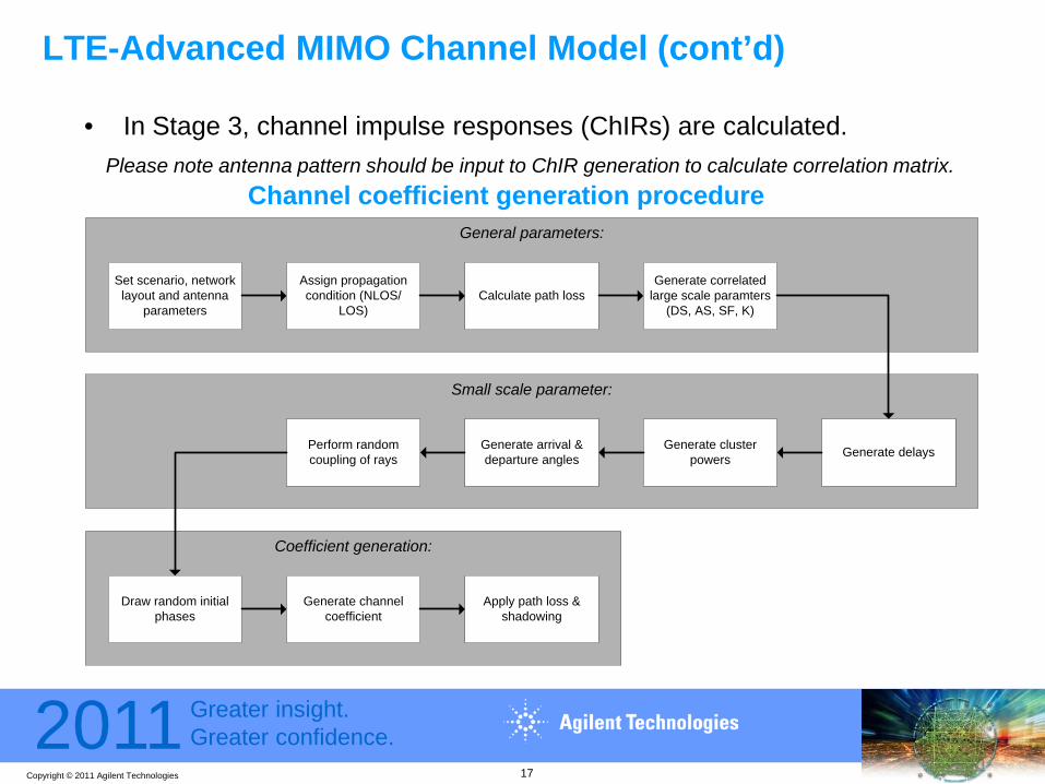
LTE-Advanced MIMO Channel Model (cont’d)
• In Stage 3, channel impulse responses (ChIRs) are calculated. Please note antenna pattern should be input to ChIR generation to calculate correlation matrix.
Coefficient generation:
Small scale parameter:
General parameters:
Set scenario, network layout and antenna
parameters
Assign propagation condition (NLOS/
LOS)Calculate path loss
Generate correlated large scale paramters
(DS, AS, SF, K)
Generate delaysGenerate cluster powers
Generate arrival & departure angles
Perform random coupling of rays
Draw random initial phases
Generate channel coefficient
Apply path loss & shadowing
Channel coefficient generation procedure
17

Copyright © 2011 Agilent Technologies
2011 Greater insight.Greater confidence.
Agenda
Standards Overview• LTE-Advanced - New Features• LTE-Advanced - Channel Model
Introduction to Agilent SystemVue
Design Challenges• Working algorithmic reference• Flexible early verification & project NRE• Carrier Aggregation & RF stress• MIMO & Channel considerations• Verification increasing
Conclusion and Q&A
18

Copyright © 2011 Agilent Technologies
2011 Greater insight.Greater confidence.
Unified architecture, verification tools for Layer 1 CommsAugments general purpose environments, or, stands on its own
PHY system integrationand verification
Cross-domain PHY modeling framework, for Model-Based Design
Complete a working PHY using combinations of Software, RF/BB Hardware, Simulation, and Measurements
Baseband AlgorithmsDataflow Simulation
RF Sys ArchitectureRF Simulators
Agilent SystemVue
PHY IP
TESTRF Hardware FlowsRFIC / MMIC
Hardware SiP / BoardHardware
Baseband Hardware Flows
GPP/ARMSoftware
DSP/ASSPSoftware
FPGA/ASIC/SoCHardware
19

Copyright © 2011 Agilent Technologies
2011 Greater insight.Greater confidence.
SystemVue Environment – A Comms PHY “Cockpit”
20
W1918 LTE-Advnaced170 parts14 reference designs26 examples/TBs

Copyright © 2011 Agilent Technologies
2011 Greater insight.Greater confidence.
.bitFiles
FPGASynthesis
Handwritten HDL
Custom IP
Integrated, top-down Comms ESL flow Cross-domain model-based design: RF, Comms, and C++/HDL
FPGA Target
REAL HARDWARE
HDL Simulator(s)
SIMULATED H/W
Dataflow Simulation
.m/C++ ALGORITHM
AlgorithmsC++, .m
MEASUREMENT, ANALYSIS
VSA softwareFlexDCA software
DIGITAL BITS, or MODULATED CARRIERS
MXG / ESG
Infiniium Scope
Logic Analyzer
MXA / PXA
Wideband arbs RF sensor
Target-neutralHDL Generation
System designRF Architecture
Baseband designPHY Reference
21
Copyright © 2011 Agilent Technologies
2011 Greater insight.Greater confidence.
Agenda
Standards Overview• LTE-Advanced - New Features• LTE-Advanced - Channel Model
Introduction to Agilent SystemVue
Design Challenges• Working algorithmic reference• Flexible early verification & project NRE• Carrier Aggregation & RF stress• MIMO & Channel considerations• Verification increasing
Conclusion and Q&A
22

Copyright © 2011 Agilent Technologies
2011 Greater insight.Greater confidence.
• As a design progresses :System Architecture Algorithm RTL finished hardware– How many different IP references get written, used, thrown away? (NRE)– Are they compatible? Flexible? Updated? – Are they from a trusted source?– Can you re-use tests and scripting?
• Are the BB and RF teams working from the same IP references?
• Everyone needs some level of algorithm reference.
• Now able to deliver this IP throughout the design flow
Design Challenge #1 – Working Algorithmic Reference
23

Copyright © 2011 Agilent Technologies
2011 Greater insight.Greater confidence.
SystemVue W1918 LTE-Advanced baseband libraryWhat is included?W1918 LTE-Advance BVL includes: Release 8
LTERelease 10
LTE-Advanced
Compiled dataflow simulation blocks 104 parts 66 parts
C++ “exploration” source code Optional, add-on not yet available
Packaged MIMO Sources/Receivers, w/GUI 10 ref designs 4 ref designs
Testbenches / Reference Examples 16 examples 10 (to date)
Works with existing instrument H/W Yes Yes
Works with Agilent 89600B VSA and SignalStudio software personalities
Yes Yes
Works with Agilent W1716 DPD Yes, integrated Yes, integrated
Works with Agilent W1715 MIMO Channelfor simulation-based fading
Yes Yes, extended for LTE-A
24

Copyright © 2011 Agilent Technologies
2011 Greater insight.Greater confidence.
W1918 LTE-Advanced baseband verification library An open, “Golden Reference” for model-based design
25
Code-generationWin32 DLL
C++ (special option*)
User IP.m math code
C++ RTL
Test Vectors & scripts
HDL test bench
FPGA Development Environment
FPGA Hardware Test SYSTEMVUE OUTPUT VECTOR
FPGA VECTOR
SYSTEMVUE OUTPUT VECTOR
HDL VECTORSYSTEMVUE INPUT VECTOR
SYSTEMVUE INPUT VECTOR
*LTE source code exploration library (W1912) is a special option
Algorithmic Development Environment
Copyright © 2011 Agilent Technologies
2011 Greater insight.Greater confidence.
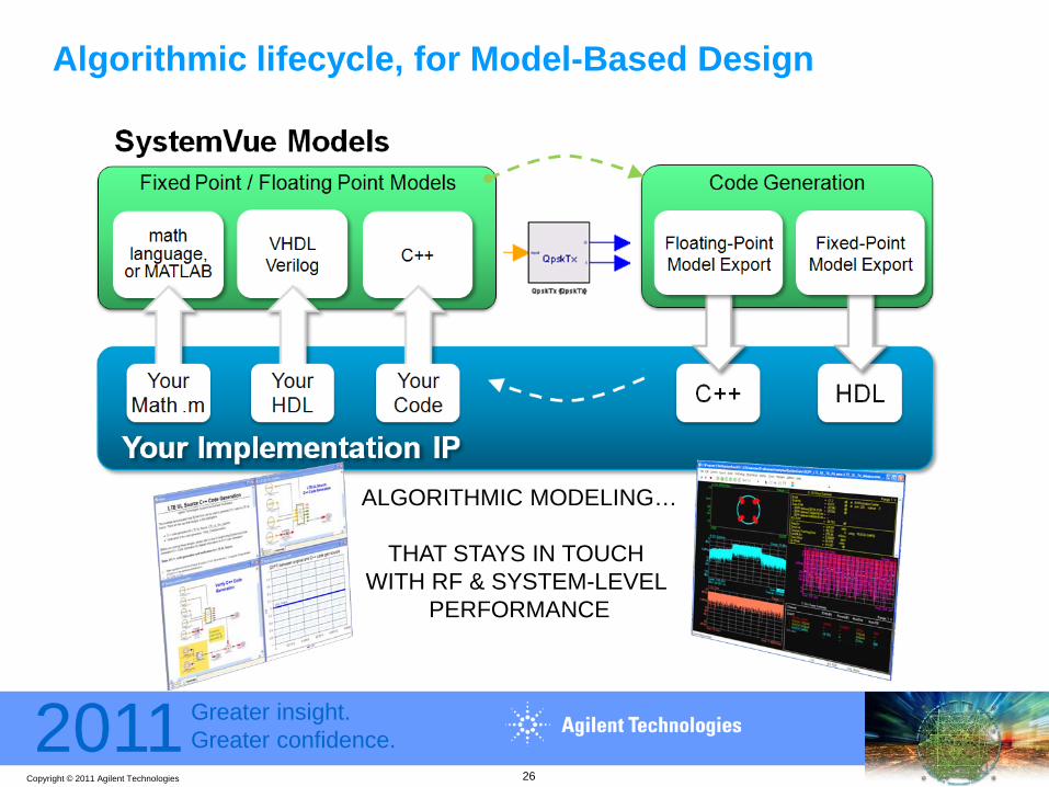
Algorithmic lifecycle, for Model-Based Design
26
ALGORITHMIC MODELING…
THAT STAYS IN TOUCH WITH RF & SYSTEM-LEVEL
PERFORMANCE

Copyright © 2011 Agilent Technologies
2011 Greater insight.Greater confidence.
SystemVue LTE-Advanced Library
Downlink Enhancement• Higher order DL MIMO: Up to 8 Tx 8 Rx Antennas• Support transmission to both R10 UEs and R8 UEs in a single source• Use DMRS to demodulate PDSCH• Precoding Codebook can be customized• Virtual Antenna Mapping: mapping matrix can be customized
Uplink Enhancement• Support Enhanced Uplink Multiple Access (clustered DFT-S-OFDM)• Support Uplink MIMO: up to 4 Tx and 4 Rx antennas
Carrier Aggregation• Support both inter and intra-band Carrier Aggregation
for both downlink and uplink
27
Copyright © 2011 Agilent Technologies
2011 Greater insight.Greater confidence.
• How do you verify a standard that keeps Evolving? (the E in LTE-A)
• Configuring standard-compliant test benches (such as TS 36.101-104) requires Scripting, Non-Recurring Engineering (NRE) project costs, and Reference IP
• Many tests also require a completed, operational system, with closed feedback loop (e.g. – for Throughput testing).
• SystemVue libraries typically provide
– 5-15 of pre-configured testbenches, per wireless standard– Complete working reference PHY to start with.– Parameterized, fully-coded, modifiable Sources, Receivers, etc– Specialized measurements for Throughput, EVM, ACLR, etc
Design Challenge #2 – Flexible early verification & NRE
28
Copyright © 2011 Agilent Technologies
2011 Greater insight.Greater confidence.
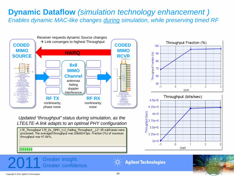
Dynamic Dataflow (simulation technology enhancement )Enables dynamic MAC-like changes during simulation, while preserving timed RF
Updated “throughput” status during simulation, as the LTE/LTE-A link adapts to an optimal PHY configuration
RF TXnonlinearity,phase noise
RF RXnonlinearity,
noise
8x8 MIMO
Channelantennas
fadingdoppler
interference
CODED MIMORCVR
CODED MIMO
SOURCE HARQ
Receiver requests dynamic Source changes Link converges to highest Throughput
29
Copyright © 2011 Agilent Technologies
2011 Greater insight.Greater confidence.
LTE-Advanced DL ThroughputThroughput measurements, up to 8x8, w/active HARQ
• Up to 8x8 MIMO• Fading, RF impairments• Fully coded/decoded• Closed loop, with
Active HARQ
30
ACK/NACK
LTE-AdvancedChannel Model
LTE-AdvancedDownlink
MIMO source
LTE-AdvancedDownlink
MIMO Receiver

Copyright © 2011 Agilent Technologies
2011 Greater insight.Greater confidence.
Hybrid Simulation/Test – Manually closing a loopLTE FDD UL Throughput Test (TS 36.141), or BER/BLER
Filter X
~
Filter A/D 1 2 3 4
DUGainDPDFilterX
~
A/D
RU DU
CPRI
Signal Generator
Signal Analyzer
SystemVue – Generates signal, then closes the loop
VSA 89600 waveform recordingSystemVue – LTE decode
Customer Hardware eNodeB receiver
STEP 1
STEP 2
31

Copyright © 2011 Agilent Technologies
2011 Greater insight.Greater confidence.
Leverage Simulation for R&D measurement applications that “fall between”
FILL HOLES
OFDM, MIMOLTE-Advanced
WNW, Defense
Jamming, InterfereClutter, TargetsRF, Phase NoiseCognitive environments
ThroughputCoded BER
DPD
MULTI-BOXCOORDINATION Digital vs. RF interfaces
Missing test coverageMissing user hardware
NON-STDWAVEFORMS
FADING,IMPAIRMENTS
32

Copyright © 2011 Agilent Technologies
2011 Greater insight.Greater confidence.
Pre-configured LTE-Advanced MIMO Sources & Receivers3 Levels of User Interaction are supported
Simplified, tabbed GUI Scriptable schematic
Open, parameterized, reference design
MIMO DL Source subnetwork
High level GUI Detailed piecesor
33
Copyright © 2011 Agilent Technologies
2011 Greater insight.Greater confidence.
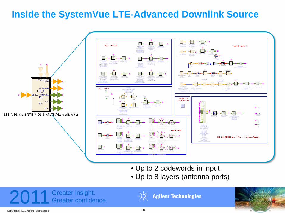
Inside the SystemVue LTE-Advanced Downlink Source
• Up to 2 codewords in input• Up to 8 layers (antenna ports)
34
Copyright © 2011 Agilent Technologies
2011 Greater insight.Greater confidence.
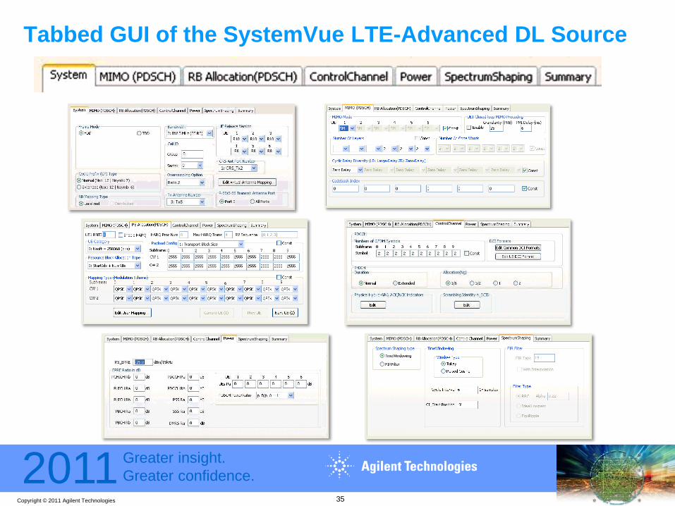
Tabbed GUI of the SystemVue LTE-Advanced DL Source
35
Copyright © 2011 Agilent Technologies
2011 Greater insight.Greater confidence.
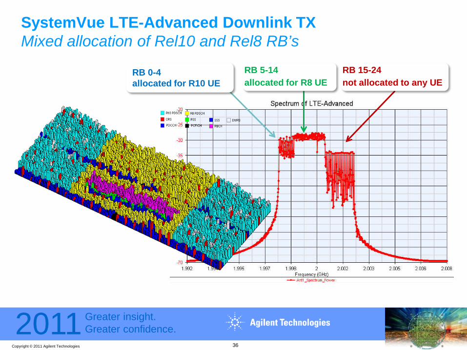
SystemVue LTE-Advanced Downlink TXMixed allocation of Rel10 and Rel8 RB’s
RB 0-4 allocated for R10 UE
RB 15-24 not allocated to any UE
RB 5-14 allocated for R8 UE
36
Copyright © 2011 Agilent Technologies
2011 Greater insight.Greater confidence.
Enhanced Uplink Multiple Access Design and test challenges
• Clustered SC-FDMA increases PAR by a few dB adding to transmitter linearity challenges
• Simultaneous PUCCH and PUSCH also increases PAR• Both feature create multi-carrier signals within the channel
bandwidth• High power narrow PUCCH plus single or clustered SC-FDMA
creates large opportunity for in-channel and adjacent channel spur generation– May require 3 to 4 dB power amp backoff for Rel-8 PA– Some scenarios may require 10 dB backoff.
37

Copyright © 2011 Agilent Technologies
2011 Greater insight.Greater confidence.
Inside the SystemVue LTE-Advanced Uplink Source
• Up to 2 codewords in input• Up to 4 layers (antenna ports)• Clustered DFT-S-OFDM
38
Copyright © 2011 Agilent Technologies
2011 Greater insight.Greater confidence.
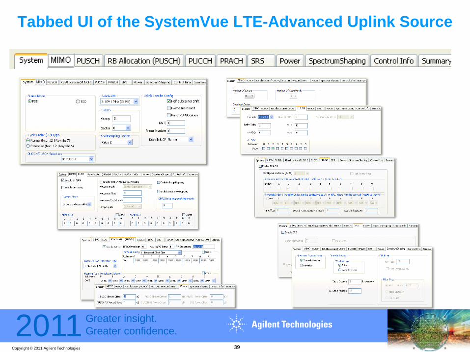
Tabbed UI of the SystemVue LTE-Advanced Uplink Source
39
Copyright © 2011 Agilent Technologies
2011 Greater insight.Greater confidence.
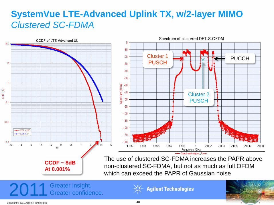
SystemVue LTE-Advanced Uplink TX, w/2-layer MIMOClustered SC-FDMA
Cluster 1 PUSCH
PUCCH
Cluster 2 PUSCH
CCDF ~ 8dBAt 0.001%
The use of clustered SC-FDMA increases the PAPR above non-clustered SC-FDMA, but not as much as full OFDM which can exceed the PAPR of Gaussian noise
40

Copyright © 2011 Agilent Technologies
2011 Greater insight.Greater confidence.
Enhanced Uplink Multiple Access Design and test challenges
Derived from R4-100427 ftp://ftp.3gpp.org/tsg_ran/WG4_Radio/TSGR4_54/Documents/R4-100427.zipThis is a typical spectrum of a single carrier signal
+30
+20
+10
0
-10
-20
-30
-40
-50
-60
-70
-80
-90
Mag
(dB
m)
-3 -2 -1 0 1 2 3
Spectrum RBW = 100 kHz
LO Feedthrough
UnwantedImage
Spurs Spurs
Wanted signal: 2 RBs wide @1 channel edge
41

Copyright © 2011 Agilent Technologies
2011 Greater insight.Greater confidence.
Enhanced Uplink Multiple Access Design and test challenges
Derived from R4-100427 ftp://ftp.3gpp.org/tsg_ran/WG4_Radio/TSGR4_54/Documents/R4-100427.zipThe presence of two in-channel carriers creates 25 to 50 dB worse spurs
+30
+20
+10
0
-10
-20
-30
-40
-50
-60
-70
-80
-90
Mag
(dB
m)
-3 -2 -1 0 1 2 3
Spectrum RBW = 100 kHz
Spurs Spurs
Wanted signal: 1 RB @
2 channel edges
42

Copyright © 2011 Agilent Technologies
2011 Greater insight.Greater confidence.
• Increased bandwidth of Carrier Aggregation drives PAPR to extreme levels
• Crest-Factor Reduction strategies are essential to offset this increase
• Increased RF bandwidth also exposes frequency-dependence and other analog degradations, which crosses multiple CC’s
• Combinations of several factors: Non-contiguous Carrier Aggregation, the multitude of possible RF Bands, and number of MIMO layers make these RF designs a true challenge.
• How do you translate real RF limitations back up to system-level performance? Can you correlate PHY simulations with measurements?
Design Challenge #3 – Carrier Aggregation stressing RF
43

Copyright © 2011 Agilent Technologies
2011 Greater insight.Greater confidence.
Using SystemVue to make LTE-Advanced CA signalsScenario number
Deployment scenarioTransmission BWs of LTE-A carriers
# of LTE-A component carriersBands for LTE-A
carriersDuplex modes
1Single-band contiguous spec. alloc. @ 3.5GHz band for FDD
UL: 40 MHz
DL: 80 MHz
UL: Contiguous 2x20 MHz CCsDL: Contiguous 4x20 MHz CCs
3.5 GHz band FDD
2Single-band contiguous spec. alloc. @ Band 40 for TDD
100 MHz Contiguous 5x20 MHz CCsBand 40 (2.3 GHz)
TDD
4Single-band, non-contiguous spec. alloc. @ 3.5GHz band for FDD
UL: 40 MHz
DL: 80 MHz
UL: Non-contiguous 1x20 + 1x20 MHz CCsDL: Non-contiguous 2x20 + 2x20 MHz CCs
3.5 GHz band FDD
20 MHz CCs
44
80 MHz total
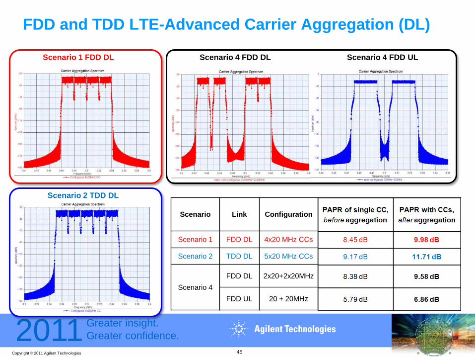
Copyright © 2011 Agilent Technologies
2011 Greater insight.Greater confidence.
FDD and TDD LTE-Advanced Carrier Aggregation (DL)
Scenario Link Configuration PAPR of single CC,before aggregation
PAPR with CCs, after aggregation
Scenario 1 FDD DL 4x20 MHz CCs 8.45 dB 9.98 dB
Scenario 2 TDD DL 5x20 MHz CCs 9.17 dB 11.71 dB
Scenario 4 FDD DL 2x20+2x20MHz 8.38 dB 9.58 dB
FDD UL 20 + 20MHz 5.79 dB 6.86 dB
Scenario 1 FDD DL
Scenario 2 TDD DL
Scenario 4 FDD DL Scenario 4 FDD UL
45

Copyright © 2011 Agilent Technologies
2011 Greater insight.Greater confidence.
Validating early Standards proposals (such as CA)
46
Early Algorithm validationEarly RF architecture validationTrusted 3rd party IP reference
Software-definedinstruments help with emerging standards
support
Leverage a system/algorithm tool for early architecture “reality check”“How far away is my existing design?” “Can I fix it cheaply in software?”

Copyright © 2011 Agilent Technologies
2011 Greater insight.Greater confidence.
• Models/corrects for PA nonlinearities and memory effects
• Works with test equipment,and RF circuit co-simulation
• Achieves 15-20dB for 20MHz LTE; now being evaluated for LTE-A
• Quickly assesses the “correctability” of a PA
• Can model the “dirty” PAfor inclusion in Layer 1 link-level architecture studies
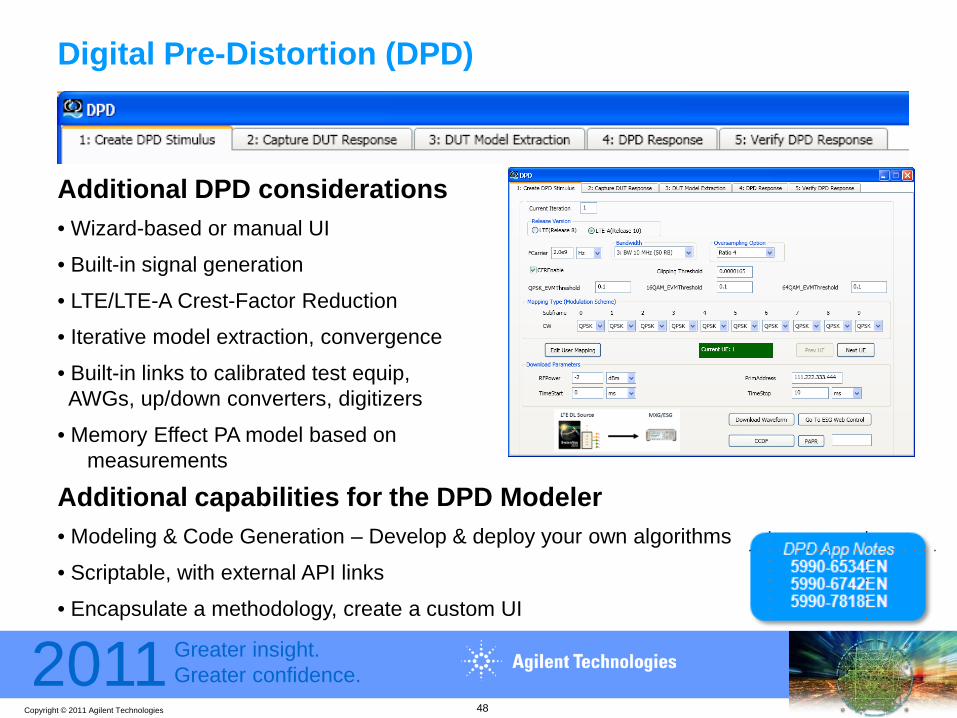
Digital Pre-Distortion (DPD)
47
6C-GSM
LTE
LTE-A
Memory Effects
Copyright © 2011 Agilent Technologies
2011 Greater insight.Greater confidence.
Digital Pre-Distortion (DPD)
Additional DPD considerations• Wizard-based or manual UI
• Built-in signal generation
• LTE/LTE-A Crest-Factor Reduction
• Iterative model extraction, convergence
• Built-in links to calibrated test equip, AWGs, up/down converters, digitizers
• Memory Effect PA model based on measurements
Additional capabilities for the DPD Modeler• Modeling & Code Generation – Develop & deploy your own algorithms
• Scriptable, with external API links
• Encapsulate a methodology, create a custom UI
48

Copyright © 2011 Agilent Technologies
2011 Greater insight.Greater confidence.
DPD of LTE-Advanced, using M9330A/M9392A 2x20MHz + 2x20MHz non-contiguous CCs, (100MHz signal BW)
49
For BW 140-250 MHz, Agilent M9392A is available
- 12bits ADC- up to 250MHz bandwidth- over 2.5GHz - may require wideband AWG
For BW < 140 MHz: Agilent PXA is recommended
- 14bits ADC- can reach down to -100dBm- greater DPD improvements
Sampling rate=245.76MHz

Copyright © 2011 Agilent Technologies
2011 Greater insight.Greater confidence.
Simulation vs. Measurement DPD Extraction Approaches
50
External Trigger
Attenuator N5182 MXG
or E8257D PSGas external modulatorM9330A AWG if > 100 MHz
89600VSA
M9392A PXI VSA (>140MHz)or N9030A PXA (<140 MHz)
I,Q RF
RF DUT
SIMULATION-BASED DPD(predictive)
• ADS & GoldenGate Circuits as simulated RF DUTs- Complex loading, memory FX, dynamic behaviors
• NVNA X-parameter measurement model,- Great for smaller solid-state devices
X-parameters
RF DUTN5241,2 PNA-X
MEASUREMENT-BASED DPD
CO-SIM, MODELS
CO-SIM, MODELS
MODEL
ADS
GG

Copyright © 2011 Agilent Technologies
2011 Greater insight.Greater confidence.
• MIMO “multiplicity” is adding to the verification effort; Do 8x4 and 8x8 provide the performance for an ROI?
• Virtual techniques (Agilent MIMO OTA approach, and simulation links from bottom-up EDA flows) can bridge gaps
• A surprising level of accuracy is attainable at the algorithm/architecture stage of a design
• Comparable algorithms can be used in both simulation and at-speed hardware faders; this symmetry can ease the transition to verification
Design Challenge #4 – MIMO and Channel considerations
51

Copyright © 2011 Agilent Technologies
2011 Greater insight.Greater confidence.
W1715 MIMO Channel Model (for LTE-Advanced)Predictive, simulation-based fading, for up to 8x8 MIMO
WINNER II Channel Emulator Module
Scenario Selection/Network Layout/
Antennas
Input Ports
Output Ports
Large Scale & Small Scale Parameters Generation
Fading Coefficient Generation
Fading EngineTransmitting Signals
Faded Signals
User Define Parameters
52

Copyright © 2011 Agilent Technologies
2011 Greater insight.Greater confidence.
LTE-Advanced Channel Modelling in SystemVuePredictive, simulation-based fading, from 3DEM analyses
from Agilent EMPro simulations
from Anechoic measurements
PHYSICAL ANTENNA PATTERNS
antenna pattern file 1
antenna pattern file 2
antenna pattern file N
FILES
. . .
W1715 MIMO CHANNEL MODEL
53

Copyright © 2011 Agilent Technologies
2011 Greater insight.Greater confidence.
LTE-Advanced Channel Modelling in SystemVue
Antenna Patterns, loaded by human Throughput % vs. array rotation angle(with/without human)
54

Copyright © 2011 Agilent Technologies
2011 Greater insight.Greater confidence.
SystemVue 2x2 MIMO Downlink ThroughputExperimental & Simulated results vs. Angle-of-Arrival
0 50 100 150 200 250 300 3500.84
0.86
0.88
0.9
0.92
0.94
0.96
0.98
1
1.02
AoA in degree
Thro
ughp
ut F
acto
r
Experiment ResultsSimulation Results
2x2 LTE-A Throughput %
Transition from Simulations to Test
DUT
55
It is possible to get early, realistic system-level results for MIMO
Incorporate preliminary designs for - Baseband PHY, and user IP- Industrial design & Antenna placement- RF transceivers (pre-tapeout)- Interference, and signaling environment
Challenge: Simulation speed, and amount of actual coverage testing
Copyright © 2011 Agilent Technologies
2011 Greater insight.Greater confidence.
Verification dimensionality expanding vs.– BB PHY operating modes of LTE-Advanced, LTE, 3G, WLAN, MIMO– RF Spectral allocations/bands, and analog control settings– Semiconductor processes, battery, and environmental conditions
Scripting, regressions, IP exchange, and testbenches across domains
– RF models have been simplistic in Baseband in order to be fast
– Baseband Algorithms are dumbed down to static modes for CW RF– no frequency response, no memory effects, noise, or dynamic phenomena
The next generation of tools are addressing these challenges
Design Challenge #5 – Verification increasing dramatically
56
Copyright © 2011 Agilent Technologies
2011 Greater insight.Greater confidence.
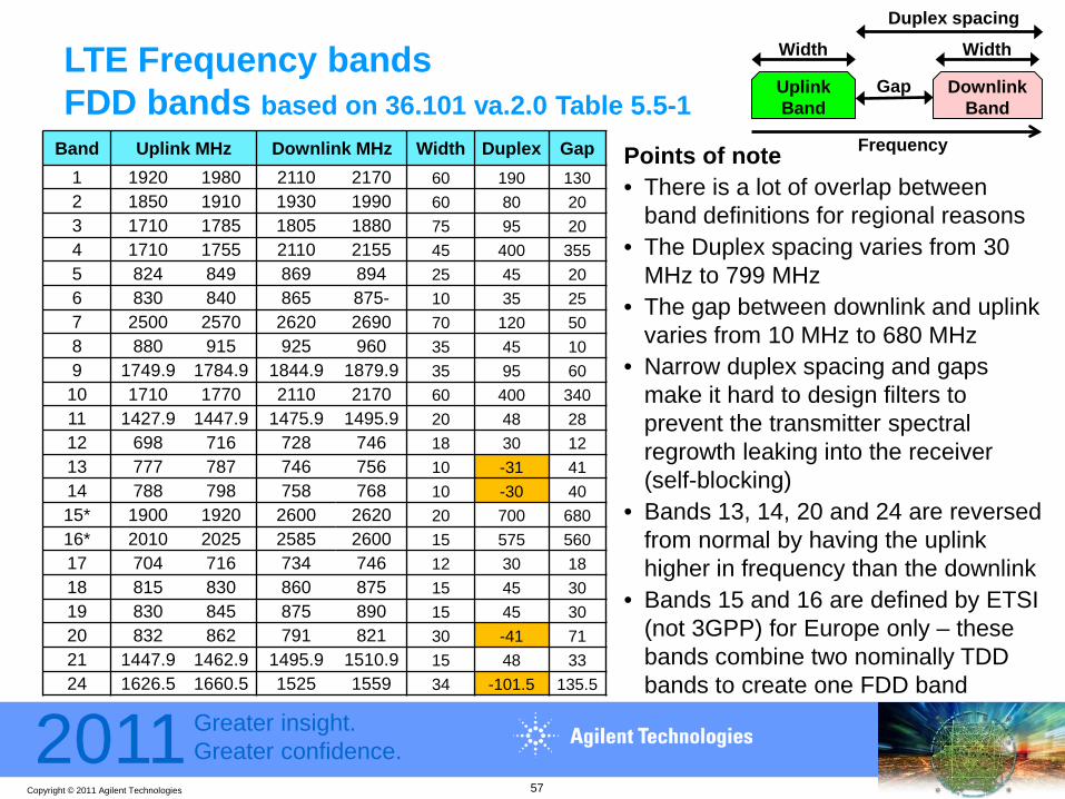
Band Uplink MHz Downlink MHz Width Duplex Gap1 1920 1980 2110 2170 60 190 1302 1850 1910 1930 1990 60 80 203 1710 1785 1805 1880 75 95 204 1710 1755 2110 2155 45 400 3555 824 849 869 894 25 45 206 830 840 865 875- 10 35 257 2500 2570 2620 2690 70 120 508 880 915 925 960 35 45 109 1749.9 1784.9 1844.9 1879.9 35 95 60
10 1710 1770 2110 2170 60 400 34011 1427.9 1447.9 1475.9 1495.9 20 48 2812 698 716 728 746 18 30 1213 777 787 746 756 10 -31 4114 788 798 758 768 10 -30 4015* 1900 1920 2600 2620 20 700 68016* 2010 2025 2585 2600 15 575 56017 704 716 734 746 12 30 1818 815 830 860 875 15 45 3019 830 845 875 890 15 45 3020 832 862 791 821 30 -41 7121 1447.9 1462.9 1495.9 1510.9 15 48 3324 1626.5 1660.5 1525 1559 34 -101.5 135.5
Points of note• There is a lot of overlap between
band definitions for regional reasons• The Duplex spacing varies from 30
MHz to 799 MHz• The gap between downlink and uplink
varies from 10 MHz to 680 MHz• Narrow duplex spacing and gaps
make it hard to design filters to prevent the transmitter spectral regrowth leaking into the receiver (self-blocking)
• Bands 13, 14, 20 and 24 are reversed from normal by having the uplink higher in frequency than the downlink
• Bands 15 and 16 are defined by ETSI (not 3GPP) for Europe only – these bands combine two nominally TDD bands to create one FDD band
LTE Frequency bandsFDD bands based on 36.101 va.2.0 Table 5.5-1
UplinkBand
DownlinkBand
Gap
Duplex spacing
Width Width
Frequency
57

Copyright © 2011 Agilent Technologies
2011 Greater insight.Greater confidence.
Points of note• For TDD there is no concept of duplex
spacing or gap since the downlink and uplink frequencies are the same
• As such, the challenge of separating transmit from receive does not require a duplex filter for the frequency domain but a switch for the time domain
LTE Frequency bandsTDD bands based on 36.101 va.2.0 Table 5.5-1
Band Uplink MHz Downlink MHz Width
33 1900 1920 1900 1920 20
34 2010 2025 2010 2025 15
35 1850 1910 1850 1910 60
36 1930 1990 1930 1990 60
37 1910 1930 1910 1930 20
38 2570 2620 2570 2620 50
39 1880 1920 1880 1920 40
40 2300 2400 2300 2400 100
41 2496 2690 2496 2690 194
42 3400 3600 3400 3600 200
43 3600 3800 3600 3800 200
TransceiveBand
Width
Frequency
58
Copyright © 2011 Agilent Technologies
2011 Greater insight.Greater confidence.
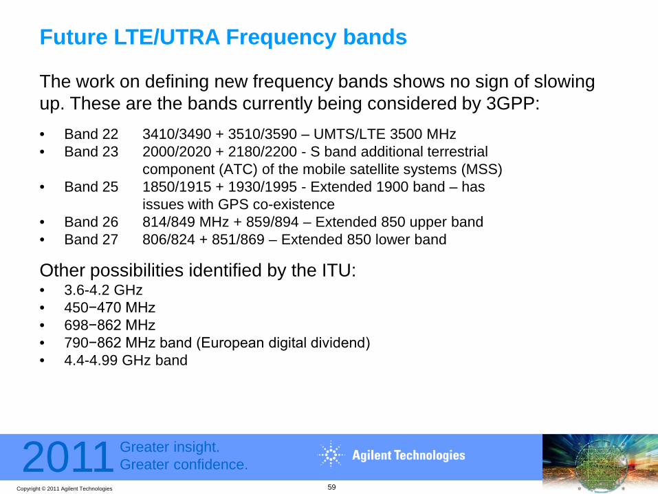
Future LTE/UTRA Frequency bands
The work on defining new frequency bands shows no sign of slowing up. These are the bands currently being considered by 3GPP:• Band 22 3410/3490 + 3510/3590 – UMTS/LTE 3500 MHz• Band 23 2000/2020 + 2180/2200 - S band additional terrestrial
component (ATC) of the mobile satellite systems (MSS)• Band 25 1850/1915 + 1930/1995 - Extended 1900 band – has
issues with GPS co-existence• Band 26 814/849 MHz + 859/894 – Extended 850 upper band• Band 27 806/824 + 851/869 – Extended 850 lower band
Other possibilities identified by the ITU:• 3.6-4.2 GHz• 450−470 MHz• 698−862 MHz• 790−862 MHz band (European digital dividend)• 4.4-4.99 GHz band
59
Copyright © 2011 Agilent Technologies
2011 Greater insight.Greater confidence.
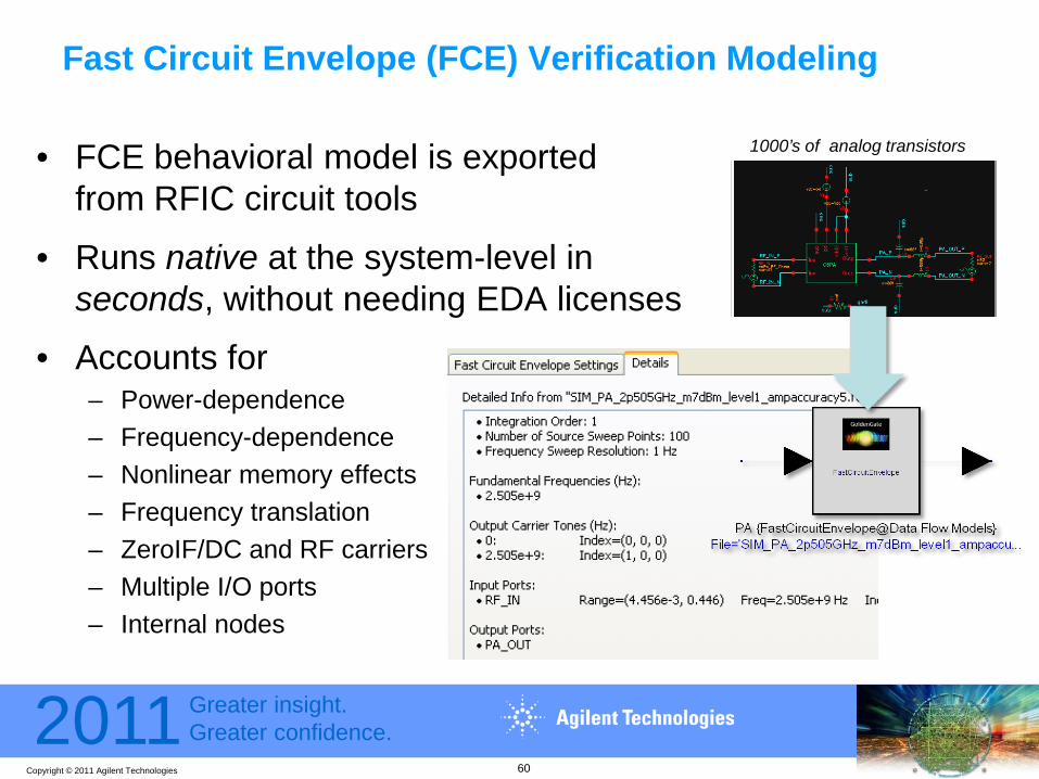
Fast Circuit Envelope (FCE) Verification Modeling
• FCE behavioral model is exported from RFIC circuit tools
• Runs native at the system-level in seconds, without needing EDA licenses
• Accounts for– Power-dependence– Frequency-dependence– Nonlinear memory effects– Frequency translation– ZeroIF/DC and RF carriers– Multiple I/O ports– Internal nodes
60
1000’s of analog transistors

Copyright © 2011 Agilent Technologies
2011 Greater insight.Greater confidence.
Fast Circuit Envelope (FCE) Verification ModelingExample: FCE model used in an LTE Uplink test
Coded LTE UL5 MHz sourceSystemVue W1910/W1918 library
RFIC CMOS PA “FastCircuitEnvelope” model
Exported from GoldenGate
89600 VSA LTE demod
TUNE MODE
61
SCRIPTABLE ENVIRONMENTSCRIPTABLE PARAMETERS
Copyright © 2011 Agilent Technologies
2011 Greater insight.Greater confidence.
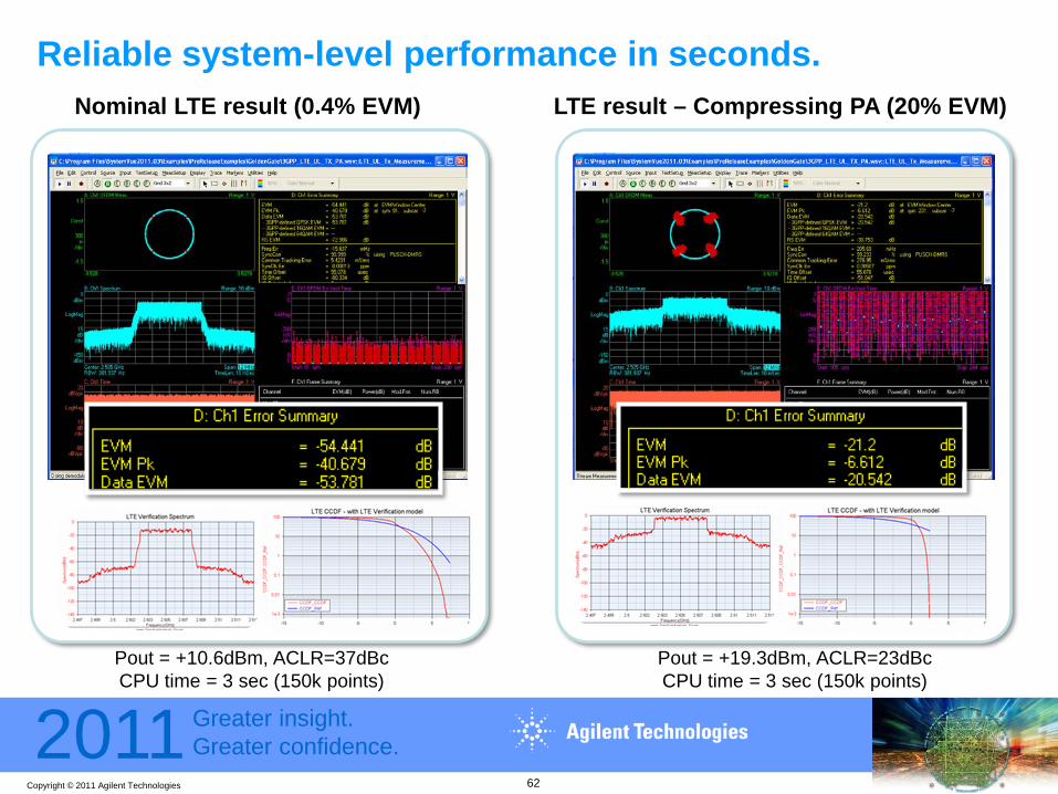
Reliable system-level performance in seconds.
Pout = +19.3dBm, ACLR=23dBcCPU time = 3 sec (150k points)
Pout = +10.6dBm, ACLR=37dBcCPU time = 3 sec (150k points)
Nominal LTE result (0.4% EVM) LTE result – Compressing PA (20% EVM)
62

Copyright © 2011 Agilent Technologies
2011 Greater insight.Greater confidence.
Deepest Insights: Direct circuit envelope co-simulation
I,Q
CLOSED-LOOP LTE UL
Throughput
RFIC environmt(remote Linux)
Upconvert/TX RFIC
RFIC environmt(remote Linux)
LowNoise Amp RFIC
RF RF RF
• Dynamic RF behavior• Standards-compliant• High accuracy• Directly uses the
design databases (not an indirect model)
63

Copyright © 2011 Agilent Technologies
2011 Greater insight.Greater confidence.
Other approaches: Native RF System modeling Bringing RF System Architectures up to the PHY-level
Drag & DropDataflow modeling “on the fly”
From X-parameters
• Dedicated simulator for RF system architecture• Local RF analog effects (e.g. - X-parameters)• Drag &drop the whole RF chain into Dataflow• Able to do MIMO and ZeroIF architectures
To PHY system performanceTo RF System
Architectures
To PHY-level Systems

Copyright © 2011 Agilent Technologies
2011 Greater insight.Greater confidence.
Agenda
Standards Overview• LTE-Advanced - New Features• LTE-Advanced - Channel Model
Introduction to Agilent SystemVue
Design Challenges• Working algorithmic reference• Flexible early verification & project NRE• Carrier Aggregation & RF stress• MIMO & Channel considerations• Verification increasing
Conclusion and Q&A
65
Copyright © 2011 Agilent Technologies
2011 Greater insight.Greater confidence.
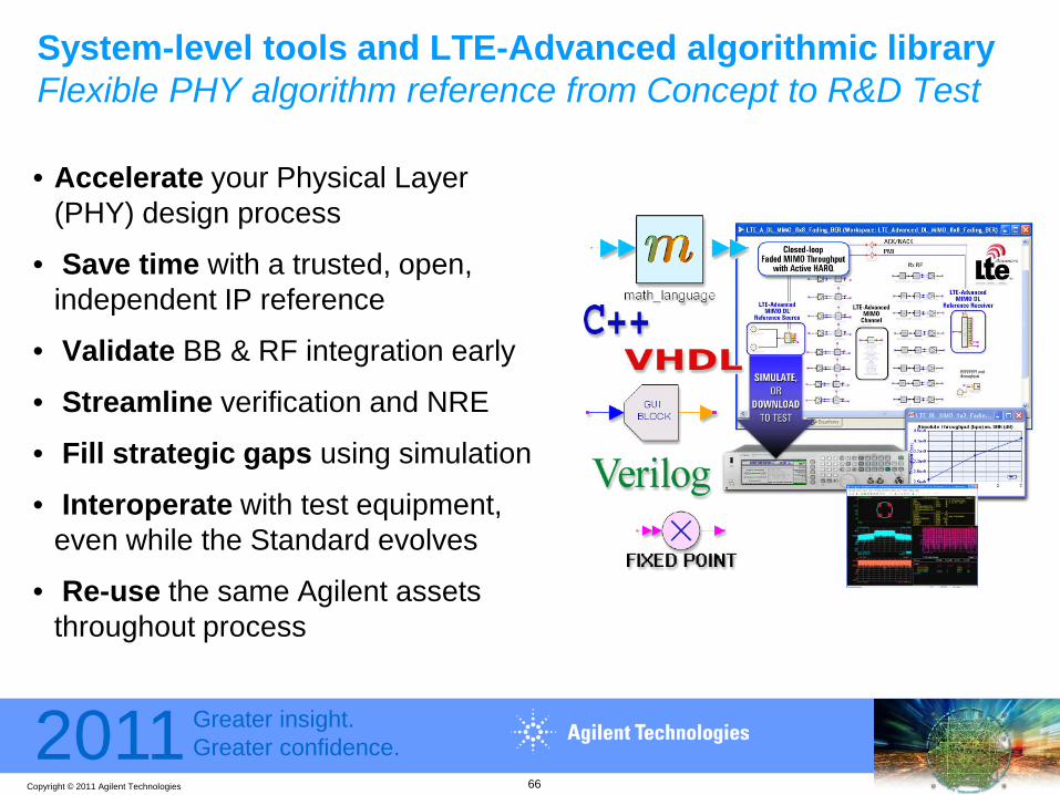
System-level tools and LTE-Advanced algorithmic libraryFlexible PHY algorithm reference from Concept to R&D Test
• Accelerate your Physical Layer (PHY) design process
• Save time with a trusted, open, independent IP reference
• Validate BB & RF integration early
• Streamline verification and NRE
• Fill strategic gaps using simulation
• Interoperate with test equipment, even while the Standard evolves
• Re-use the same Agilent assets throughout process
66
Copyright © 2011 Agilent Technologies
2011 Greater insight.Greater confidence.
LTE-Advanced PHY presents significant new BB and RF design challenges
The EDA tools are also providing significant new capabilities to address these challenges. What was shown today is already available.
Seen today:– “instrument grade” Standards IP reference, usable throughout the design process– Modular top-down ESL design approach across both Baseband and RF domains– High-performance measurement and modeling techniques – Open SW/HW platform, with single-vendor worldwide apps & support
Visit us at regional Agilent seminar tours and industry trade shows, or on the web at http://www.agilent.com/find/eesof-systemvue-lte-advanced
Conclusion
67
Copyright © 2011 Agilent Technologies
2011 Greater insight.Greater confidence.
Questions?
68
Copyright © 2011 Agilent Technologies
2011 Greater insight.Greater confidence.
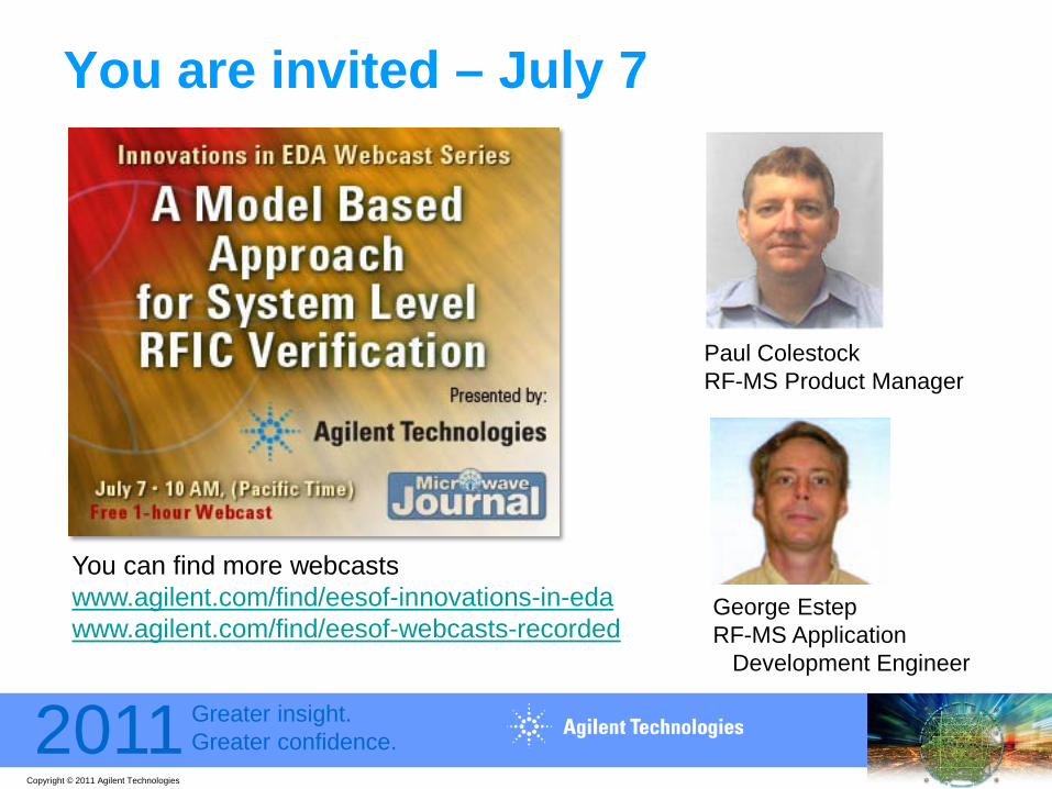
You are invited – July 7
You can find more webcastswww.agilent.com/find/eesof-innovations-in-edawww.agilent.com/find/eesof-webcasts-recorded
Paul ColestockRF-MS Product Manager
George EstepRF-MS Application
Development Engineer

Copyright © 2011 Agilent Technologies
2011 Greater insight.Greater confidence.
App Notes and Videos Referenced in this presentationSlide Agilent Literature
numberTitle/Description
4 5990-6706EN Introduction to LTE-Advanced14 Webcast
EEtimes“Theories, Techniques, and Validation of Over-The-Air (OTA) Test Methods for Evaluating the Performance of MIMO Handsets” (September, 2010)
15,55 5990-6535EN MIMO Channel modeling with SystemVue24 5990-8135EN SystemVue LTE-Advanced Library25 5990-3357EN LTE Reference Vector (whitepaper on model-based design methodology)25 YouTube video “Model Configurations for Easy Control of Model Polymorphism”
http://www.youtube.com/watch?v=LEEibGvIDvc
27 5990-7146EN Using SystemVue LTE-Advanced Signal Generation and Measurement31 5990-6202EN SystemVue for LTE Throughput46 5990-7757EN SystemVue for “Design-Validate-Test” (tutorial)48 5990-6534EN Using SystemVue for Digital Pre-Distortion48 Webcast
5990-6742EN“4G For Everyone: Extended RF Performance with Digital Pre-Distortion”
48 5990-7818EN “Making Digital Pre-Distortion Fast and Practical for all Engineers”61 YouTube video “Fast Circuit Envelope Models for RFIC verification”
http://www.youtube.com/watch?v=7k8TS2Due70
61 July 2011 webcast “A Model-based approach to System-Level RFIC Verification”http://www.agilent.com/find/innovations-in-EDA
70
For Agilent literature on the web, replace the digits in http://cp.literature.agilent.com/litweb/pdf/xxxx-xxxxxx.pdf with the literature number