lt36147 diesel pro fh235_fh236_fh241 installation ... diesel... · installation instructions diesel...
TRANSCRIPT

� CAUTION: These instructions are intended for use by professional mechanics who are trained in the proper use of power and hand tools, using appropriate safety precautions (including eye protection).
Diesel Pro® FH235, FH236 and FH241Series Filter/Separator/Warmer
Installation InstructionsParts ListDiesel Pro® 235
Part Description Part Number
AFH235 Cover Assembly (includes Vent Cap, Vent Cap O-Ring, Collar, Cover, Cover O-Ring, and Spring)
3973506 S
BBiodiesel O-Ring Pack – only required for >B5 fuel (includes Vent Cap O-Ring and Cover O-Ring)
3950444 S
C Filter Element See page 9
D Check Valve Assembly 3972249 S
E Diesel Pro® FH235, Unheated See page 12
FAdapter - 7/8"-14 to M16 x 1.5Adapter - 7/8"-14 to 3/8" NPT
3973689 S3980209 S
G
Pre-Heater, 12 V, 195 W, WP ConnectorPre-Heater, 24 V, 195 W, WP ConnectorPre-Heater, 24 V, 195 W, Tyco Connector120 VAC, 75 W Heater
SP1312 SP1313SP1314
3980208 S
HBottom Bowl Assembly (includes Bottom Bowl Seal, Bottom Bowl, Screws, Drain Valve O-Ring, and Drain Valve)
3972255 S
I Water-In-Fuel (WIF) Sensor 3957158 S
JCollar for Reduced Clearance Applications (optional) 3945059 S
K Collar Wrench, Metal 3944458 S
NotShown
WIF Wiring Harness 3950729 SWIF LED 3946670 S
L Manual Primer Pump Plunger Assembly 3975110 S
M Manual Primer Pump Check Valve 3975109 S
NManual Primer Pump (M16) 3979203 SManual Primer Pump (M18) 3979202 S
O Primer Pump Service Kit 3975111 S
PCheck Valve (M16) 3981659 SCheck Valve (M18) 3981660 S
B
C
E
D
F
F
G
I
AFH235 Cover
AssemblyIncludes
Vent Cap,Vent Cap O-Ring,
Collar, Cover,Cover O-Ring,
and Spring
Biodiesel O-Ring PackIncludes Vent Cap O-Ringand Cover O-Ring
K
J
HBottom Bowl AssemblyIncludes Bottom Bowl Seal,Bottom Bowl, Screws, Drain Valve O-Ring, and Drain Valve
Manual Primer Pumps
LO
L
P
MN
3981659 S (M16)3981660 S (M18)
3979203 S (M16)3979202 S (M18)
page 2
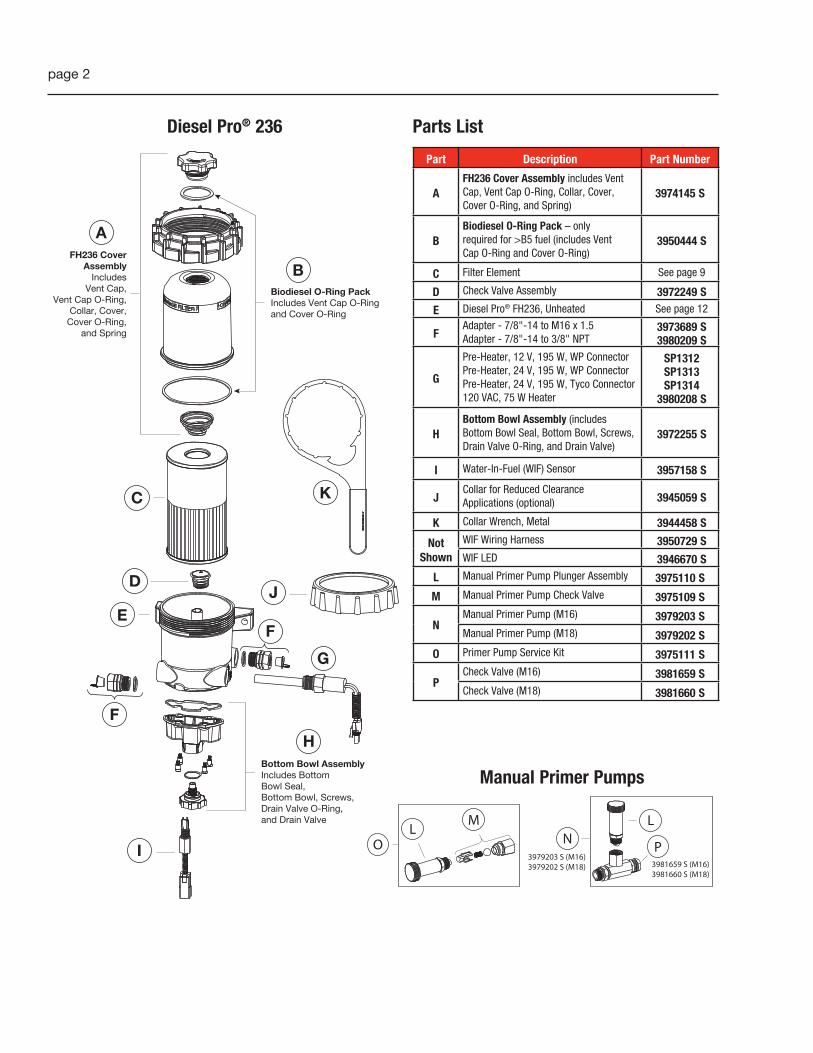
Parts ListDiesel Pro® 236
Part Description Part Number
AFH236 Cover Assembly includes Vent Cap, Vent Cap O-Ring, Collar, Cover, Cover O-Ring, and Spring)
3974145 S
BBiodiesel O-Ring Pack – only required for >B5 fuel (includes Vent Cap O-Ring and Cover O-Ring)
3950444 S
C Filter Element See page 9
D Check Valve Assembly 3972249 S
E Diesel Pro® FH236, Unheated See page 12
FAdapter - 7/8"-14 to M16 x 1.5Adapter - 7/8"-14 to 3/8" NPT
3973689 S3980209 S
G
Pre-Heater, 12 V, 195 W, WP ConnectorPre-Heater, 24 V, 195 W, WP ConnectorPre-Heater, 24 V, 195 W, Tyco Connector120 VAC, 75 W Heater
SP1312 SP1313SP1314
3980208 S
HBottom Bowl Assembly (includes Bottom Bowl Seal, Bottom Bowl, Screws, Drain Valve O-Ring, and Drain Valve)
3972255 S
I Water-In-Fuel (WIF) Sensor 3957158 S
JCollar for Reduced Clearance Applications (optional) 3945059 S
K Collar Wrench, Metal 3944458 S
NotShown
WIF Wiring Harness 3950729 SWIF LED 3946670 S
L Manual Primer Pump Plunger Assembly 3975110 S
M Manual Primer Pump Check Valve 3975109 S
NManual Primer Pump (M16) 3979203 SManual Primer Pump (M18) 3979202 S
O Primer Pump Service Kit 3975111 S
PCheck Valve (M16) 3981659 SCheck Valve (M18) 3981660 S
C
B
AFH236 Cover
AssemblyIncludes
Vent Cap,Vent Cap O-Ring,
Collar, Cover,Cover O-Ring,
and Spring
Biodiesel O-Ring PackIncludes Vent Cap O-Ringand Cover O-Ring
K
E
D
F
F
G
I
J
HBottom Bowl AssemblyIncludes Bottom Bowl Seal,Bottom Bowl, Screws, Drain Valve O-Ring, and Drain Valve
Manual Primer Pumps
LO
L
P
MN
3981659 S (M16)3981660 S (M18)
3979203 S (M16)3979202 S (M18)

page 3
Parts ListDiesel Pro® 241
Part Description Part Number
AFH241Cover Assembly includes Vent Cap, O-Ring, Collar, Cover, Cover O-Ring, and Spring)
3974145 S
B O-Ring Pack – (Vent Cap and Collar) 3945061 S
C Filter Element See page 9
D Vent Cap Service Kit SP1053
E Filter Spring 3944441 S
F Reduced Clearance Collar 3945059 S
G Diesel Pro® FH241, Unheated See page 13
HAdapter - 7/8" to M16Adapter - 7/8" to M18Adapter - 7/8" to 3/8"
3973689 S SP1643
3980209 SI Drain Cap SP1647
JPre-Heater, 24V, 195 W, Tyco ConnectorPre-Heater, 24V, 195 W, WP ConnectorOver Night Heater, 120 V
SP1314SP1313
3945121 SK Water-In-Fuel (WIF) Sensor 3957158 S
NotShown
WIF Wiring Harness 3950729 SWIF LED 3946670 SESOC/Drain Valve SP1645Drain Valve Service Kit SP1646WIF Port Plug SP1125
L Manual Primer Pump Pump Assembly 3975110 S
M Check Valve Service Kit SP1644
NManual Primer Pump (M16)Manual Primer Pump (M18)
3979203 S3979202 S
OPrimer Pump Service Kit Primer Pump Service Kit (3/8")
3975111 SSP1632
PCheck Valve Assembly (M16)Check Valve Assembly (M18)Check Valve Assembly (3/8")
3981659 S3981660 S
SP1642
Q Collar Wrench, Metal 3944458 S
Manual Primer Pumps
E
C
A
FH241 CoverAssembly
IncludesVent Cap,
Vent Cap O-Ring,Collar, Cover,
Cover O-Ring,and Spring
Q
F
D
B
I
GM
HJ
K
LO
L
P
MN
3981659 S (M16)3981660 S (M18)
3979203 S (M16)3979202 S (M18)
page 4
1 2
3 4
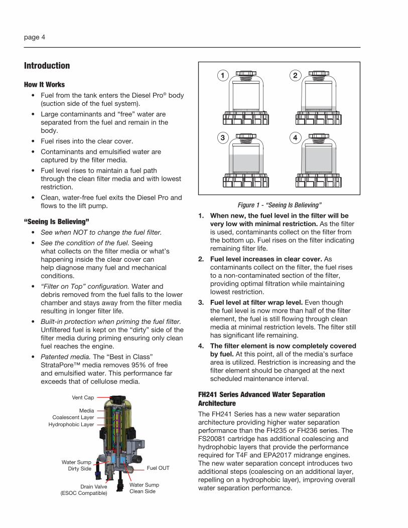
Figure 1 - “Seeing Is Believing”
1. When new, the fuel level in the filter will be very low with minimal restriction. As the filter is used, contaminants collect on the filter from the bottom up. Fuel rises on the filter indicating remaining filter life.
2. Fuel level increases in clear cover. As contaminants collect on the filter, the fuel rises to a non-contaminated section of the filter, providing optimal filtration while maintaining lowest restriction.
3. Fuel level at filter wrap level. Even though the fuel level is now more than half of the filter element, the fuel is still flowing through clean media at minimal restriction levels. The filter still has significant life remaining.
4. The filter element is now completely covered by fuel. At this point, all of the media’s surface area is utilized. Restriction is increasing and the filter element should be changed at the next scheduled maintenance interval.
FH241 Series Advanced Water Separation ArchitectureThe FH241 Series has a new water separation architecture providing higher water separation performance than the FH235 or FH236 series. The FS20081 cartridge has additional coalescing and hydrophobic layers that provide the performance required for T4F and EPA2017 midrange engines. The new water separation concept introduces two additional steps (coalescing on an additional layer, repelling on a hydrophobic layer), improving overall water separation performance.
Introduction
How It Works• Fuel from the tank enters the Diesel Pro® body
(suction side of the fuel system).
• Large contaminants and “free” water are separated from the fuel and remain in the body.
• Fuel rises into the clear cover.
• Contaminants and emulsified water are captured by the filter media.
• Fuel level rises to maintain a fuel path through the clean filter media and with lowest restriction.
• Clean, water-free fuel exits the Diesel Pro and flows to the lift pump.
“Seeing Is Believing”• See when NOT to change the fuel filter.
• See the condition of the fuel. Seeing what collects on the filter media or what’s happening inside the clear cover can help diagnose many fuel and mechanical conditions.
• “Filter on Top” configuration. Water and debris removed from the fuel falls to the lower chamber and stays away from the filter media resulting in longer filter life.
• Built-in protection when priming the fuel filter. Unfiltered fuel is kept on the “dirty” side of the filter media during priming ensuring only clean fuel reaches the engine.
• Patented media. The “Best in Class” StrataPore™ media removes 95% of free and emulsified water. This performance far exceeds that of cellulose media.
Media
Vent Cap
Coalescent LayerHydrophobic Layer
Water SumpDirty Side
Drain Valve(ESOC Compatible)
Fuel OUT
Water SumpClean Side

page 5
Service Kit InstallationThis system must be installed between the fuel tank and the transfer fuel pump. If approved by the manufacturer, this system can be used as the only fuel filter in the fuel system by removing the existing filter and heads, or by removing the filters only and replacing them with special Diverter Caps (sold separately - see Table 1).
Note: If the Diesel Pro® is used as the primary filter and a secondary filter is required, secondary filter life may be extended.
Table 1 - Diverter Caps
Diverter Cap Part Number
Required Filter Head Stud Size
Required Filter Head Seal ID
in (mm)
Required Filter Head Seal OD
in (mm)
3945182 S 1"-14 2.475 (62.865) 2.895 (73.533)
3945183 S 1"-14 3.225 (81.915) 3.435 (87.249)
3945184 S M16 x 1.5 2.475 (62.865) 2.895 (73.533)
3945185 S 3/4" x 16 2.475 (62.865) 2.895 (73.533)
3945186 S 7/8" x 14 2.475 (62.865) 2.895 (73.533)
� WARNING: When diesel fuel is circulated through an operating engine, it can become very hot. To prevent personal injury:
� Scalding hazard! Do not allow heated liquid fuel to come in contact with eyes or unprotected skin. Always allow the engine and fuel to cool to ambient temperature before replacing the fuel filter or performing service operations which could result in the spillage of fuel from the fuel system. If this is not possible, protective clothing (face shield, insulated hat, gloves, apron) must be worn.
� Fire hazard! Heated diesel fuel can form combustible vapor mixtures in the area around the fuel source. To eliminate the potential for fire, keep open flames, sparks or other potential ignition sources away from the work area, and do not smoke during filter replacement or service operations which could result in the escape of diesel fuel or fuel vapors.
� Inhalation hazard! Always perform engine or vessel fuel system maintenance in a well ventilated area that is kept free of bystanders.
� The ignition key must be in the OFF position.
Installing the Diesel Pro Service Kit1. With the engine shut down and at ambient
temperature, close the fuel shutoff valve (if equipped) and place a suitable container under the fuel filters.
2. Remove the primary fuel filter element assembly, sedimenter, and/or water separator. Drain the used element and dispose of it in an environmentally responsible manner, according to state and/or federal (EPA) or national recommendations. The fuel can be returned to the tank.
3. For a one-filter system, select the required secondary filter head diverter cap from those listed in Table 1. The required part number is determined by the size of the spin-on filter stud and the filter sealing surface diameter.
Install the diverter cap on the secondary filter head as follows:
a. Remove the secondary fuel filter element, drain and dispose of it in an environmentally responsible manner according to government regulations (i.e., state/province, federal, etc.). The fuel can be returned to the tank.
b. Lightly lubricate the seal on the top of the diverter cap with clean engine oil.
c. Thread the adapter onto the secondary filter stud and tighten by hand only.
d. Install the "Do Not Remove" sticker on the diverter cap.
4. Mount the Diesel Pro in the desired location using 3/8" (9.5 mm) Grade 8 hardware. Keep the following points in mind:
a. Mounting the Diesel Pro directly on the engine is NOT RECOMMENDED.
b. Mount vertically with the cover and element pointing up.
c. Make sure there is enough top and side clearance for the cover to be conveniently removed for filter replacement (1.5" (38.1 mm) minimum).
d. Bolt spacing is 5.25" (133.35 mm).
� CAUTION: The Diesel Pro® MUST be installed so that the Filter Element is above the "FULL" level of the fuel tank. If mounted below full tank level, a shut off valve will be required at the inlet to allow filter changes without overflow of fuel.
page 6
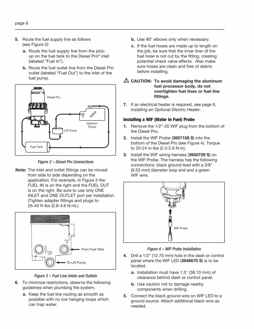
5. Route the fuel supply line as follows (see Figure 2):
a. Route the fuel supply line from the pick-up on the fuel tank to the Diesel Pro® inlet (labeled “Fuel In”).
b. Route the fuel outlet line from the Diesel Pro outlet (labeled “Fuel Out”) to the inlet of the fuel pump.
IN
Fuel Tank
Lift Pump
InjectionPump
Diesel Pro
Figure 2 – Diesel Pro Connections
Note: The inlet and outlet fittings can be moved from side to side depending on the application. For example, in Figure 3 the FUEL IN is on the right and the FUEL OUT is on the right. Be sure to use only ONE INLET and ONE OUTLET port per installation. (Tighten adapter fittings and plugs to 25-40 ft-lbs (2.8-4.6 N·m).)
HEATER
Figure 3 – Fuel Line Inlets and Outlets
6. To minimize restrictions, observe the following guidelines when plumbing the system.
a. Keep the fuel line routing as smooth as possible with no low hanging loops which can trap water.
b. Use 90° elbows only when necessary.
c. If the fuel hoses are made up to length on the job, be sure that the inner liner of the fuel hose is not cut by the fitting, creating potential check valve effects. Also make sure hoses are clean and free of debris before installing.
� CAUTION: To avoid damaging the aluminum fuel processor body, do not overtighten fuel lines or fuel line fittings.
7. If an electrical heater is required, see page 6, Installing an Optional Electric Heater.
Installing a WIF (Water In Fuel) Probe1. Remove the 1/2"-20 WIF plug from the bottom of
the Diesel Pro.
2. Install the WIF Probe (3957158 S) into the bottom of the Diesel Pro (see Figure 4). Torque to 20-24 in-lbs (2.3-2.8 N·m).
3. Install the WIF wiring harness (3950729 S) on the WIF Probe. The harness has the following connections: black ground lead with a 3/8" (9.53 mm) diameter loop end and a green WIF wire.
WIF Probe
Figure 4 – WIF Probe Installation
4. Drill a 1/2" (12.70 mm) hole in the dash or control panel where the WIF LED (3946670 S) is to be located.
a. Installation must have 1.5" (38.10 mm) of clearance behind dash or control panel.
b. Use caution not to damage nearby components when drilling.
5. Connect the black ground wire on WIF LED to a ground source. Attach additional black wire as needed.

page 7
6. Install WIF LED by pressing firmly into the drilled hole.
7. Connect the black ground lead with a 3/8" (9.53 mm) diameter loop end on the WIF wiring harness to ground source near the Diesel Pro (if applicable).
8. Connect green signal wire on WIF wiring harness to 4" (101.60 mm) green signal wire on WIF LED. Use additional green wire as needed.
9. Locate a 12 VDC or 24 VDC power source. Run a red wire from power source to the red wire on WIF LED. Add a 1 A in-line fuse (not included). (See Figure 5).
Figure 5 – WIF Wiring
Note: Use appropriate connectors to attach the wires. To test the WIF indicator, pour water into the body of the fuel processor until it covers the WIF probe. The WIF LED should illuminate.
Installing an Optional Electric HeaterAll units come with pre-drilled ports to allow for heaters/thermostats. The electric heaters available for the Diesel Pro® are 12 or 24 VDC Combo Thermo/Heaters and 120 VAC Heater. Electric heaters are optional and must be ordered separately (see Table 2).
Table 2 – Electric Heaters
Part Number Description
SP1312 Pre-Heater, 12 V, 195 W, WP Connector
SP1313 Pre-Heater, 24 V, 195 W, WP Connector
SP1314 Pre-Heater, 24 V, 195 W, Tyco Connector
3945121 S 120 VAC, 75 W Heater
3980208 S 120 VAC, 75 W Heater
1. If an Electric Heater is not already installed, remove the 7/8"-14 SAE (M16 x 1.5) o-ring heater plug from the Diesel Pro and install the Heater. Torque to 25-40 ft-lbs (2.8-4.6 N·m). (See Figure 6.)
Figure 6 - Heater Installation
2. Connect the Chassis harness to the Diesel Pro harness.
3. Attach the grounding eyelet to the chassis using a suitable 3/8" (9.5 mm) bolt.
4. Connect the Power Lead to the accessory side of the ignition switch. (Use of a 15 A fuse is recommended, but not included in the Diesel Pro kits. Use a relay if the ignition circuit will not handle a minimum of 15 A.) (See Figure 7.)
Figure 7 – Fuse and Relay Connections
Installing Optional Priming PumpsThe Fleetguard® Manual Priming Pump must be installed on the suction side of the fuel system.
� CAUTION: Do not over tighten the fuel hoses to the fittings to avoid damage to the Priming Pump or filter housing.

page 8
Installing with a New Diesel Pro® Produced Before August 30, 2010 or Any Diesel Pro Without a Bottom Bowl1. Disconnect the fuel inlet line coming from the
fuel tank to the Diesel Pro inlet.
2. Thread the “T” shaped plunger pump from kit #3979202 S (M18) or 3979203 S (M16) into the Fuel Inlet Port of the Diesel Pro.
3. Attach the fuel line from the fuel tank to the inlet of the Primer Pump.
4. Tighten to 25-40 ft-lb (39.9-54.3 N·m) of torque.
5. Remove the vent cap from the Diesel Pro.
6. Cycle the plunger of the Priming Pump until the Diesel Pro is full of fuel.
7. Hand tighten the vent cap.
8. Start the engine. When the lubrication system reaches normal operating pressure, increase the RPM for one minute. Slowly open the vent cap until the fuel level drops to one inch above the collar.
9. Check for fuel leaks.
10. Installation is complete.
INLETOUTLET
Fuel Tank
PrimingPump
(3979202 S or 3979203 S)
Note: Housings without the bottom bowl feature can use only the style priming pump shown here
Diesel Pro®
Covered under one or more of the following U.S. patents:4368716, 4428351, 5507942, RE37165 E,
and foreign patents or others pending.L4758
FH235 SeriesDiesel Pro®
Figure 8 – Installing the Priming Pump with a Diesel Pro Produced Before August 30, 2010
Installing with a New Diesel Pro® Produced After August 30, 2010 With a Bottom BowlWith the engine shut down and at ambient temperature, close the fuel shut-off valve (if equipped) and place a suitable container under the Diesel Pro and drain the fuel until empty.
1. Disconnect the fuel inlet line coming from the fuel tank to the Diesel Pro inlet.
2. Thread the Check Valve (3975109 S) from kit 3975111 S into the inlet port of the Diesel Pro.
3. Reconnect the fuel line from the fuel tank to the Diesel Pro inlet with Check Valve in place.
4. Remove the plug from the free Fuel Inlet Port.
5. Thread the Plunger Assembly (3975110 S) from kit 3975111 S into the free Fuel Inlet Port.
6. Tighten to 25-40 ft-lb (39.9-54.3 N·m) of torque.
7. Remove the vent cap from the Diesel Pro.
8. Cycle the plunger of the Priming Pump until the Diesel Pro is full of fuel.
9. Hand tighten the vent cap.
10. Start the engine. When the lubrication system reaches normal operating pressure, increase the Revolutions Per Minute (RPM) for one minute. Slowly open the vent cap until the fuel level drops to one inch above the collar.
11. Check for fuel leaks.
12. Installation is complete.
FuelLine
Fuel Tank
CheckValve
(3975109 S)
PlungerAssembly
(3975110 S)
Diesel Pro®
Figure 9 – Installing the Priming Pump with a Diesel Pro Produced After August 30, 2010
Filter Change Procedure1. Remove the vent cap and open the drain valve to
drain the fuel below the collar level.
2. Remove the collar using the Collar/Vent Cap Wrench (3944458 S) then remove the clear cover.
page 9
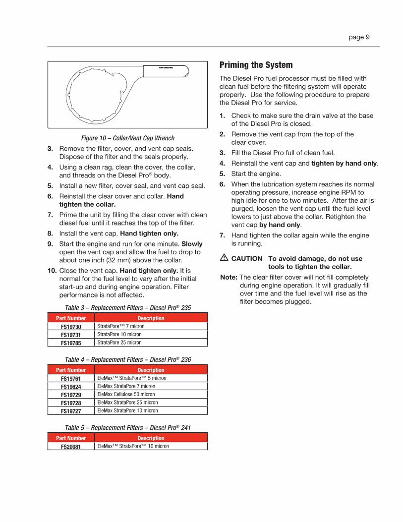
Figure 10 – Collar/Vent Cap Wrench
3. Remove the filter, cover, and vent cap seals. Dispose of the filter and the seals properly.
4. Using a clean rag, clean the cover, the collar, and threads on the Diesel Pro® body.
5. Install a new filter, cover seal, and vent cap seal.
6. Reinstall the clear cover and collar. Hand tighten the collar.
7. Prime the unit by filling the clear cover with clean diesel fuel until it reaches the top of the filter.
8. Install the vent cap. Hand tighten only.
9. Start the engine and run for one minute. Slowly open the vent cap and allow the fuel to drop to about one inch (32 mm) above the collar.
10. Close the vent cap. Hand tighten only. It is normal for the fuel level to vary after the initial start-up and during engine operation. Filter performance is not affected.
Table 3 – Replacement Filters – Diesel Pro® 235
Part Number Description FS19730 StrataPore™ 7 micron
FS19731 StrataPore 10 micron
FS19785 StrataPore 25 micron
Table 4 – Replacement Filters – Diesel Pro® 236
Part Number Description FS19761 EleMax™ StrataPore™ 5 micron
FS19624 EleMax StrataPore 7 micron
FS19729 EleMax Cellulose 50 micron
FS19728 EleMax StrataPore 25 micron
FS19727 EleMax StrataPore 10 micron
Table 5 – Replacement Filters – Diesel Pro® 241
Part Number Description FS20081 EleMax™ StrataPore™ 10 micron
Priming the SystemThe Diesel Pro fuel processor must be filled with clean fuel before the filtering system will operate properly. Use the following procedure to prepare the Diesel Pro for service.
1. Check to make sure the drain valve at the base of the Diesel Pro is closed.
2. Remove the vent cap from the top of the clear cover.
3. Fill the Diesel Pro full of clean fuel.
4. Reinstall the vent cap and tighten by hand only.
5. Start the engine.
6. When the lubrication system reaches its normal operating pressure, increase engine RPM to high idle for one to two minutes. After the air is purged, loosen the vent cap until the fuel level lowers to just above the collar. Retighten the vent cap by hand only.
7. Hand tighten the collar again while the engine is running.
� CAUTION To avoid damage, do not use tools to tighten the collar.
Note: The clear filter cover will not fill completely during engine operation. It will gradually fill over time and the fuel level will rise as the filter becomes plugged.

page 10
Suggested Preventive MaintenanceWeekly – Drain water
1. Turn off the engine and open the vent cap.
2. Place a suitable eight ounce plastic or metal container under the drain valve at the base of the Diesel Pro and open the valve.
3. Water will flow into the container. When the fuel begins to flow out the drain, close the drain valve. Drain the least amount of fuel possible.
4. Hand tighten the vent cap.
5. Start the engine. Raise the RPM for one minute to purge the air from the system.
Every Filter Change – Change the cover and vent cap o-rings (included with the filter service kit).
Every 12 Months – Check all electrical connections for corrosion. Check all fuel fittings for leaks.
Extreme winter or salt corrosion environments may require lubrication of the top collar threads with Loctite® 76747 anti-seize every 180 days.
Servicing the Check Valve Assembly1. Remove the vent cap and open the drain valve,
drain the Diesel Pro® completely.
2. Remove the collar, then remove the clear cover.
3. Remove the filter, cover and vent cap seals. Dispose of filters and seals properly.
4. Using a clean shop rag, clean the cover, the collar and threads on the Diesel Pro body.
5. Remove the check valve assembly (see Figure 11).
Figure 11 – Removing the Check Valve Assembly
6. Clean and inspect the check valve body (Replace if the valve or the seat show any visible signs of damage)
7. Replace the check valve assembly into the Diesel Pro body (torque to 12-14 ft-lbs).
8. Install a new filter, cover seal and vent cap seal.
9. Reinstall the clear cover and collar. Tighten the collar.
10. Prime the Diesel Pro by filling the clear cover with clean diesel fuel until it reaches the top of the filter.
11. Install the vent cap.
12. Start the engine and run for one minute. Slowly open the vent cap and allow the fuel level to drop to about one inch above the collar.
13. Close the vent cap. Hand tighten only.
TroubleshootingEvery Diesel Pro is factory tested for leaks and is marked with a traceable number to show that it has passed production testing.
Most field issues associated with leaks are related to loose fittings. These leaks are easily eliminated by checking and torquing the fuel fittings in the area of the leak.
Some fittings may also require the application of liquid Teflon® sealer.
Note: All suction side fuel filters experience bubbles. It is normal to see champagne size bubbles in the Diesel Pro at the Diesel Pro outlet or at the lift pump.

page 11
Air LeakAir bubbles will be visible in the clear cover of the Diesel Pro if the leak originates from the fuel tank up to the fuel filter. The following is a quick test to isolate the air leak source.
Bubbles Visible:
1. Remove the Diesel Pro inlet hose.
2. Install a jumper hose from the Diesel Pro to the fuel tank (through the fill cap) or to a container of fuel.
3. Start the engine. If this eliminates the air bubbles, the air source is at the fuel tank fittings or hose connections.
4. Tighten all fittings and connectors
5. Retest
If air bubbles persist, the air source is on the Diesel Pro side of the system:
1. Tighten all fittings on the Diesel Pro.
2. Tighten the collar.
3. If the drain valve is suspected, install a plug in place of the drain valve (for test purposes only).
If air bubbles continue to persist, test as follows:
1. Remove the Diesel Pro® from the chassis.
2. Plug the fuel inlet port. Do not remove filter, cover/collar, vent cap, drain valve and/or check valve. If the Diesel Pro is equipped with a preheater, do not remove the preheater.
3. Apply 15 PSI of air pressure at the fuel outlet. Immerse the Diesel Pro in a tank of water and look for air bubbles.
4. Correct the source of the air leak and retest.
Bubbles Not Visible
1. If there are symptoms of sucking air (indicated by engine loping/rough running performance/power loss, etc.) and there are no bubbles in the clear cover, the air leak is either at the Diesel Pro outlet fitting, vent cap o-ring, the lift pump inlet connection, or the fuel hose/connections to the lift pump.
2. Inspect and tighten fittings as needed.
Excessive RestrictionIf the fuel level is at the top of the filter, replace the fuel filter. The Diesel Pro will not cause excess system restriction if the fuel level is below the top of the filter.
Loss of PrimeWhen air is introduced into the fuel system, (for example, when draining water from the Diesel Pro or when replacing the fuel filter) a check valve is needed to keep the fuel system primed from the Diesel Pro back to the fuel tank. A check valve is standard with all Diesel Pros.
To test for proper check valve operation:
Remove the fuel inlet hose and open the vent cap. Fuel should not flow out of the Diesel Pro, although a slight seepage of fuel is normal.
If fuel drains back to the fuel tank, remove the check valve assembly:
1. Disassemble the check valve assembly. Clean and inspect.
2. Replace the assembly if any cuts, grooves or nicks are evident in the valve or valve seat.
3. Reinstall the check valve assembly.

page 12
Ordering Information
Diesel Pro® 235
Housing Part Number
Filter Element Heater WIF Cover Fuel FlowFuel In & Fuel Out
Port SizePriming Pump
FH23500 FS19730 N/A N/A Short In Right/Out Left 7/8"-14 No
FH23501 FS19730 24 VDC, 195 W N/A Short In Right/Out Left 7/8"-14 No
FH23502 FS19730 12 VDC, 195 W N/A Short In Right/Out Left 7/8"-14 No
FH23503 M* FS19785 N/A Yes Short In Right/Out Left M16 No
FH23504 M* FS19785 24 VDC, 195 W Yes Short In Right/Out Left M16 No
FH23506 FS19731 24 VDC, 195 W Yes Short In Right/Out Left 7/8"-14 No
FH23508 FS19731 N/A Yes Short In Right/Out Left 7/8"-14 No
FH23509 M* FS19731 N/A Yes Short In Right/Out Left M16 No
FH23510 FS19731 12 VDC, 195 W Yes Short In Right/Out Left 7/8"-14 No
FH23515 M* FS19731 N/A (open) Yes ShortIn Right/Out Left
(all open)M16 Yes
FH23517 FS19730 N/A N/A Short In Right/Out Left 3/8" NPTF No
FH23518 M* FS19731 24 VDC, 195 W Yes Short In Right/Out Left M16 No
* Metric units - not available in EuropeNote: The Diesel Pro 235 can be upgraded to a Diesel Pro 236 by replacing the cover with Fleetguard part number 3973506 S and the filter with Fleetguard
part number FS19624. For more information, contact Fleetguard Customer Assistance.
Diesel Pro® 236Housing Part
NumberFilter Element Heater WIF Cover Fuel Flow
Fuel In & Fuel Out Port Size
Priming Pump
FH23600 FS19624 N/A N/A Tall In Right/Out Left 7/8"-14 SAE No
FH23601 FS19624 12 VDC, 195 W N/A Tall In Right/Out Left 7/8"-14 SAE No
FH23602 FS19624 24 VDC, 195 W N/A Tall In Right/Out Left 7/8"-14 SAE No
FH23603 FS19728 N/A Yes Tall In Right/Out Left 7/8"-14 SAE No
FH23604 M* FS19728 N/A Yes Tall In Right/Out Left M16 No
FH23605 M* FS19728 24 VDC, 195 W Yes Tall In Right/Out Left M16 No
FH23606 M* FS19728 24 VDC, 195 W Yes Tall In Right/Out Left M16 No
FH23607 FS19727 N/A Yes Tall In Right/Out Left 7/8"-14 SAE No
FH23608 M* FS19727 N/A Yes Tall In Right/Out Left M16 No
FH23610 FS19728 N/A N/A Tall In Right/Out Left 7/8"-14 SAE No
FH23616 M** FS19624 N/A Yes Tall In Right/Out Left M16 No
FH23617 M* FS19728 N/A (open) Yes Tall In Right/Out Left (all open) M16 Yes
FH23618 FS19727 N/A Yes Tall In Right/Out Left 7/8"-14 SAE Yes
FH23621 M** FS19624 12 VDC, 195 W Yes Tall In Right/Out Left M16 No
FH23622 M** FS19624 24 VDC, 195 W Yes Tall In Right/Out Left M16 No
FH23623 M* FS19624 N/A Yes Tall In Right/Out Left M16 Yes
FH23624 M* FS19728 12 VDC, 195 W Yes Tall In Right/Out Left M16 No
FH23625 M* FS19728 24 VDC, 195 W Yes Tall In Right/Out Left M16 Yes
FH23627 FS19728 N/A Yes Tall In Right/Out Left 3/8" NPTF No
FH23696*** FS19624 N/A Yes Tall In Right/Out Left M16 No
* Metric units - available outside North America except Europe** Metric units available in Europe*** Includes drain valve with hose barb connection

page 13
SpecificationsSpecification Diesel Pro® 235 Diesel Pro® 236 Diesel Pro® 241
Height Overall 10.75" (273.1 mm) 13.0" (330.2 mm) 13.36" (339.5 mm)
Depth Overall 5.8" (147.3 mm) 5.8" (147.3 mm) 5.8" (147.3 mm)
Width, max 6.22" (158.0 mm) 6.22" (158.0 mm) 6.22" (158.0 mm)
Mount Bracket Centersor Rear Mount Centers
5.25" (133.4 mm)3.0" (76.2 mm)
5.25" (133.4 mm)3.0" (76.2 mm)
5.25" (133.4 mm)3.0" (76.2 mm)
Weight (Dry) 5 lbs (2.27 kg) 5 lbs (2.27 kg) 6-7 lbs (3.72-3.17 kg)
Fuel Connections (Inlet) 7/8"-14 (M16 x 1.5) 7/8"-14 (M16 x 1.5) 7/8"-14 (M16 x 1.5)
Fuel Connection (Outlet) 7/8"-14 (M16 x 1.5) 7/8"-14 (M16 x 1.5) 7/8"-14 (M16 x 1.5)
Fuel Capacity (w/o filter) 70.2 fl oz (1995 mL) 70.2 fl oz (1995 mL) 70.2 fl oz (1995 mL)
Operation Fuel Flow Rate 60 gal/h (230 L/h) 90 gal/h (341 L/h) 60 gal/h (227 L/h)
Recommended Applications Light and Medium Duty Engines Light and Medium Duty Engines Light and Medium Duty Engines
Water Trap Capacity 15.2 fl oz (450 mL) 15.2 fl oz (450 mL) 15.2 fl oz (450 mL)
Filter Service Clearance Min. 1.5" (38.1 mm) Min. 1.5" (38.1 mm) Min. 3.5" (88.9 mm)
Mounting Bracket Cast in Head Cast in Head Cast in Head
Electrical Heater12 VDC, 195 W, 8.5 A ± 0.8 A24 VDC, 195 W, 4.5 A ± 0.5 A120 VAC, 75 W, 0.64 A ± 0.06 A
12 VDC, 195 W, 8.5 A ± 0.8 A24 VDC, 195 W, 4.5 A ± 0.5 A120 VAC, 75 W, 0.64 A ± 0.06 A
12 VDC, 195 W, 8.5 A ± 0.8 A24 VDC, 195 W, 4.5 A ± 0.5 A120 VAC, 75 W, 0.64 A ± 0.06 A
Fuel Types Compatible for use with Diesel #1, Diesel #2, Kerosene, Biodiesel, and JP8
Specifications subject to change without notice.
Ordering Information
Diesel Pro® 241
Housing Part Number
Filter Element Heater WIF Cover Fuel FlowFuel In & Fuel Out
Port SizePriming Pump
FH24100 FS20081 N/A Yes Tall In Left/Out Left M16 Yes
FH24101 FS20081 N/A Yes Tall In Right/Out Left 7/8"-15 UNF Yes
FH24102 FS20081 N/A Yes Tall In Right/Out Left 3/8" NPTF Yes
FH24103 FS20081 N/A Yes Tall In Right/Out Left M16 Yes
FH24104 FS20081 24 VDC, 195 W Yes Tall In Left/Out Left M16 Yes
FH24105 FS20081 24 VDC, 195 W Yes Tall In Right/Out Left M16 Yes
FH24106 FS20081 24 VDC, 195 W Yes Tall In Right/Out Left M16 Yes
FH24107 FS20081 24 VDC, 195 W Yes Tall In Right/Out Left M18 Yes
FH24108 FS20081 120 VDC, 75 W Yes Tall In Right/Out Left 3/8" NPTF Yes
FH24110 FS20081 N/A No Tall In Right/Out Left 7/8"-14 UNF No
FH24111 FS20081 N/A No Tall In Right/Out Left M16 No
FH24112 FS20081 N/A Yes Tall In Right/Out Left 7/8"-14 UNF No
FH24113 FS20081 N/A Yes Tall In Right/Out Left M16 No
FH24114 FS20081 24 VDC, 195 W Yes Tall In Right/Out Left M16 No
page 14
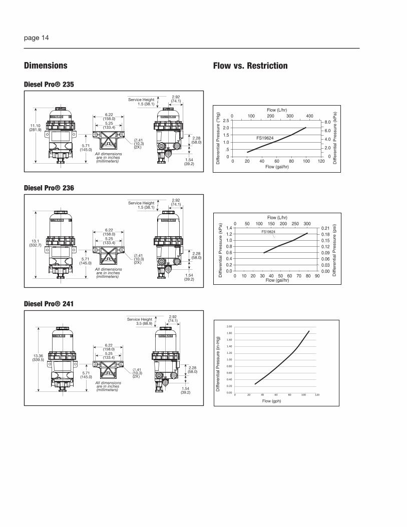
Dimensions
Diesel Pro® 235
All dimensionsare in inches(millimeters)
∅.41(10.3)(2X )
5.25(133.4)
6.22(158.0)
11.10(281.9)
2.28(58.0)
1.54(39.2)
2.92(74.1)Service Height
1.5 (38.1)
5.71(145.0)
Diesel Pro® 236
All dimensionsare in inches(millimeters)
∅.41(10.3)(2X )
5.25(133.4)
6.22(158.0)
13.1(332.7)
2.28(58.0)
1.54(39.2)
2.92(74.1)Service Height
1.5 (38.1)
5.71(145.0)
Diesel Pro® 241
All dimensionsare in inches(millimeters)
.41(10.3)(2X )
5.25(133.4)
6.22(158.0)
13.36(339.5)
2.28(58.0)
1.54(39.2)
2.92(74.1)Service Height
3.5 (88.9)
5.71(145.0)
0.00
0.20
0.40
0.60
0.80
1.00
1.20
1.40
1.60
1.80
2.00
0 20 40 60 80 100 120
Diff
eren
tial P
ress
ure
(in-H
g)
Flow (gph)
0.00 2010 4030 50 60 8070 90
0.20.40.60.8
1.21.0
1.40.180.21
0.030.00
0.060.09
0.150.12
0 10050 200 250150 300
Flow (gal/hr)
Flow (L/hr)
FS19624
Diff
ere
ntia
l Pre
ssure
(psi
)
Diff
ere
ntia
l Pre
ssure
(kP
a)
2.5
2.0
1.5
1.0
.5
0
Diff
ere
ntia
l Pre
ssure
("H
g)
0 20 40 60 80 100 120Flow (gal/hr)
FS19624
Diff
ere
ntia
l Pre
ssure
(kP
a)
8.0
6.0
4.0
2.0
0
Flow (L/hr)0 100 200 300 400
Flow vs. Restriction

page 15
For more information, visitcumminsfiltration.comLT36147 – Rev. 8©2017 Cummins Filtration Inc.Printed in the U.S.A.
Revision Date Description
7 10/10/2017 Added FH241 Series
8 11/1/2017
SP1312 was 3972254 SSP1313 was 3976892 SSP1314 was 3976891 SHeaters 195 W was 250 W and 150 W3976891 S, 250 W is obsolete2 VDC, 195 W, 8.5 A ± 0.8 A was 12 VDC, 150 W, 8.5 A ± 0.8 A24 VDC, 195 W, 4.5 A ± 0.5 A was 24 VDC, 150 W, 4.5 A ± 0.5 AAdded Flow vs Restriction graphsAdded FH23696 to Ordering Information