lt1275x3 ncat service guide
TRANSCRIPT

NCATAsphalt Content Furnace
Service Manual
LT1275X3 • 2/13/04

2
Table of Contents
Introduction..........................................................................................................................................................5What is an NCAT Asphalt Test Furnace? ....................................................................................................5Why Test Asphalt? ........................................................................................................................................5Why Improve the Existing Method of Asphalt Testing? ................................................................................5Barnstead International’s Involvement..........................................................................................................6How Does the NCAT Work? ........................................................................................................................6
Unpacking and Installation ..................................................................................................................................7Electrical Specifications ................................................................................................................................7Site Selection................................................................................................................................................9Power Requirements ....................................................................................................................................9Exhaust Installation Tips ..............................................................................................................................9Installation Drawings ..................................................................................................................................11
Balance ............................................................................................................................................................13OHAUS vs. SETRA ....................................................................................................................................13SETRA Balance Replacement....................................................................................................................13OHAUS Fuse Location ..............................................................................................................................14OHAUS Display Board................................................................................................................................14OHAUS and SETRA Ribbon Cables ..........................................................................................................14Replacement Parts ....................................................................................................................................14
OHAUS Balance................................................................................................................................................15Installation ..................................................................................................................................................15Balance Control Port Hole Location ..........................................................................................................17OHAUS Time and Date Set Procedure ......................................................................................................18Resetting the User Variables of an OHAUS Balance ................................................................................20OHAUS Balance Calibration ......................................................................................................................25
SETRA Balance ................................................................................................................................................27SETRA Balance Installation........................................................................................................................27Balance Control Port Hole Location ..........................................................................................................29SETRA Time and Date Set Procedure ......................................................................................................30
Resetting Variables of a SETRA Balance to Factory Default ................................................................32SETRA Balance Calibration........................................................................................................................33
Error Conditions ................................................................................................................................................35OHAUS Balance ........................................................................................................................................35SETRA Balance ..........................................................................................................................................36
Printer ..............................................................................................................................................................37Thermal Paper Storage ..............................................................................................................................37RS232 Connection Information ..................................................................................................................37Printer Change (Production) ......................................................................................................................38Troubleshooting ..........................................................................................................................................39
Software ............................................................................................................................................................41History ........................................................................................................................................................41SC859X1 Rev. 1 Software EPROM............................................................................................................43Installation ..................................................................................................................................................45Ordering Information ..................................................................................................................................47
Procedures ........................................................................................................................................................48Amendment ................................................................................................................................................48Definition ....................................................................................................................................................48

Output ..............................................................................................................................................................59Bitumen Ratio ............................................................................................................................................59
Glossary ............................................................................................................................................................60Errors ..............................................................................................................................................................63
Red Display (Furnace)................................................................................................................................63Green Display (Balance) ............................................................................................................................66NCAT Troubleshooting with No Error Codes Displayed ............................................................................68Aggregates..................................................................................................................................................72Negative Air Pressure ................................................................................................................................72Displayed Letters/Numbers ........................................................................................................................74
Equipment Test Procedure................................................................................................................................81Removal of the Control Assembly (Bottom Section) in the 1087 and 1275 Series NCAT ........................811087 Series Back Wall Insulation Removal................................................................................................88Heating Elements ......................................................................................................................................89Element Part Numbers and Cold Resistance ............................................................................................95Thermocouples ..........................................................................................................................................98Solid State Relays ....................................................................................................................................101Keypad......................................................................................................................................................104
Maintenance ....................................................................................................................................................110Lift Test Procedure ....................................................................................................................................110Cleaning Procedure for NCAT ..................................................................................................................111Chamber Temperature Verification/Calibration ........................................................................................112Balance Calibration ..................................................................................................................................115
Drawings..........................................................................................................................................................116
3
TABLE OF CONTENTS

4

5
What is an NCAT Asphalt TestFurnace?The NCAT Asphalt Content Furnace is a unitized furnace,electronic weighing system, and exhaust air filtrationmechanism combined into one system. The system wasdeveloped by a team of Barnstead International engineersin conjunction with the National Center for AsphaltTechnology (hence the name NCAT) at Auburn University.The NCAT furnace was designed as an improvement overthe existing solvent method of determining the binder con-tent in asphalt paving materials.
Why Test Asphalt?Hot mix asphalt used for roads and highways has to beincredibly durable, withstanding not only the rigors ofheavy truck and car traffic, but also the temperatureextremes of tropical summers and arctic winters.
Why Improve the ExistingMethod of Asphalt Testing?Existing testing methods are extremely time consumingand difficult to perform properly.
Introduction

Barnstead International’sInvolvementBecause the NCAT researchers at Auburn Universitydecided that their new test method would use high tem-perature to separate the asphalt from the aggregate in theasphalt mix, they needed a company that specializedbenchtop high temperature laboratory furnaces.
How Does the Asphalt ContentFurnace Work? A known weight of asphalt mix is placed in the NCAT fur-nace chamber. The furnace then burns away the binderuntil only the stones remain. The automatic weighingsystem incorporated into the unit monitors the reduction inweight of the sample as the binder burns off until theweight change stops (meaning all the binder has beenburnt away and only stones remain). The software withinthe unit then calculates the percent of binder within theasphalt mix. All of this is included on a paper printout bya small built-in strip recorder so that the lab techniciancan confirm that the tested sample of asphalt did meetaccepted quality standards. All of this may sound simple,but it isn’t. An especially difficult technological problemwas how to eliminate the black soot that would normallybillow out of the furnace exhaust as the asphalt binderburned away. Our engineers developed a special ceram-ic filtration/burner system so effective that the outsideexhaust is essentially invisible and meets all guidelinesfor emissions set by the Environmental ProtectionAgency. This solution was so innovative that the U.S.Patent Department has granted several patent claims toBarnstead International.
6
INTRODUCTION

7
Electrical SpecificationsModel # Voltage Amperage Watts PhaseF85930 240Vac 27 Amps 6379 50/60Hz, SingleF85930 220Vac 20 Amps* 4879 50/60Hz, SingleF85938 208Vac 28 Amps 5757 50/60Hz, SingleF85930-33 240Vac 27 Amps 6379 50/60 Hz, Single
*Model # F85930 units are configured for a 27 Amp supply when shipped from the factory. You have theoption of re-configuring the wiring at the back of the furnace for 20 amps. Please refer to the owner/operatormanual for instructions on how to re-wire the unit for the lower amperage configuration. Typically, a 20-ampconfiguration is used for mobile laboratory installations where the power supplies may be limited. Units con-figured for 20 amps will heat and process samples at a slower rate.
• NCAT furnaces are not supplied with a power cord or plug and must be wired either directlythrough a conduit system or by a customer supplied power cord and plug. Electrical wiring shouldconform to local electrical code requirements. Please consult with a certified electrician for electricalconnection.
• NCATs sold in the 208V version should not be connected to 240V power supply. Damage to electri-cal components in the furnace will occur.
• NCATs sold in the 240V version should not be connected to 208V power supply. Damage to electri-cal components in the furnace will occur.
• Buck/Boost low voltage isolation transformers are an electrical device that has the ability to step upa 208V power supply to 240V or step down a 240V power supply to 208V. Buck/Boost transformersare available at Barnstead International (P/N TNX122) or can be purchased at local electrical retailstores.
• Recommended buck/boost transformer ratings (TNX122):
MFR: Jefferson ElectricMFR Model: 216-1241-000Ratings: .75 kVA
Single Phase (50/60Hz)120/240 Volts16/32 Volts
Unpacking and Installation

8
UNPACKING AND INSTALLATION
Parts Shipped in Chamber:(8) JSX122 - Balance/Hearth Plate Ceramic Support Tubes
Parts Shipped in Accessory Box (Located on top of unit - not pictured)PHX4 - Hearth Plate(2) FZX47 - Fuses(2) FZX53 - Fuses(2) FZX61 - FusesME859X1 - BalanceLT1275X1 - Manual
Barnstead International “packs” a chamber to transport an NCAT from one location to another, preventing damage.

Site Selection• The NCAT should be mounted on a sturdy level
surface, capable of supporting the weight of thefully assembled furnace (Approximately 300pounds).
• Allow a minimum space of 6 inches between theNCAT outer casing and any vertical surfacessuch as the walls of the building for airflowrequirements and heat escape. The chamberdoor must be permitted to swing freely to allowloading and unloading of the chamber.
• Locate the furnace so that you can direct thefurnace emissions through ducting to a fumehood or other appropriate ventilation systems.We recommend an exhaust length of not morethan 10 feet.
Power RequirementsThe NCAT units are not supplied with a power cord due tothe large amperage draw. Please consult with a certifiedelectrician to have the NCAT hardwired or an appropriatepower cord and receptacle installed in your facility.Electricians will ensure compatibility among furnace spec-ifications, power source and ground code requirements.
Exhaust Installation Tips• See Installation tips in the Owner/Operator man-
uals for more information and/or refer to installa-tion drawings for additional information on instal-lation.
• Minimize bends in exhaust tubing as much aspossible. (Rule of thumb: Only one 90° bendallowed in exhaust tubing 10 feet in total length.)
• Exhaust exiting the furnace port may reach tem-peratures as high as 270°C. Keep all flammablematerial a safe distance from the furnace.
• 3-inch outside diameter, flexible stainless steeltubing works best for exhaust duct-work.
9
INSTALLATION
NoteThis manual does not include allinformation necessary to properlyinstall an NCAT. Please refer toowner/operator manual.

Available from Barnstead International, P/NTU859X1.
• Install rock-wall cloth rated to handle tempera-tures up to 270°C to insulate the exhaust tubingpassing through ceiling ducts.
• Do not use exhaust tubing less than 3 inches indiameter.
• Do not use galvanized tin tubing or double walltin tubing.
• Do not connect the NCAT exhaust port directlyto an external fan with a rating of more than 60CFM. This will create a negative airflow in theexhaust system. The blower motor in the NCAT is rated at 65CFM and will provideenough power for emission up to approximately10 feet.
10
INSTALLATION

11
INSTALLATION

12
INSTALLATION

The original NCAT (Series 859 & 945) were all manufac-tured with an OHAUS balance, model GT8000. Designchanges still found OHAUS balances being used in the1087 series until February 1998, in which a manufacturingchange from OHAUS to SETRA was completed.
OHAUS vs. SETRA• The physical appearance between both scales
is different, with the housing of the OHAUS bal-ance being brown or tan in color and housing ofthe SETRA being gray or silver.
• OHAUS balances are a 240 VAC powered scaleand the SETRA are a 15 VDC powered scale.
• The display board for the SETRA is mated witha load cell or silver colored base. Whereas theOHAUS load cells and display boards can beinterchanged. (A 6 digit number can be found onthe SETRA load cell and on the mated displayboard.)
• The SETRA balance does not contain thenumerous user variables found in the OHAUS,making functions, such as resetting the time ordate and calibrating the SETRA much easier.
• The SETRA does not require a special calibra-tion plate, as does the OHAUS. (The hearthplate can be left in the chamber, when calibrat-ing the SETRA.)
SETRA Balance ReplacementWhen replacing SETRA balances, the balance (load cell)and display board MUST be changed out as a matchedpair. Locate the decal on the back of the balance (loadcell) with a 6 digit number. Locate the decal on the dis-play board with the 6-digit number. Ensure the numberson both parts match. If they do not match, the balancewill not function properly. When customers returnSETRA balances, they MUST return the matching dis-play board for warranty coverage.
13
Balance
OHAUS balance and display board
SETRA balance and display board
14
BALANCE
Replacement PartsPart Number DescriptionME859X1 SETRA upgrade kit. For customers wanting to update their NCAT from the OHAUS
to the SETRA balance. This kit includes all the necessary wire harnesses needed to connect a new SETRA balance and installation instructions.
ME1087X1/C New SETRA balance for warranty situations. (This part number was set up for customers with SETRA balances that fail within warranty.)
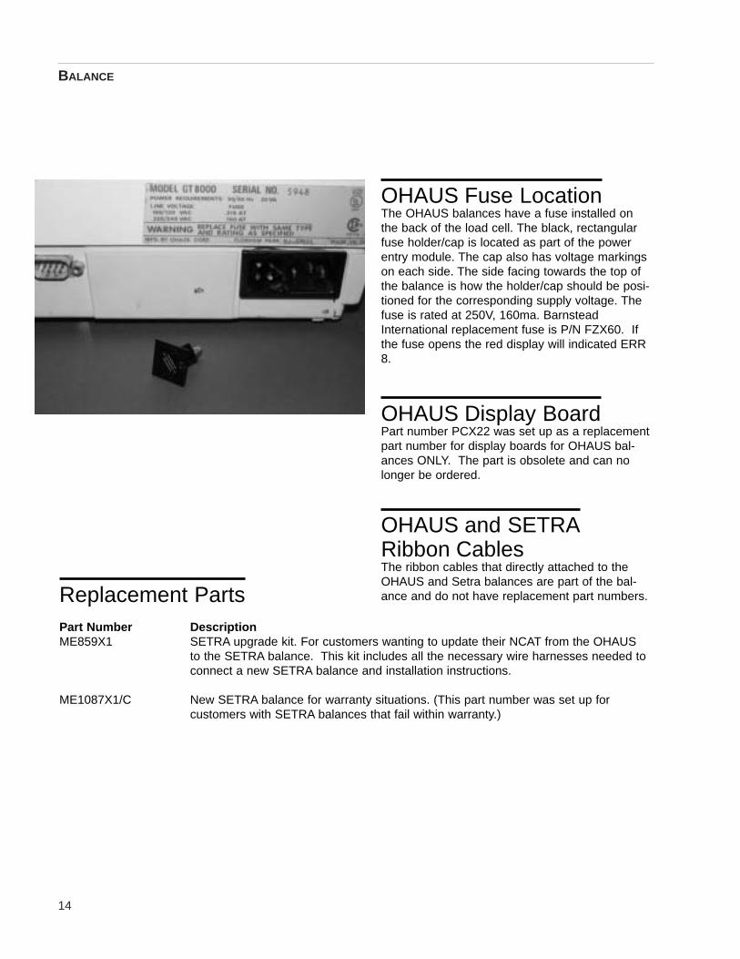
OHAUS Fuse LocationThe OHAUS balances have a fuse installed onthe back of the load cell. The black, rectangularfuse holder/cap is located as part of the powerentry module. The cap also has voltage markingson each side. The side facing towards the top ofthe balance is how the holder/cap should be posi-tioned for the corresponding supply voltage. Thefuse is rated at 250V, 160ma. BarnsteadInternational replacement fuse is P/N FZX60. Ifthe fuse opens the red display will indicated ERR8.
OHAUS Display BoardPart number PCX22 was set up as a replacementpart number for display boards for OHAUS bal-ances ONLY. The part is obsolete and can nolonger be ordered.
OHAUS and SETRARibbon CablesThe ribbon cables that directly attached to theOHAUS and Setra balances are part of the bal-ance and do not have replacement part numbers.

InstallationThe OHAUS Balance (GT8000) operates on 208Vac or240Vac (full potential line voltage). The balance is config-ured for supply voltage that corresponds with the NCATupon production at Barnstead International.
OHAUS balances were used in production from 1995 to1998 and are currently sold as replacements only.
1. Ensure that both the balance and the furnaceare disconnected from the power supply.Remove the four screws along the top of thefront control panel securing the control panel tothe lower case of the furnace.
2. Open the lower control panel by carefully swing-ing the control panel down (hinged).
3. Inside the lower control assembly, observe thesuspended table supported by four aluminumrods. The balance will be supported by thistable. Vacuum the table if dust, etc., appear onit.
4. Mount the platform support plate on the bal-ance. Note the four pins on the support plate.These will retain the ceramic support tubes,which will project into the furnace chamber aftermounting.
5. Orient the balance so that the front of the bal-ance faces the back of the furnace. Run thecable attached to the front of the balance underthe balance, so that the unattached end of thecable emerges from beneath the back of thebalance.
6. Slide the balance front-first onto the suspendedtable beneath the furnace chamber.
7. Position the balance so that the pins on the plat-form support plate are directly beneath the fourtube ports in the bottom of the furnace chamber.
8. Plug the balance’s power cord (the black, three-pronged female plug) into the socket on the rear
15
OHAUS Balance

16
of the balance. Plug the nine-pin ribbon cablefemale socket from the controller into the corre-sponding socket on the back of the balance.Plug the 13 pin socket on the display cable (thecable from the front of the balance runningbeneath the balance) into the 13 pin connectorlocated on the lower right-hand edge (as youface the unit) of the balance display board(mounted on the right-hand side of the front con-trol panel).
9. Open the furnace door. Mount the four ceramicsupport tubes through the tube ports located inthe bottom of the furnace chamber. Adjust theposition of the balance until the four ceramicsupport tubes are seated on the appropriatepins on the balance plate. Finely adjust theposition of the balance until the tubes are cen-tered in their ports, but not touching the sides ofthe ports,
10. Mount the hearth tray on the four ceramic sup-port tubes. Place the smooth side of the hearthtray down, with the ridges on the top of thehearth tray running from the front to the back ofthe furnace chamber.
11. Close the lower case by returning the controlpanel to its original position. Secure the controlpanel with the four screws you removed in step1.
OHAUS BALANCE

17
Balance Control Port Hole LocationThere are 4 holes strategically placed on the front of the control panel, between the green display and the reddisplays. These holes are used to access and adjust the balance variables. Use an appropriate sized tool orpaper clip to access balance keys through the port holes in the control panel. Reference the sketch of thecontrol panel for location/identification of balance control port holes which will need to be accessed to performbalance time/date setting, balance resetting, and balance calibration procedures.
OHAUS BALANCE
PRINT Button MODE Button OFF Button ON Button
Chamber Temp Percent Loss Elapsed Time
Balance Display
Control Panel Sketch

OHAUS Time and Date SetProcedureThe balance supplies the time & date to the microproces-sor of the NCAT. For ease of record keeping and to allowthe microprocessor to function properly, please ensurethe time and date are set appropriately.
The balance is shipped with the time & date set to CentralDaylight Time or Central Standard Time, depending onthe time of the year the balance is purchased. If you wishto adjust these settings for local time, please follow theoutlined procedure.
Note: The OHAUS balance must be set up for US datesettings and EURO time (24 hour format) settings or it willnot communicate with microprocessor in the NCAT cor-rectly.
1. Power down the NCAT furnace using the greenpower switch. Press and the hold the number“4” key on the keypad. While holding down the“4” key, power up the NCAT using the greenpower switch. Hold the “4” key until you hearthe NCAT beep. Release the “4” key.
2. Press and hold the balance ON button. Releasewhen “Menu” appears on the balance display.
3. “Menu” will automatically change to “Cal”. When“Cal” is displayed, repeatedly press the MODEbutton until “Setup” is displayed.
4. Press the ON button. “Reset” will be displayed.
5. Repeatedly press the MODE button until “Time”is displayed.
6. Press the ON button. “Type” will be displayed.
7. Press the ON button. “US” will be displayed.
8. Press the MODE button. “Euro” will be dis-played.
9. Press the ON button. “Type” will be displayedagain.
18
OHAUS BALANCE

10. Press the MODE button. “Set” will be displayed.
11. Press the ON button. The display will indicatetime with the first two digits (hours) flashing.
12. Repeatedly press (or press and hold to scroll)the MODE button until the current hour (24 hourclock) is displayed.
13. Press the ON button. The last two digits (min-utes) will flash.
14. Repeatedly press (or press and hold to scroll)the MODE button until the current minute is dis-played.
15. Press the ON button. “Set” is displayed.
16. Press the MODE button. “End, Time” will be dis-played.
17. Press the ON button. “Time” will be displayedagain.
18. Press the MODE button. “Date” will be dis-played.
19. Press the ON button. “Type” will be displayed.
20. Press the ON button. “US” will be displayed.
21. Press the ON button. “Type” will be displayedagain.
22. Press the MODE button. “Set” will be displayed.
23. Press the ON button. The display will not indi-cate the date with the first two digits (month)flashing.
24. Repeatedly press (or press and hold to scroll)the MODE button until the current month is dis-played.
25. Press the ON button. The second two digits(date) will flash.
19
OHAUS BALANCE

26. Repeatedly press (or press and hold to scroll)the MODE button until the current date is dis-played.
27. Press the ON button. The last two digits (year)will flash.
28. Repeatedly press (or press and hold to scroll)the MODE button until the current year is dis-played.
29. Press the ON button. “Set” will be displayed.
30. Press the MODE button. “End, Date” will be dis-played.
31. Press the ON button. “Date” will be displayed.
32. Repeatedly press the MODE button until “End,Setup” is displayed.
33. Press the ON button. “Setup” will be displayed.
34. Press the MODE button until “End, Menu” is dis-played.
35. Press the ON button. The display will revert todisplaying the current sample weight.
36. Power down the NCAT and power back up usingthe green power switch to exit the balanceadjustment mode.
Resetting the User Variables ofan OHAUS BalanceIn the event that your furnace ceases to operate and dis-plays error code E008, check that the balance is properlyconnected to furnace as described in Balance Installation.If the balance is properly connected but the furnace is stillfailing to operate and is still displaying E008, you need toreset the balance’s parameters. (Reference the sketch,depicting the balance control port holes.)
20
OHAUS BALANCE

To reset balance
1. Power down the NCAT furnace using the greenpower switch. Press and the hold the number“4” key on the keypad. While holding down the“4” key, power up the NCAT using the greenpower switch. Hold the “4” key until you hearthe NCAT beep. Release the “4” key.
2. Press and hold the ON button. Release when“Menu” appears on the balance display. “Menu”will automatically change to “Cal”.
3. Press the MODE button. “User” will be dis-played.
4. Press the ON button. “Reset” will be displayed.
5. Press the ON button. “Yes” will be displayed.
6. Press the ON button to reset the user menu tothe OHAUS default values. You will know thiswhen this has been done when you hear a shorttrain of beeps.
7. Press the MODE button. “AL” (Averaging Level)will be displayed. Select this by pressing ON.This will display “AL-1”. The correct value isAL3. In order to change the averaging level,continue pressing MODE until AL3 is displayed.Press the ON to accept the new value. Themenu option “AL” will be displayed again.
8. Press and release the MODE button until themenu option “Auto-O” is displayed. Press theON button to select. Repeatedly press theMODE button until ”Off” is displayed. Press theON button to accept this option.
9. Press and release the MODE button until themenu option “End User” is displayed. Press theON button to select. This will take you back tothe User Menu.
10. Press the MODE button. “Setup” will be dis-played. Press the ON button to accept thechoice. Display will read, “Reset”.
OHAUS BALANCE
21

11. Press the ON button. “Yes” will be displayed.Pressing the ON button again will reset theSetup menu to the OHAUS defaults. You willknow when this has been done when you hear ashort train of beeps.
12. Repeatedly press the MODE button until the“Time” menu option is displayed.
13. Press the ON button to select. “Type” will be dis-played.
14. Press the ON button. “US” will be displayed.
15. Press the MODE button. “EURO” will be dis-played.
16. Press the ON button to select “EURO” (Militarytime).
17. Repeatedly press the MODE button until theword “Set” is displayed.
18. Pressing the ON button will display the time thatis entered into the balance. If the time is incor-rect, it may be changed by pressing the MODEbutton to cycle through the hours. Once thecorrect hour is displayed, press the ON button toaccept the new hour setting and move to theminutes setting. Press the MODE button tocycle through the minutes. Once the correctminutes are displayed, press the ON button toaccept the new minute setting at which time thedisplay will change to read “Set”.
19. Press the MODE button. “End” is displayed.
20. Press the ON button. “Time” is displayed.
21. Press the MODE button. “Date” will be dis-played.
22. Press the ON button to select. “Type” will be dis-played.
23. Press the MODE button. “Set” will be displayed.This menu will allow the date to be changed if
22
OHAUS BALANCE

23
incorrect. Pressing the ON button will displaythe date. The date may be changed by pressingthe MODE button to first change the month, dayand year respectively, as was done with chang-ing the time. After pressing the ON button whenselecting the date, the menu option “Set” is dis-played.
24. Press the MODE button. “End” is displayed.
25. Press the ON button to select. “Date” is dis-played.
26. Repeatedly press the MODE button unit “End” isdisplayed.
27. Press the ON button to select. This will takeyou back to the setup mode.
28. Press the MODE button. “Print” will be dis-played.
29. Press the ON button to select. “Reset” will bedisplayed.
30. Press the ON button. “Yes” will be displayed.
31. Press the ON button again will reset the Printmenu to OHAUS default values. You will knowwhen this has been done when you hear a shorttrain of beeps.
32. Press the MODE button. “Com” will be dis-played. (Communication parameters of the bal-ance).
33. Press the ON button. “Baud” will be displayed.
34. Press the ON button. “Baud Rate” will be dis-played.
35. Repeatedly press the MODE button until“BR9600” appears. When it does, press the ONbutton to approve the selection. “Baud” will bedisplayed.
OHAUS BALANCE

36. Press the MODE button until “Data” is dis-played. Press the ON button to display the cur-rent parameter setting. Change setting to read“8 Data” by pressing the MODE button. Pressthe ON button to approve the setting, which willdisplay “Data”.
37. Press the MODE button until “Stop” is displayed.Press the ON button to display the currentparameter. Change setting to read “1 Stop” bypressing the MODE button. Press the ON but-ton to approve the setting, which will display“Stop”.
38. Press the MODE button until the word “End” isdisplayed. Press the ON button. “Com” will bedisplayed.
39. Press the MODE button until the word “Options”is displayed. Press the ON button to enter themenu. “Auto” will be displayed. Repeatedlypress the MODE button until the word “Time” isdisplayed. Press the ON button to enter thismenu. Change setting to “On” by pressing theMODE button. Press the ON button to approvethe setting. “Time” will be displayed.
40. Press the MODE button until the word “Date” isdisplayed. Press the ON button to enter themenu. Change the printing of the date to “On”by pressing the MODE button. Press the ONbutton to approve the selection. “Date” will bedisplayed.
41. Press the MODE button until the word “End” isdisplayed. Press the ON button until the word“Options” is displayed. Repeatedly press theMODE button until the word “End” appears.Press the ON button until the word “Print” is dis-played.
42. Press the MODE button until the word “End” isdisplayed. Press the ON button to approve thisselection. The balance will display weight again,and is no ready to be used with the NCAT fur-nace.
24
OHAUS BALANCE

25
43. Power down the NCAT with the green powerswitch and power back on again to exit balanceadjustment mode.
OHAUS Balance CalibrationOHAUS balance calibration should be performed toensure accurate weighing. Calibration is performed withthe calibration plate (provided by B/I) and a set of certifiedweights (8000 grams).
You need to have the calibration plate and certifiedN.I.S.T. weights to perform the calibration.
NOTE: Span calibration works best at 4000 grams giventhe application with the NCAT.
The OHAUS balance also has linearity and user calibra-tion modes. However, due to the nature of the applica-tion, calibration of the balance in either of these twomodes is not necessary.
1. Power down the NCAT, allowing the unit to coolto ambient chamber temperature.
2. Open the furnace door and remove the hearthplate (setting on top of the four ceramic supportposts. (Door remains open until calibration iscomplete.)
3. Place the calibration plate (P/N = PT859X7) ontop of the four ceramic support posts, ensuringthe plate is centered.
4. Press and hold the #4 key on the keypad in.While the #4 key is held, turn the green powerswitch on as to power up the NCAT. When theunit beeps, you may release the #4 key.
5. Access the balance control buttons through thepin holes located on the front of the controlpanel (Reference the sketch depicting the bal-ance control port holes.)
6. Press the ON button. “Menu” is displayed fol-lowed automatically by “Cal”.
OHAUS BALANCE

7. Press the ON button again. “Span” is displayedfollowed by “C 0g”.
8. Press the ON button again to start the Span cal-ibration. “-C-“ is displayed followed by the valueof mass which must be placed on the platformsuch as “C 2000g”. NOTE: DO NOT DISTURBTHE BALANCE WHEN “-C-“ IS DISPLAYED.
9. Repeatedly press the MODE button to select thepercentage of the mass on the display. (25% =2000g, 50% = 4000g, 75% = 6000g, 100% =8000g.)
10. Place the required mass on the calibration plate.
11. Press the ON button. “-C- “ displayed while thebalance calibrates. NOTE: DO NOT DISTURBTHE BALANCE WHEN “-C-“ IS DISPLAYED.
12. Display will automatically indicate “S” followedby the calibration weight when calibration iscomplete.
13. Remove the mass from the calibration platform.“S 0.00g” is displayed indicating the balance isnow in weighing mode and the SPAN calibrationis complete.
14. Power down the NCAT unit.
15. Remove the calibration platform and reinstall thehearth plate, ensuring it is centered on the fourceramic support posts.
16. Calibration complete.
26
OHAUS BALANCE

SETRA Balance Installation*Steps 1-5 also refer to replacing an existing balance.
1. Lower the front control panel by removing thescrews. Locate the balance display boardmounted on the back of the front control panel.This is the board that illuminates with greennumbers when the unit is powered up.
2. Remove this board from the unit.
3. Mount the new P.C board that comes with thebalance in this position.
4. Open the chamber-door and remove the loadplate. Remove the (4) ceramic support collarsthat extend downward into the control section ofthe furnace.
5. Remove the old balance from the control sectionof the furnace. (Disconnect wire harnesses.)
6. Secure the support plate with (4) screws onSETRA balance.
7. Set the SETRA balance (load cell) in the controlsection of the furnace.
8. Connect the 10-pin gray ribbon cable that pro-trudes from the bottom of the silver SETRA bal-ance into P2 on the new display board.
9. Connect the 9-pin gray ribbon cable to P3 onthe new display board. Connect the other endof the 9-pin gray ribbon to J5 on the main con-trol board (PC859X1A) mounted in the NCATcontrol section.
10. Connect the 15Vdc power cable (red and whitewires) to P6 on the new display board. Connectthe white wire on the opposite end of the cableto J29 on the main control board mounted in theNCAT control section. Connect the red wire toJ30 on the main control board mounted in theNCAT control section.
27
SETRA Balance
28
11. Install the 4 ceramic support posts down through theholes in the chamber so they straddle the supportplate of the balance. Physically maneuver the bal-ance (load cell) in such a manner to ensure each ofthe 4 ceramic support posts are not in contact withany part of the NCAT chamber section.
12. Set the load plate back on the (4) ceramic supportposts in the chamber. Make sure the load platedoes not come in contact with the sides of thechamber.
13. Raise the control panel and secure with 4 screws.
Installation of the new SETRA balance is complete. The “timeand date” will have to be properly set and the balance shouldbe calibrated before usage.
SETRA BALANCE

29
Balance Control Port Hole LocationThere are 4 holes strategically placed on the front of the control panel, between the green display and the reddisplays. These holes are used to access and adjust the balance variables. Use an appropriate sized tool orpaper clip to access balance keys through the port holes in the control panel. Reference the sketch of thecontrol panel for location/identification of balance control port holes which will need to be accessed to performbalance time/date setting, balance resetting, and balance calibration procedures.
SETRA BALANCE
ENTER Button Not Used Not Used ON/OFF Button
Chamber Temp Percent Loss Elapsed Time
Balance Display
Control Panel Sketch

30
SETRA BALANCE
Setra Time and Date SetProcedureThe balance supplies the time & date to the microprocessorof the NCAT. For ease of record keeping and to allow themicroprocessor to function properly, please ensure the timeand date are set appropriately.
The balance is shipped with the time & date set to CentralDaylight Time or Central Standard Time, depending on thetime of the year the balance is purchased. If you wish toadjust these settings for local time, please follow the outlinedprocedure.
Note: The Setra balance must be set up for US date settings(2-tear) and a 24 hour clock format or it will not communicatewith the microprocessor in the NCAT correctly.
To Set the Time1. Turn the green power switch on the furnace control
panel to the OFF position.
2. Press & hold the # 4 key while turning the greenpower switch to the ON position. (Hidden Key 4 pro-cedure). The red display will indicate [BAL CAL].Release the # 4 key when the NCAT beeps once.
3. Press and hold the balance ON/OFF key with asmall device such as straightened paper clip. (Notebalance control port holes in control panel sketch.)
4. Press the balance ENTER key with a second smalldevice such as a straightened paper clip. (Note bal-ance control port holes in control panel sketch.)
5. Release both keys simultaneously. [71nE] will bedisplayed.
6. Press the balance ENTER key. The two-hour digitswill be blinking in 24-hour format.
7. Press the balance ON/OFF key until the correcthour is displayed. Press ENTER.

31
SETRA BALANCE
8. Press the balance ON/OFF key until the correctminute is displayed. Press ENTER.
9. Press the balance ENTER key, the balance willreturn to the normal weight display.
To Set the Date1. Power down the NCAT. (Green Power Switch).
2. Press & hold the # 4 key while powering theNCAT back up. (Hidden Key 4 procedure). Thered display will indicate [BAL CAL]. Release the# 4 key when the NCAT beeps once.
3. Press & hold the balance ON/OFF key with asmall device such as straightened paper clip.(Note balance control port holes in control panelsketch.).
4. Press & hold the balance ENTER key with asmall device such as straightened paper clip.(Note balance control port holes in control panelsketch.).
5. Release both keys simultaneously. [71nE] willbe displayed.
6. Press the balance ON/OFF key. [dA7E] will bedisplayed.
7. Press the balance ENTER key. [US] or [Eur0]date type will be displayed.
8. Press the balance ON/OFF key until [US] is dis-played.
9. Press the balance ENTER key [2d Yr] or [4d Yr]will be displayed.
10. Press the balance ON/OFF key until [2d Yr] isdisplayed.
11. Press the balance ENTER key. [dAY xx] will bedisplayed.

32
12. Press the balance ON/OFF key until the desiredday is displayed.
13. Press the balance ENTER key. [nn xx] will bedisplayed.
14. Press the balance ON/OFF key until the desiredmonth is displayed.
15. Press the balance ENTER key. [Yr xx] will bedisplayed.
16. Press the balance ON/OFF key until the desiredyear is displayed.
17. Press the balance ENTER key. The display willrevert back to normal weight indication screen.
Resetting Variables of a SetraBalance to Factory DefaultThis function is to reset the parameters inside the bal-ance, which are not user accessible. The TIME, DATE,and CALIBRATION are not affected.)
1. Turn the green power switch on the furnace con-trol panel to the OFF position.
2. Press & hold the # 4 key while turning the greenpower switch to the ON position. (Hidden Key 4procedure). The red display will indicate [BALCAL]. Release the # 4 key when the NCATbeeps once.
3. Press & hold the balance ON/OFF key with asmall device such as straightened paper clip.(Note balance control port holes in control panelsketch.).
4. Press & hold the balance ENTER key with asmall device such as straightened paper clip.(Note balance control port holes in control panelsketch.).
SETRA BALANCE

33
5. Release both keys simultaneously. [71nE] willbe displayed.
6. Press the balance ON/OFF key three consecu-tive times. [FACdEF] will be displayed.
7. Press the balance ENTER key. [BUSY] will bedisplayed.
8. The balance display will automatically revertback to normal weight indication screen whenreset is complete.
Setra Balance Calibration1. Turn power to the NCAT unit OFF.
2. Open chamber door and allow unit (Chamber) tocool to ambient temperature. NOTE: DO NOTattempt calibration with warm/hot chamber. Thechamber door will remain open during the entirecalibration procedure and the chamber must beat ambient temperature.
3. Make certain the chamber ceramic hearth plateis centered on supports posts and free of debris.
4. Press & hold the # 4 key while powering theNCAT back up. (Hidden Key 4 procedure). Thered display will indicate [BAL CAL]. Releasethe # 4 key when the NCAT beeps once.
5. Press & hold the balance ON/OFF key with asmall device such as straightened paper clip.(Note balance control port holes in control panelsketch.).
6. Press & hold the balance ENTER key with asmall device such as straightened paper clip.(Note balance control port holes in control panelsketch.).
7. Release both keys simultaneously. [71nE] willbe displayed.
SETRA BALANCE

34
8. Press the balance ON/OFF key two consecutivetimes. [CAL] will be displayed.
9. Press the balance ENTER key. [LOAd 8000]will be blinking on display.
10. Place 8000 grams of certified weight (NISTtraceable) on the ceramic hearth plate. [0.0] willbe displayed. NOTE: DO NOT procedure tostep 11 until display reads [0.0].
11. Press the balance ENTER key. [BUSY] will bedisplayed.
12. The balance display will automatically revertback to normal weight indication screen whencalibration is complete. The software of balancecalculates it's own offset when the display isreading [BUSY].
SETRA BALANCE

35
OHAUS Balance(Not a complete listing of error codes, but most common.)
Error Displayed Problem Solution
3.0 Calibration Error – Incorrect or Recalibrate with correct weights.no calibration weight used for calibration. Make sure all debris is off the top of
the balance and the posts supporting the aluminum calibration plate are centered. Only the aluminum calibration plate should be used during the calibration procedure. If this error is only displayed when calibrating the unit, the software is bad and the unit needs to replaced.
4.4 RS232 buffer is full. There is a bad Double check all connections.connection in balance.
8.0 Hardware error causing an internal Check if the platform or platform weight signal, which is too low. support is off. If not, balance must be
serviced.
EEEE Displayed momentarily – NCAT is getting Check power source. Lower controlpower disconnect for a brief second and panel and check all wiringresetting itself. connections - especially to balance.
Error Conditions

36
SETRA Balance(Not a complete listing of error codes, but most common.)
Error Displayed Problem Solution
HHHHH Exceeds maximum specified load Reduce load to specified range.(5000 grams).
LLLLLL Load does not meet minimum specified Increase load to specified range.load requirements. Make sure the ceramic posts are
centered and the plate is on top of them.
NOCAL Unable to do span calibration Replace scale.(load not within 1% of cal weight, or weight unstable.)
PPPPPP Strain on the DC power supply. Disconnect printer to see if the error goes away. If it does, replace printer.
ProtEc Calibration protect switch not in the Check all connections. Replace scale.PROTECT position during operation.
REPlug System not calibrated. Recalibrate unit.
OFLO Internal arithmetic overflow. Replace scale.
S Err Processor stack overflow. Replace scale.
In Err Memory indexing error. Replace scale.
UnABLE Unable to process command Replace scale.(usually due to being in improper mode.)
ERROR CONDITIONS
37
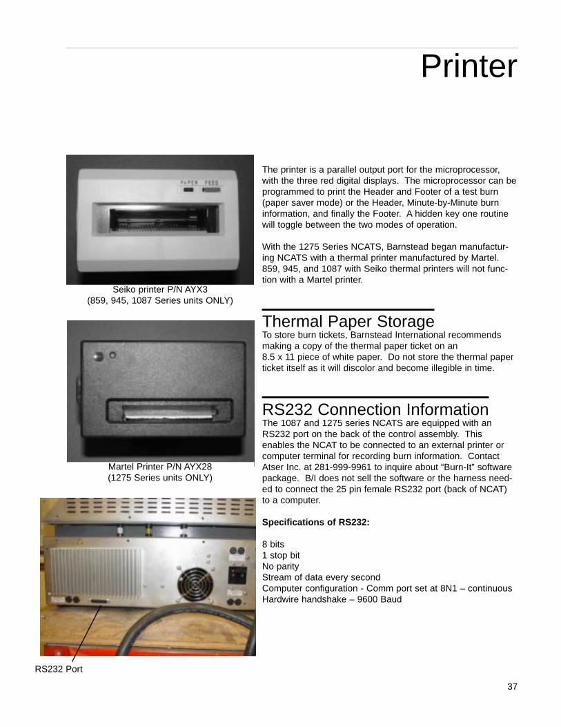
The printer is a parallel output port for the microprocessor,with the three red digital displays. The microprocessor can beprogrammed to print the Header and Footer of a test burn(paper saver mode) or the Header, Minute-by-Minute burninformation, and finally the Footer. A hidden key one routinewill toggle between the two modes of operation.
With the 1275 Series NCATS, Barnstead began manufactur-ing NCATS with a thermal printer manufactured by Martel.859, 945, and 1087 with Seiko thermal printers will not func-tion with a Martel printer.
Thermal Paper StorageTo store burn tickets, Barnstead International recommendsmaking a copy of the thermal paper ticket on an 8.5 x 11 piece of white paper. Do not store the thermal paperticket itself as it will discolor and become illegible in time.
RS232 Connection InformationThe 1087 and 1275 series NCATS are equipped with anRS232 port on the back of the control assembly. Thisenables the NCAT to be connected to an external printer orcomputer terminal for recording burn information. ContactAtser Inc. at 281-999-9961 to inquire about “Burn-It” softwarepackage. B/I does not sell the software or the harness need-ed to connect the 25 pin female RS232 port (back of NCAT)to a computer.
Specifications of RS232:
8 bits1 stop bitNo parityStream of data every secondComputer configuration - Comm port set at 8N1 – continuousHardwire handshake – 9600 Baud
Printer
RS232 Port
Seiko printer P/N AYX3 (859, 945, 1087 Series units ONLY)
Martel Printer P/N AYX28 (1275 Series units ONLY)

38
Printer Change (Production)Seiko to Martel (1087 to 1275)
The Seiko printer used in production of the 859, 945 and 1087 series NCAT is obsolete. The new printer ismanufactured by Martel and will be used in production starting with the 1275 series NCAT in Oct/Nov of 2001.The software is being changed. The reason for the software update is the degree symbol on the front displaywould not print with the Martel.
SOFTWARE UPDATE: REV H software was only used in production for a couple of months. Behind thescene changes were made and we are now using Rev I in production.
Part Number Description
AYX3 Thermal Printer (Seiko)
AYX28 Thermal Printer (Martel)
DL1087X8 Keypad RPO for Seiko printers
DL1275X4 Keypad RPO for Martel Printers
PRINTER
DL1087X8 keypad - 1087 series only(Seiko printer)
DL1275X4 keypad - 1275 series only(Martel printer)
DL859X11A keypad - 859 and 945 series only(Seiko printer)

39
Problem Cause Solution
Printer not printing. The red LED will not illuminate Remove the paper roll fromif paper is removed from the printer. the printer, turn the paper roll The unit uses thermal paper, which over and reinstall in the printer.means characters will only show if Perform a hidden key routinethe paper roll is installed properly. ENTER or WEIGHT key. (Found
in operation manual section of this book). The printer is activated to print the user and balance variables immediately. If the unit prints the variables, the printer itself is most likely not defective and the paper roll is installed properly.
Not printing burn results, but will print Check electrical connections onuser variables when a hidden key is backside of switch on older performed. The 859 and 945 Series models. In the 1087 and 1275 units are equipped with a printer series units this switch is removed insoftware on/off key located below the place of a jumper wire. Wire green power switch on the front control harness part number WH1087X2 panel. If this switch (SWX108) is in the connects to the A/D Converter PC “Off” position or defective, the printer Board(PC859X3A) on the J1 will not print during a burn, yet print terminal. Check for continuity or user variable information during a replace this wire harness, as the hidden key routine. jumper wire is located on the
terminal connector. If the unit still does not print after verifying WH1087X2 is good or replaced, the A/D Converter PC Board may need to be replaced.
If the printer does not print any Replace wire harness and/or printer.information during a burn or when a hidden key ENTER or WEIGHT is performed, yet the displays of the NCATindicate the unit is functioning properly, then the printer is defective or the wire harness ribbon connecting the printer to the Main Logic PC Board (PC859X1A) is defective. (The wire harness ribbon part number is dependent on the series of NCAT.)
PRINTER
Troubleshooting

40
Problem (cont.) Cause (cont.) Solution (cont.)
Print coming out upside down, The Seiko printers are equipped with Power off the NCAT, remove the reading right to left. an internal switch located in the upper printer cover, and slide the
left corner of the printer with the switch to the opposite position. cover removed. The small switch can Replace the cover and perform be slid from the left to the right or vise a hidden key two routine when versa. powering back on. Test printer
again. If still printing upside down or right to left, replace the printer.
Printer ticket indicating If the time and date are not set The time and date of the balance invalid numbers for weight properly in the balance, the software (SETRA or OHAUS) needs to be loss, % loss, calibrated in the NCAT automatically moves the reset. This is not a malfunction asphalt content, temp comp, decimal place to the left on a burn of the printer. (An example burnand bitumen ratio. ticket. be seen in the Error Code section
of this manual.)
PRINTER
Seiko printer switch

HistoryThe following software revisions were used in the NCATfurnaces. All software versions are interchangeable and ifin doubt it is always best to update. The software chip islocated on the Main Logic PC Board (PC859X1) next tothe balance. A sticker on the chip will indicate the revi-sion letter. Hidden Enter Key routine will also prompt theprinter to print the installed revision letter.
Series Version Dates Used859 A – D Used up to 1995945 D – E Used in 19961087 F – G Used in 1997 to 20021275 H Used in 2002 (few months)1275 I Used in production currently
Because the software IC chip is a plug-in style chip (nosoldering necessary to replace) and interchangeablebetween every model/series, production dates (beginningand end) are not important.
*When ordering new software, use part numberAY1087X3. The latest version in production will beshipped. Barnstead will not provide software versionsused in the past. Only the latest revision is production.
Versions A and B were Beta site versions.
Versions C and D were the first two revisions of beta sitesoftware to be used in production. Operation of an NCATwas no different between the software revisions.Changes were all “behind-the-scene” programming toallow the microprocessor to execute commands faster.
Version E: A feature was added to allow operators to pro-gram a positive calibration factor.
Version F: Several new operating features were added. They include:
1. Auto program switching to idle mode. (Unit willstop test automatically when the sample is sta-ble and revert to idle mode, placing an asterisknext to endpoint. This feature frees up opera-tor’s time and increases the number of tests thatcan be run in a days time.)
41
Software
Main Logic Board - Software I.C.

42
2. Maximum test time was extended to 255 min-utes.
3. Maximum load size increased to 4000 grams.
4. Asphalt content expressed in percent loss onburn ticket.
5. Bitumen Ratio calculated and added to print outtest results.
Version G: Several new operating features were added. They include:
1. Programmable time/date function. (This allowsoperators to program the NCAT to begin heatingup automatically at a specific time/date.Operators can arrive to work in the morning tofind the NCAT unit all ready up to burn tempera-ture!) If no date is entered, software will revert toa 24 hour time format. The unit must be in theinactivity mode of operation in order for pro-grammable timer to function properly.
2. Inactivity mode. (If no keys are pressed in 4hours of operation, the display will read “In Ac”in the chamber temp window. This feature willbenefit operators with NCATs in remote loca-tions should the operator not be able to return topower off unit in times of non-use.) The unitmust be in the inactivity mode of operation inorder for programmable timer to function proper-ly.
3. Test interrupt/Power interrupt. (If power to theNCAT is interrupted during a burn and thenrestored, the furnace will continue the test, pre-venting smoke buildup in the lab. The burn ticketwill print “Results Invalid” with “Test Interrupted”.
4. Auto-Shutdown Mode. Software can be toggledby performing a hidden temperature key routineto toggle between Auto and Manual mode ofoperation. In Auto mode, the unit will recognizethe endpoint of a test, stop the blower motorand print the results. The unit will beep onceevery minute to alert operator the test is com-plete. In Manual mode, the unit will recognize
SOFTWARE

the endpoint of a test, place an asterisk next tothe endpoint, but continue to run the test, beep-ing once every 10 seconds to alert the operatorthe test is complete. Operator must press theSTART/STOP key to end test.
5. Stability threshold factor expressed in a percent-age (0.01% - 0.5%)
Version H: Revision H does not contain any operationaldifferences from Revision G. With revision H, “behind-the-scene” programming changes were made to accom-modate the new style of printer being used in productionof the new 1275 series units. The only difference opera-tors will see is on sample tickets where the symbol fordegrees has been removed from the ticket. Version Hwas only used in production for a few months in early2002.
Version I: Revision I is currently being used in production(August 15, 2002) and shipped as replacement softwarefor NCAT units. Revision I contains “behind-the-scenes”changes enabling the software to execute commandsfaster than version H.
SC859X1 Rev. I SoftwareEPROMPower InterruptIf power is lost, then regained during a test, the unit willrestart the blower and continue the test until the endpoint is reached. However, it will read “ResultsInvalid” “Test Interrupted.”
Programmable TimerNew timer allows user to program a specific date andtime for the unit to begin its preheat cycle.
Inactivity ModeAllows user to choose “inactivity mode” which puts unitback to “sleep” as long as no other keys are pressed after 4 hrs. from initial timer wake-up. This mode can be toggled OFF and ON by using the hidden key “Timer” routine. The displayed mode is the active mode.
SOFTWARE
43

44
SOFTWARE
Auto Program switching to idle at test endpoint•Increases the number tests run per day•Frees operator’s time•Asterisk documents endpoint on printout (seeenclosed sample printout on page 45)
Maximum test time extended to 255 minutes and load size to 4,000 grams
•Meets ASTM and AASHTO maximum load sizerequirements•Saves time - no need to split sample size
Asphalt content expressed in percent loss•Meets ASTM and AASHTO test result requirements•Saves time - no need to manually adjust results fromgram loss to percent loss
Bitumen Ratio added to print out test results•Meets international and U.S. requirements•Saves time - no need to perform manual calculations

Installation1. Open hinged front control panel by removing four
screws.
2. The SC859X1 EPROM is mounted in a 16-pinsocket on the edge of the PC859X1A board onthe right side of the furnace. A label on top ofEPROM indicates the part number and revisionlevel.
3. Note orientation of the EPROM notched end torear of the furnace. Gently pry the chip from itssocket until removed. Do not use magnetic toolsin the vicinity of the EPROM.
4. Gently mount the new EPROM into the opensocket. Adjust pins on a flat surface if not match-ing socket.
5. Refasten control panel.
6. Turn power switch on. Review and adjust defaultvalues.
7. Your unit is now ready for operation.
45
SOFTWARE
SDL
U4
5DIG+
J15
C3
5DIG
C15
C16
C14
+
+
J32R2
R37
R38
J4
-
U8
INT
ER
CO
M C22
J2 LEDS
R22
+
R21
R20
R19C27C26
SSR
J3
R14
CRY1
RESET
JMP1
J31 C28
C30 C29
5DISP J9 DISPLAYU12
C8
U5
C9
R6
+
R17
R10
C21
C12
C6 C20
C13
U6
+
+
R3
U7
PC859X1A
C1
C18
C17
U9R15
+R8
R40R5
U3C2
R39
R24
R1
R23
J1
+
C5
U10
R25
C31 SCALE
J5 J7
J27C4 +
C23
12DIG R4
C11
C10
C7U2
+
Q1
Q2Q4
C63C64
C19 U1+
+
5PT
R
J23
+
-
J28
J29Q3
+
U13
J30
J6
Printed Circuit Board Assembly
SC859X1EPROM
Sample printout

46
SOFTWARE
R8
C18
R17
5DIG
+
C14
J15
+
U5
C8
+
C17
PC
859X
1A
U2
C7
C6 C
13
J31
U8
+U6
R6
C31
C12C21
C29
C30
C28 JMP
1
RE
SE
T
CR
Y1
R14
J3SS
R
C26
C27
R19
R20
R21
+
R22
J2 L
ED
S
C22
INTERCOM
-
J4
R38R
37
R2
J32
+
C16
C15
C3
+
5DIG
U4
C4
SC
ALE
U7
R3
+
C20
R10
C9
U12
J7J5
R25
+
J1
R23R
1
R24
R39 C
2U
3
R5
R15
U9
C1
J9 D
ISP
LAY
5DIS
P
C63 C
19
Q4
J6J30
U13 +
+
U1
C64
Q2
Q1
+C
10
C11
R4
12D
IG
C23
+
J27
U10
C5
R40
SD
L
+
Q3
J29
J28
- + J23
5PTRLoca
tion
of E
PR
OM

47
Ordering Information
Revision “I” Software Kit AY1087X3
1 ea. SC859X1 EPROM Labeled Rev. I Software1 ea. Installation Instructions1 ea. Set of Operation Manual Amendments
SOFTWARE

AmendmentTIMER PROGRAMMING & HIDDEN KEY
PROCEDURES FOR REVISION “I” SOFTWARE
DefinitionHidden Keys provide multiple use of the keypad. HiddenKey Procedures typically are used to access infrequentlychanged user variables and infrequently used diagnosticprocedures. The access, procedure and exit are detailedunder each key procedure. The furnace must be in theidle (non-programmable) mode to access the HiddenKeys.
Amendment #1 applies to Operation Manuals, PartNumbers LT859X1, LT945X1, LT945X3 and LT945X4 forNCAT Asphalt Content Tester.
Programmable TimerHeating the furnace to operational levels may require twoor more hours of preheating but leaving the furnace onconstantly may not be efficient, consuming both electricityand heating elements. To optimize your working hours,we have designed an automatic preheat timer into yourasphalt testing furnace. This feature allows you to beginwork immediately each day, but only run your furnace asmuch as necessary to complete your days work.
Programming the TimerThe following directions will explain how to program the“wake-up” date and time into your asphalt furnace. Thiswill determine exactly when the furnace will begin pre-heating to your setpoint temperate. We recommend thatyou set the time for at least 2-1/2 hours before you wantto begin work.
1. Press the timer button on the key pad. Theheating element will shut down at this time.The wake-up time will be displayed in the“Elapsed Time” display and the “wake-up” datewill be displayed in the “Percent Loss” display.
2. Enter the “wake-up” date by inputting the
48
Procedures
NoteIf you don’t want to enter a “wake-up”date you can bypass this feature bysimply pressing “ENTER” after youhave presses the timer button in step1. Bypassing the date automaticallyconverts the timer from a programma-ble 364 day timer to a 24-hour timer.This means that when the pro-grammed “Time” is reached, the unitwill begin heating, ignoring the “wake-up” date. The date needs to be set at0.00 for this to happen.

month and then the day. Example: May 16thwould be entered 5/16. Then press ENTER.The “wake-up” date is now set.
3. You may now proceed to enter the “wake-up”time.
If at any time you wish to disable the timer, press theSTART/STOP button.
Interrupting the Timer Mode(Same as before.)
Inactivity ModeBy using the hidden key feature with the “Timer” key, youcan select the Inactivity Mode. This mode allows the fur-nace to “wake-up” at the programmed time and date, butif the user does not press any keys for a period of 4hours, the unit will shut down and “In Ac” will be displayedin the chamber temp display. The unit will remain shutdown until the user presses the START/STOP key.Pressing the START/STOP key will set the unit into itsnormal idle mode.
The Inactivity Mode is a valuable feature should the unitbe placed in a remote location, and the operator is notable to return due to unexpected circumstances such asinclement weather. The unit will remain shut down untilthe user presses the START/STOP key.
Test Interrupt/ Power InterruptIf the power to the furnace is interrupted during an ignitiontest, and then restored—the furnace will continue the testbut will print the following information on the ticket:
[Results Invalid]Test Interrupted
Time: XX:XX:XX
The elapsed time will restart at 1 and continue to countup. The software will continue to monitor the weight lossand recognize the endpoint to end the test.
This feature will prevent smoke from entering the labshould a power interrupt occur. Once power has been
49
PROCEDURES
NoteThe timer format is European orMilitary time so to enter a wake-uptime of 5:00 a.m. you would input 500and then press ENTER. A wake-uptime of 5:00 p.m. would be inputted as“17:00” then press ENTER. The startup time and date are now entered.

50
restored the blower will start up again to maintain air flowthrough the chamber. This will also prevent the user fromprematurely opening the door.
The power interrupt feature also applies to the program-mable timer. Should the power go off during the nightwhile the unit is asleep and then come back on prior tothe programmed “wake-up” time, the software will recog-nize the present time and “wake-up” at the correct pro-grammed time.
Auto Shut-Down ModeSoftware can be toggled between Auto Mode and ManualMode by performing a Hidden Temp Key Routine. In theAuto Mode, the unit will recognize the endpoint, stop theblower, print the results, and then BEEP once every 60seconds until the operator presses the START/STOP key.This will unlock the door and disable the beep.
In the Manual Mode the unit will recognize the endpointand place an asterisk by the endpoint. It will continue torun the test and beep until the operator presses theSTART/STOP button.
O Key-Diagnostics:
Access: Depress the Power Switch to “ON whilesimultaneously depressing the “O” key.
Procedure: Enter the diagnostic procedure for factorytesting.
The furnace must be at room temperatureand unloaded. Run time is approximatelytwo hours. Upon accessing, the uservariables will default to factory set vari-ables in order to match the variablesused in the factory test. You will need toprompt the initial test segments bydepressing the START-STOP key tomove to the next segment. Test segmentsrequiring heat-up times automatically pro-ceed to the next segment without prompt-ing.
PROCEDURES

Exit: Depress Power Switch to “OFF” and then“ON” to return to normal operation.
1 Key-Print Out Paper Saver:
Access: Depress Power Switch to “ON” whiledepressing the 1 key simultaneously.
Procedure: Chamber temperature display will displayPRN and the Percent Loss display willtoggle “ON” or “OFF” as the access pro-cedure is repeated. The new mode will bedisplayed for three seconds and then thefurnace will return to normal operation.
Exit: Automatic
2 Key-Default:
Access: Depress the 2 key while simultaneouslydepressing Power Switch to “ON”.
Procedure: DEF will be displayed for three secondsto indicate variables have been reset tofactory values. The furnace will return tonormal operation. Defaulting to factoryvalues is a useful diagnostic tool as acomparison of current values vs. factoryvalues can be made within minutes.Values can be printed by depressingENTER while simultaneously depressingthe Power Switch to the “ON” position.
Exit: Automatic
3 Key-Chamber Calibration Procedure
Equipment 1 ea. Digital Pyrometer withNeeded: Penetration Probe, Sensor NIST
Traceable. (Recommend ThermolynePM20700 with TC405X4 PenetrationProbe).
51
PROCEDURES

52
Setup: Calibration consists of inserting a sensorpenetrating through the covered stainlesssteel tube located adjacently to the con-trol thermocouple. Entry is at the centerrear of furnace chamber. The penetratingprobe is needed to penetrate through thesoft insulation. Probe insertion is at thesame depth of the chamber control ther-mocouple. Cover probe entry tube afterthe calibration procedure has been com-pleted. Do not place pyrometer on top ofhot furnace. After inserting the test ther-mocouple penetration probe, set furnaceat 538°C or standard method specifiedtemperature. Allow furnace chamber tostabilize at set point in the idle mode. Themaximum offset allowed before hardwarecalibration is required is +50°C.
Access: Depress 3 key while simultaneouslydepressing power switch to “ON”.
Procedure: CHBR CAL will be displayed in thePercent Loss and Elapsed Time windowsrespectively. The Chamber Temperaturewindow will display the actual chambertemperature which should be at or nearset point temperature. Allow the furnaceto stabilize at set point.
Enter the temperature displayed in °C bythe digital pyrometer by using the keypad.Press “ENTER”. The new offset value willbe used and the entered temperature willbe displayed. The entered temperature isthe temporary set point.
The original set point will return upon exit-ing. The software has calculated andsaved the new offset value, which willapply to all set points throughout theoperating range.
Exit: Depress Power Switch to “OFF” and then“ON” to return furnace to normal use.Remove sensor probe and cover entrytube.
PROCEDURES
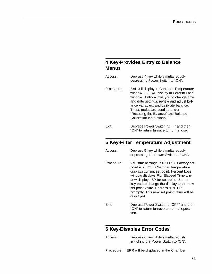
4 Key-Provides Entry to BalanceMenus
Access: Depress 4 key while simultaneouslydepressing Power Switch to “ON”.
Procedure: BAL will display in Chamber Temperaturewindow. CAL will display in Percent Losswindow. Entry allows you to change timeand date settings, review and adjust bal-ance variables, and calibrate balance.These topics are detailed under“Resetting the Balance” and BalanceCalibration instructions.
Exit: Depress Power Switch “OFF” and then“ON” to return furnace to normal use.
5 Key-Filter Temperature Adjustment
Access: Depress 5 key while simultaneouslydepressing the Power Switch to “ON”.
Procedure: Adjustment range is 0-900°C. Factory setpoint is 750°C. Chamber Temperaturedisplays current set point. Percent Losswindow displays FIL. Elapsed Time win-dow displays SP for set point. Use thekey pad to change the display to the newset point value. Depress “ENTER”promptly. This new set point value will bedisplayed.
Exit: Depress Power Switch to “OFF” and then“ON” to return furnace to normal opera-tion.
6 Key-Disables Error Codes
Access: Depress 6 key while simultaneouslyswitching the Power Switch to “ON”.
Procedure: ERR will be displayed in the Chamber
53
PROCEDURES

54
Temperature window. “OFF” will be dis-played in the Percent Loss window. Thefurnace will automatically return to normaloperation within five seconds with theerror codes deactivated.
Error codes are defeated to perform diag-nostic procedures as to temporarilyensure continued furnace operation in theevent of an error code.
Exit: Depress the Power Switch to “OFF” andthen “ON” to return the furnace to normaloperation with activated error codes.
7 Key-Displays Actual Filter andChamber Temperatures:
Access: Depress the 7 key while simultaneouslydepressing the Power Switch to “ON”.
Procedure: Chamber temperature will display actualchamber temperature. The Percent Lossdisplays actual filter temperature. Use fordiagnostic purposes only.
Exit: Depress the Power Switch to “OFF” andthen “ON” to return the furnace to normaloperation.
8 Key-Serial Port Output Adjustment
Access: Depress the 8 Key while simultaneouslydepressing the Power Switch to “ON”.
Procedure: SPC or SPn will display in the ChamberTemperature window for three seconds.SPC prints the serial output continuously.SPn prints the serial output only when thefurnace is in the program mode.Accessing toggles the mode betweenSPC and SPn. The displayed mode is theactive mode. Default is the SPC mode.
PROCEDURES

Exit: Automatically returns to normal operationwithin three seconds.
9 Key-Disables Beep
Access: Depress the 9 Key while simultaneouslydepressing the Power Switch to “ON”.
Procedure: The Chamber Temperature will displayBEEP. The Percent Loss window will dis-play “ON” or “OFF”. The mode conditionwill display for three seconds. Accessingtoggles the mode between “ON” and“OFF”. The displayed mode is the activemode. The default mode is BEEP “ON”.
The option to inactivate the beeper isuseful for raw aggregate calibration whenminute losses may cause the endpointbeeps to activate prematurely before theprocedure has been completed. The keypress beep is not disabled in the BEEP“OFF” mode.
Weight Key-Prints Out Balance Variables
Access: Depress the weight key while simultane-ously depressing the Power Switch to“ON”.
Procedure: The Percent Loss Window will displaySCAL. The Elapsed Time window will dis-play L1S. The printout will generate auto-matically upon entering the printoutmode. See Hidden Weight Key printout atleft for balance variables. You can com-pare current printout with the example toensure correct variables are entered.
Exit: The furnace will automatically return tonormal operation after the printout is gen-erated.
55
PROCEDURES
Setra Balance Printout
Ohaus Balance Printout

Enter Key-Prints Out User Variables
Access: Depress the ENTER Key while simultane-ously depressing the Power Switch to“ON”.
Procedure: PRN will display in the Percent Loss win-dow. User will display in the ElapsedTime window. The printout will generateautomatically upon activating hidden keysequence.
Exit: The furnace will automatically return tonormal operation after the printout is gen-erated.
Calibration Factor Key-Adjust orCheck Test Stability Threshold at TestEndpoint
Access: Depress the Calibration Factor Key whilesimultaneously depressing the PowerSwitch to “ON”.
Procedure: The stability threshold setting will be dis-played in the Percent Loss window. TheElapsed Time window will display FLN.The value options are 0.01, 0.02, 0.03,0.04%. Enter the new value via keypad.Observe the Percent Loss window as thenew value is entered. The new valuemust be entered and the ENTRY Keymust be depressed within five seconds.
ASTM Draft 6 specifies test endpointcompletion when the measured massloss does not exceed 0.01% over threeconsecutive one-minute periods. AASH-TO specifies endpoint completion whenthe mass loss does not exceed 0.02%over two consecutive one-minute periods.The test stability threshold value definesthe endpoint. This value must match thestandard specification you are applying.The test stability value is printed on the
56
PROCEDURES

User Variable Printout. See Hidden KeyENTER. An example of the printout isdepicted on page 58.
Exit: Depress Power Switch to “OFF” and then“ON” to return furnace to normal opera-tion.
Temp Key - Toggles from AutoProgram Switching to Idle or ManualProgram Switching to Idle at End-point
Access: Depress TEMP key while simultaneouslydepressing the Power Switch to “ON”.
Procedure: AU appears in the Chamber Temp display.The Percent Loss displays either “ON” or“OFF”. If “OFF” is displayed, repeatingaccess changes the display to AU “ON”.You are now in the Auto ProgramSwitching to Idle mode. Repeat Accessagain to return to the Manual ProgramSwitching to Idle mode.
Auto Program Switching to Idle canincrease the number of tests run per day.The operator’s monitoring time is elimi-nated as the test results automaticallyprint out at endpoint. The ManualProgram Switching to endpoint is stillavailable in the event continuous runningis required after endpoint.
Exit: AU “ON” or “OFF” is displayed forapproximately five seconds. The furnaceautomatically returns to idle.
Timer Key - Disables Inactivity CheckAccess: Depress the timer key while simultane-
ously depressing the power switch to“ON.”
Procedure: The Chamber Temp will display InAc. The Percent Loss window
57
PROCEDURES

58
will display “ON” or “OFF.” The ModeCondition will display for three seconds.Accessing toggles the mode between“ON” and “OFF.” The displayed mode isthe active mode.
Active Keys
These keys activate a function when depressed. The fur-nace must be in the idle(non-programmable) mode.
0 Key-Tares the Balance
Access: Depress “0” key. The balance will auto-matically tare to “0” grams in the balancedisplay.
Procedure: This mode is useful to perform the “lifttest”, as the balance must be tared beforeconducting test. See Glossary.
The weight of the loaded basket assem-bly can be rechecked if the balance istared prior to loading.
Exit: Automatic
Enter Key-Duplicates Header TestResults
Access: Depress the ENTER key.
Procedure: The header and footer test results willprint out for last test if no other key func-tions have been performed since printingof the last test results. The power switchmust not be switched “OFF” and “ON”after the original test report is generated.
This feature provides as many headercopies of the last test results as neededby the operator.
Exit: Automatic upon completion of printout.
PROCEDURES

Bitumen RatioThe Bitumen Ratio has been added to the Rev. “I” soft-ware. This test result is used in the United States andEurope. The Bitumen Ratio equation is detailed as fol-lows:
Bitumen Ratio = (Weight Loss/SampleWeight after ignition) x100% minus temperaturecompensation, minus cor-rection factor.
The Bitumen Ratio test results are printed in the headerabove the calibrated asphalt content for each test.
NOTE: When developing aggregate calibration factors,the desired output must be determined. If calibratedasphalt content value is used to develop the aggregatecalibration factor, the Bitumen Ratio value should beignored. The opposite is true if Bitumen Ratio value isused to develop aggregate calibration factor.
59
Output

60
Balance Stability: The small “S” will flash on and offat the left side of the balance dis-play. When the “S” is shown, thebalance is stable. It is normal forthe “S” to flash early in the igni-tion procedure, as rapid sampleweight loss occurs early in the fir-ing procedure and diminishes asignition nears completion. The “S”will not illuminate if the furnace issubject to vibration from otherequipment in the lab. The stabileindicator on the control panel isnot related to the “S” balance sta-bility indicator.
Calibration Factor: Addresses the aggregate weightloss or gain which occurs duringthe ignition process. This loss orgain is not related to asphalt con-tent loss and is added or sub-tracted from the asphalt content.Standard methods specify theprocedure for determination. Thiscalibration factor is entered bythe operator.
Default: Resets your current values to thefactory values. See hidden keys 0and 2.
Default Values: These are factory values appliedto each unit for testing duringproduction. A printout of thesevalues are supplied with eachunit. Default values can be com-pared to your current values toassess correct entry of eachvalue.
Error Codes: Error codes are displayed to noti-fy the operator of an out-of-speci-fication condition or modification.Error codes range from E001 toE005 and E007 to E012.Explanations are detailed in theOperation Manual.
Glossary
HMA: Hot Mix Asphalt.
Idle Mode: This mode is entered on startupafter initialization. Revision “I”software automatically transfersfrom the program mode to theidle mode upon completion of thetest. The furnace will idle at setpoint temperature in preparationfor the next test. The blower is“OFF” in the idle mode.
Initialization: This procedure sets up and con-figures the furnace for operatoruse when the Power Switch isdepressed to “ON”. Initializationtime is approximately 5-15 sec-onds.
Lift Test: This test measures the blowerefficiency when the furnace is inan unloaded condition and is atroom temperature. The operatoris required to tare the balance,depress the start-stop key, andobserve the balance display.Normal lift measurements areminus 3.5-10 grams.
NCAT: National Center for AsphaltTechnology.
Offset Value: This value is the temperature dif-ference between the stabilizedchamber displayed temperaturevalue and the chamber tempera-ture verification value determinedby the External DigitalThermometer.
Program Mode: This mode is entered by depress-ing the start-stop key. The pro-gram mode is used to determineasphalt content of a HMA sample,calibration of the HMA sample, orraw aggregate.
61
GLOSSARY

Temperature This factor compensates forCompensation the loaded basket assemblyFactor: weight reduction experienced
when placed in the ignition furnace chamber at temperature.The Temperature CompensationFactor is automatically calculatedby the furnace software. This fac-tor must be employed in the igni-tion process to achieve accept-able precision and accuracyspecified by standard methods.This factor is subtracted from the asphalt content.
Test Endpoint: This is the point at which theHMA sample weight loss doesnot exceed the “Test StabilityThreshold Setting” for three con-secutive one-minute periods.Furnaces containing Rev. I soft-ware will end the test, asteriskthe endpoint reading on the print-out, and switch from the programmode to the idle mode at end-point if the Auto ProgramSwitching to idle is employed.
Test Stability This adjustable variableThreshold: determines the endpoint of the
HMA sample mass loss. The testis complete when the measuredmass loss does not exceed thestability threshold setting for threeconsecutive one minute periods.The stabile indicator on the frontcontrol panel indicates the teststability threshold (endpoint) hasbeen attained.
62
GLOSSARY

63
Red Display (Furnace)NOTE: Furnace ERROR Codes – RED display window. All error codes (unless explicitly noted) will cause thetest procedure to stop. Microprocessor checks for error codes occur every second. It goes through the errorsin order of importance starting at #1. If there are multiple errors occurring at the same time, the first errorcode will display on the unit.
Errors
SolutionThermocouple resistance is </= 1 ohm. If it isopen, replace it. If it is good check the connec-tions at rear of furnace. Thermocouple leadsare red (-) and yellow (+).
Follow above procedure for filter thermocouple.
Key routine #7 – will display the actual tempera-ture. If the temperature readout is erratic,replace the analog board (bad optocoupler).
If the readout is correct and the readout is675°C, see if they recently changed any parts inthe unit – especially the thermocouple. It couldbe a thermocouple with the leads labeled wrong(red wire = magnetic, yellow wire = non-magnet-ic) or thermocouple connected to the wrong con-nector. (i.e. Chamber thermocouple wiring con-nected to the filter thermocouple wiring.) Samewith a SSR that was replaced, verify the wiringto make sure they were not switched.
Check for shorted heating element.
Check for shorted SSR.
Follow above procedure.
Is the unit brand new? Plunger is misalignedand should move freely up and down. (Plungeris located on the lower right hand corner of theunit.) Realign the position of the door hinge pinsin the door hinge brackets. Check for a bent link-age bracket to adjust or a dent in the side of theunit. Straighten case if necessary.
CauseChamber Thermocouple is open.Tip maybe cracked at the weld and the crackmay open with thermal expansion.
Filter thermocouple open.
Chamber temperature limit of 675°C isexceeded. This will only come up whennot running a cycle. This error is dis-abled while in the test program mode.
Filter temperature limit of 975°C isexceeded.
Door interlock not functioning.
Error CodeE001
E002
E003
E004
E005

64
ERRORS
Solution (cont.)
Solenoid valve is bad and not engaging theplunger. Turn unit on and start cycle to listen forthe solenoid valve to active. Watch for move-ment in the plunger. To remove the door solenoid:
1. Disconnect the power to the unit anddrop down the front control panel.
2. Remove the two wires on solenoidvalve and two screws on the outside ofthe case.
Microswitch on right side of the unit has failed.This switch looks for the plunger to engage.12VDC pulse engages the solenoid valve.
Door switch on left side of unit - make sure it isconnected.
Main Logic Board has failed (Moss FET onboard has failed.)
Turn the unit off and power back up. If E003comes up then proceed with E003 informationabove.
If E003 does not come up then replace the LogicPC Board or the Main PC Board.
Reset the time and the date.
Recalibrate the balance.
Check the balance connection.
Replace balance and/or cable WH859X3A. If thebalance needs to be replaced, see BALANCEsection of this manual.
No display on balance display – OHAUS bal-ance - check the fuse on the balance.
Cause (cont.)
Analog to Digital Convert is not func-tioning properly. A component failureor faulty cable connection may causethis. This should only occur during atest.
The DTR signal from the balance isindicating the balance is either notready or not connected.
Error Code (cont.)
E005 (cont.)
E007
E008

65
ERRORS
Cause (cont.)
Set point is out of range. This is atemporary error to alert you that youhave crossed the allowable boundaryfor the function you are setting.
Chamber thermocouple leadsreversed. Thermocouple is a type “K”.Polarity is coded as red (-) and yellow(+).
Filter thermocouple leads reversed.
Balance not communicating; weight,time and date not received.
Error Code (cont.)
E009
E010
E011
E012
Solution (cont.)
The furnace will beep for 3 seconds while dis-playing this error and then return to normaloperation. The setpoint will revert to its previ-ous valve. Chamber temperature is to be lessthan 674°C; Filter temperature is to be lessthan 900°C.
If the thermocouple was just replaced, thenreverse the leads.
Check to see if E003 comes up while the unitis NOT running a program.
If this error occurred during operation, performhidden key routine #7 to verify the tempera-ture. If the displayed temperature is erratic,replace the analog board.
See above to proceed.
Follow steps in E008. If the balance needs tobe replaced, see BALANCE section of thismanual.

66
ERRORS
Green display (BALANCE)NOTE: Balance error codes will be displayed in the green balance display. With most error codes below,power unit down and power back up to see if the error goes away. If it continues try to recalibrate, however, ifthe error will not clear, the balance will need to be replaced. See the BALANCE section of this manual. Twotypes of balances have been used in the NCAT furnace.
OHAUS Balance(Most common error codes. See Ohaus manual for the full list of error codes)
Error Code
3.0
4.4
8.0
EEEE
Cause
Calibration Error - Incorrect or no calibra-tion weight used for calibration.
RS232 buffer is full. There is a bad con-nection in balance.
Hardware error causing an internalweight signal which is too low.
Displayed momentarily.
Solution
Recalibrate with correct weights. Make sure alldebris is off the top of the balance and the postssupporting the aluminum calibration plate arecentered. Only the aluminum calibration plateshould be used during the calibration procedure.If this error is only displayed when calibratingthe unit, the software is bad and the unit needsto replaced.
Double check all connections.
Check if the platform or platform support is off.If not, balance must be serviced.
NCAT is getting power disconnect for a briefsecond and resetting itself.
SETRA Balance (Error codes, unless specifically stated, refer to note at the top of the page.)
Error Code
HHHHH
LLLLLL
NOCAL
Cause
Exceeds maximum specified load (5000grams).
Load does not meet minimum specifiedload requirements.
Unable to do span calibration (load notwithin 1% of cal weight, or weight unsta-ble)
Solution
Reduce load to specified range.
Increase load to specified range. Make sure theceramic posts are centered and the plate is ontop of them.
Replace scale.

67
ERRORS
Error Code (cont.)
PPPPPP
ProtEc
REPlug
OFLO
S Err
In Err
UnABLE
Cause (cont.)
Strain on the DC power supply.
Calibration protect switch not in thePROTECT position during opera-tion.
System not calibrated.
Internal arithmetic overflow.
Processor stack overflow.
Memory indexing error.
Unable to process command (usu-ally due to being in impropermode).
Solution (cont.)
Disconnect printer to see if the error goes away.If it does, replace printer.
Replace scale.
Replace scale.
Replace scale.
Replace scale.
Replace scale.
Replace scale.

68
ERRORS
NCAT Troubleshooting with No Error Codes Displayed
Error
Keypad failure
Blower motor failure
Low lift-test reading(Complaint)
Symptom
The NCAT unit may beep or chirpin a non-rhythmic fashion.
The red displays will indicate char-acters (numbers and/or letters)that do not coincide with whatshould be displayed or what is nor-mal.
NCAT performs a hidden key rou-tine when initially powered on, yetend user did not initiate a hiddenkey routine.
Results from lift test will not meetspecifications.
Full potential line voltage is appliedto the blower motor in test modebut blower will not run.
Motor may run, but makes abnor-mal noises.
A low lift-test reading is when per-formed by operators to signify rou-tine maintenance needs to be per-formed. Lift-test readings shouldrange from -3.0 to -8.2. (SeeMaintenance Section for proper lifttest procedure.)
Action
Test keypad (See Equipment Test Proceduresection.)
Replace keypad (Serial number of NCAT need-ed to identify correct replacement part numberof keypad.)
Test blower motor by monitoring feed voltage.
Voltage will measure full potential line voltageon 945 series and 1087 series NCATs. 859series units will measure full potential line volt-age (if upgraded) or 120Vac.
Oil blower motor (See Maintenance Section.)
Replace blower motor. (Serial number of NCATneeded to identify correct replacement partnumber of blower motor.)
Follow the cleaning procedure steps. (SeeMaintenance Section)
Test/replace the blower motor. (Serial number ofNCAT needed to identify correct replacementpart number of blower motor.)
The insulation in the upper plenum may need tobe replaced. If the blanket insulation is not tight-ly tucked against the top sides of the NCAT, airwill not be forced through the five air baffleholes. Instead the air escapes around the outeredges resulting in a low lift test.

69
ERRORS
Error (cont.)
Smoke coming fromcontrol section dur-ing a burn
Symptom (cont.)
In addition to control section emit-ting smoke, a complaint of longertest/run times, a fowl odor, blackcolored substance running downthe back balance supportcolumn(s), sample not burning outcompletely and inaccurate testresults.
Action (cont.)
Perform a lift test with and without the exhausttubing attached. (See Lift Test Section.) Ifresults are out of specification, follow the clean-ing procedure steps. (See MaintenanceSection)
Check the door insulation for black streaks run-ning from the edge of the insulation towards thecenter. This indicates the door is too loose andin need of tightening. (See MaintenanceSection)
Monitor the axial cooling fan located in the backof the control section. The cooling fan shouldbe sucking ambient air into the control sectionfrom the room. It should not be pulling air out ofthe NCAT control section. Axial fan may needto be remounted properly or replaced.
Test the afterburner element in the 1087 seriesunits or the top element in the 945 and 859series units. (See element equipment test pro-cedure.) If this element is not heating properlythe unit will not be able to breakdownfumes/soot generated during the run mode. Thetop plenum of the unit will clog in a very shorttime and soot will build up rapidly as a result. Itthis element tests okay, then test the solid staterelay. (See SSR equipment test procedure.)
In 1087 Series units, there is a 1" diameter holecut in the back piece of insulation. Locate thehole in the lower left side of the back of thechamber and use a sturdy piece of wire toloosen any soot build up. The hole acts as a chimney and may clog up with soot.Replacement of this piece of insulation may benecessary.
Ventilation system may be inadequate. (SeeMaintenance Section; Air Pressure.)

70
ERRORS
Error (cont.)
Tests never end(Complaint)
Burn ticket indicatesthe load actuallygains weight(Complaint)
Unit will not heat upbut displays appearnormal (Complaint)
Symptom (cont.)
If the sample does not lose morethan 15 grams at the end of the15th minute, the software is pro-grammed not to detect an endpointand the test will run until stoppedby the end user. (Written into software due to early aggregatecalibration procedures.)
Support posts may be touching orrubbing as may the ceramic plateor basket in the chamber.
Evaluate basket. As baskets age,they may start to warp, especiallywhen introduced in a hot chamber.
If the area ambient temperature isbelow 50°F, the main microproces-sor will not recognize the milli-voltsignal generated by the thermocou-ples.
Action (cont.)
Perform a test in which minute by minute testresults are printed out. Examine the burn ticket& note the weight loss at the 15th minute. If notgreater than 15 grams, unit is performing as itshould. (See Sample Ticket Section.)
Perform a hidden key 2 routine and attempt toburn a 1500 gram sample. Initial sample mayhave been too large.
Recalibrate balance or replace balance. (SeeBalance Section.)
Inaccurate temperature indication on display.Verify chamber temperature with an externalN.I.S.T. Pyrometer and probe. Calibrate tem-perature.
Ensure samples are being leveled off in bas-kets. DO NOT MOUND SAMPLES, as theinternal portions of the sample may not burn outCompletely due to the lack of oxygen to burn.
Ensure all are centered and try running anothersample. (See Sample Ticket Section.)
Warping may cause the basket to rub againstthe chamber. Basket(s) may need to bereplaced.
Recalibrate balance. (See Balance Section.)
Replace the balance.
Attempt to warm the tip of the chamber thermo-couple by holding it in the flame of a match for15 seconds. Close chamber door and see if unitstarts to heat.
Use a portable space heater to warm the elec-tronics of the unit. Allow 15 to 30 minutes forNCAT to warm.

71
ERRORS
Error (cont.) Symptom (cont.)
Test results inaccurate from sampleto sample of the same source
Action (cont.)
Ensure samples are the same size (weight.)
Methodology errors in sample splitting.
Recalibrate balance or replace balance.
Verify chamber temperature accuracy; recali-brate if necessary.
REMINDER: Barnstead International has premixed samples of asphalt that can be sent to customers thathave problems burning obtaining repeatable results and poor accuracy. Our samples are hand mixed at5.0%. Our samples should be burned with a calibration factor of 0.0 at 538°C (chamber temp). Results willshow 4.9% to 5.1% ac. in a fully functional NCAT.

72
AggregatesIssues that can affect the accuracy and repeatability ofthe results not related to the NCAT:
1. Sample size consistency2. Splitting errors3. Moisture in mix4. Type of material
Limestone, granite, and sandstone are the three mostcommon base aggregates used. Granite is the hardest ofthese three. Sandstone is the softest with limestonebeing the medium. It is generally seen that harder aggre-gates burn more accurate than softer aggregates.
Dolomite is a base aggregate used in some parts of theUnited States (Indiana, Ohio). Dolomite based samplesare difficult to burn with repeated accuracy in the NCAT.Off gases produced during burns cause mini like explo-sions in the chamber of the NCAT during a burn (like pop-corn being popped). Barnstead has done extensive test-ing with Dolomite based samples. Copies of results areavailable upon request.
Hydrated Lime is sometimes added to to HMA to improvebinder adhesion to certain aggregates. Hydrated lime willmigrate to the aggregate during the burn, trapping someof the asphalt into the aggregate. In severe situations,the aggregate gradation may appear to actually gainweight after a burn is complete.
Negative Air PressureAir temperature and altitude have an impact on air pres-sure, specifically the exhaust system on the NCAT.Negative air pressure refers to an “area” that has lessatmospheric pressure exertion versus another. The“area” referred to is the room/building the NCAT is beinginstalled versus the atmosphere (outside). If the atmos-pheric air pressure is greater than the room/building airpressure, you have a negative air pressure condition.The atmospheric pressure will attempt to offset the roomor building pressure and equalize. The ventilation system
ERRORS

of the NCAT provides a direct path for atmospheric airpressure to enter the room/building when exhausteddirectly through an outside wall or the roof. The NCATdoes have a 60CFM rated blower motor to aid the ventila-tion process, but in some situations, the pressure differ-ence is too great and the blower motor can not prevent orstop the negative air pressure from occurring. Smokegenerated for the NCAT will fill the room and/or the lift testwill be low. This is a design issue in the buildings ventila-tion system, not the fault of the NCAT. There are a cou-ple of options if the NCAT is to be installed at this loca-tion.
1. Open any doors or windows in the room. Thismay be enough to offset the pressure differ-ences, allowing the NCAT to be operated prop-erly.
2. Install a second blower motor in-line with theventilation tubing from the NCAT. The secondblower motor must be installed no closer than10 feet from the unit. Barnstead/Thermolynedoes not offer a selection of blower motors forthis purpose and a motor would have to be pur-chased locally.
3. Checking the buildings ventilation system. Thisis would require consulting a HVAC technician.
73
ERRORS

74
Displayed Letters/Numbers“IN Ac” = Inactivity Mode. This mode is part of the timer,which allows the unit to automatically turn on and heat toset point temperatures. “IN Ac” will be displayed if theuser does not press any keys for a period of four hours ifthe timer is set. Customer must press the start/stop keyto return to the idle mode. Hidden Key TIME will alsocause “IN Ac” to be displayed.
“PRN” = Printer. “PRN” will be displayed in the ChamberTemp window. On or Off will be displayed in the percentloss window to indicate if the printer is to print the headerand footer of tests or minute by minute test results.Hidden Key 1 toggles the “PRN” On or Off.Hidden Key ENTER will also cause “PRN” to be dis-played.
“DEF” = Default. “DEF” is displayed for 3 seconds in theChamber Temp window to indicate the variables havebeen set back to factory default. Variables affected arechamber temperature (538C), filter temperature (750C),and stability threshold (.02%). Hidden Key 2 reset vari-ables back to factory default.
“CHBR CAL” = Chamber Calibration. “CHBR CAL” will bedisplayed in the Percent Loss window and Elapsed Timewindow. Hidden Key 3 will cause “CHBR CAL” to be dis-played.
“BAL” = Balance. “BAL” will be displayed in the ChamberTemp window. Hidden Key 4 will cause “BAL” to be dis-played.
“FIL” = Filter. “FIL” will be displayed in the Elapsed Timewindow. Hidden Key 5 will cause “FIL” to be displayed.
“ERR” = Error. “ERR” will be displayed in the ChamberTemp window. Hidden Key 6 will cause “ERR” to be dis-played.
“SPC” or “SPn” = Serial Port Output. “SPC” or “SPn” willbe displayed in the Chamber Temp window for 3 seconds.Hidden Key 8 will cause “SPC” or “SPn” to be displayed.
“BEEP” = Beep. “BEEP” will be displayed in theChamber Temp window. Hidden Key 9 will cause “BEEP”to be displayed.
ERRORS

“SCAL” = Scale. “SCAL” will be displayed in theChamber Temp window. Hidden Key WEIGHT will cause“SCAL” to be displayed.
“FLN” = Stability Threshold. “FLN” will be displayed in theElapsed Time window. Hidden Key CALIBRATION FAC-TOR will cause “FLN” to be displayed.
“AU” = Auto Program. “AU” will be displayed in theChamber Temp window. Hidden Key TEMP will cause“AU” to be displayed.
75
ERRORS
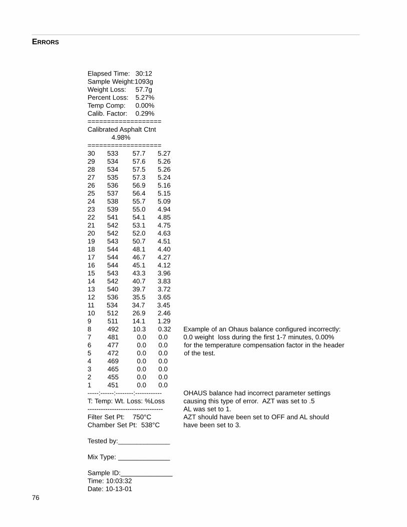
76
Elapsed Time: 30:12Sample Weight:1093gWeight Loss: 57.7gPercent Loss: 5.27%Temp Comp: 0.00%Calib. Factor: 0.29%===================Calibrated Asphalt Ctnt
4.98%===================30 533 57.7 5.2729 534 57.6 5.2628 534 57.5 5.2627 535 57.3 5.2426 536 56.9 5.1625 537 56.4 5.1524 538 55.7 5.0923 539 55.0 4.94 22 541 54.1 4.8521 542 53.1 4.7520 542 52.0 4.6319 543 50.7 4.51 18 544 48.1 4.4017 544 46.7 4.2716 544 45.1 4.1215 543 43.3 3.96 14 542 40.7 3.83 13 540 39.7 3.7212 536 35.5 3.6511 534 34.7 3.4510 512 26.9 2.469 511 14.1 1.298 492 10.3 0.32 Example of an Ohaus balance configured incorrectly:7 481 0.0 0.0 0.0 weight loss during the first 1-7 minutes, 0.00% 6 477 0.0 0.0 for the temperature compensation factor in the header 5 472 0.0 0.0 of the test.4 469 0.0 0.0 3 465 0.0 0.0 2 455 0.0 0.0 1 451 0.0 0.0 -----:------:--------:------------ OHAUS balance had incorrect parameter settingsT: Temp: Wt. Loss: %Loss causing this type of error. AZT was set to .5---------------------------------- AL was set to 1.Filter Set Pt: 750°C AZT should have been set to OFF and AL shouldChamber Set Pt: 538°C have been set to 3.
Tested by:______________
Mix Type: ______________
Sample ID:______________Time: 10:03:32Date: 10-13-01
ERRORS

Elapsed Time: 30:12Sample Weight:1093gWeight Loss: 0.8gPercent Loss: 0.03%Temp Comp: 0.00%Calib. Factor: 0.00%Bitumen Ratio: 0.03%===================Calibrated Asphalt Ctnt
0.03%===================30 533 0.8 0.0329 534 0.8 0.0328 534 0.8 0.0327 535 0.8 0.0326 536 0.8 0.0325 537 0.8 0.03 24 538 0.8 0.0323 539 0.7 0.03 22 541 0.7 0.03 21 542 0.7 0.03 20 542 0.7 0.03 19 543 0.7 0.0318 544 0.7 0.03 An example of the time/date function of the balance not17 544 0.6 0.02 properly set. The decimal place is actually moved 4 digits 16 544 0.6 0.02 to the left.15 543 0.6 0.0214 542 0.6 0.0213 540 0.6 0.0212 536 0.6 0.0211 534 0.6 0.0210 512 0.5 0.029 511 0.5 0.028 492 0.5 0.027 481 0.5 0.02 6 477 0.4 0.01 5 472 0.4 0.01 4 469 0.2 0.013 465 0.2 0.01 2 455 0.1 0.011 451 0.1 0.01-----:------:--------:------------T: Temp: Wt. Loss: %Loss ----------------------------------Filter Set Pt: 750°CChamber Set Pt: 538°C
Tested by:______________
Mix Type: ______________
Sample ID:______________Time: 10:03:32Date: 10-13-01
ERRORS
77

78
Elapsed Time: 30:12Sample Weight:1093gWeight Loss: 0.8gPercent Loss: 0.03%Temp Comp: 0.00%Calib. Factor: 0.00%Bitumen Ratio: 0.03%===================Calibrated Asphalt Ctnt
0.03%===================
0.00%0.00%0.00%0.00%0.00%0.00%0.00%0.00%0.00%0.00%0.00%0.00%0.00%0.00% An I.C. chip on the main PC board was not properly placed0.00% in the socket; causing the print out to look like this.0.00%0.00%0.00%0.00%0.00%0.00%0.00%0.00%0.00%0.00%0.00%0.00%0.00%
-----:------:--------:------------T: Temp: Wt. Loss: %Loss ----------------------------------Filter Set Pt: 750°CChamber Set Pt: 538°C
Tested by:______________
Mix Type: ______________
Sample ID:______________Time: 10:03:32Date: 10-13-01
ERRORS

79
Elapsed Time: 30:12Sample Weight:1093gWeight Loss: 57.7gPercent Loss: 5.27%Temp Comp: 0.13%Calib. Factor: 0.00%===================Calibrated Asphalt Ctnt
4.98%===================30 533 14.7 1.9929 534 32.2 3.14 28 534 57.5 5.2627 535 108.6 8.8126 536 56.9 5.1625 537 56.4 5.1524 538 107.2 8.8023 539 55.0 4.94 22 541 54.1 4.8521 542 1.14 2.3320 542 17.6 2.0119 543 50.7 4.51 18 544 48.1 4.4017 544 175.2 9.9816 544 45.1 4.1215 543 43.3 3.96 14 542 0.05 0.01 13 540 39.7 3.7212 536 175.1 11.411 534 12.1 2.4410 512 26.9 2.469 511 14.1 1.298 492 10.3 0.32 Balance plate is catching or the support columns holding7 481 102.5 3.31 the balance plate is rubbing against the sides causing the 6 477 10.1 2.22 balance to bounce in weight loss. The basket could also5 472 17.2 0.02 be rubbing the sides of the chamber.4 469 15.0 1.12 3 465 22.1 1.112 455 0.23 0.02 1 451 0.21 0.00-----:------:--------:------------T: Temp: Wt. Loss: %Loss ----------------------------------Filter Set Pt: 750°CChamber Set Pt: 538°CTested by:______________
Mix Type: ______________
Sample ID:______________Time: 10:03:32Date: 10-13-01
ERRORS

80
Elapsed Time: 30:12Sample Weight: 1093gWeight Loss: 57.7gPercent Loss: 5.27%Temp Comp: 0.14%Calib. Factor: 0.29%===================Calibrated Asphalt Ctnt
4.98%===================30 533 57.7 5.2729 534 57.6 5.2628 534 57.5 5.2627 535 57.3 5.2426 536 56.9 5.1625 537 56.4 5.1524 538 55.7 5.0923 539 55.0 4.94 22 541 54.1 4.8521 542 53.1 4.7520 542 52.0 4.6319 543 50.7 4.51 18 544 48.1 4.4017 544 25.7 4.2716 544 14.2 3.8915 543 10.3 3.32 The sample did not lose 15 grams in the first 15 minutes.14 542 9.9 2.21 This particular sample will run non-stop as a result!13 540 9.2 2.0112 536 8.9 1.9911 534 8.4 1.54 10 512 8.1 1.029 511 6.2 0.958 492 5.2 0.817 481 5.1 0.76 6 477 3.2 0.455 472 2.1 0.24 4 469 0.9 0.053 465 0.7 0.042 459 0.2 0.021 451 0.1 0.01-----:------:--------:------------T: Temp: Wt. Loss: %Loss ----------------------------------Filter Set Pt: 750°CChamber Set Pt: 538°C
Tested by:______________
Mix Type: ______________
Sample ID:______________Time: 10:03:32Date: 10-13-01
ERRORS

81
Removal of the ControlAssembly (Bottom Section) inthe 1087 & 1275 Series NCATThe control assembly is the lower section of the furnace.It houses all the P.C. boards, relays, the balance, andwire assemblies. When the front control panel (keypad)is lowered, you can look into the electronic control hous-ing. The control assembly, if properly disconnected, canbe slid out of the back of the unit.
To disconnect the control panel:1. Remove the eight screws along the lower, out-
side back wall secure the control assembly fromthe back. They are located from the lower left-hand corner, across the top of the control sec-tion, and the lower right-hand corner of the unit.See photo. Screw placement is indicated bywhite X’s.
Equipment Test Procedure
8 screws to remove to slide out control panel.
Back of unit

82
2. Lowering the front panel, a washer/nut assemblycan be located at each corner (front right & frontleft, right behind the hinges the panel swingson). These nut assembles need to be loosenedbecause they hold down the bottom plenum ofthe control assemble. See photo. Nut/washerplacement is indicated by white X’s.
3. After the 2 nuts are loose in front and all eightscrews are removed from the back of the controlassembly, you can slide the control assemblyout of the back of the unit. (Notice the assemblywill only slide back for about an inch. Then itwill "get stuck". Do not continue to “tug” onthe assembly. The various wire harnesses willstop the control assembly from being able to beslide out completely. Jerking or tugging willcause wires to be separated from connectors!)
EQUIPMENT TEST PROCEDURE
2 nuts/washers to loosen to slide control panel out of unit.
Front of unit with control panel hinged downward

83
4. Next, unhook the wire harnesses that securesthe control assembly in place. IT IS VERYIMPORTANT THAT YOU NOTE WHEREEVERY WIRE HARNESS IS CONNECTEDBEFORE STARTING TO UNPLUG THEM.There are a total of TEN different wire harness-es in the front that need to be disconnected andone grounding strap. (See photo. Wire andstrap placement is indicated by white X’s.)Starting from the left (facing the unit), discon-nect the following:
a. Gray ribbon cable from the printer.
b. 2 red wires and two black wires running fromthe green power switch that needs to be discon-nected from the lower right hand corner of a sil-ver "box" (red wires go towards the balancewhen plugging back in).
c. On the upper left hand side of the same sil-ver "box", you will find 2 orange and 2 yellowwires that need to be disconnected. (Twoorange wires go towards the inside of the unitwhen you go to plug that connector back up.)They are the door switch wires.
EQUIPMENT TEST PROCEDURE
10 wires to disconnect, plus grounding strap to slide control panel out of unit
Front of unit with control panel hinged downward

84
d. There is a gray grounding-wire mounted tocontrol assembly floor and the swing down con-trol panel. One end needs to be released. Thebalance display board has 3 different wire har-nesses plugged into it.
e. A small gray ribbon running from the balanceto "P2" on the display board needs to beunplugged. (10-pin connector only plugs backin one way).
f. There is a red and white DC adapter labeled"P6".
g. A second gray ribbon connector labeled "P3".There is a special end on this harness that dis-tinguishes it from the others. The "L" shapedred display board only has two wire harnessesthat need to be removed.
h. A gray ribbon cable (14 pins). Located imme-diately next to the plastic ribbon cable for thekeypad.
i. The second harness to unplug is a 3-pin con-nector. 2 little black and 1 little red wire makesup this assembly.
j. On the far right hand side the unit; one har-ness needs to be unplugged. This harness has2 yellow wires, 1 purple wire, and 1 white wire.(Door switch and door-locking solenoid wires.)
EQUIPMENT TEST PROCEDURE

85
5. There are two wire harnesses that need to bedisconnected in the back of the unit. (Seephoto. Harness placement is indicated by whiteX’s.)
a. Locate a reddish-brown connector (for heat-ing elements). The harness consists of 3 whitewires and one green/yellow wire. Push the tabson the sides and gently-lift the connector up todisconnect.
b. The second wire harness in back consists of4 white wires for the cooling fans. Lift the tabup and gently-pull the connector apart
EQUIPMENT TEST PROCEDURE
2 wire harnesses to disconnect to slide control panel out of unit.
Back of unit - Control panel slid out 2.5”

86
6. Proceed to slide the control section out of theback of the unit. See photo below. As soon asthe control section is approximately half wayout, the thermocouple wires (Red and Yellow)will come into view and prevent the control sec-tion from sliding any further. The thermocoupleconnectors are green, the connectors also havea "C" for chamber, and "F" for filter printed onthem, disconnect each one.
EQUIPMENT TEST PROCEDURE
Control panel slid out 1/2 way
2 wire harnesses to disconnect to slide control panel out of unit.

87
7. The complete control assemble will slide all theway out now.
8. To reinstall the control panel, perform the samesteps in the reverse order. (Remember to plugyour thermocouple wires back in as you slidethe control section back into the unit.)
The biggest cause of failure when reinstalling the controlsection is having wire harnesses that are not plugged inproperly. TIP: Do not ever "tug" on wires in an attempt todisconnect them. Some harnesses have tabs that needto be released in order for the harness to slide freelyapart. TIP: Labeling wires prior to disconnecting will aidin reconnection.
EQUIPMENT TEST PROCEDURE
Control section pulled from unit

1087 Series Back WallInsulation Removal
Procedure to remove/replace JC1087X3Tools needed:
- Phillips screw-driver (power screw driver is available)- Flat head screw-driver & Needle nose pliers- Refer to drawings "ZD", "ZC, & "ZB" at theback of this manual for pictorials.
1. Disconnect unit from power source.
2. Detach the exhaust tubing from blower motor.
3. Position unit in an area where all four sides canbe easily accessed.
4. Remove the back cover of the chamber section(CV 1087X10)
5. Remove the filter thermocouple (upper thermo-couple - TC1087X1), taking care not to physical-ly break the thermocouple (back of unit).
6. Remove the chamber thermocouple (lower ther-mocouple - TC859X1A), taking care not to phys-ically break the thermocouple (back of unit).
7. Loosen the screws that secure the afterburnerelement lead wires on each terminal block (backof unit).
8. Loosen the screws that secure the top, bothsides, and bottom heating element lead wires oneach terminal block (back of unit).
9. Detach blower motor wire harness.
10. Remove the top cover assemble (CV1087X15 &CV1087X13)
11. Remove metal sheet cover (CV1087X1)
88
EQUIPMENT TEST PROCEDURE
WarningUnit should be at ambient tempera-ture before attempting to replace theback wall insulation.
WarningUnit should be disconnected fromthe power source before attemptingto replace the back wall insulation.

12. Remove blanket insulation (JC1087X7)
13. Remove insulation material (JC1087X4)
14. Remove afterburner element (EL1087X1)
15. Remove the filter (FL859X2)
16. Remove insulation material (JC1087X4)
17. Remove metal brace (BC1087X13)
18. Open chamber door
19. Remove top element (slide/pull out of chamberfrom the front) (EL1087X3)
20. Remove both side elements (slide/pull out ofchamber from the front) (EL859X3 & EL859X4)
21. Remove the bottom element (slide/pull out ofthe chamber from the front) (EL1087X2)
22. Remove the back wall ceramic piece (PH412X1)
23. Remove the back wall insulation piece(JC1087X3)
Install the replacement JC1087X3 (position into place).By following the procedure to remove the JC1087X3 inthe reverse order, the NCAT can be put back together.
Heating ElementsA) Heating Elements (Quick & Simple Test)**This test must be preformed with the chamber at room(ambient) temperature.
Equipment needed: - None
1) Power up the NCAT unit.
2) Allow the NCAT to step through the startupcountdown and go into the preheat mode. Note
89
EQUIPMENT TEST PROCEDURE
NoteRefer to the pictures and parts list inthe back of this manual.

when the CYCLE FILTER and CYCLE CHAM-BER LED’s illuminate on the front control panel.
3) Allow the NCAT to heat for 30 seconds.
a) The 30 seconds begin when the CYCLEFILTER and CYCLE CHAMBER LED’s illumi-nate.
4) Power off the NCAT unit.
5) Open the chamber door and physically feel thetop, sides, and bottom of the chamber with yourhand. CAUTION: Element may be hot!
a) An element that is generating heat will bewarm to the touch. An element that is not gen-erating heat will be cold to the touch. Becauseof the series/parallel relationship of the elementsin the circuit, this test method will not isolatewhich cold element is actually burned out andwhat cold element may still be good.
***The afterburner element in the 1087 or 1275 seriesNCAT can not be tested in this manner because the sur-face area of the element is embedded in the top plenumof the chamber.
B) Heating Elements (ohm check performed withoutpower applied to the unit)
Equipment needed:- Digital ohm meter (DMM)- Phillips screw driver- Flat-head screw driver- NCAT Element Configuration print
1) Disconnect the NCAT unit from the powersource.
2) Remove the back panel from the NCAT
a) 14 screws around the outer edges hold the backpanel in place (4 on each side, top & bottom).
3) Loosen and remove the screws and nuts thathold down the element lead wire on each termi-nal block. Refer to page 94.
90
EQUIPMENT TEST PROCEDURE
CautionThe internal walls are the actual heat-ing elements and may be to hot totouch if the unit was allowed to heatfor more than 30 seconds or thechamber was not at ambient condi-tion to begin with.

91
4) Open the chamber door and slide the top ele-ment straight out the front of the unit.
5) Remove the each side element in the samefashion. Refer to photos on page 94.
6) Remove the bottom element in the same fash-ion.
7) The afterburner element in the 1087 series unitscan remain in the unit
8) Measure the resistance between the elementlead wires on each element with an ohmmeter.Refer to chart on page 95 to obtain element coldresistance value.
9) If the cold resistance of each element is off bymore than 10 ohms, element replacement isneeded.
***When reinstalling the elements, the bottom elementmust be slid into position first, followed by each side &finally the top element.
EQUIPMENT TEST PROCEDURE
Element removal (top element shown)

92

93

94
EQUIPMENT TEST PROCEDURE
A
B
C D
E
F G
H
I
Key DescriptionA Element terminal blocksB Element terminal blocksC Element terminal blocksD Element terminal blocksE Element terminal blocksF Element terminal blocksG Element terminal blocksH Filter thermocouplerI Chamber thermocoupler
1087 or 1275 series back view
Element lead wire
Element terminal block close up
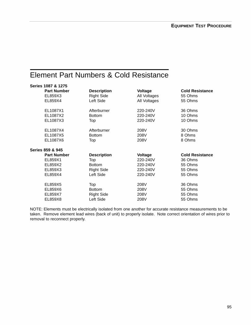
95
Element Part Numbers & Cold ResistanceSeries 1087 & 1275
Part Number Description Voltage Cold ResistanceEL859X3 Right Side All Voltages 55 OhmsEL859X4 Left Side All Voltages 55 Ohms
EL1087X1 Afterburner 220-240V 36 OhmsEL1087X2 Bottom 220-240V 10 OhmsEL1087X3 Top 220-240V 10 Ohms
EL1087X4 Afterburner 208V 30 OhmsEL1087X5 Bottom 208V 8 OhmsEL1087X6 Top 208V 8 Ohms
Series 859 & 945Part Number Description Voltage Cold ResistanceEL859X1 Top 220-240V 36 OhmsEL859X2 Bottom 220-240V 55 OhmsEL859X3 Right Side 220-240V 55 OhmsEL859X4 Left Side 220-240V 55 Ohms
EL859X5 Top 208V 36 OhmsEL859X6 Bottom 208V 55 OhmsEL859X7 Right Side 208V 55 OhmsEL859X8 Left Side 208V 55 Ohms
NOTE: Elements must be electrically isolated from one another for accurate resistance measurements to betaken. Remove element lead wires (back of unit) to properly isolate. Note correct orientation of wires prior toremoval to reconnect properly.
EQUIPMENT TEST PROCEDURE

96

97

98
ThermocouplesThe NCAT utilizes two type K thermocouples. Onethermocouple is routed into the back of the chamber.The other is routed into the top plenum (filter).
A type K thermocouple generates a millivolt signal. Asthe temperature rises in the chamber and filter section,the millivolt signal generated by the thermocoupleincreases. The generated millivolt signal is utilized bythe main microprocessor to detect chamber and filtertemperature changes.
A type K thermocouple is manufactured with nickel-chromium and nickel-aluminum wires and has definitepolarity (positive and negatively charged wires). Thenegative wire has a RED insulator sleeve. The posi-tive wire has a YELLOW insulator sleeve and a (+)sticker. It is also marked with a black indicator mark onthe terminal end of the actual wire itself. BarnsteadInternational recommends replacing the chamber andfilter thermocouples every 12 months.
A) Chamber ThermocoupleEquipment needed:
- Digital ohm meter or continuity tester- Phillips screw driver
1) Disconnect the NCAT from the power source.
2) The chamber must be at ambient tempera-ture to properly test the thermocouple. Allowunit to cool to ambient if necessary.
3) Remove the back panel from the NCAT.
a) 14 screws around the outer edges holdthe back panel in place (4 on each side, top& bottom).
4) Disconnect the chamber thermocouple fromthe terminal block located near themiddle/bottom of the back of the chamber.
a) The thermocouple has a yellow and redwire that run lengthwise up the back of thechamber wall, entering into the chamberapproximately half way up the back wall.
EQUIPMENT TEST PROCEDURE
A
B
C D
E
F G
H
I
Key DescriptionA Element terminal blocksB Element terminal blocksC Element terminal blocksD Element terminal blocksE Element terminal blocksF Element terminal blocksG Element terminal blocksH Filter thermocouplerI Chamber thermocoupler
1087 or 1275 series back view

99
b) This will electrically isolate the thermocouple fromthe rest of the circuitry.
c) It is important to label or note the color of the wireat the terminal block connection for polarity purpos-es.
5) Using a continuity tester, measure across the leadwires of the thermocouple.
a) A good thermocouple will have a very low resist-ance measurement or continuity.
6) Replace the thermocouple if it does not exhibit lowresistance or continuity.
B) Filter ThermocoupleEquipment needed:
- Digital ohm meter or continuity tester- Phillips screw driver
1) The filter thermocouple is tested in the same man-ner as the chamber thermocouple.
a) The filter thermocouple is connected to the sameterminal block located near the middle/bottom of theback of the chamber. However, the lead wires runlengthwise up the back wall of the chamber, protrud-ing into the NCAT near the very top.
2) Disconnect the yellow and red lead wires from theterminal block. This will electrically isolate the ther-mocouple.
a) It is important to label or note the colors of thewires at the terminal block connection for polaritypurposes.
3) Using a continuity tester, measure across the leadwires of the thermocouple.
4) A good thermocouple will have a very low resistancemeasurement or continuity.
EQUIPMENT TEST PROCEDURE

100
5) Replace the thermocouple if it has high resist-ance or no continuity.
**Do not attempt to connect a voltmeter in parallel witheither thermocouple, attempting to monitor the millivolt-generated signal. A meter will load the circuit, resulting ininaccurate measurements.
EQUIPMENT TEST PROCEDURE

Solid State RelaysThere are a total of three solid-state relays in the NCAT.All three are located in the lower control section. Refer tophoto of keypads on page 38. The solid state relays,activated by a 5 - 15Vdc signal from the main micro-processor P.C. board, act as switches that allow AC volt-age to the chamber heating elements, filter element(afterburner), and blower motor (exhaust fan).
A) Solid State Relay Equipment needed:
- Digital voltmeter (DMM)- Phillips screw driver
1) Disconnect the NCAT unit from the powersource.
2) Remove the eight screws from the back of thecontrol section.
a) There are 4 screws along the top of the controlsection and 2 on each side.
3) Lower the control panel (keypad) in the front ofthe NCAT.
a) There are 4 screws along the top of the con-trol panel.
b) The control panel hinges from the bottom.
4) Loosen two nuts on the bottom, front edge ofthe control section.
101
EQUIPMENT TEST PROCEDURE
Solid State Relays

102
a) Each nut is physically located 1/2” to 1”directly behind the hinges. These nuts securethe control section to the front of the NCAT.
5) The control panel will slide out from the backside of the NCAT (Approximately 2” out from theunit.)
a) It is important not to pull the control sectiontoo far back with force, as several wire harness-es are still connected securing the control sec-tion in the NCAT.
6) The solid-state relays are now visible, mountedon the back wall, on the lower left side (a heatsink device is mounted on the outside of theNCAT). See photo on previous page.
a) The relay on the far left side is for the blowermotor (exhaust fan). This relay will have twoblack wires connected to pins “1” and “2”; a yel-low wire to pin “3”; and a green wire to pin “4”.
b) The relay in the middle is for the chamberelements. This relay will have two white wiresconnected to pins “1” and “2”; a red wire to pin“3”; and a black wire to pin “4”.
c) The relay on the right side (near the center ofthe furnace) is for the filter element (afterburn-er). This relay will have two white wires con-nected to pins “1” and “2”; an orange wire to pin“3”; and a brown wire to pin “4”.
7) Connect the voltmeter leads to terminal pinsnumber 3 and 4 of the solid-state relay. CAU-TION: You will also be measuring live voltage, apotential shock hazard!
a) Each relay has 4 screw terminals, eachlabeled “1”, “2”, “3”, “4”. Terminal pins “1” and“2” on all three relays are considered the outputand will only have AC voltage across them atvarious times of operation. Terminal pins “3”and “4” on all three relays are considered theinput and will only have DC voltage across themat various times of operation. Pin “3” is the DC
EQUIPMENT TEST PROCEDURE

103
positive terminal. Pin “4” is the DC negative ter-minal. Refer to page 96.
8) Power on the NCAT unit.
9) Allow the NCAT to step through the startupcountdown and go into the preheat mode.
10) Note if the CYCLE FILTER and CYCLE CHAM-BER LED’s illuminate on the front control panel.
a) These LED’s indicate the main microproces-sor control board is attempting to apply power tothe solid-state relays. If they are not illuminated,the solid-state relays should not have powerapplied to them and the main logic board maybe defective.
11) How to determine if a solid-state relay is defec-tive:
a) A solid state relay can be considered good, ifthe input of the relays (pins “3” and “4”) have a5 to 15Vdc signal applied across them and atthe same time no AC voltage can be measuredacross pins “1” and “2”.
b) A solid-state relay is also considered good, ifthe input of relay, pins “3” and “4”, have no DCvoltage signal applied across them and at thesame time an AC voltage can be measuredacross pins “1” and “2”.
c) A solid state relay is considered defective, ifthe input of the relays (pins “3” and “4”) have a5 to 15Vdc signal applied across them and atthe same time full potential line voltage (AC) canbe measured across output pins “1” and “2”.
12) To test the blower motor (exhaust fan) solid-state relay, activate the blower motor by press-ing the start/stop key to initiate a cycle run.(The blower motor is not activated in the preheatmode. Only when a cycle is being run in thetest mode!) If the blower motor turns on, your
EQUIPMENT TEST PROCEDURE

104
solid-state relay is working properly. Taking voltagemeasurements at this point is not necessary.However, if the blower motor does not run or is run-ning while the NCAT is in the preheat mode, thesolid-state relay may be defective. Take voltagemeasurements as described in step 11 to determineif the solid-state relay is defective.
KeypadA) KeypadEquipment needed:
- Phillips screw driver- Jumper wires or needle nose pliers
1) Disconnect the NCAT unit from the power source.
2) Lower the control panel by removing the 4 screwsalong the top edge. Control panel hinges down-ward.
3) Locate and disconnect keypad from J2 terminal ofdisplay board.
4) Reconnect the NCAT to the power source.
5) Use jumper wires or needle nose pliers to short twopins together on the J2 display board to simulatepressing a key. (Use the matrix chart below to iden-tify what to pins to short out to simulate a key-stroke.)
a) The J2 terminal is an 8 pin electrical connectionpoint. Connection terminal is orientated such thatpin 1 is nearest D7 and pin 8 is nearest the J1 con-nection terminal.
EQUIPMENT TEST PROCEDURE

b) Matrix chart:
105
EQUIPMENT TEST PROCEDURE
7 Key • •
8 Key • •
9 Key • •
Temp Key • •
4 Key • •
5 Key • •
6 Key • •
Weight Key • •
1 Key • •
2 Key • •
3 Key • •
Cal. Key • •
Timer Key • •
0 Key • •
Start/Stop • •
Enter Key • •
Pin 1 Pin 2 Pin 3 Pin 4 Pin 5 Pin 6 Pin 7 Pin 8

106
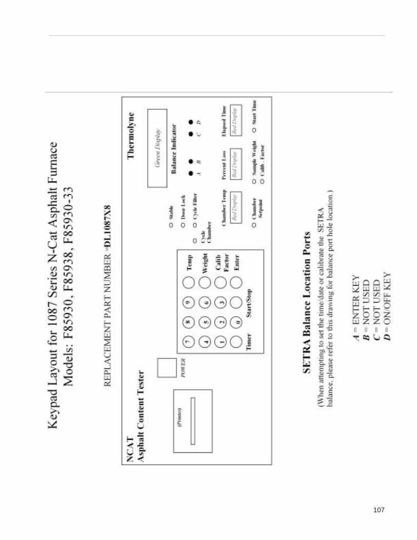
107

108

109

Lift Test ProcedureThe efficiency of the blower and/or exhaust system ismonitored by a quick test procedure, referred to as the“lift test”. Steps to perform a lift test:
1. Chamber must be at ambient (room tempera-ture) condition before attempting to perform a lifttest.
a) Allow the unit to cool to ambient condition.
2. Press the green power button on front display.
a) Allow the unit to complete the diagnostic testupon power up.
3. Press the “0” key on the keypad.
a) This zeros the balance.
4. Press the “start/stop” key on the keypad.
a) This initiates the blower motor.
5. The green display will indicate a numberapproximately 20 seconds after pressing the“start/stop” key.
a) This number is the negative lift.
6. Record the number on paper.
a) Ideally, the number should be between –3.0and –8.2
b) Detach the exhaust tubing and repeat the testto determine if the exhaust system is restrictingthe airflow or if the top plenum of the NCAT isrestricting the airflow.
7. Refer to the NCAT cleaning procedure if the lifttest falls out of this range.
110
Maintenance

Cleaning Procedure for NCATThe NCAT unit must be kept clean in order to ensureproper operation. The lift test procedure is a tool to indi-cate when the unit needs to be cleaned. (See Lift TestProcedure) Follow the instructions below for propercleaning. Cleaning routine should be started with NCATat room temperature.
1. Disconnect power. Disassemble the top venttube from the blower motor. Using a Shop-Vac,clean out the vent tube of all soot build up.Shop-Vac the chamber as well, if needed.
2. Remove the top cover of furnace and oil theblower motor with Anderoll 465 lubricant (partnumber AYX6).
3. Open the chamber door. Inspect the door insu-lation for black streaks of soot. (Usually runningfrom the outside corners of the insulationtowards the center.) If black streaks are pres-ent, it is a sign the door is loose and the cham-ber is sucking in air. (If there is no black streaksthen continue to step 4.) Tighten the door byopening it at a 90-degree angle in reference tothe front of the chamber. Loosen the door hingescrews and push the edge of the door into thefront left edge of the chamber. Tighten downthe hinge screws while the door is being pushedin, towards the front left edge of thechamber/hinges. Replacing the door insulationmaybe necessary (part number JC412X10,quantity to order = 4).
4. In the 1087 and 1275 series NCATs there is ahole in the back of the chamber. This hole isthe opening that extends upward into the topplenum. It acts like a chimney to preventsmoke buildup in the chamber. Ensure thischimney is free of any soot buildup. A pipecleaner or stiff wire can be used to clean out thechimney. NOTE: This piece of insulation mayneed to be replaced if lift tests remain out ofspec after this entire cleaning procedure is exe-cuted. (See troubleshooting section for moredetails.)
MAINTENANCE
111

5. Reconnect power. Increase the chamber setpoint temperature to 650°C using the chamberset button. Increase the filter set point tempera-ture to 900°C by performing a hidden key 5 tochange filter set point temperature as follows:Turn the green power switch “off”. Press andhold the #5 key in while pressing the greenpower switch. Once the furnace “beeps”releasethe #5 key.)
6. Allow the unit to reach and maintain the650°C/900°C condition for at least 3 hours.(The furnace has a course filter in the topplenum that will burn itself clean.) Do not initi-ate a cycle, let the unit in the idle mode for theduration.
7. After this 3-hour period, reset the chamber tem-perature to your desired burning level. Resetthe filter temperature to 750°C by performing thehidden key #5 routine.
Routine cleaning of the NCAT is complete.
Chamber TemperatureVerification/CalibrationNCAT Specifications:
Chamber Size = 14” x 14” x 14”Chamber max set point = 650°CFilter max set point = 900°CFactory default set point temperatures = 538°C chamber; 750°C filter
NOTE: The 859 or 945 Series NCATS do not have apredrilled calibration port. Customer may need to removeback cover and drill their own 1/4” diameter port throughthe back wall. View page 115 for a view of the back ofthe unit and the location of the port.
NOTE: 1087 & 1275 series NCATS have a predrilled cali-bration port-hole with an access cover on the back of thefurnace. You do not need to remove the back cover toaccess the port-hole.
112
MAINTENANCE

NOTE: It is not possible to calibrate or verify the filtertemperature of NCAT furnaces.
NOTE: To verify or calibrate chamber temperature, youwill need an N.I.S.T. traceable digital pyrometer(Barnstead International part number = PM20700) & anN.I.S.T. 10” Type K thermocouple probe (BarnsteadInternational part number TC405X2). These can be cali-brated to N.I.S.T. standards and shipped with a certifica-tion of calibration (Barnstead International part number =C5000) dated for 1 year. Calibration of the two testpieces of equipment will need to be performed every year.Contact Barnstead International for more details at 800-553-0039
NOTE: Chamber temperature calibration should only beperformed in the IDLE mode. Attempting calibration inthe TEST mode will produce inaccurate results primarilybecause the exhaust fan is activated in the TEST mode,pulling ambient air (approximately 10CFM) through thechamber.
Chamber Temperature CalibrationProcedure
PLEASE READ ENTIRE CALIBRATION PROCEDUREBEFORE PROCEEDING.
1. Power the NCAT on while holding the #5 key in(Hidden Key #5 routine). When the unit beeps,you may release the #5 key. The Hidden Key#5 routine will allow you change the filter setpoint temperature. Key in 500°C for the filter setpoint.
2. Cycle the power to the NCAT unit off and backon to exit the hidden key #5 routine and returnto idle mode.
3. Set the chamber temperature to 500°C.
4. Allow the unit to heat to the chamber/filter setpoint (approximately 2 hours) and stabilize foran additional 2 hours before proceeding.
5. Insert 10” Type K probe (B/I part numberTC405X4) through the temperature calibrationport on the back of the unit.
113
MAINTENANCE

114
6. Connect the probe to the digital pyrometer (B/Ipart number = PM20700) & power up thepyrometer.
7. Record the chamber temperature reading asindicated by the pyrometer.
8. Power off the NCAT.
9. Power the NCAT back up while holding the #3key in (Hidden Key #3 routine). When the unitbeeps, you may release the #3 key. The dis-plays will read “CHBR CAL” in the percent lossand elapsed time windows. The Hidden Key #3routine will allow you to key in the chamber tem-perature as measured by the pyrometer andrecorded in step 7.
10. Enter the new chamber temperature value(recorded in step 7) followed by pressing theenter key. The new offset value will be calculat-ed and the entered temperature value will bedisplayed. (The entered temperature is a tem-porary set point. The original set point willreturn upon exiting the hidden key #3 routine bypowering the unit off and back on.)
11. Power off the NCAT. (Green power switch)
12. Temperature calibration is now complete.
MAINTENANCE

115
- Chamber temperature should be +/- 10°C differencebetween unit temperature and probe temperature at500°C.
Back view of chamber section (859 & 945 series) withcover removed. A 1/4” diameter hole is predrilled throughthe stainless steel sheet metal but is not predrilledthrough the chamber insulation material. A 1/4” diameterhole must be drilled through the insulation material toaccess the chamber.
Balance CalibrationPlease refer to the “Balance” section of this manual forcomplete calibration procedures.
MAINTENANCE
10.5”
Type K ChamberThermocoupleL i
CalibrationPort

* No
te th
e or
ient
atio
n of
th
e ho
les
in th
ese
piec
es.
The
hole
s m
ust b
e
re-a
ligne
d pr
oper
ly
when
put
ting
unit
ba
ck to
geth
er.
**
*
**
**
**
*
**
**
*
**
**
*
Scre
ws
Insu
latio
n m
ater
ial
(Har
der m
ater
ial)
Scre
ws
Met
al s
heet
cov
er
Blan
ket I
nsul
atio
n
Side
ele
men
t(2
40 V
)
Insu
latio
n m
ater
ial
(Har
der m
ater
ial)
Cour
se
Filte
r
Afte
rbur
ner E
lem
ent
Insu
lato
rs
Side
wal
l ins
ulat
ion
Side
wal
l in
sula
tion
Top
elem
ent (
240V
)
Insu
lato
rs
Back
wal
lhe
arth
Back
wal
lin
sula
tion
Chim
ney-
like
Por
t
Blan
ket i
nsul
atio
n
Met
al b
race
/bra
cket
Met
al b
ack
wall
Side
Insu
latio
n
Botto
m e
lem
ent
(240
V)
Side
ele
men
t(2
40V)
Drawings
RE
F. “
ZB
”

Filte
r Th
erm
ocou
ple
Cham
ber
Ther
moc
oupl
e
BACK
OF
UNIT
* *
* *
**
*Te
rmin
al b
lock
s th
at s
ecur
e el
emen
t lea
d wi
res
Cham
ber T
.C.
Filte
r T.C
.
*
*
*
*
Elem
ent l
ead
wire
s ar
e "p
inch
ed" b
etwe
enth
e te
rmin
al b
lock
and
a s
mal
l fla
p of
met
al.
To lo
osen
lead
wire
s, lo
osen
scr
ews
and
nuts
that
hol
d th
e m
etal
flap
aga
inst
the
term
inal
blo
ck.
Air
Defle
ctor
Afte
rbur
ner e
lem
ent
lead
wire
s
Back
of u
nit
DRAWINGS
RE
F. “
ZC
”

Back
of
unit
Nuts
Was
her
Brac
ket
Top
Cove
rCV
1087
X15
Top
Cove
rCV
1087
X13
Blow
er M
otor
Harn
ess
to d
isco
nnec
tbl
ower
mot
or
Scre
ws
Met
al c
over
Back
cov
erch
ambe
r sec
tion
Tem
pera
ture
prob
e po
rt
DRAWINGS
RE
F. “
ZD
”