low voltage rear connected switchboard - siemens … voltage rear connected switchboard selection...
TRANSCRIPT
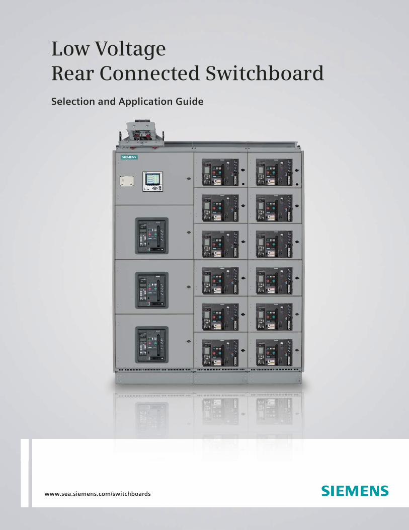
Low Voltage Rear Connected SwitchboardSelection and Application Guide
www.sea.siemens.com/switchboards
Table of ContentsType RCS Rear Connected Switchboards
General Information . . . . . . . . . . . . . . . . . . . . . . . . . . . . . . . . . . . . . . . . . . . . . . . . . . . . . . . . . . . . . . . . . . . . . . . . . . . . . . . . . . . 2 Construction Details . . . . . . . . . . . . . . . . . . . . . . . . . . . . . . . . . . . . . . . . . . . . . . . . . . . . . . . . . . . . . . . . . . . . . . . . . . . . . . . . 3 – 5WL Circuit Breaker . . . . . . . . . . . . . . . . . . . . . . . . . . . . . . . . . . . . . . . . . . . . . . . . . . . . . . . . . . . . . . . . . . . . . . . . . . . . . . . . . . . . . 6 Electronic Trip Unit . . . . . . . . . . . . . . . . . . . . . . . . . . . . . . . . . . . . . . . . . . . . . . . . . . . . . . . . . . . . . . . . . . . . . . . . . . . . . . . . . 7 – 9Time/Current Characteristic Curves . . . . . . . . . . . . . . . . . . . . . . . . . . . . . . . . . . . . . . . . . . . . . . . . . . . . . . . . . . . . . . . . . . 10 – 12Breaker Technical Data . . . . . . . . . . . . . . . . . . . . . . . . . . . . . . . . . . . . . . . . . . . . . . . . . . . . . . . . . . . . . . . . . . . . . . . . . . . . 13 – 27 WL Secondary Terminal Assignments . . . . . . . . . . . . . . . . . . . . . . . . . . . . . . . . . . . . . . . . . . . . . . . . . . . . . . . . . . . . . . . . . . . . . 28WL Communication Overview . . . . . . . . . . . . . . . . . . . . . . . . . . . . . . . . . . . . . . . . . . . . . . . . . . . . . . . . . . . . . . . . . . . . . . . . . . . 29Section Configurations . . . . . . . . . . . . . . . . . . . . . . . . . . . . . . . . . . . . . . . . . . . . . . . . . . . . . . . . . . . . . . . . . . . . . . . . . . . . 30 – 32Shipping Weights and Dimensional Information . . . . . . . . . . . . . . . . . . . . . . . . . . . . . . . . . . . . . . . . . . . . . . . . . . . . . . . . 33 – 37VT, CPT, CT Data . . . . . . . . . . . . . . . . . . . . . . . . . . . . . . . . . . . . . . . . . . . . . . . . . . . . . . . . . . . . . . . . . . . . . . . . . . . . . . . . . . . . . . 38Guide Form Specifications . . . . . . . . . . . . . . . . . . . . . . . . . . . . . . . . . . . . . . . . . . . . . . . . . . . . . . . . . . . . . . . . . . . . . . . . . 39 – 43
General InformationType RCS Rear Connected Switchboards
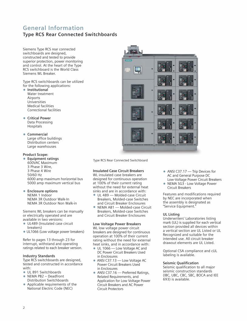
Siemens Type RCS rear connectedswitchboards are designed, constructed and tested to providesuperior protection, power monitoringand control. At the heart of the TypeRCS switchboard is the World ClassSiemens WL Breaker.
Type RCS switchboards can be utilizedfor the following applications:• Institutional
Water treatmentAirportsUniversitiesMedical facilitiesCorrectional facilities
• Critical PowerData ProcessingHospitals
• CommercialLarge office buildingsDistribution centersLarge warehouses
Product Scope:• Equipment ratings
600VAC Maximum3 Phase 3 Wire, 3 Phase 4 Wire50/60 Hz6000 amp maximum horizontal bus5000 amp maximum vertical bus
• Enclosure optionsNEMA 1 IndoorNEMA 3R Outdoor Walk-InNEMA 3R Outdoor Non Walk-in
Siemens WL breakers can be manuallyor electrically operated and are available in two versions:• UL489 (Insulated case circuit
breakers)• UL1066 (Low voltage power breakers)
Refer to pages 13 through 23 forinterrupt, withstand and operating ratings related to each breaker version.
Industry StandardsType RCS switchboards are designed,tested and constructed in accordancewith:• UL 891 Switchboards• NEMA PB2 – Deadfront
Distribution Switchboards• Applicable requirements of the
National Electric Code (NEC)
Insulated Case Circuit BreakersWL insulated case breakers aredesigned for continuous operation at 100% of their current rating without the need for external heatsinks and are in accordance with:• UL 489 — Molded-case Circuit
Breakers, Molded-case Switches and Circuit Breaker Enclosures
• NEMA AB1 — Molded-case Circuit Breakers, Molded-case Switches and Circuit Breaker Enclosures
Low Voltage Power BreakersWL low voltage power circuit breakers are designed for continuousoperation at 100% of their current rating without the need for externalheat sinks, and in accordance with:• UL 1066 — Low Voltage AC and
DC Power Circuit Breakers Used in Enclosures
• ANSI C37.13 — Low Voltage AC Power Circuit Breakers Used in Enclosures
• ANSI C37.16 — Preferred Ratings, Related Requirements, and Application for Low Voltage Power Circuit Breakers and AC Power Circuit Protectors
• ANSI C37.17 — Trip Devices for AC and General Purpose DC Low-Voltage Power Circuit Breakers
• NEMA SG3 - Low Voltage Power Circuit Breakers
Features and modifications required by NEC are incorporated when the assembly is designated as “Service Equipment.”
UL Listing Underwriters’ Laboratories listingmark (UL) is supplied for each verticalsection provided all devices within a vertical section are UL Listed or ULRecognized and suitable for theintended use. All circuit breaker drawout elements are UL Listed.
Optional CSA compliance and cULlabeling is available.
Seismic QualificationSeismic qualification to all major seismic construction standards (IBC, UBC, CBC, SBC, BOCA and IEE693) is available.
2
Type RCS Rear Connected Switchboard
Construction DetailsType RCS Rear Connected Switchboards
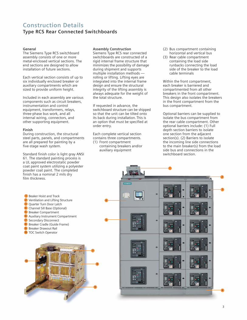
Beaker Hoist and TrackVentilation and Lifting StructureQuarter Turn Door LatchChannel Sill Base (Optional)Breaker CompartmentAuxiliary Instrument CompartmentSecondary DisconnectBreaker Cradle (Guide Frame)Breaker Drawout RailTOC Switch Operator
5
1
2
3
5
4
4
6
6
7
8
7
9
8
10
9
10
2
3
GeneralThe Siemens Type RCS switchboardassembly consists of one or more metal-enclosed vertical sections. Theend sections are designed to allowinstallation of future sections.
Each vertical section consists of up tosix individually enclosed breaker orauxiliary compartments which aresized to provide uniform height.
Included in each assembly are variouscomponents such as circuit breakers,instrumentation and control equipment, transformers, relays, three-phase bus work, and all internal wiring, connectors, and other supporting equipment.
FinishDuring construction, the structuralsteel parts, panels, and compartmentsare all prepared for painting by a five-stage wash system.
Standard finish color is light gray ANSI61. The standard painting process is a UL approved electrostatic powdercoat paint system utilizing a polyesterpowder coat paint. The completed finish has a nominal 2 mils dry film thickness.
Assembly ConstructionSiemens Type RCS rear connectedswitchboards are constructed of arigid internal frame structure thatminimizes the possibility of damageduring shipment and supports multiple installation methods —rolling or lifting. Lifting eyes are integrated into the internal framedesign and ensure the structuralintegrity of the lifting assembly isalways adequate for the weight of the total structure.
If requested in advance, the switchboard structure can be shippedso that the unit can be tilted onto its back during installation. This is an option that must be specified atorder entry.
Each complete vertical section contains three compartments.(1) Front compartment
containing breakers and/or auxiliary equipment
(2) Bus compartment containing horizontal and vertical bus
(3) Rear cable compartment containing the load side runbacks connecting the load side of the breaker to the load cable terminals
Within the front compartment, each breaker is barriered and compartmented from all other breakers in the front compartment.This design also isolates the breakersin the front compartment from thebus compartment.
Optional barriers can be supplied toisolate the bus compartment from the rear cable compartment. Otheroptional barriers include: (1) Fulldepth section barriers to isolate one section from the adjacent section(s). (2) Barriers to isolate the incoming line side connections to the main breaker(s) from the loadside bus and connections in theswitchboard section.
3
1
4
Construction DetailsType RCS Rear Connected Switchboards
Main and Ground BusThe standard main bus is silver-platedcopper. Tin-plated copper bus isoptionally available. Vertical and horizontal bus bar utilize a channelshape design to maximize short circuit withstand capability and minimize heat rise. All bus jointsinclude Grade 5 bolts and conicalspring washers. Provisions for futureextension of the main bus includeplated joints and high tensile strengthsteel hardware.
The main three-phase horizontal bus is arranged vertically one phaseabove the other with edge-to-edgealignment to provide high, short circuit strength. Insulated main buswith isolated vertical bus is optional.
Vertical bus ratings available are 800, 1200, 1600, 2000, 2500, 3000,3200, 4000, and 5000 amperes continuous current. Horizontal busratings available are 800, 1200, 1600, 2000, 2500, 3000, 3200,4000, 5000, and 6000 amperes. A neutral bus is furnished when specified, and can be rated 2500,3000, 4000, 5000, 6,000 or 8,000amperes continuous current.
A ¹⁄₄" X 3" standard copper ground busextends through all sections. Cablelugs are mounted to the ground busin each section.
Standard short circuit withstand (3 cycle) bus bracing is 100,000amperes. Optional 3 cycle short circuit withstand ratings of 150,000and 200,000 are available. Optional 4 cycle short circuit withstand ratings of 100,000, 150,000 and 200,000 are available. Optional 60 cycle shorttime withstand bus bracing rating of100,000 is also available.
Load side runbacks for feeder circuits are copper construction, insulatedwith sleeve tubing in the main busarea, and supported by high-strengthbus bracing.
Control and Communication WiringStandard control and communicationwiring is extra-flexible, stranded copper type MTW. Type SIS controland communication wiring is available as an option. Control and communication wiring is installed and accessed from the front of theswitchboard structure. Each breakercompartment has a dedicated horizontal and vertical wireway.
For devices not having screw-type terminals, pressure terminals are used.
InsulationThe insulation used is a UL recognizedthermoset or thermoplastic materialthat has excellent heat resistance,flame retardance, dimensional stability and low moisture absorption.
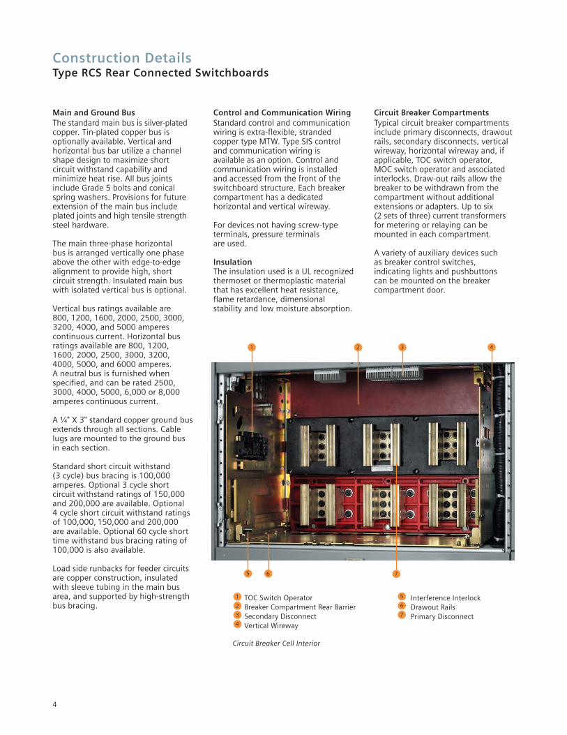
Circuit Breaker CompartmentsTypical circuit breaker compartmentsinclude primary disconnects, drawoutrails, secondary disconnects, vertical wireway, horizontal wireway and, if applicable, TOC switch operator, MOC switch operator and associatedinterlocks. Draw-out rails allow thebreaker to be withdrawn from thecompartment without additionalextensions or adapters. Up to six (2 sets of three) current transformersfor metering or relaying can bemounted in each compartment.
A variety of auxiliary devices such as breaker control switches, indicating lights and pushbuttons can be mounted on the breaker compartment door.
TOC Switch OperatorBreaker Compartment Rear BarrierSecondary DisconnectVertical Wireway
Interference InterlockDrawout RailsPrimary Disconnect
Circuit Breaker Cell Interior
4321
765
1
2
3
5
6
7
4
Construction DetailsType RCS Rear Connected Switchboards
Side View
Rear View
5
Options
Switchboard Mounted HoistThe integrally mounted hoist, standard on walk-in outdoor and optional on indoor switchboard enclosures, travelsalong rails on top of the switchboard toassist in breaker handling.
TOC and MOC SwitchesThe Truck Operated Cell (TOC) Switch provides interlocking controlor remote indication of the breaker racking position. The cubicle mounted auxiliary switch orMechanism Operated Cell (MOC)switch provides interlocking control or remote indication based on the main contact position (open or closed).
ShuttersThese provide protection against accidental contact with primary disconnects in a compartment when the breaker is removed. Shutters automatically close when the breaker is moved to the test position, disconnect position or iswithdrawn and are padlockable andfield installable.
Key InterlockThis provides a mechanical means foroperating circuit breakers and otherdevices only when predescribed conditions are met.
Test SetA portable breaker test set is availableas an option and supports testing thefull range of functions and protectivesettings supplied with the breaker trip unit.
Metering and AuxiliaryCompartmentsCompartments are available to housedevices such as voltage transformers,metering, control power transformers,and supervisory devices.
Instrument and ControlTransformers Voltage transformers and controlpower transformers are mounted in auxiliary compartments. These transformers are protected by primarypull-out type current-limiting fusesand secondary fuses. Current transformers are normally mounted
on the compartment primary disconnect studs where they arereadily accessible. See tables on page 37 for available ratings.
MiscellaneousEach switchboard lineup includes a breaker lifting device that isadjustable for use with Size 1, Size 2 and Size 3 breakers.
An optional portable breaker hoist is available if the integrated breakerhoist and track is not specified.
A test cabinet is also available as an option. The test cabinet is wallmounted necessary equipment fortesting electrically-operated breakersthat have been removed from thebreaker compartment.
4" high formed steel channel sills are available for indoor switchboardenclosures.
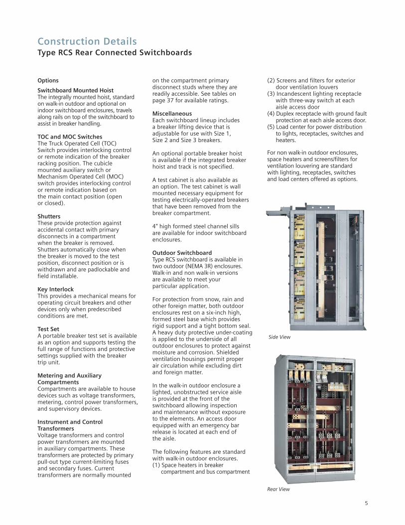
Outdoor SwitchboardType RCS switchboard is available intwo outdoor (NEMA 3R) enclosures.Walk-in and non walk-in versions are available to meet your particular application.
For protection from snow, rain and other foreign matter, both outdoor enclosures rest on a six-inch high, formed steel base which provides rigid support and a tight bottom seal.A heavy duty protective under-coatingis applied to the underside of all outdoor enclosures to protect againstmoisture and corrosion. Shielded ventilation housings permit proper air circulation while excluding dirt and foreign matter.
In the walk-in outdoor enclosure a lighted, unobstructed service aisle is provided at the front of the switchboard allowing inspection and maintenance without exposure to the elements. An access doorequipped with an emergency barrelease is located at each end of the aisle.
The following features are standard with walk-in outdoor enclosures.(1) Space heaters in breaker
compartment and bus compartment
(2) Screens and filters for exterior door ventilation louvers
(3) Incandescent lighting receptacle with three-way switch at each aisle access door
(4) Duplex receptacle with ground faultprotection at each aisle access door.
(5) Load center for power distribution to lights, receptacles, switches and heaters.
For non walk-in outdoor enclosures,space heaters and screens/filters for ventilation louvering are standard with lighting, receptacles, switches and load centers offered as options.
6
WL Circuit BreakerType RCS Rear Connected Switchboards
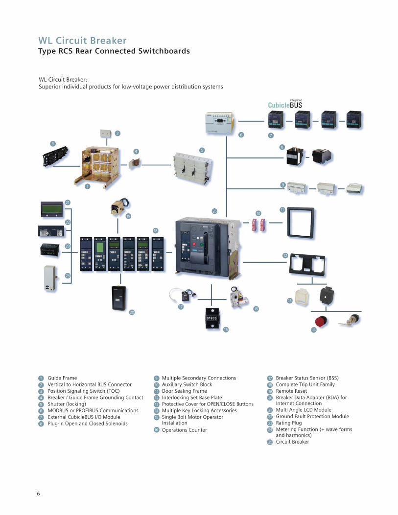
WL Circuit Breaker:Superior individual products for low-voltage power distribution systems
1
3
4 5
6 7
8
9
1011
12
13
14
15
16
17
18
19
20
21
22
23
24
25
9 Multiple Secondary Connections10 Auxiliary Switch Block11 Door Sealing Frame12 Interlocking Set Base Plate13 Protective Cover for OPEN/CLOSE Buttons14 Multiple Key Locking Accessories 15 Single Bolt Motor Operator
Installation16 Operations Counter
17 Breaker Status Sensor (BSS)18 Complete Trip Unit Family19 Remote Reset20 Breaker Data Adapter (BDA) for
Internet Connection21 Multi Angle LCD Module22 Ground Fault Protection Module23 Rating Plug24 Metering Function (+ wave forms
and harmonics)25 Circuit Breaker
1 Guide Frame2 Vertical to Horizontal BUS Connector3 Position Signaling Switch (TOC)4 Breaker / Guide Frame Grounding Contact5 Shutter (locking)6 MODBUS or PROFIBUS Communications7 External CubicleBUS I/O Module8 Plug-In Open and Closed Solenoids
2
Electronic Trip UnitType RCS Rear Connected Switchboards
Electronic Trip Unit During development of our electronictrip units we have consistently strivento ensure modularity. The following are just some of the modules that aresimple to retrofit at any time:
• Ground fault protection
• Communication
• Metering function
• Displays
• Rating plugs
This enables fast local adaptation tonew system conditions. At the same time, the ETUs are provided with new,innovative functions, and all trip units are completely interchangeableindependent of breaker ratings.
Rating PlugThe Rating Plug is a replaceable module that enables users to reducethe rated device current for optimumadaptation to the system; e.g. duringstartup of a plant section. The RatingPlug should be selected so that it corresponds to the rated current ofthe system.
Switch-selectable I2t or I4tCharacteristic Curve ImprovedOverload ProtectionThe best possible protection is assuredwhen all protective devices in the system are optimally coordinated. To achieve optimum selectivity and coordination, the long-time characteristic can be switchedbetween l2t and l4t.
Switchable Parameter SetsTo allow the protection to adapt to changes in system needs such as switching between utility and generator feeds, WL Circuit Breakerssupport ETUs with two independentparameter sets. Switching between the parameter sets occurs in less than100 ms and can be done remotely orvia a contact input to an optionalCubicleBUS module.
Extended Instantaneous ProtectionThe electronic trip units designed for use with the WL circuit breaker provide a feature we call “ExtendedInstantaneous Protection” (Patent Pending).
It allows the WL breaker, as a family,across the entire range of ampacities to be applied at the withstand rating of the breaker with minus 0% tolerance; that means no instantaneous override. EIP furtherenables the circuit breaker to beapplied up to the full interrupting rating of the breaker on systemswhere the available fault currentexceeds the withstand rating, evenwith LS-only trip units. Why is thisfeature important? The answer is reliable power.
The coordination of the main breaker and the first level of feeder breakers is especially important because of the wide spread outage that will occur if one of these breakers trips unnecessarily.
Conventional practice is to specifyelectronic trip beakers with “LS” typetrip units in critical power systems.These ‘Long-Time’ and ‘Short-Time’only trip units forgo the fast trippingtimes given by an ‘Instantaneous’function. The justification for thisdelay is the benefit of allowing adownstream breaker to open first toclear a high magnitude fault. Themain or feeder stays closed to keepthe remainder of the loads operating.
However, a circuit breaker with an LS-only trip unit may never be appliedon a system capable of deliveringfault current higher than the breaker’swithstand rating, commonly 85kA orless. Where the available fault currentis above this level, a breaker with an additional function must be used — an instantaneous override.This instantaneous override functiontrips the breaker instantly when the fault current reaches a pre-determined level below the withstand rating, usually around 20% lower. The benefit of this override is to allow application of the breaker up to the interrupting rating, which may be as high as150kA. The disadvantage is that itcompromises the coordination benefit because the main will probably trip at the same time as a downstream branch breaker in that 20% lower override window.
This is where the ExtendedInstantaneous Protection feature of the WL can offer the next level of coordination and protection functionality. Unlike an instantaneousoverride, Extended InstantaneousProtection (EIP) allows the full withstand rating — in fact up to thetolerance of plus 20% higher. Ofcourse, EIP still provides the ability of the breaker to be applied at theinterrupting level, as high as 150kA in a Frame Size III, non-fused breaker.This unique combination enables the system designer to achieve thehighest possible level of coordinationin the industry and also allows application of the WL on modernpower systems with extremely highlevels of available fault current.
A further benefit offered by EIP, over a standard LS trip unit equippedbreaker, is that it provides an extrameasure of protection in the eventthat the available fault currentincreases at some time during the lifeof the system beyond the withstandlevel. This would typically be due to autility transformer change but couldalso be due to the addition of generators or large motors that contribute fault current. EIP providesthe breaker the ability to react in aninstantaneous fashion to a high levelfault instead of having to rely on the slower reaction time of the short-time function.
7
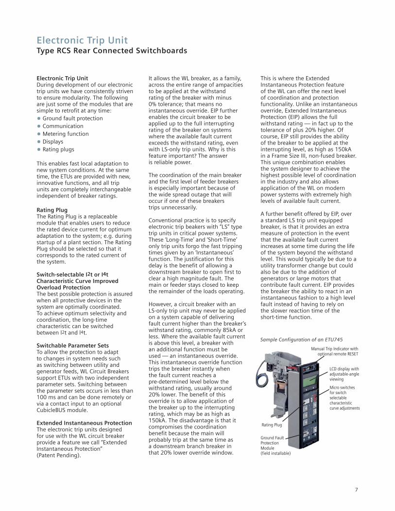
Sample Configuration of an ETU745
Micro switches for switch selectable characteristic curve adjustments
Rating Plug
LCD display with adjustable-angle viewing
Ground Fault ProtectionModule (field installable)
Manual Trip Indicator withoptional remote RESET
Electronic Trip UnitType RCS Rear Connected Switchboards
8
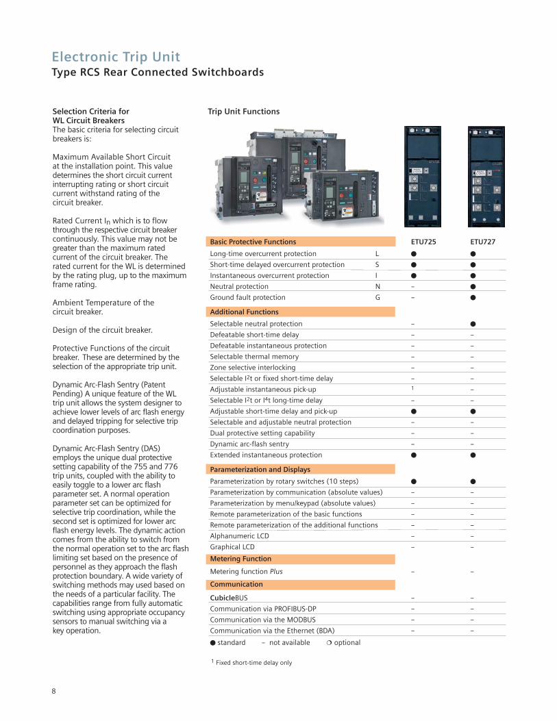
Selection Criteria forWL Circuit BreakersThe basic criteria for selecting circuitbreakers is:
Maximum Available Short Circuit at the installation point. This valuedetermines the short circuit currentinterrupting rating or short circuit current withstand rating of the circuit breaker.
Rated Current In which is to flowthrough the respective circuit breakercontinuously. This value may not begreater than the maximum rated current of the circuit breaker. The rated current for the WL is determinedby the rating plug, up to the maximumframe rating.
Ambient Temperature of the circuit breaker.
Design of the circuit breaker.
Protective Functions of the circuit breaker. These are determined by theselection of the appropriate trip unit.
Dynamic Arc-Flash Sentry (PatentPending) A unique feature of the WLtrip unit allows the system designer toachieve lower levels of arc flash energyand delayed tripping for selective tripcoordination purposes.
Dynamic Arc-Flash Sentry (DAS)employs the unique dual protective setting capability of the 755 and 776trip units, coupled with the ability toeasily toggle to a lower arc flash parameter set. A normal operationparameter set can be optimized forselective trip coordination, while thesecond set is optimized for lower arcflash energy levels. The dynamic actioncomes from the ability to switch fromthe normal operation set to the arc flashlimiting set based on the presence ofpersonnel as they approach the flashprotection boundary. A wide variety ofswitching methods may used based onthe needs of a particular facility. Thecapabilities range from fully automaticswitching using appropriate occupancysensors to manual switching via a key operation.
Basic Protective Functions ETU725 ETU727
Long-time overcurrent protection L � �
Short-time delayed overcurrent protection S � �
Instantaneous overcurrent protection I � �
Neutral protection N -- �
Ground fault protection G -- �
Additional Functions
Selectable neutral protection -- �
Defeatable short-time delay -- --
Defeatable instantaneous protection -- --
Selectable thermal memory -- --
Zone selective interlocking -- --
Selectable I2t or fixed short-time delay -- --
Adjustable instantaneous pick-up 1 --
Selectable I2t or I4t long-time delay -- --
Adjustable short-time delay and pick-up � �
Selectable and adjustable neutral protection -- --
Dual protective setting capability -- --
Dynamic arc-flash sentry -- --
Extended instantaneous protection � �
Parameterization and Displays
Parameterization by rotary switches (10 steps) � �
Parameterization by communication (absolute values) -- --
Parameterization by menu/keypad (absolute values) -- --
Remote parameterization of the basic functions -- --
Remote parameterization of the additional functions -- --
Alphanumeric LCD -- --
Graphical LCD -- --
Metering Function
Metering function Plus -- --
Communication
CubicleBUS -- --
Communication via PROFIBUS-DP -- --
Communication via the MODBUS -- --
Communication via the Ethernet (BDA) -- --
� standard -- not available � optional
1 Fixed short-time delay only
Trip Unit Functions
Electronic Trip UnitType RCS Rear Connected Switchboards
9
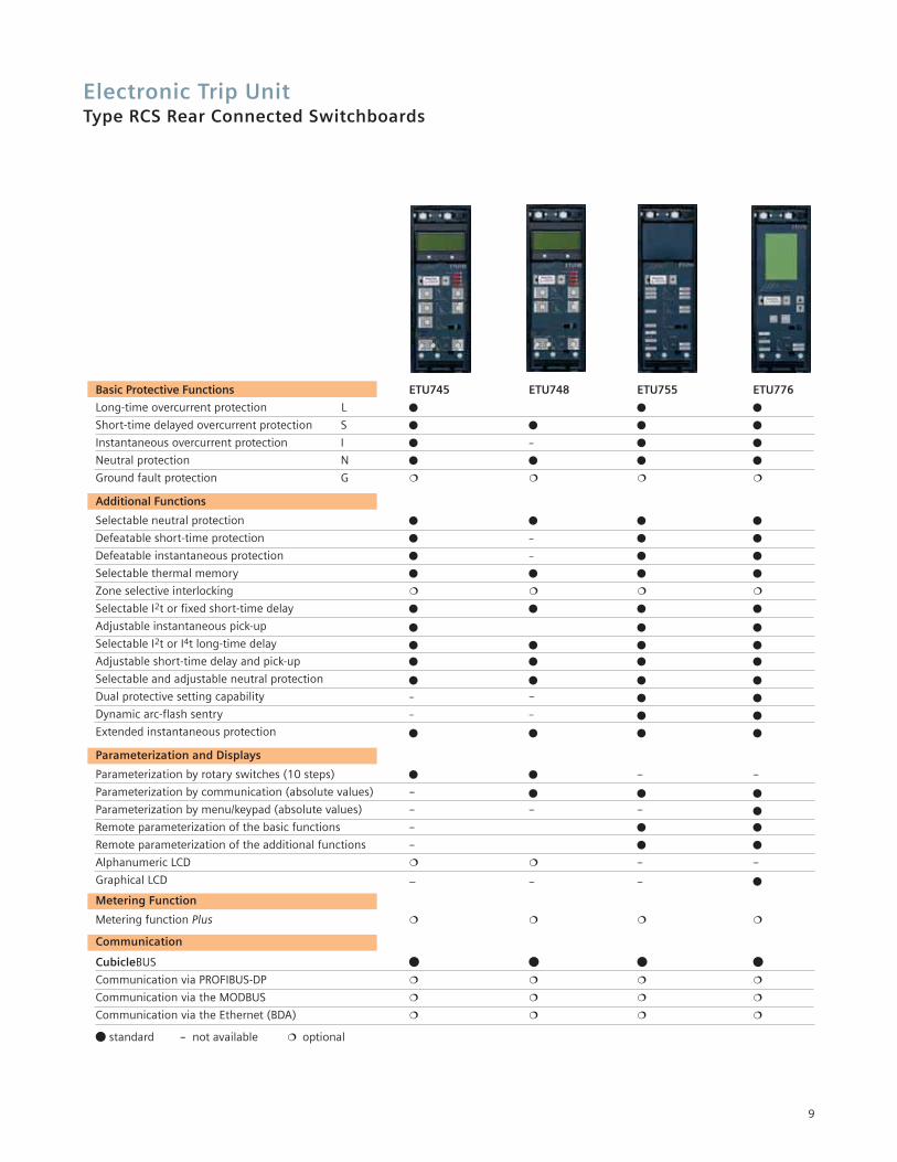
Basic Protective Functions ETU745 ETU748 ETU755 ETU776
Long-time overcurrent protection L � � �
Short-time delayed overcurrent protection S � � � �
Instantaneous overcurrent protection I � -- � �
Neutral protection N � � � �
Ground fault protection G
Additional Functions
Selectable neutral protection � � � �
Defeatable short-time protection � -- � �
Defeatable instantaneous protection � -- � �
Selectable thermal memory � � � �
Zone selective interlocking
Selectable I2t or fixed short-time delay � � � �
Adjustable instantaneous pick-up � � �
Selectable I2t or I4t long-time delay � � � �
Adjustable short-time delay and pick-up � � � �
Selectable and adjustable neutral protection � � � �
Dual protective setting capability -- -- � �
Dynamic arc-flash sentry -- -- � �
Extended instantaneous protection � � � �
Parameterization and Displays
Parameterization by rotary switches (10 steps) � � -- --
Parameterization by communication (absolute values) -- � � �
Parameterization by menu/keypad (absolute values) -- -- -- �
Remote parameterization of the basic functions -- � �
Remote parameterization of the additional functions -- � �
Alphanumeric LCD -- --
Graphical LCD – -- -- �
Metering Function
Metering function Plus
Communication
CubicleBUS � � � �
Communication via PROFIBUS-DP
Communication via the MODBUS
Communication via the Ethernet (BDA)
� standard -- not available optional
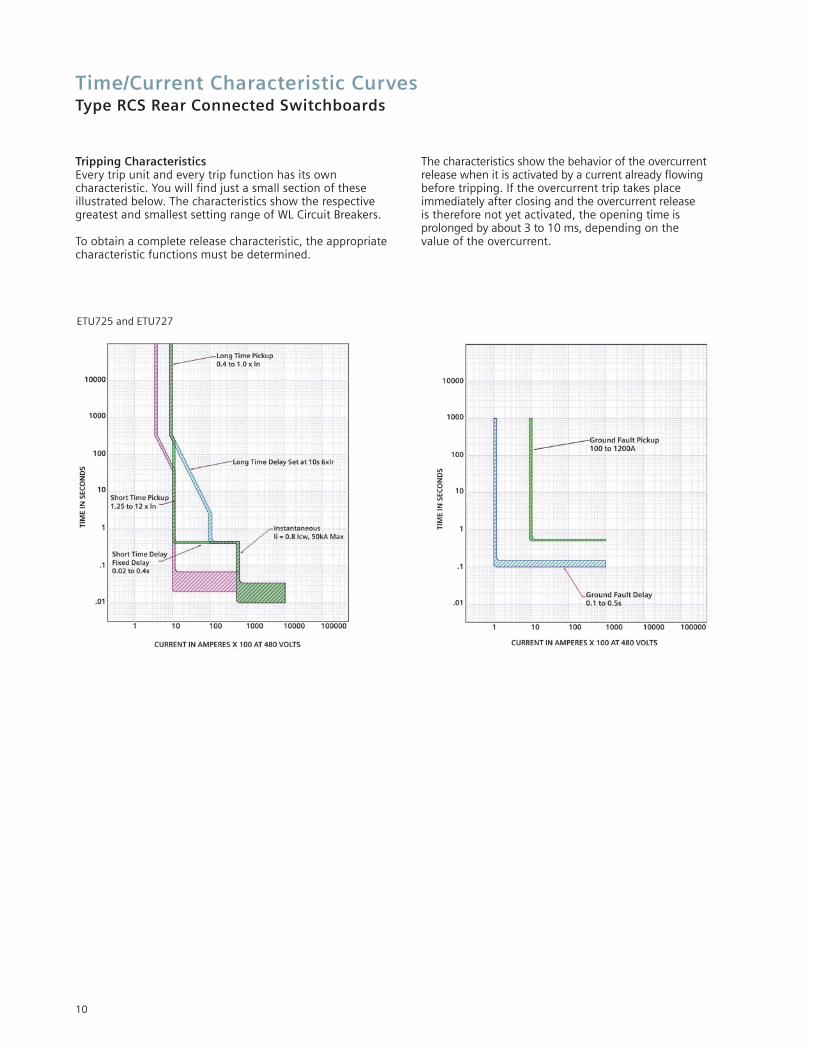
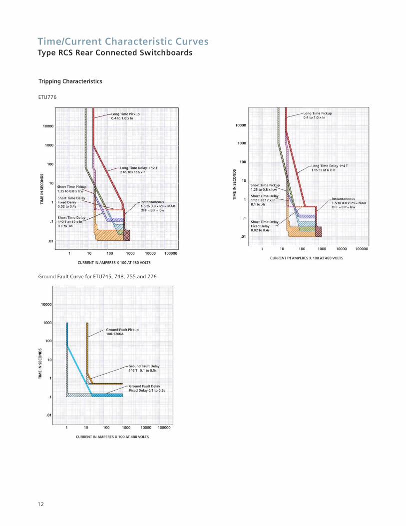
Time/Current Characteristic CurvesType RCS Rear Connected Switchboards
Tripping CharacteristicsEvery trip unit and every trip function has its own characteristic. You will find just a small section of these illustrated below. The characteristics show the respectivegreatest and smallest setting range of WL Circuit Breakers.
To obtain a complete release characteristic, the appropriate characteristic functions must be determined.
The characteristics show the behavior of the overcurrentrelease when it is activated by a current already flowingbefore tripping. If the overcurrent trip takes place immediately after closing and the overcurrent release is therefore not yet activated, the opening time is prolonged by about 3 to 10 ms, depending on the value of the overcurrent.
10
ETU725 and ETU727
Time/Current Characteristic CurvesType RCS Rear Connected Switchboards
11
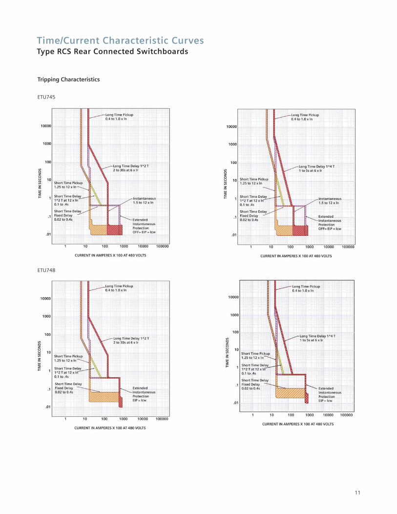
Tripping Characteristics
ETU745
ETU748
Time/Current Characteristic CurvesType RCS Rear Connected Switchboards
12
Tripping Characteristics
ETU776
Ground Fault Curve for ETU745, 748, 755 and 776
13
Frame Size 1800 1200S H L S H L
240V 65 85 100 65 85 100480V 65 85 100 65 85 100600V 65 65 65 65 65 65
0.5 s 65 65 65 65 65 65240-480V 65 85 100 65 85 100600V 65 65 65 65 65 65
65 65 65 65 65 65200A to 800A 200A to 1200A
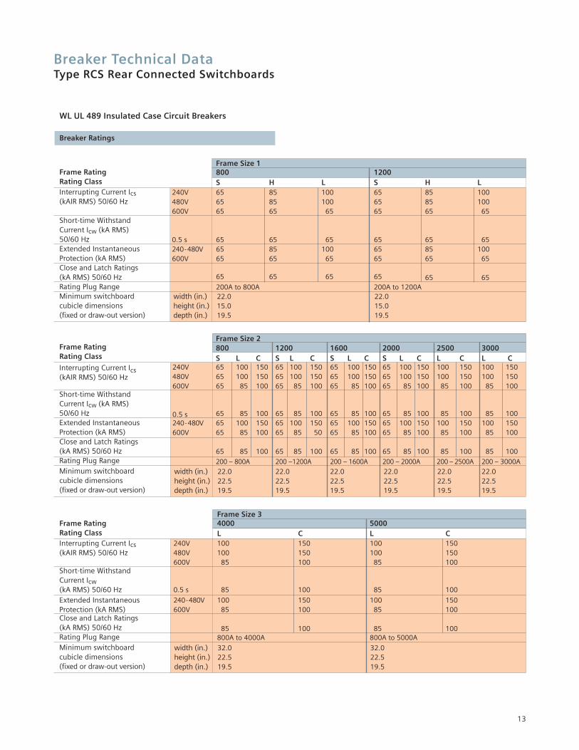
WL UL 489 Insulated Case Circuit Breakers
Breaker Ratings
Frame RatingRating ClassInterrupting Current Ics(kAIR RMS) 50/60 Hz
Short-time Withstand Current Icw (kA RMS)50/60 HzExtended Instantaneous Protection (kA RMS)Close and Latch Ratings(kA RMS) 50/60 HzRating Plug RangeMinimum switchboardcubicle dimensions(fixed or draw-out version)
width (in.) 22.0 22.0height (in.) 15.0 15.0depth (in.) 19.5 19.5
Frame Size 2800 1200 1600 2000 2500 3000S L C S L C S L C S L C L C L C
240V 65 100 150 65 100 150 65 100 150 65 100 150 100 150 100 150480V 65 100 150 65 100 150 65 100 150 65 100 150 100 150 100 150600V 65 85 100 65 85 100 65 85 100 65 85 100 85 100 85 100
0.5 s 65 85 100 65 85 100 65 85 100 65 85 100 85 100 85 100240-480V 65 100 150 65 100 150 65 100 150 65 100 150 100 150 100 150600V 65 85 100 65 85 50 65 85 100 65 85 100 85 100 85 100
65 85 100 65 85 100 65 85 100 65 85 100 85 100 85 100
200 – 800A 200 –1200A 200 – 1600A 200 – 2000A 200 – 2500A 200 – 3000A
Frame RatingRating Class
Interrupting Current Ics(kAIR RMS) 50/60 Hz
Short-time Withstand Current Icw (kA RMS)50/60 HzExtended Instantaneous Protection (kA RMS)Close and Latch Ratings(kA RMS) 50/60 HzRating Plug RangeMinimum switchboardcubicle dimensions(fixed or draw-out version)
width (in.) 22.0 22.0 22.0 22.0 22.0 22.0height (in.) 22.5 22.5 22.5 22.5 22.5 22.5depth (in.) 19.5 19.5 19.5 19.5 19.5 19.5
Frame Size 34000 5000L C L C
240V 100 150 100 150480V 100 150 100 150600V 85 100 85 100
0.5 s 85 100 85 100
240-480V 100 150 100 150600V 85 100 85 100
85 100 85 100800A to 4000A 800A to 5000A
Frame RatingRating ClassInterrupting Current Ics(kAIR RMS) 50/60 Hz
Short-time Withstand Current Icw(kA RMS) 50/60 HzExtended InstantaneousProtection (kA RMS)Close and Latch Ratings(kA RMS) 50/60 HzRating Plug RangeMinimum switchboardcubicle dimensions(fixed or draw-out version)
width (in.) 32.0 32.0height (in.) 22.5 22.5depth (in.) 19.5 19.5
Breaker Technical DataType RCS Rear Connected Switchboards
14
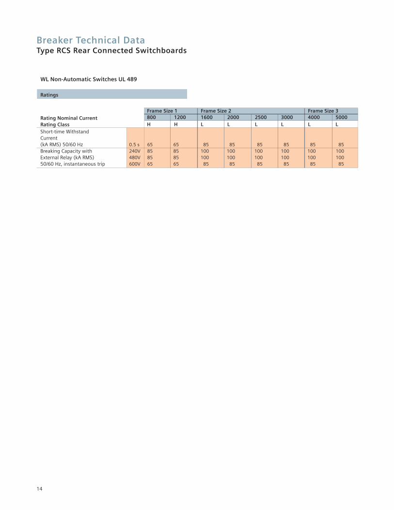
Frame Size 1 Frame Size 2 Frame Size 3800 1200 1600 2000 2500 3000 4000 5000H H L L L L L L
0.5 s 65 65 85 85 85 85 85 85240V 85 85 100 100 100 100 100 100480V 85 85 100 100 100 100 100 100600V 65 65 85 85 85 85 85 85
Breaker Technical DataType RCS Rear Connected Switchboards
WL Non-Automatic Switches UL 489
Ratings
Rating Nominal CurrentRating ClassShort-time Withstand Current (kA RMS) 50/60 HzBreaking Capacity withExternal Relay (kA RMS)50/60 Hz, instantaneous trip
Breaker Technical DataType RCS Rear Connected Switchboards
15
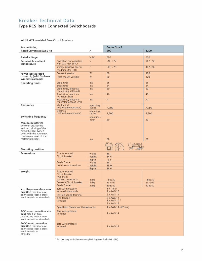
Frame Size 1A 800 1200
V AC 600 600C -25 / +70 25 / +70
C -40 / +70 40 / +70
W 80 180
W 60 120
ms 35 35ms 34 34ms 50 50
ms 40 40
ms 73 73
operatingcycles 7,500 7,500operatingcycles 7,500 7,500
operations/hour 60 60
ms 80 80
width 18.1height 14.6depth 9.5width 18.1height 15.0depth 18.6
lb/kg 86 / 39 86 / 39lb/kg 137 / 62 137 / 62lb/kg 108 / 49 108 / 49
1 x 14 or2 x AWG 162 x AWG 142 x AWG 141 x AWG 10 1
2 x AWG 16
1 x AWG 14, 40” long
1 x AWG 14
1 x AWG 14
1 For use only with Siemens supplied ring terminals (WL10RL)
Frame RatingRated Current at 50/60 Hz
Rated voltageOperation (for operationwith LCD max 55ºC)Storage (observe specialconditions for LCD)Drawout version
Fixed mount version
Make-timeBreak-timeMake-time, electrical(via closing solenoid)Break-time, electrical(via shunt trip)Break-time, electrical(via instantaneous UVR)
Endurance Mechanical (without maintenance)Electrical (without maintenance)
Switching frequency
Minimum intervalbetween breaker trip and next closing of the circuit breaker (when used with the automatic mechanical reset of the reclosing lockout)
Mounting position
Dimensions Fixed-mounted Circuit Breaker
Guide Frame(for draw-out version)
Weight Fixed-mounted Circuit Breaker(w/o main busbar connectors)Drawout Circuit BreakerGuide FrameBare wire pressureterminal (standard)
Tension spring terminalRing tongue terminal
Pigtail leads (fixed mount breaker only)
Bare wire pressureterminal
Bare wire pressureterminal
Permissible ambient temperature
Power loss at rated current In (with 3-phasesymmetrical load)
Operating times
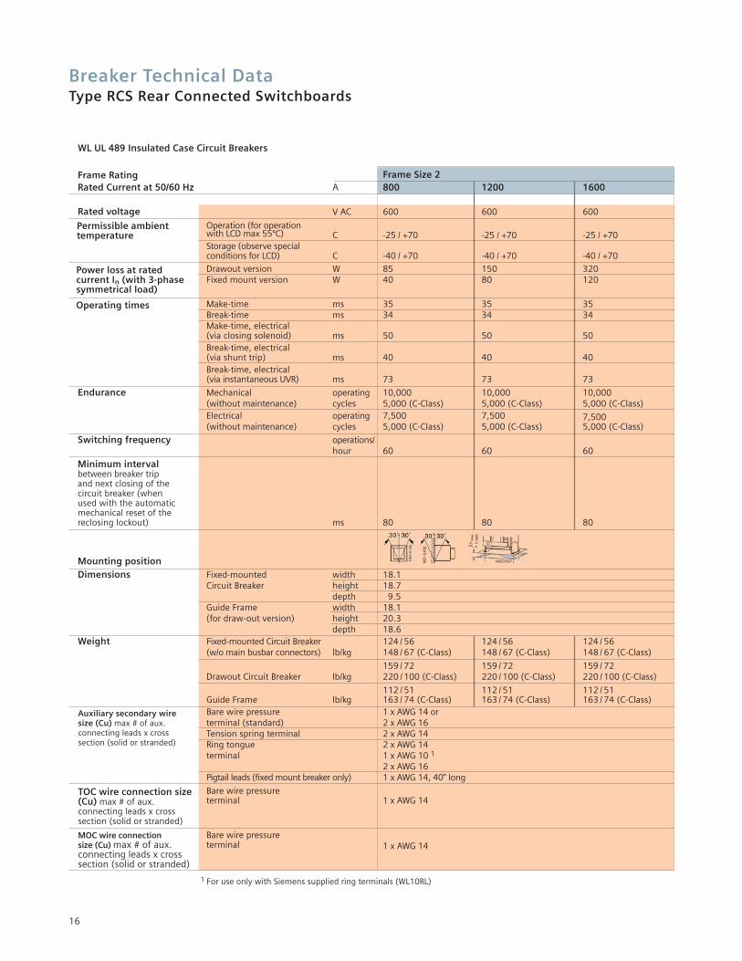
WL UL 489 Insulated Case Circuit Breakers
Auxiliary secondary wire size (Cu) max # of aux. connecting leads x cross section (solid or stranded)
TOC wire connection size(Cu) max # of aux. connecting leads x cross section (solid or stranded)
MOC wire connection size (Cu) max # of aux. connecting leads x crosssection (solid or stranded)
16
WL UL 489 Insulated Case Circuit Breakers
Frame Size 2A 800 1200 1600
V AC 600 600 600
C -25 / +70 -25 / +70 -25 / +70
C -40 / +70 -40 / +70 -40 / +70
W 85 150 320W 40 80 120
ms 35 35 35ms 34 34 34
ms 50 50 50
ms 40 40 40
ms 73 73 73
operating 10,000 10,000 10,000cycles 5,000 (C-Class) 5,000 (C-Class) 5,000 (C-Class)operating 7,500 7,500 7,500cycles 5,000 (C-Class) 5,000 (C-Class) 5,000 (C-Class)
operations/hour 60 60 60
ms 80 80 80
width 18.1height 18.7depth 9.5width 18.1height 20.3depth 18.6
124 / 56 124 / 56 124 / 56lb/kg 148 / 67 (C-Class) 148 / 67 (C-Class) 148 / 67 (C-Class)
159 / 72 159 / 72 159 / 72lb/kg 220 / 100 (C-Class) 220 / 100 (C-Class) 220 / 100 (C-Class)
112 / 51 112 / 51 112 / 51lb/kg 163 / 74 (C-Class) 163 / 74 (C-Class) 163 / 74 (C-Class)
1 x AWG 14 or2 x AWG 162 x AWG 142 x AWG 141 x AWG 10 1
2 x AWG 161 x AWG 14, 40” long
1 x AWG 14
1 x AWG 14
1 For use only with Siemens supplied ring terminals (WL10RL)
Frame RatingRated Current at 50/60 Hz
Rated voltageOperation (for operation with LCD max 55ºC)Storage (observe specialconditions for LCD)
Drawout versionFixed mount version
Make-timeBreak-timeMake-time, electrical(via closing solenoid)Break-time, electrical(via shunt trip)Break-time, electrical(via instantaneous UVR)
Endurance Mechanical (without maintenance)Electrical (without maintenance)
Switching frequency
Minimum intervalbetween breaker trip and next closing of the circuit breaker (when used with the automatic mechanical reset of the reclosing lockout)
Mounting positionDimensions Fixed-mounted
Circuit Breaker
Guide Frame(for draw-out version)
Weight Fixed-mounted Circuit Breaker(w/o main busbar connectors)
Drawout Circuit Breaker
Guide FrameBare wire pressureterminal (standard)Tension spring terminalRing tongue terminal
Pigtail leads (fixed mount breaker only)
Bare wire pressureterminal
Bare wire pressureterminal
Permissible ambient temperature
Power loss at rated current In (with 3-phasesymmetrical load)
Operating times
Auxiliary secondary wiresize (Cu) max # of aux.connecting leads x cross section (solid or stranded)
TOC wire connection size(Cu) max # of aux. connecting leads x cross section (solid or stranded)
MOC wire connectionsize (Cu) max # of aux.connecting leads x crosssection (solid or stranded)
Breaker Technical DataType RCS Rear Connected Switchboards

17
Frame Size 2A 2000 2500 3000
V AC 600 600 600
C -25 / +70 -25 / +70 -25 / +70
C -40 / +70 -40 / +70 -40 / +70
W 500 680 1000W 230 320 450
ms 35 35 35ms 34 34 34
ms 50 50 50
ms 40 40 40
ms 73 73 73
operating 10,000 10,000 10,000cycles 5,000 (C-Class) 5,000 (C-Class) 5,000 (C-Class)operatingcycles 4,000 4,000 4,000
operations/hour 60 60 60
ms 80 80 80
width 18.1height 18.7depth 9.5width 18.1height 20.3depth 18.6
130 / 59 141 / 64 141 / 64lb/kg 148 / 67 (C-Class) 148 / 67 (C-Class) 148 / 67 (C-Class)
177 / 80 209 / 95 209 / 95lb/kg 220 / 100 (C-Class) 220 / 100 (C-Class) 220 / 100 (C-Class)
128 / 58 152 / 69 152 / 69lb/kg 163 / 74 (C-Class) 163 / 74 (C-Class) 163 / 74 (C-Class)
1 x AWG 14 or2 x AWG 162 x AWG 142 x AWG 141 x AWG 10 1
2 x AWG 161 x AWG 14, 40” long
1 x AWG 14
1 x AWG 14
1 For use only with Siemens supplied ring terminals (WL10RL)
Frame RatingRated Current at 50/60 Hz
Rated voltageOperation (for operation with LCD max 55ºC)Storage (observe specialconditions for LCD)
Drawout versionFixed mount version
Make-timeBreak-timeMake-time, electrical(via closing solenoid)Break-time, electrical(via shunt trip)Break-time, electrical(via instantaneous UVR)
Endurance Mechanical (without maintenance)Electrical (without maintenance)
Switching frequency
Minimum intervalbetween breaker trip andnext closing of the circuit breaker (when used with the automatic mechanical reset of the reclosing lockout)
Mounting position Dimensions Fixed-mounted
Circuit Breaker
Guide Frame(for draw-out version)
Weight Fixed-mounted Circuit Breaker(w/o main busbar connectors)
Drawout Circuit Breaker
Guide FrameBare wire pressureterminal (standard)Tension spring terminalRing tongue terminal
Pigtail leads (fixed mount breaker only)
Bare wire pressureterminal
Bare wire pressureterminal
Permissible ambient temperature
Power loss at rated current In (with 3-phase symmetrical load)
Operating times
Auxiliary secondary wire size (Cu) max # of aux.connecting leads x crosssection (solid or stranded)
TOC wire connection size (Cu) max # of aux. connecting leads x cross section (solid or stranded)
MOC wire connectionsize (Cu) max # of aux.connecting leads x crosssection (solid or stranded)
Breaker Technical DataType RCS Rear Connected Switchboards
18
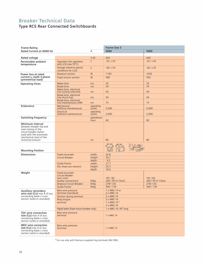
Frame Size 3A 4000 5000
V AC 600 600C -25 / +70 -25 / +70
C -40 / +70 -40 / +70
W 1100 1650
W 580 950
ms 35 35ms 34 34
ms 50 50
ms 40 40
ms 73 73operatingcycles 5,000 5,000operatingcycles 2,000 2,000
operations/hour 60 60
ms 80 80
width 26.8height 20.7depth 9.5width 27.7height 20.3depth 18.6
181 / 82 181 / 82lb/kg 200 / 90 (C-Class) 200 / 90 (C-Class)lb/kg 278 / 126 278 / 126lb/kg 306 / 139 306 / 139
1 x AWG 14 or2 x AWG 162 x AWG 142 x AWG 141 x AWG 10 1
2 x AWG 161 x AWG 14, 40” long
1 x AWG 14
1 x AWG 14
1 For use only with Siemens supplied ring terminals (WL10RL)
Frame RatingRated Current at 50/60 Hz
Rated voltageOperation (for operation with LCD max 55ºC)Storage (observe specialconditions for LCD)Drawout version
Fixed mount version
Make-timeBreak-timeMake-time, electrical(via closing solenoid)Break-time, electrical(via shunt trip)Break-time, electrical(via instantaneous UVR)
Endurance Mechanical (without maintenance)Electrical (without maintenance)
Switching frequency
Minimum interval between breaker trip andnext closing of the circuit breaker (when used with the automatic mechanical reset of the reclosing lockout)
Mounting Position
Dimensions Fixed-mounted Circuit Breaker
Guide Frame(for draw-out version)
Weight Fixed-mounted Circuit Breaker(w/o main busbar connectors)Drawout Circuit BreakerGuide Frame
Bare wire pressureterminal (standard)Tension spring terminalRing tongue terminal
Pigtail leads (fixed mount breaker only)
Bare wire pressureterminal
Bare wire pressureterminal
Permissible ambient temperature
Power loss at rated current In (with 3-phasesymmetrical load)
Operating times
Auxiliary secondary wire size (Cu) max # of aux.connecting leads x cross section (solid or stranded)
TOC wire connection size (Cu) max # of aux. connecting leads x cross section (solid or stranded)
MOC wire connection size (Cu) max # of aux. connecting leads x crosssection (solid or stranded)
Breaker Technical DataType RCS Rear Connected Switchboards
19
Frame Size 2800 1600 2000 3200N S H L F N S H L F S H L F S H L
254V AC 50 65 85 100 200 50 65 85 100 200 65 85 100 200 65 85 100508V AC 50 65 85 100 200 50 65 85 100 200 65 85 100 200 65 85 100635V AC 50 65 65 85 200 50 65 65 85 200 65 65 85 200 65 65 85
0.5 s 50 65 65 85 — 50 65 65 85 — 65 65 85 — 65 65 85
285
508V AC 50 65 95 100 — 50 65 85 100 — 65 85 100 — 65 85 100635V AC 50 65 65 85 — 50 65 65 85 — 65 65 85 — 65 65 85
50 65 65 85 65 50 65 65 85 65 65 65 85 65 65 65 85200 – 800A 200 –1600A 200 – 2000A 200 – 3200A
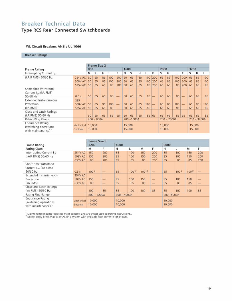
WL Circuit Breakers ANSI / UL 1066
Breaker Ratings
Frame RatingInterrupting Current Ics
(kAIR RMS) 50/60 Hz
Short-time Withstand Current Icw (kA RMS) 50/60 HzExtended Instantaneous Protection(kA RMS)Close and Latch Ratings(kA RMS) 50/60 HzRating Plug RangeEndurance Rating (switching operations with maintenance) 1
Frame Size 33200 4000 5000M F H L M F H L M F
254V AC 150 200 85 100 150 200 85 100 150 200508V AC 150 200 85 100 150 200 85 100 150 200635V AC 85 200 85 85 85 200 85 85 85 200
0.5 s 100 2 — 85 100 2 100 2 — 85 100 2 100 2 —254V AC508V AC 150 — 85 100 150 — 85 100 150 —635V AC 85 — 85 85 85 — 85 85 85 —
100 85 85 100 100 85 85 100 100 85
800 – 3200A 800 – 4000A 800 –5000A
Frame RatingRating ClassInterrupting Current Ics
(kAIR RMS) 50/60 Hz
Short-time Withstand Current Icw (kA RMS)50/60 HzExtended Instantaneous Protection(kA RMS)Close and Latch Ratings(kA RMS) 50/60 HzRating Plug RangeEndurance Rating (switching operations with maintenance) 1
1 Maintenance means: replacing main contacts and arc chutes (see operating instructions).2 Do not apply breaker at 635V AC on a system with available fault current > 85kA RMS.
Mechanical 15,000 15,000 15,000 15,000Electrical 15,000 15,000 15,000 15,000
Mechanical 10,000 10,000 10,000Electrical 10,000 10,000 10,000
Breaker Technical DataType RCS Rear Connected Switchboards
20
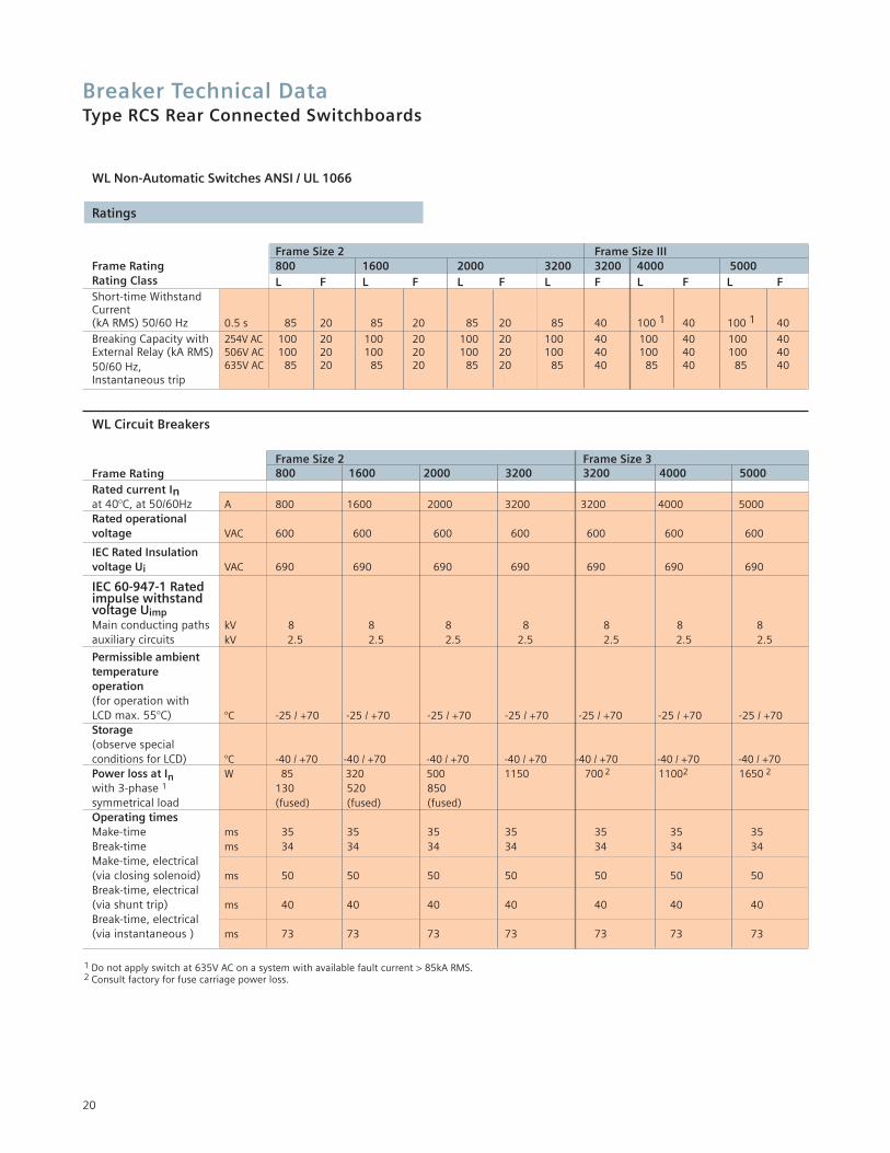
WL Non-Automatic Switches ANSI / UL 1066
Ratings
Frame Size 2 Frame Size IIIFrame Rating 800 1600 2000 3200 3200 4000 5000Rating Class L F L F L F L F L F L F Short-time Withstand Current (kA RMS) 50/60 Hz 0.5 s 85 20 85 20 85 20 85 40 100 1 40 100 1 40
Breaking Capacity with 254V AC 100 20 100 20 100 20 100 40 100 40 100 40External Relay (kA RMS) 506V AC 100 20 100 20 100 20 100 40 100 40 100 4050/60 Hz, 635V AC 85 20 85 20 85 20 85 40 85 40 85 40Instantaneous trip
WL Circuit Breakers
Frame Size 2 Frame Size 3Frame Rating 800 1600 2000 3200 3200 4000 5000Rated current Inat 40°C, at 50/60Hz A 800 1600 2000 3200 3200 4000 5000Rated operational voltage VAC 600 600 600 600 600 600 600
IEC Rated Insulation voltage Ui VAC 690 690 690 690 690 690 690
IEC 60-947-1 Ratedimpulse withstandvoltage UimpMain conducting paths kV 8 8 8 8 8 8 8auxiliary circuits kV 2.5 2.5 2.5 2.5 2.5 2.5 2.5
Permissible ambient temperatureoperation(for operation with LCD max. 55°C) °C -25 / +70 -25 / +70 -25 / +70 -25 / +70 -25 / +70 -25 / +70 -25 / +70Storage (observe special conditions for LCD) °C -40 / +70 -40 / +70 -40 / +70 -40 / +70 -40 / +70 -40 / +70 -40 / +70Power loss at In W 85 320 500 1150 700 2 11002 1650 2
with 3-phase 1 130 520 850symmetrical load (fused) (fused) (fused)Operating timesMake-time ms 35 35 35 35 35 35 35Break-time ms 34 34 34 34 34 34 34Make-time, electrical (via closing solenoid) ms 50 50 50 50 50 50 50Break-time, electrical(via shunt trip) ms 40 40 40 40 40 40 40Break-time, electrical(via instantaneous ) ms 73 73 73 73 73 73 73
1 Do not apply switch at 635V AC on a system with available fault current > 85kA RMS.2 Consult factory for fuse carriage power loss.
Breaker Technical DataType RCS Rear Connected Switchboards
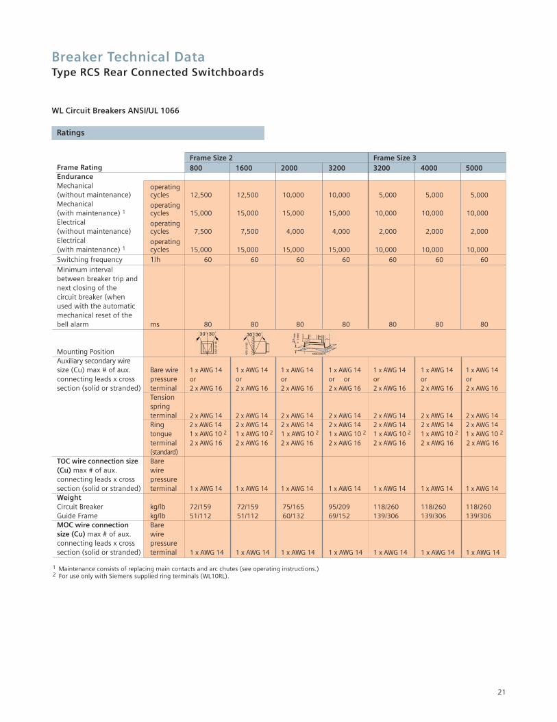
21
Frame Size 2 Frame Size 3Frame Rating 800 1600 2000 3200 3200 4000 5000EnduranceMechanical operating(without maintenance) cycles 12,500 12,500 10,000 10,000 5,000 5,000 5,000Mechanical operating(with maintenance) 1 cycles 15,000 15,000 15,000 15,000 10,000 10,000 10,000Electrical operating(without maintenance) cycles 7,500 7,500 4,000 4,000 2,000 2,000 2,000Electrical operating(with maintenance) 1 cycles 15,000 15,000 15,000 15,000 10,000 10,000 10,000
Switching frequency 1/h 60 60 60 60 60 60 60
Minimum interval between breaker trip and next closing of the circuit breaker (when used with the automatic mechanical reset of the bell alarm ms 80 80 80 80 80 80 80
Mounting Position Auxiliary secondary wire size (Cu) max # of aux. Bare wire 1 x AWG 14 1 x AWG 14 1 x AWG 14 1 x AWG 14 1 x AWG 14 1 x AWG 14 1 x AWG 14connecting leads x cross pressure or or or or or or or orsection (solid or stranded) terminal 2 x AWG 16 2 x AWG 16 2 x AWG 16 2 x AWG 16 2 x AWG 16 2 x AWG 16 2 x AWG 16
Tensionspringterminal 2 x AWG 14 2 x AWG 14 2 x AWG 14 2 x AWG 14 2 x AWG 14 2 x AWG 14 2 x AWG 14Ring 2 x AWG 14 2 x AWG 14 2 x AWG 14 2 x AWG 14 2 x AWG 14 2 x AWG 14 2 x AWG 14tongue 1 x AWG 10 2 1 x AWG 10 2 1 x AWG 10 2 1 x AWG 10 2 1 x AWG 10 2 1 x AWG 10 2 1 x AWG 10 2
terminal 2 x AWG 16 2 x AWG 16 2 x AWG 16 2 x AWG 16 2 x AWG 16 2 x AWG 16 2 x AWG 16(standard)
TOC wire connection size Bare(Cu) max # of aux. wireconnecting leads x cross pressuresection (solid or stranded) terminal 1 x AWG 14 1 x AWG 14 1 x AWG 14 1 x AWG 14 1 x AWG 14 1 x AWG 14 1 x AWG 14WeightCircuit Breaker kg/lb 72/159 72/159 75/165 95/209 118/260 118/260 118/260Guide Frame kg/lb 51/112 51/112 60/132 69/152 139/306 139/306 139/306MOC wire connection Baresize (Cu) max # of aux. wireconnecting leads x cross pressuresection (solid or stranded) terminal 1 x AWG 14 1 x AWG 14 1 x AWG 14 1 x AWG 14 1 x AWG 14 1 x AWG 14 1 x AWG 14
1 Maintenance consists of replacing main contacts and arc chutes (see operating instructions.) 2 For use only with Siemens supplied ring terminals (WL10RL).
WL Circuit Breakers ANSI/UL 1066
Ratings
Breaker Technical DataType RCS Rear Connected Switchboards
22
WL Circuit Breaker Accessory Ratings
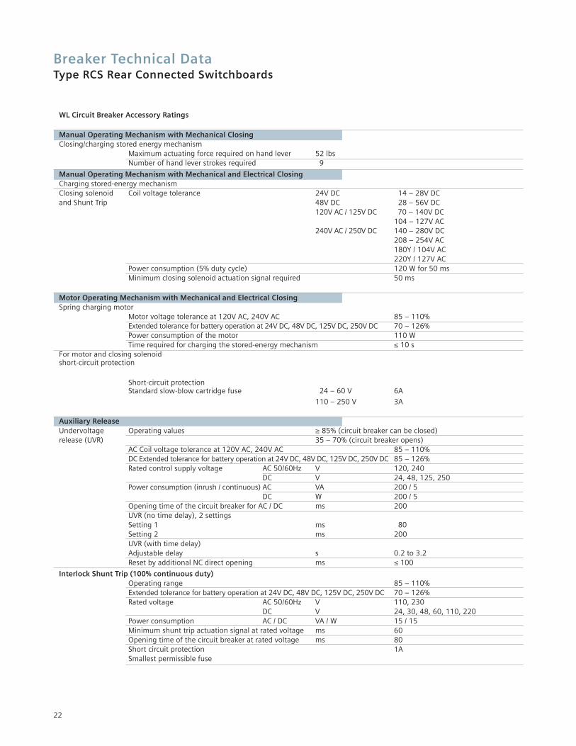
Manual Operating Mechanism with Mechanical ClosingClosing/charging stored energy mechanism
Maximum actuating force required on hand lever 52 lbsNumber of hand lever strokes required 9
Manual Operating Mechanism with Mechanical and Electrical ClosingCharging stored-energy mechanismClosing solenoid Coil voltage tolerance 24V DC 14 – 28V DCand Shunt Trip 48V DC 28 – 56V DC
120V AC / 125V DC 70 – 140V DC104 – 127V AC
240V AC / 250V DC 140 – 280V DC208 – 254V AC180Y / 104V AC220Y / 127V AC
Power consumption (5% duty cycle) 120 W for 50 msMinimum closing solenoid actuation signal required 50 ms
Motor Operating Mechanism with Mechanical and Electrical ClosingSpring charging motor
Motor voltage tolerance at 120V AC, 240V AC 85 – 110%Extended tolerance for battery operation at 24V DC, 48V DC, 125V DC, 250V DC 70 – 126%Power consumption of the motor 110 WTime required for charging the stored-energy mechanism ≤ 10 s
For motor and closing solenoidshort-circuit protection
Short-circuit protectionStandard slow-blow cartridge fuse 24 – 60 V 6A
110 – 250 V 3A
Auxiliary ReleaseUndervoltage Operating values ≥ 85% (circuit breaker can be closed)release (UVR) 35 – 70% (circuit breaker opens)
AC Coil voltage tolerance at 120V AC, 240V AC 85 – 110%DC Extended tolerance for battery operation at 24V DC, 48V DC, 125V DC, 250V DC 85 – 126%Rated control supply voltage AC 50/60Hz V 120, 240
DC V 24, 48, 125, 250Power consumption (inrush / continuous) AC VA 200 / 5
DC W 200 / 5Opening time of the circuit breaker for AC / DC ms 200UVR (no time delay), 2 settingsSetting 1 ms 80Setting 2 ms 200UVR (with time delay)Adjustable delay s 0.2 to 3.2Reset by additional NC direct opening ms ≤ 100
Interlock Shunt Trip (100% continuous duty)Operating range 85 – 110%Extended tolerance for battery operation at 24V DC, 48V DC, 125V DC, 250V DC 70 – 126%Rated voltage AC 50/60Hz V 110, 230
DC V 24, 30, 48, 60, 110, 220Power consumption AC / DC VA / W 15 / 15Minimum shunt trip actuation signal at rated voltage ms 60Opening time of the circuit breaker at rated voltage ms 80Short circuit protection 1ASmallest permissible fuse
Breaker Technical DataType RCS Rear Connected Switchboards
23
WL Circuit Breaker Accessory Ratings
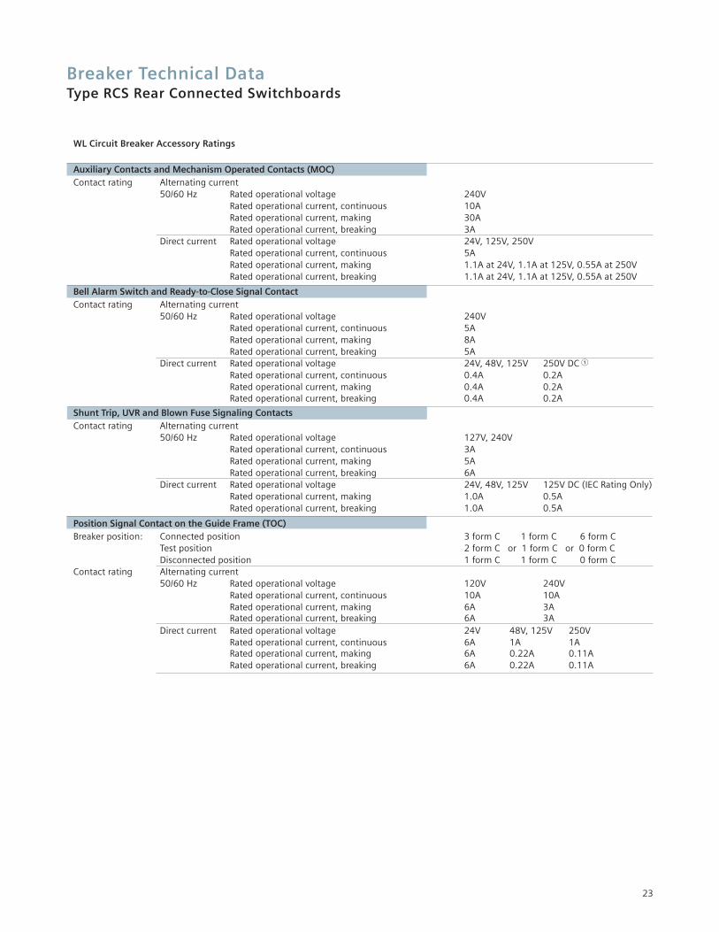
Auxiliary Contacts and Mechanism Operated Contacts (MOC)Contact rating Alternating current
50/60 Hz Rated operational voltage 240VRated operational current, continuous 10ARated operational current, making 30ARated operational current, breaking 3A
Direct current Rated operational voltage 24V, 125V, 250VRated operational current, continuous 5ARated operational current, making 1.1A at 24V, 1.1A at 125V, 0.55A at 250VRated operational current, breaking 1.1A at 24V, 1.1A at 125V, 0.55A at 250V
Bell Alarm Switch and Ready-to-Close Signal ContactContact rating Alternating current
50/60 Hz Rated operational voltage 240VRated operational current, continuous 5ARated operational current, making 8ARated operational current, breaking 5A
Direct current Rated operational voltage 24V, 48V, 125V 250V DC �
Rated operational current, continuous 0.4A 0.2ARated operational current, making 0.4A 0.2ARated operational current, breaking 0.4A 0.2A
Shunt Trip, UVR and Blown Fuse Signaling ContactsContact rating Alternating current
50/60 Hz Rated operational voltage 127V, 240VRated operational current, continuous 3ARated operational current, making 5A Rated operational current, breaking 6A
Direct current Rated operational voltage 24V, 48V, 125V 125V DC (IEC Rating Only)Rated operational current, making 1.0A 0.5ARated operational current, breaking 1.0A 0.5A
Position Signal Contact on the Guide Frame (TOC)Breaker position: Connected position 3 form C 1 form C 6 form C
Test position 2 form C or 1 form C or 0 form CDisconnected position 1 form C 1 form C 0 form C
Contact rating Alternating current50/60 Hz Rated operational voltage 120V 240V
Rated operational current, continuous 10A 10ARated operational current, making 6A 3ARated operational current, breaking 6A 3A
Direct current Rated operational voltage 24V 48V, 125V 250VRated operational current, continuous 6A 1A 1ARated operational current, making 6A 0.22A 0.11ARated operational current, breaking 6A 0.22A 0.11A
Breaker Technical DataType RCS Rear Connected Switchboards
24
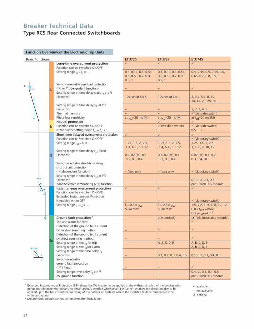
Basic Functions ETU725 ETU727 ETU745Long-time overcurrent protection � � �Function can be switched ON/OFF – – –Setting range IR = In x … 0.4, 0.45, 0.5, 0.55, 0.4, 0.45, 0.5, 0.55, 0.4, 0.45, 0.5, 0.55, 0.6,
0.6, 0.65, 0.7, 0.8, 0.6, 0.65, 0.7, 0.8, 0.65, 0.7, 0.8, 0.9, 10.9, 1 0.9, 1
Switch-selectable overload protection (I 2t or I 4t dependent function) – – �Setting range of time delay class tR at I 2t(seconds) 10s, set at 6 x Ir 10s, set at 6 x Ir 2, 3.5, 5.5, 8, 10,
14, 17, 21, 25, 30Setting range of time delay tR at I 4t(seconds) – – 1, 2, 3, 4, 5Thermal memory – – � (via slide switch)Phase loss sensitivity at tsd=20 ms (M) at tsd=20 ms (M) at tsd=20 ms (M)Neutral protection – � �Function can be switched ON/OFF – � (via slide switch) � (via slide switch)N-conductor setting range IN = In x … – 1 0.5 … 1
Short-time delayed overcurrent protection � � �Function can be switched ON/OFF – – � (via rotary switch)Setting range Isd = In x … 1.25, 1.5, 2, 2.5, 1.25, 1.5, 2, 2.5, 1.25, 1.5, 2, 2.5,
3, 4, 6, 8, 10, 12 3, 4, 6, 8, 10, 12 3, 4, 6, 8, 10, 12Setting range of time delay tsd, fixed(seconds) 0, 0.02 (M), 0.1, 0, 0.02 (M), 0.1, 0.02 (M), 0.1, 0.2,
0.2, 0.3, 0.4 0.2, 0.3, 0.4 0.3, 0.4, OFFSwitch-selectable short-time delay short-circuit protection (I 2t dependent function) – fixed only – fixed only � (via rotary switch)Setting range of time delay tsd at I 2t(seconds) – – 0.1, 0.2, 0.3, 0.4Zone Selective Interlocking (ZSI) function – – per CubicleBUS moduleInstantaneous overcurrent protection � � �Function can be switched ON/OFF, Extended Instantaneous Protectionis enabled when OFF – – � (via rotary switch)Setting range Ii = In x … Ii = 0.8 x Icw Ii = 0.8 x Icw 1.5, 2.2, 3, 4, 6, 8, 10, 12
50kA max 50kA max 0.8 x Icw = max,OFF= I cw=EIP 1
Ground fault protection 2 – � (standard) �(field installable module)Trip and alarm function – – �
Detection of the ground fault currentby residual summing method – � �
Detection of the ground fault current by direct summing method – – �
Setting range of the Ig for trip – A, B, C, D, E A, B, C, D, ESetting range of the Ig for alarm – – A, B, C, D, ESetting range of the time delay tg(seconds) – 0.1, 0.2, 0.3, 0.4, 0.5 0.1, 0.2, 0.3, 0.4, 0.5Switch-selectable ground fault protection (I 2t / fixed) – – �
Setting range time delay tg at I 2t – – 0.4, 0., 0.3, 0.4, 0.5ZSI ground function – – per CubicleBUS module
� available
– not available
� optional
L
N
S
I
G
1 Extended Instantaneous Protection (EIP) allows the WL breaker to be applied at the withstand rating of the breaker with minus 0% tolerance; that means no instantaneous override whatsoever. EIP further enables the circuit breaker to be applied up to the full instantaneous rating of the breaker on systems where the available fault current exceeds the withstand rating.
2 Ground Fault Module cannot be removed after installation.
In
Function Overview of the Electronic Trip Units
Breaker Technical DataType RCS Rear Connected Switchboards
25
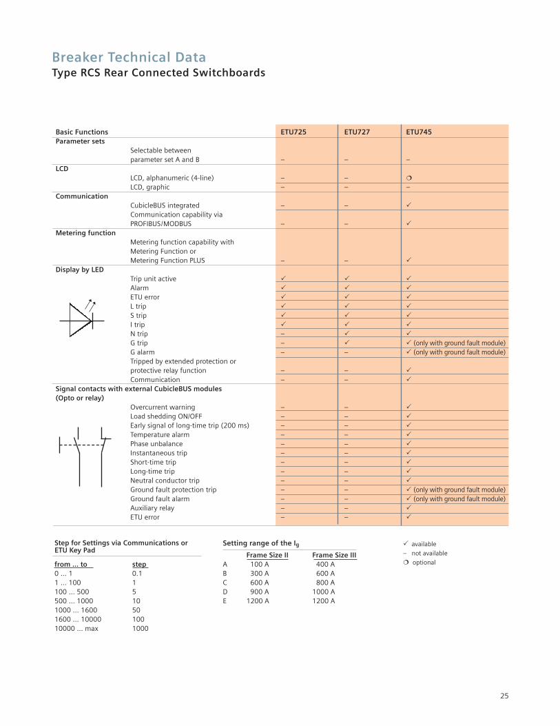
Basic Functions ETU725 ETU727 ETU745Parameter sets
Selectable between parameter set A and B – – –
LCDLCD, alphanumeric (4-line) – – �
LCD, graphic – – –Communication
CubicleBUS integrated – – �Communication capability via PROFIBUS/MODBUS – – �
Metering functionMetering function capability with Metering Function or Metering Function PLUS – – �
Display by LEDTrip unit active � � �Alarm � � �ETU error � � �L trip � � �S trip � � �I trip � � �N trip – � �G trip – � � (only with ground fault module)G alarm – – � (only with ground fault module)Tripped by extended protection or protective relay function – – �Communication – – �
Signal contacts with external CubicleBUS modules (Opto or relay)
Overcurrent warning – – �Load shedding ON/OFF – – �Early signal of long-time trip (200 ms) – – �Temperature alarm – – �Phase unbalance – – �Instantaneous trip – – �Short-time trip – – �Long-time trip – – �Neutral conductor trip – – �Ground fault protection trip – – � (only with ground fault module)Ground fault alarm – – � (only with ground fault module)Auxiliary relay – – �ETU error – – �
� available
– not available
� optionalfrom … to step0 … 1 0.11 … 100 1100 … 500 5500 … 1000 101000 … 1600 501600 … 10000 10010000 … max 1000
Step for Settings via Communications or ETU Key Pad
Setting range of the Ig
Frame Size II Frame Size IIIA 100 A 400 AB 300 A 600 AC 600 A 800 AD 900 A 1000 AE 1200 A 1200 A
Breaker Technical DataType RCS Rear Connected Switchboards
26
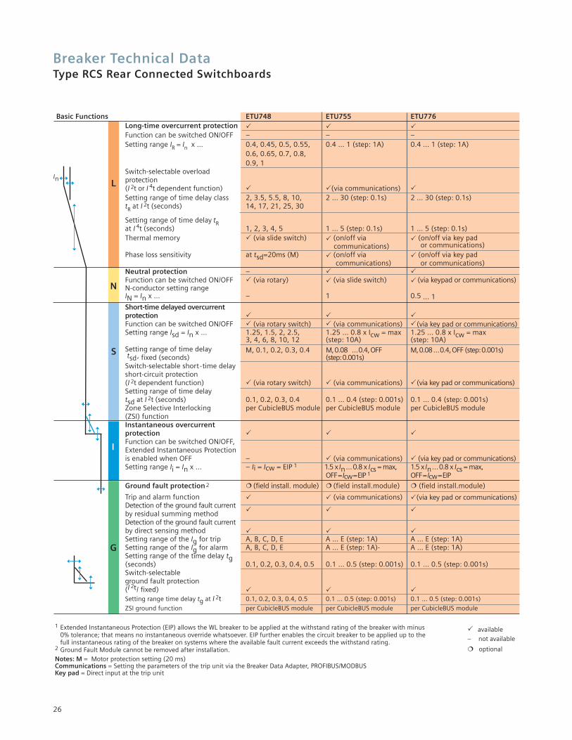
Basic Functions ETU748 ETU755 ETU776Long-time overcurrent protection � � �Function can be switched ON/OFF – – –Setting range IR = In x … 0.4, 0.45, 0.5, 0.55, 0.4 … 1 (step: 1A) 0.4 … 1 (step: 1A)
0.6, 0.65, 0.7, 0.8, 0.9, 1
Switch-selectable overload protection (I 2t or I 4t dependent function) � �(via communications) �Setting range of time delay class 2, 3.5, 5.5, 8, 10, 2 … 30 (step: 0.1s) 2 … 30 (step: 0.1s)tR at I 2t (seconds) 14, 17, 21, 25, 30
Setting range of time delay tRat I 4t (seconds) 1, 2, 3, 4, 5 1 … 5 (step: 0.1s) 1 … 5 (step: 0.1s)Thermal memory � (via slide switch) � (on/off via � (on/off via key pad
communications) or communications)Phase loss sensitivity at tsd=20ms (M) � (on/off via � (on/off via key pad
communications) or communications)Neutral protection – � �Function can be switched ON/OFF � (via rotary) � (via slide switch) � (via keypad or communications)N-conductor setting range IN = In x … – 1 0.5 … 1
Short-time delayed overcurrent protection � � �Function can be switched ON/OFF � (via rotary switch) � (via communications) �(via key pad or communications)Setting range Isd = In x … 1.25, 1.5, 2, 2.5, 1.25 … 0.8 x Icw = max 1.25 … 0.8 x Icw = max
3, 4, 6, 8, 10, 12 (step: 10A) (step: 10A)Setting range of time delay M, 0.1, 0.2, 0.3, 0.4 M,0.08 … 0.4,OFF M,0.08… 0.4,OFF (step:0.001s)tsd, fixed (seconds) (step:0.001s)
Switch-selectable short-time delayshort-circuit protection(I 2t dependent function) � (via rotary switch) � (via communications) �(via key pad or communications)Setting range of time delay tsd at I 2t (seconds) 0.1, 0.2, 0.3, 0.4 0.1 … 0.4 (step: 0.001s) 0.1 … 0.4 (step: 0.001s)Zone Selective Interlocking per CubicleBUS module per CubicleBUS module per CubicleBUS module(ZSI) functionInstantaneous overcurrent protection � � �Function can be switched ON/OFF, Extended Instantaneous Protectionis enabled when OFF – � (via communications) � (via key pad or communications)Setting range Ii = In x … – Ii = Icw = EIP 1 1.5 x In…0.8 x Ics = max, 1.5 x In…0.8 x Ics = max,
OFF=Icw=EIP 1 OFF=Icw=EIP
Ground fault protection 2 � (field install. module) � (field install.module) � (field install.module)
Trip and alarm function � � (via communications) �(via key pad or communications)Detection of the ground fault current
� � �by residual summing methodDetection of the ground fault currentby direct sensing method � � �Setting range of the Ig for trip A, B, C, D, E A … E (step: 1A) A … E (step: 1A)Setting range of the Ig for alarm A, B, C, D, E A … E (step: 1A)- A … E (step: 1A)Setting range of the time delay tg(seconds) 0.1, 0.2, 0.3, 0.4, 0.5 0.1 … 0.5 (step: 0.001s) 0.1 … 0.5 (step: 0.001s)Switch-selectable ground fault protection (I 2t/ fixed) � � �Setting range time delay tg at I 2t 0.1, 0.2, 0.3, 0.4, 0.5 0.1 … 0.5 (step: 0.001s) 0.1 … 0.5 (step: 0.001s)
ZSI ground function per CubicleBUS module per CubicleBUS module per CubicleBUS module
� available
– not available
� optional
L
N
S
I
G
1 Extended Instantaneous Protection (EIP) allows the WL breaker to be applied at the withstand rating of the breaker with minus 0% tolerance; that means no instantaneous override whatsoever. EIP further enables the circuit breaker to be applied up to the full instantaneous rating of the breaker on systems where the available fault current exceeds the withstand rating.
2 Ground Fault Module cannot be removed after installation.Notes: M = Motor protection setting (20 ms)Communications = Setting the parameters of the trip unit via the Breaker Data Adapter, PROFIBUS/MODBUSKey pad = Direct input at the trip unit
In
Breaker Technical DataType RCS Rear Connected Switchboards
27
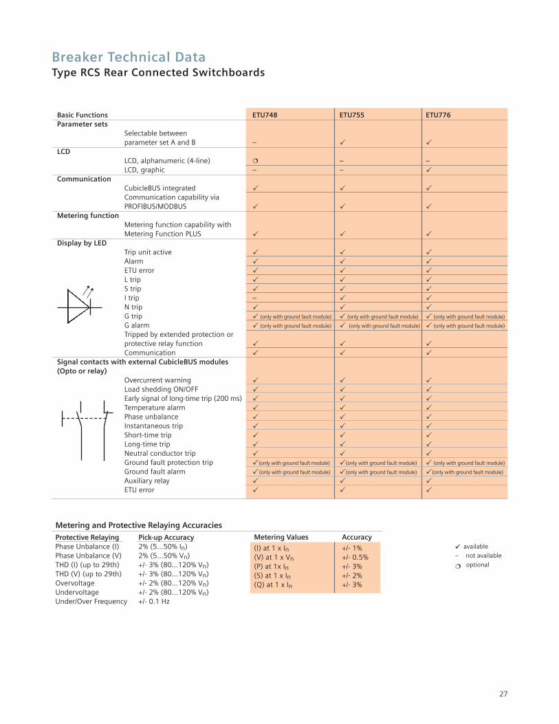
Basic Functions ETU748 ETU755 ETU776Parameter sets
Selectable between parameter set A and B – � �
LCDLCD, alphanumeric (4-line) � – –LCD, graphic – – �
CommunicationCubicleBUS integrated � � �Communication capability via PROFIBUS/MODBUS � � �
Metering functionMetering function capability with Metering Function PLUS � � �
Display by LEDTrip unit active � � �Alarm � � �ETU error � � �L trip � � �S trip � � �I trip – � �N trip � � �G trip � (only with ground fault module) � (only with ground fault module) � (only with ground fault module)
G alarm � (only with ground fault module) � (only with ground fault module) � (only with ground fault module)
Tripped by extended protection or protective relay function � � �Communication � � �
Signal contacts with external CubicleBUS modules (Opto or relay)
Overcurrent warning � � �Load shedding ON/OFF � � �Early signal of long-time trip (200 ms) � � �Temperature alarm � � �Phase unbalance � � �Instantaneous trip � � �Short-time trip � � �Long-time trip � � �Neutral conductor trip � � �Ground fault protection trip �(only with ground fault module) �(only with ground fault module) � (only with ground fault module)
Ground fault alarm �(only with ground fault module) �(only with ground fault module) �(only with ground fault module)
Auxiliary relay � � �ETU error � � �
�� available
– not available
� optional
Protective Relaying Pick-up AccuracyPhase Unbalance (I) 2% (5…50% In)Phase Unbalance (V) 2% (5…50% Vn)THD (I) (up to 29th) +/- 3% (80…120% Vn)THD (V) (up to 29th) +/- 3% (80…120% Vn)Overvoltage +/- 2% (80…120% Vn)Undervoltage +/- 2% (80…120% Vn)Under/Over Frequency +/- 0.1 Hz
Metering and Protective Relaying AccuraciesMetering Values Accuracy
(I) at 1 x In +/- 1%(V) at 1 x Vn +/- 0.5%(P) at 1x In +/- 3%(S) at 1 x In +/- 2%(Q) at 1 x In +/- 3%
Breaker Technical DataType RCS Rear Connected Switchboards
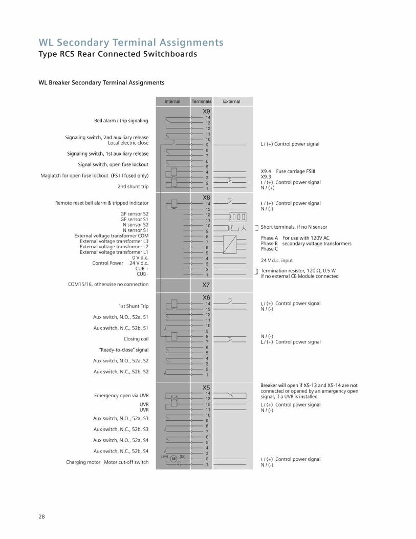
WL Secondary Terminal AssignmentsType RCS Rear Connected Switchboards
28
WL Breaker Secondary Terminal Assignments
WL Communications OverviewType RCS Rear Connected Switchboards
29
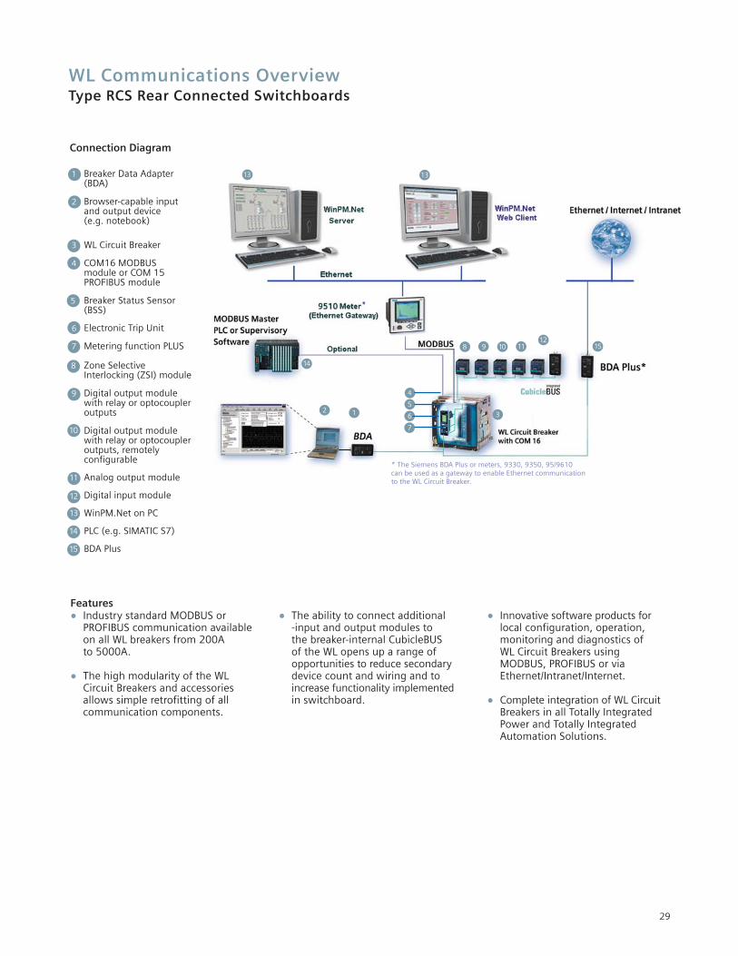
Connection Diagram
• Industry standard MODBUS orPROFIBUS communication available on all WL breakers from 200A to 5000A.
• The high modularity of the WL Circuit Breakers and accessories allows simple retrofitting of all communication components.
• The ability to connect additional -input and output modules to the breaker-internal CubicleBUS of the WL opens up a range of opportunities to reduce secondary device count and wiring and to increase functionality implemented in switchboard.
• Innovative software products for local configuration, operation, monitoring and diagnostics of WL Circuit Breakers using MODBUS, PROFIBUS or via Ethernet/Intranet/Internet.
• Complete integration of WL CircuitBreakers in all Totally Integrated Power and Totally Integrated Automation Solutions.
Features
1 Breaker Data Adapter(BDA)
2 Browser-capable inputand output device(e.g. notebook)
3 WL Circuit Breaker
4 COM16 MODBUSmodule or COM 15 PROFIBUS module
5 Breaker Status Sensor(BSS)
6 Electronic Trip Unit
7 Metering function PLUS
8 Zone Selective Interlocking (ZSI) module
9 Digital output modulewith relay or optocoupler outputs
10 Digital output modulewith relay or optocoupler outputs, remotely configurable
11 Analog output module
12 Digital input module
13 WinPM.Net on PC
14 PLC (e.g. SIMATIC S7)
15 BDA Plus
1 32
13 13
8 9 10 1112
4
5
6
7
14
15
* The Siemens BDA Plus or meters, 9330, 9350, 95/9610 can be used as a gateway to enable Ethernet communication to the WL Circuit Breaker.
Section ConfigurationsType RCS Rear Connected Switchboards
Blank orInstrument
Compartment
Feeder Breaker800, 1200(FS1 Only)
Feeder Breaker800, 1200(FS1 Only)
Feeder Breaker800, 1200(FS1 Only)
Main Breaker 4000, 5000,
(FS3 Only)
32 in.(813 mm)
Blank orInstrument
Compartment
Feeder Breaker800, 1200(FS1 Only)
Feeder Breaker800, 1200(FS1 Only)
Feeder Breaker800, 1200(FS1 Only)
Main Breaker 800, 1200,
1600, 2000, 2500, 3000, 3200
(FS2 Only)
22 in.(559 mm)
Blank orInstrument
Compartment
Feeder Breaker800, 1200(FS1 Only)
Feeder Breaker800, 1200(FS1 Only)
Feeder Breaker800, 1200(FS1 Only)
Main Breaker 800, 1200, 1600,
2000, 2500, 3000, 3200(FS2 Only)
22 in.(559 mm)
Blank orInstrument
Compartment
Feeder Breaker800, 1200(FS1 Only)
Feeder Breaker800, 1200(FS1 Only)
Feeder Breaker800, 1200(FS Only)
Main Breaker 4000, 5000(FS3 Only)
32 in.(813 mm)
ACompartment
BCompartment
CCompartment
DCompartment
FS2/FS3 Breakers(Compt Height = 22.5”)
ECompartment
FCompartment
GCompartment
HCompartment
ICompartment
JCompartment
FS1 Breakers(Compt Height = 15”)
Blank or Instrument
Compartment
Main Breaker800, 1200, 1600,
2000, 2500,3000, 3200(FS2 Only)
Feeder Breaker800, 1600,2000, 3200(FS2 Only)
22 in.(559 mm)
Feeder Breaker800, 1200, 1600,
2000, 2500,3000, 3200(FS2 Only)
Blank or Instrument
Compartment
Feeder Breaker800, 1200, 1600,
2000, 2,500,3000, 3200(FS2 Only)
Feeder Breaker800, 1200, 1600,
2000, 2,500,3000, 3200(FS2 Only)
22 in.(559 mm)
Main Breaker800, 1200, 1600,
2000, 2,500,3000, 3200(FS2 Only)
Blank or Instrument
Compartment
Blank or Instrument
Compartment
22 in.(559 mm)
Feeder Breaker800, 1200, 1600,
2000, 2,500,3000, 3200(FS2 Only)
Main Breaker800, 1200, 1600,
2000, 2,500,3000, 3200(FS2 Only)
Blank or Instrument
Compartment
Main Breaker4000, 5000(FS3 Only)
Feeder Breaker800, 1200, 1600, 2000, 2500, 3000,
3200, 4000 (FS2 or FS3)
Refer to Note 1
Feeder Breaker800, 1200, 1600, 2000 (FS2 Only)
Refer to Note 1
22 in.(559 mm)
32 in.(813 mm)
Blank or Instrument
Compartment
Blank or Instrument
Compartment
Main Breaker4000, 5000(FS3 Only)
Refer to Note 6
Feeder Breaker800, 1200,1600, 2000(FS2 Only)
32 in.(813 mm)
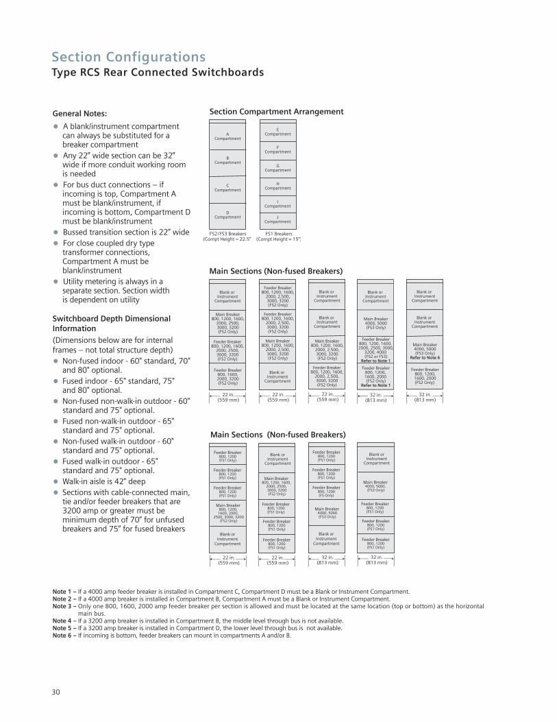
Section Compartment ArrangementGeneral Notes:
• A blank/instrument compartment can always be substituted for a breaker compartment
• Any 22” wide section can be 32” wide if more conduit working room is needed
• For bus duct connections – if incoming is top, Compartment A must be blank/instrument, if incoming is bottom, Compartment Dmust be blank/instrument
• Bussed transition section is 22” wide
• For close coupled dry type transformer connections,Compartment A must be blank/instrument
• Utility metering is always in a separate section. Section width is dependent on utility
Switchboard Depth DimensionalInformation
(Dimensions below are for internalframes – not total structure depth)
• Non-fused indoor - 60" standard, 70"and 80" optional.
• Fused indoor - 65" standard, 75" and 80" optional.
• Non-fused non-walk-in outdoor - 60"standard and 75" optional.
• Fused non-walk-in outdoor - 65" standard and 75" optional.
• Non-fused walk-in outdoor - 60" standard and 75" optional.
• Fused walk-in outdoor - 65" standard and 75" optional.
• Walk-in aisle is 42" deep
• Sections with cable-connected main,tie and/or feeder breakers that are 3200 amp or greater must be minimum depth of 70” for unfused breakers and 75” for fused breakers
Main Sections (Non-fused Breakers)
Note 1 – If a 4000 amp feeder breaker is installed in Compartment C, Compartment D must be a Blank or Instrument Compartment.Note 2 – If a 4000 amp breaker is installed in Compartment B, Compartment A must be a Blank or Instrument Compartment.Note 3 – Only one 800, 1600, 2000 amp feeder breaker per section is allowed and must be located at the same location (top or bottom) as the horizontal
main bus.Note 4 – If a 3200 amp breaker is installed in Compartment B, the middle level through bus is not available.Note 5 – If a 3200 amp breaker is installed in Compartment D, the lower level through bus is not available.Note 6 – If incoming is bottom, feeder breakers can mount in compartments A and/or B.
30
Main Sections (Non-fused Breakers)
Section ConfigurationsType RCS Rear Connected Switchboards
Tie Breaker800,1200,1600,
2000, 2500, 3000, 3200(FS2 Only)
Feeder Breaker800,1200,1600,
2000, 2500, 3000, 3200(FS2 Only)
Feeder Breaker800, 1200,1600, 2000(FS2 Only)
Feeder Breaker800, 1200,1600, 2000(FS2 Only)
22 in.(559 mm)
Tie Breaker800, 1200,1600,
2000, 2500, 3000, 3200(FS2 Only)
Feeder Breaker800, 1200,1600, 2000(FS2 Only)
Feeder Breaker800, 1200,1600, 2000(FS2 Only)
Feeder Breaker800, 1200, 1600, 2000(FS2 Only)
22 in.(559 mm)
Tie Breaker4000
(FS3 Only)
Feeder Breaker800, 1200, 1600,
2000, 2500, 3000, 3200, 4000(FS2 or FS3)
Refer to Note 1
Feeder Breaker800, 1200,
1600, 2000 (FS2 Only)
Refer to Note 1
32 in.(813 mm)
Feeder Breaker800, 1200,1600, 2000(FS2 Only)
Tie Breaker4000, 5000(FS3 Only)
Feeder Breaker800, 1200,1600, 2000(FS2 Only)
32 in.(813 mm)
Feeder Breaker800, 1200,1600, 2000(FS2 Only)
Refer to Note 2
Feeder Breaker800, 1200, 1600,
2000, 2500, 3000, 3200, 4000(FS2 or FS3)
Refer to Note 1
Tie Sections (Non-fused Breakers)
Blank orInstrument
Compartment
Feeder Breaker800, 1200(FS1 Only)
Feeder Breaker800, 1200(FS1 Only)
Feeder Breaker800, 1200(FS1 Only)
Tie Breaker 800, 1200,
1600, 2000, 2500, 3000, 3200
(FS2 Only)
22 in.(559 mm)
Blank orInstrument
Compartment
Feeder Breaker800, 1200(FS1 Only)
Feeder Breaker800, 1200(FS1 Only)
Feeder Breaker800, 1200(FS1 Only)
Tie Breaker 800, 1200, 1600,
2000, 2500, 3000, 3200(FS2 Only)
22 in.(559 mm)
Blank orInstrument
Compartment
32 in.(813 mm)
Tie Breaker 4000, 5000(FS3 Only)
Feeder Breaker800, 1200(FS1 Only)
Feeder Breaker800, 1200(FS1 Only)
Feeder Breaker800, 1200(FS1 Only)
Blank orInstrument
Compartment
Main Breaker800, 1600,
2000
Feeder Breaker800, 1600,
2000
Feeder Breaker800, 1600,
2000
22 in.(559 mm)
Blank orInstrument
Compartment
Main Breaker800, 1600,
2000
Feeder Breaker800, 1600,
2000
Blank orInstrument
Compartment
22 in.(559 mm)
Blank orInstrument
Compartment
Main Breaker3200, 4000
Feeder Breaker800, 1600, 2000
32 in.(813 mm)
Blank orInstrument
Compartment
Main Breaker5000
32 in.(813 mm)
Blank orInstrument
Compartment
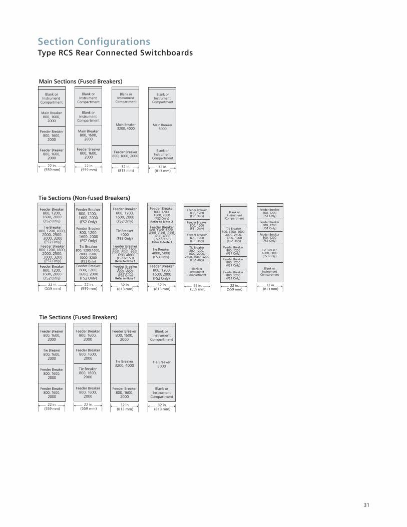
Main Sections (Fused Breakers)
Tie Breaker800, 1600,
2000
Feeder Breaker800, 1600,
2000
Feeder Breaker800, 1600,
2000
Feeder Breaker800, 1600,
2000
22 in.(559 mm)
Tie Breaker800, 1600,
2000
Feeder Breaker800, 1600,
2000
Feeder Breaker800, 1600,
2000
Feeder Breaker800, 1600,
2000
22 in.(559 mm)
Tie Breaker3200, 4000
Feeder Breaker800, 1600,
2000
32 in.(813 mm)
Feeder Breaker800, 1600,
2000
Tie Breaker5000
Blank orInstrument
Compartment
32 in.(813 mm)
Blank orInstrument
Compartment
Tie Sections (Fused Breakers)
31
Section ConfigurationsType RCS Rear Connected Switchboards
32
Blank orInstrument
Compartment
Feeder Breaker800, 1200,1600, 2000(FS2 Only)
22 in.(559 mm)
Main Breaker 800, 1200,
1600, 2000, 2500, 3000, 3200
(FS2 Only)
Tie Breaker 800, 1200,
1600, 2000, 2500, 3000, 3200
(FS2 Only)
22 in.(559 mm)
Feeder Breaker800, 1200,1600, 2000(FS2 Only)
Feeder Breaker800, 1200,1600, 2000(FS2 Only)
Tie Breaker 800, 1200,
1600, 2000, 2500, 3000, 3200
(FS2 Only)
Main Breaker 800, 1200,
1600, 2000, 2500, 3000, 3200
(FS2 Only)
Blank orInstrument
Compartment
Main Breaker800, 1200,1600, 2000(FS2 Only)
Tie Breaker800, 1200,1600, 2000(FS2 Only)
Main Breaker800, 1600,
2000(FS2 Only)
22 in.(559 mm)
Blank orInstrument
Compartment
Main Breaker4000
(FS3 Only)
Tie Breaker 4000
(FS3 Only)
Feeder Breaker800, 1200,
1600, 2000 (FS2 Only)
32 in.(813 mm)
Main Breaker4000
(FS3 Only)
Tie Breaker 4000
(FS3 Only)
32 in.(813 mm)
Feeder Breaker800, 1200,1600, 2000(FS2 Only)
Feeder Breaker800, 1200,1600, 2000(FS2 Only)
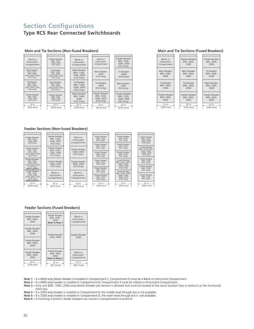
Main and Tie Sections (Non-fused Breakers)
Blank orInstrument
Compartment
Main Breaker800, 1600,
2000
Tie Breaker800, 1600,
2000
Feeder Breaker800, 1600,
2000
22 in.(559 mm)
Main Breaker800, 1600,
2000
Tie Breaker800, 1600,
2000
Feeder Breaker800, 1600,
2000
22 in.(559 mm)
Feeder Breaker800, 1600,
2000
Tie Breaker800, 1600,
2000
Main Breaker800, 1600,
2000
Feeder Breaker800, 1600,
2000
22 in.(559 mm)
Feeder Breaker800, 1600,
2000
Main and Tie Sections (Fused Breakers)
22 in.(559 mm)
Feeder Breaker800, 1200,1600, 2000(FS2 Only)
Feeder Breaker 800, 1200,
1600, 2000, 2500, 3000, 3200
(FS2 Only)
Feeder Breaker 800, 1200,
1600, 2000, 2500, 3000, 3200
(FS2 Only)Refer to Note 4
Feeder Breaker 800, 1200,
1600, 2000, 2500, 3000, 3200
(FS2 Only)Refer to Note 5
Feeder Breaker800, 1200,1600, 2000(FS2 Only)
Feeder Breaker800, 1200,1600, 2000(FS2 Only)
Feeder Breaker4000, 5000(FS3 Only)
32 in.(813 mm)
Blank orInstrument
Compartment
Feeder Breaker4000, 5000(FS3 Only)
32 in.(813 mm)
Blank orInstrument
Compartment
Feeder Breaker4000, 5000(FS3 Only)
Blank orInstrument
Compartment
Feeder Breaker800, 1200(FS1 Only)
Feeder Breaker800, 1200(FS1 Only)
Feeder Breaker800, 1200(FS1 Only)
Feeder Breaker800, 1200(FS1 Only)
Feeder Breaker800, 1200(FS1 Only)
Feeder Breaker800, 1200(FS1 Only)
22 in.(559 mm)
Feeder Breaker800, 1200(FS1 Only)
Feeder Breaker800, 1200(FS1 Only)
Feeder Breaker800, 1200(FS1 Only)
Feeder Breaker800, 1200, 1600,
2000, 2500, 3000, 3200(FS2 Only)
Feeder Breaker800, 1200, 1600,
2000, 2500, 3000, 3200(FS2 Only)
22 in.(559 mm)
Feeder Breaker800, 1200(FS1 Only)
Feeder Breaker800, 1200(FS1 Only)
Feeder Breaker800, 1200(FS1 Only)
Feeder Breaker800, 1200,1600, 2000(FS2 Only)
Feeder Breaker800, 1200,1600,
2000, 2500, 3000, 3200(FS2 Only)
22 in.(559 mm)
Feeder Sections (Non-fused Breakers)
Feeder Breaker800, 1600,
2000
Feeder Breaker800, 1600,
2000
Feeder Breaker800, 1600,
2000
22 in.(559 mm)
Feeder Breaker800, 1600,
2000
Feeder Breaker800, 1600,
2000Refer to Note 3
Feeder Breaker3200, 4000
32 in.(813 mm)
Feeder Breaker800, 1600
2000Refer to Note 3
Blank orInstrument
Compartment
Feeder Breaker5000
32 in.(813 mm)
Blank orInstrument
Compartment
Feeder Sections (Fused Breakers)
Note 1 – If a 4000 amp feeder breaker is installed in Compartment C, Compartment D must be a Blank or Instrument Compartment.Note 2 – If a 4000 amp breaker is installed in Compartment B, Compartment A must be a Blank or Instrument Compartment.Note 3 – Only one 800, 1600, 2000 amp feeder breaker per section is allowed and must be located at the same location (top or bottom) as the horizontal
main bus.Note 4 – If a 3200 amp breaker is installed in Compartment B, the middle level through bus is not available.Note 5 – If a 3200 amp breaker is installed in Compartment D, the lower level through bus is not available.Note 6 – If incoming is bottom, feeder breakers can mount in compartments A and/or B.

Shipping Weight / Dimensional InformationType RCS Rear Connected Switchboards
33
Approximate Weight – Lbs.
Section Type 22" 22" 32" 32" 38" 38" 48" 48"Indoor Outdoor Indoor Outdoor Indoor Outdoor Indoor Outdoor
Auxiliary 1000 2000 1300 2500 1800 3200 N/A N/A(450) (900) (585) (1125) (810) (1440)
Utility N/A N/A N/A N/A 2100 3500 2600 4500Metering (945) (1575) (1170) (2025)
Breaker 1400 2400 2000 3300 N/A N/A N/A N/A(630) (1080) (900) (1485)
Weights shown in pounds and ( ) kilograms.Weights shown do not include weight of circuit breaker removable element (but does include cradle). Add 400 lbs for hoist and track.On outdoor switchboard, add 500 lbs for end walls (weight is for both ends). Refer to shipping documents for actual weights.
Siemens Type RCS Switchboard can beconfigured in many ways by combiningdifferent section types. Up to five vertical sections plus a transition section can be shipped together as a unit.
Maximum shipping split length is110in. (2794 mm). If all vertical sections are not to be shipped as a unit, specifications need to be providedthat describe the limiting factors (e.g.,low door or narrow hallway).
Normal indoor vertical sections are 96 in. (2438 mm) high and a minimum 60 in. (1524 mm) deep. A top-mounted hoist, which is shipped as an accessory in a separate container, adds 6.2 in. (157 mm) for a total installed height of 102.2 in. (2596 mm).
The outdoor switchboard assembly contains the indoor assembly in an outdoor housing. The overall height is112.8 in. (2865 mm) for non walk-indesigns and 114 in. (2896 mm) forwalk-in designs. The depth of a
non walk-in outdoor assembly with a 60 in. (1524 mm) internal structure is82.3 in. (2090 mm) and the depth of awalk-in outdoor assembly with a 60 in.(1524 mm) internal structure is 110.7in. (2812 mm). Maximum shippingsplit length for outdoor structures is 66 in. (1676 mm).
The major assembly sections include:• Transition Sections — used as
transition to liquid filled transformer or to outdoor dry type transformers.
• Auxiliary Sections — used as incoming bus duct or cable entrance when a main breaker is not used.
• Main Sections — used to contain main breaker and may house metering and feeder breakers.
• Feeder Sections — used to feeder contain breakers and other equipment such as instrumentation.
• Tie Sections — used to contain tie breaker and other equipment such as feeder breakers.
Transition Section For Liquid Filled andOutdoor Dry Type Transformers
Dimension A Weightin inches (mm) in lbs. (kg)
Indoor 55 (1397) 500 (227)Outdoor 61 (1549) 550 (250)
Shipping Weight / Dimensional InformationType RCS Rear Connected Switchboards
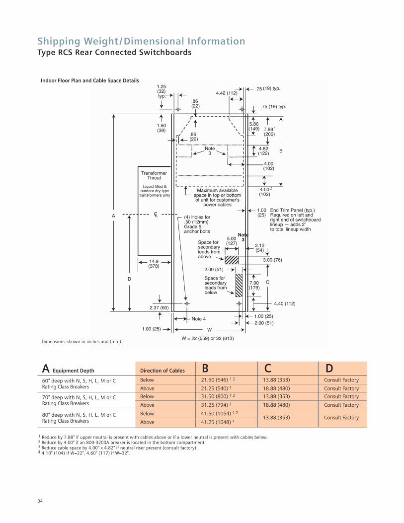
Equipment Depth Direction of Cables
Below 21.50 (546) 1 2 13.88 (353) Consult Factory
Above 21.25 (540) 1 18.88 (480) Consult Factory
Below 31.50 (800) 1 2 13.88 (353) Consult Factory
Above 31.25 (794) 1 18.88 (480) Consult Factory
Below 41.50 (1054) 1 213.88 (353) Consult Factory
Above 41.25 (1048) 1
A B C D
1 Reduce by 7.88” if upper neutral is present with cables above or if a lower neutral is present with cables below.2 Reduce by 4.00” if an 800-3200A breaker is located in the bottom compartment.3 Reduce cable space by 4.00” x 4.82” if neutral riser present (consult factory).4 4.10” (104) if W=22”, 4.60” (117) if W=32”.
1.25(32) typ.
1.50(38)
.86(22)
.86(22)
4.42 (112).75 (19) typ.
.75 (19) typ.
5.86(149) 7.88
(200)
Maximum availablespace in top or bottomof unit for customer's
power cables
TransformerThroat
Liquid filled &outdoor dry typetransformers only
(4) Holes for .50 (12mm)Grade 5anchor bolts
CL
B
End Trim Panel (typ.)Required on left andright end of switchboardlineup — adds 2”to total lineup width
A
14.9(378)
D
Space forsecondaryleads fromabove
Space forsecondaryleads frombelow
5.00(127) 2.12
(54)
3.00 (76)
2.00 (51)
7.00(179)
2.37 (60)
1.00 (25) W
W = 22 (559) or 32 (813)
2.00 (51)1.00 (25)
4.40 (112)
C
4.00(102)
4.00(102)
4.82(122)
1.00(25)
2
1
Note3
Note3
Note 4
Indoor Floor Plan and Cable Space Details
34
Dimensions shown in inches and (mm).
60" deep with N, S, H, L, M or C Rating Class Breakers
70" deep with N, S, H, L, M or C Rating Class Breakers
80" deep with N, S, H, L, M or C Rating Class Breakers
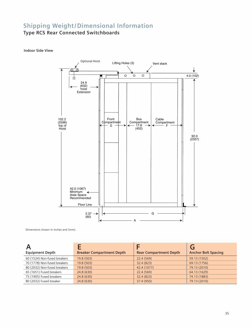
Shipping Weight / Dimensional InformationType RCS Rear Connected Switchboards
35
Optional Hoist
24.9(632)hoist
Extension
102.2 (2596)top ofHoist
Lifting Holes (3) Vent stack
Front Compartment
E
BusCompartment
17.8(452)
CableCompartment
F
42.0 (1067) MinimumAisle SpaceRecommended
Floor Line
2.37(60)
92.0(2337)
4.0 (102)
A
G
Equipment Depth Breaker Compartment Depth Rear Compartment Depth Anchor Bolt Spacing
60 (1524) Non-fused breakers 19.8 (503) 22.4 (569) 59.13 (1502)70 (1778) Non-fused breakers 19.8 (503) 32.4 (823) 69.13 (1756)80 (2032) Non-fused breakers 19.8 (503) 42.4 (1077) 79.13 (2010)65 (1651) Fused breakers 24.8 (630) 22.4 (569) 64.13 (1629)75 (1905) Fused breakers 24.8 (630) 32.4 (823) 74.13 (1883)80 (2032) Fused breaker 24.8 (630) 37.4 (950) 79.13 (2010)
A E F G
Dimensions shown in inches and (mm).
Indoor Side View
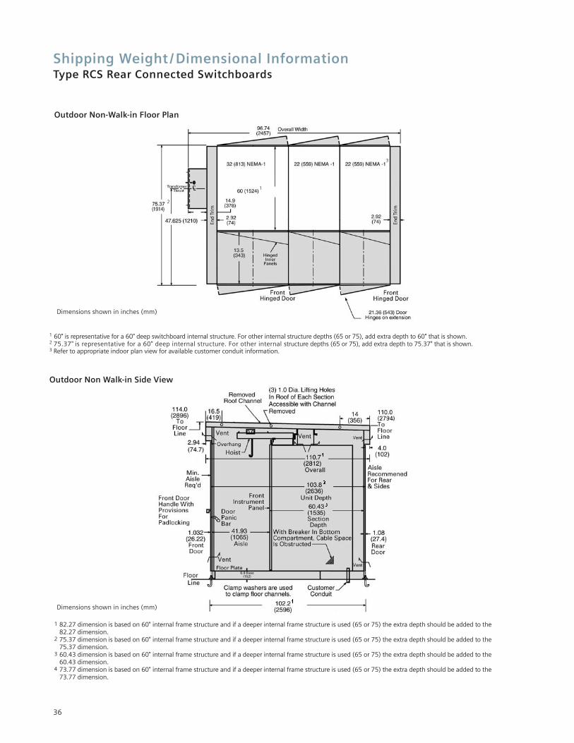
Shipping Weight / Dimensional InformationType RCS Rear Connected Switchboards
36
1 82.27 dimension is based on 60" internal frame structure and if a deeper internal frame structure is used (65 or 75) the extra depth should be added to the 82.27 dimension.
2 75.37 dimension is based on 60" internal frame structure and if a deeper internal frame structure is used (65 or 75) the extra depth should be added to the 75.37 dimension.
3 60.43 dimension is based on 60" internal frame structure and if a deeper internal frame structure is used (65 or 75) the extra depth should be added to the60.43 dimension.
4 73.77 dimension is based on 60" internal frame structure and if a deeper internal frame structure is used (65 or 75) the extra depth should be added to the 73.77 dimension.
Dimensions shown in inches (mm)
Outdoor Non-Walk-in Floor Plan
Outdoor Non Walk-in Side View
1 60" is representative for a 60" deep switchboard internal structure. For other internal structure depths (65 or 75), add extra depth to 60" that is shown.2 75.37" is representative for a 60" deep internal structure. For other internal structure depths (65 or 75), add extra depth to 75.37" that is shown.3 Refer to appropriate indoor plan view for available customer conduit information.
1
3
2
Dimensions shown in inches (mm)
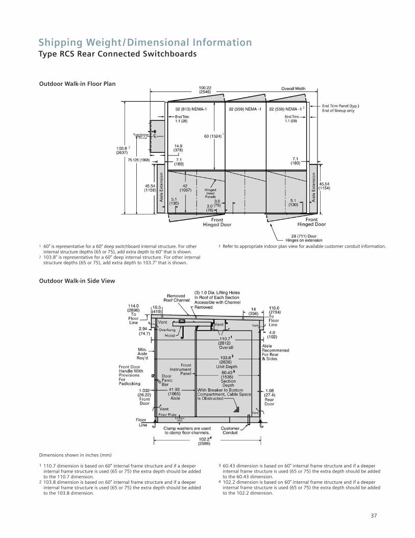
37
Shipping Weight / Dimensional InformationType RCS Rear Connected Switchboards
Dimensions shown in inches (mm)
1 110.7 dimension is based on 60" internal frame structure and if a deeper internal frame structure is used (65 or 75) the extra depth should be added to the 110.7 dimension.
2 103.8 dimension is based on 60" internal frame structure and if a deeper internal frame structure is used (65 or 75) the extra depth should be added to the 103.8 dimension.
3 60.43 dimension is based on 60" internal frame structure and if a deeperinternal frame structure is used (65 or 75) the extra depth should be added to the 60.43 dimension.
4 102.2 dimension is based on 60" internal frame structure and if a deeper internal frame structure is used (65 or 75) the extra depth should be added to the 102.2 dimension.
Outdoor Walk-in Side View
Outdoor Walk-in Floor Plan
2
1 60" is representative for a 60" deep switchboard internal structure. For other internal structure depths (65 or 75), add extra depth to 60" that is shown.
2 103.8" is representative for a 60" deep internal structure. For other internal structure depths (65 or 75), add extra depth to 103.7" that is shown.
3 Refer to appropriate indoor plan view for available customer conduit information.
1
3
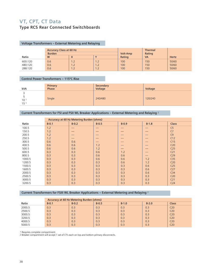
VT, CPT, CT DataType RCS Rear Connected Switchboards
38
Accuracy Class at 60 Hz ThermalBurden Volt-Amp Rating
Ratio W X Y Rating VA Hertz
600:120 0.6 1.2 1.2 100 150 50/60480:120 0.6 1.2 1.2 100 150 50/60288:120 0.6 1.2 1.2 100 150 50/60
Voltage Transformers – External Metering and Relaying
Primary Secondary kVA Phase Voltage Voltage
35
Single 240/480 120/24010 1
15 1
Control Power Transformers – 115ºC Rise
Accuracy at 60 Hz Metering Burden (ohms)
Ratio B-0.1 B-0.2 B-0.5 B-0.9 B-1.8 Class
100.5 1.2 — — — — C5150.5 1.2 — — — — C7200.5 1.2 — — — — C9250.5 1.2 — — — — C12300.5 0.6 0.6 — — — C15400.5 0.6 0.6 1.2 — — C20500.5 0.6 0.6 1.2 — — C25600.5 0.3 0.3 0.6 1.2 — C21800.5 0.3 0.3 0.6 0.6 — C291000.5 0.3 0.3 0.6 0.6 1.2 C351200.5 0.3 0.3 0.3 0.6 1.2 C201500.5 0.3 0.3 0.3 0.3 0.6 C251600.5 0.3 0.3 0.3 0.3 0.6 C272000.5 0.3 0.3 0.3 0.3 0.6 C342500.5 0.3 0.3 0.3 0.3 0.3 C203000.5 0.3 0.3 0.3 0.3 0.3 C213200.5 0.3 0.3 0.3 0.3 0.3 C24
Current Transformers for FSI and FSII WL Breaker Applications – External Metering and Relaying 2
1 Requires complete compartment. 2 Breaker compartment will accept 1 set of CT's each on top and bottom primary disconnects.
Accuracy at 60 Hz Metering Burden (ohms)Ratio B-0.1 B-0.2 B-0.5 B-1.0 B-2.0 Class
2000.5 0.3 0.3 0.3 0.3 0.3 C202500.5 0.3 0.3 0.3 0.3 0.3 C203000.5 0.3 0.3 0.3 0.3 0.3 C203200.5 0.3 0.3 0.3 0.3 0.3 C204000.5 0.3 0.3 0.3 0.3 0.3 C205000.5 0.3 0.3 0.3 0.3 0.3 C20
Current Transformers for FSIII WL Breaker Applications – External Metering and Relaying 2
Guide Form SpecificationsType RCS Rear Connected Switchboards
SECTION SWITCHBOARDSPART 1 – GENERAL1.1 SCOPEA. This section defines switchboard
assemblies with drawout circuit breaker elements for use in ac systems, rated 600 V or less.
1.2 RELATED DOCUMENTSA. Drawings and general provisions of
the Contract, including General and Supplementary Conditions and Division 1 Specification Sections, apply to this Section.
B. Related Sections (where applicable) include the following:1. Section 16345 - Medium Voltage
Load Break Switches2. Section 16470 - Dry Type
Substation Transformers3. Section 16490 - Liquid Type
Substation Transformers
1.3 SUBMITTALSA. Submit shop drawings and product
data for approval and final documentation in the quantities listed according to the Conditions of the Contract. Customer name, customer location, and customer order number shall identify all transmittals.
B. Documents for Approval: General arrangement drawing showing dimensioned elevation, floor plan, side view and foundation details, one-line diagram showing major features, nameplate legends, schematic diagrams and bill of material.
C. Final Documents: Record documentation to include those in 1.3.B and wiring diagrams, list of recommended spare parts, instruction and installation manuals [and certified test reports]
D. Product Data: Include features, characteristics, and ratings of individual circuit breakers and other components. Also, time-current characteristic curves for over current protective devices, including circuit-breaker trip devices and fusible devices.
E. [Manufacturer Seismic Qualification]:Switchboard, and associated breakers, shall meet and be certified to seismic requirements specified in the [IBC International Building Code] [UBC Uniform Building Code Zone 2] [UBC Uniform Building Code Zone 4] [CBC California Building Code Zone 4][SBC Standard Building Code] [BOCA Building Code] [IEEE 693]. Mounting and anchorage requirements shall be supplied by the switchboard manufacturer.
1.4 QUALITY ASSURANCEA. Manufacturer Qualifications:
Manufacturer of this equipment shall have a minimum of 5 years experience producing similar electrical equipment. The manufacturer of the switchboardassembly shall be the same manufacturer as the breakers. The manufacturer shall be ISO 9001 or 9002 certified.
B. Comply with requirements of latest revisions of applicable industrystandards, specifically including the following:1. UL 891 Switchboards 2. NEMA PB2 – Deadfront
distribution switchboards.3. UL 489 – Molded-case circuit
breakers, molded-case switches and circuit breaker enclosures.
4. UL 1066 – Low Voltage AC and DC power circuit breakers used in enclosures.
5. ANSI C37.13 – Low Voltage AC power circuit breakers used in enclosures.
6. ANSI C37.16 – Preferred ratings, related requirements and application for low voltage power circuit breakers and AC power circuit protectors.
7. ANSI C37.17 – Trip devices for AC and general purpose DC low voltage power circuit breakers.
8. NEMA SG3 – Low voltage power circuit breakers
1.5 DELIVERY, STORAGE, AND HANDLING
A. Deliver products in factory labeled packages. Shipping groups shall not exceed 15 ft. in length.
B. Circuit breakers shall be shipped inside their respective cells in which they were factory acceptance tested.
C. Store and handle in strict compliance with manufacturer’s instructions and recommendations. Protect from potential damage from weather and construction operations. Store so condensation will not form on or in switchboard and if necessary, apply temporary heat where required to obtain suitable service conditions.
PART 2 - PRODUCTS2.1 MANUFACTURERSA. The switchboard assembly shall be
manufactured by Siemens Energy & Automation, or approved equal.
2.2 RATINGSA. System Configuration: switchboard
suitable for application in [three-phase] [60 Hz] [50 Hz], [3 wire] [4 wire] [grounded-neutral] [3 wire ungrounded] [3 wire high-impedance grounded] system.
B. Electrical Ratings:1. Nominal System Voltage: [600 V]
[480 V] [240 V] [208 V] [OTHER].2. Maximum Design Voltage:
[600 volts]3. Short-Circuit Current:
[100kA] [150kA] [200kA] 4. Main-Bus Continuous Current:
[1600] [2000] [2500] [3000] [4000] [5000] [6000] A.
5. [Neutral Bus Continuous Current:][50] [100] [200] percent of main phase bus, up to 8000A maximum.
2.3 SWITCHBOARD GENERAL CONSTRUCTION
A. The switchboard shall be factory assembled and tested, and comply with applicable industry standards. It shall be a coordinated design so that shipping groups are easily connected together at the site into a continuous line-up. Necessary connecting materials shall be furnished. All low voltage circuit breakers and assemblies shall be produced by a single manufacturer.
39
Guide Form SpecificationsType RCS Rear Connected Switchboards
B. The switchboard assembly shall consist of one or more metal-enclosed sections in an [indoor NEMA 1 enclosure] [out-door NEMA 3R non walk-in enclosure] [outdoor NEMA 3R walk-in enclosure]. 1. End sections shall include
provisions for main bus extensionand installation of future. vertical sections.
2. The design shall incorporate preformed steel channels, angles,and structural components boltedtogether and reinforced to form a rigid, self-supporting assembly.
3. Fabricate enclosure with removable, [rear cover panels, secured by captive screws], [hinged rear doors with captive screws] [hinged rear doors with three-point latch and padlockable handle] to allow access to rear interior of switchboard.
C. Front breaker doors must be free of any ventilation openings.
D. Horizontal barriers are to be provided to form individual circuit breaker or metering compartments. Circuit breaker compartments are to be barriered from the bus compartment through a primarydisconnect assembly. Each circuit breaker or metering compartment shall be provided with a hinged frontdoor secured with hand-operated [pad-lockable] [key-lockable]rotary latches.
E. Circuit breaker compartments shall include stationary primary contact disconnects that shall be silver-plated copper at the connection points and of one-piece construction.1. The upper set of disconnects shall
bolt directly to the main bus and, for feeder circuit breakers, the lower set shall extend to the rear cable area and shall be insulated where they pass through the main bus compartment.
2. Primary disconnects shall be sizedfor the maximum continuous current for the frame size of the circuit breaker which is located in the compartment.
3. Interlocks shall be provided to prevent a circuit breaker element of the incorrect frame size or interrupting rating from being
inserted into the compartment.4. Secondary control and
communication connections, when required, shall be accessible from the front of the switchboard without exposing any power cables or bussing. The secondary control contacts shall be of the sliding contact design, silver-plated and engage the drawout circuit breaker element in the “connected” and “test” positions.
F. All control wiring within the assembly shall be continuous and shall terminate on each end at a suitable terminal block. Control wiring shall be 18-gauge minimum, stranded type [MTW] [SIS] and shall be labeled at each end with sleeve-type wire markers.1. Wire markers shall be machine
imprinted with the wire name as indicated on the wiring diagrams.
2. Terminals shall be pressure wire connectors except where connecting to components that do not accept these terminations. Control wiring for external connections shall beterminated in a separate front accessible compartment for ease of access.
G. Finish: Painted steel parts shall be prepared for painting by a five-stage wash system consisting of an alkaline cleaner, fresh water rise, iron phosphate treatment, fresh water rise and non-chromate sealer. After cleaning and stabilization, the steel parts shall be coated with a thermosetting polyester powder applied with electrostatic equipment at a nominal 2 mils dry film thickness and then cured properly. The paint finish shall have a salt spray rating as defined in ASTM B-117. Paint color shall be ANSI 61 light gray.
H. Bus isolation barriers shall be arranged to isolate the buses on either side of each main and tie circuit breaker from each other.
I. [Incoming line isolation barriers shallbe arranged to isolate the incoming line connections from the main horizontal and vertical bus].
J. Main bus shall connect vertical sections and shall be uniform capacity the entire length of assembly. Vertical and horizontal
bus bar shall utilize a channel shape design to maximize short circuit withstand capability and minimize heat rise. The main horizontal bus shall be run in a vertical, edge-to-edge arrangement for high short circuit strength. Access to the rear cable termination area shall be possible without reaching over the main and vertical bus. 1. Bus shall be [98 % minimum
conductivity copper silver-plated over entire length of the bus bar] [98% conductivity copper tin-plated over entire length of the bus bar].
2. Feeder Circuit-Breaker Load Terminals: Plated copper bus extensions equipped with pressure connectors for outgoing circuit conductors.
3. Ground Bus shall be copper of 98% minimum conductivity, minimum size 1/4 by 3 inches.
4. Bus bracing shall be equal to the short circuit interrupting rating of the lowest rated circuit breakerapplied in the assembly or 100kA minimum.
5. Provide for future extensions from either end of main phase, neutral, and ground bus by means of pre-drilled bolt holes and connecting links.
K. [Bus/Cable compartment barriers: Barriers shall be supplied to isolate the rear cable area from the main bus area.]
L. [Insulated bus bar shall consist of bus bars enclosed in factory-applied, flame-retardant UL recognized insulation system. Bolted bus joints shall be insulated with secure joint covers that can easily be removed and reinstalled.]
M.[Low Voltage High-Resistance Grounding System] [Installed in the switchboard assembly] [Contained inseparate NEMA 1 enclosure] for use on [480 V] [600 V] [wye] [delta] source, including the following components:1. Meter relay (MR)2. 3 Indicating lights: white for
“Normal,” red for “Ground Fault” green for “Pulsing”
3. “Reset” push button 4. “Test” push button 5. On – Off switches for system
and pulse
40
Guide Form SpecificationsType RCS Rear Connected Switchboards
6. Repeat cycle timer, set to produce approx. 30 current pulses per minute
7. Neutral grounding resistor assembly8. Pulse resistor assembly9. Test resistor assembly
10. Relay for repeat cycle timer11. Alarm relay, with extra interlocks
for remote alarm (59X)12. Control power transformer 13. Neutral ammeter and current
transformer14. Optional Portable clamp on
ammeter15. [3 Grounding transformers for
generating a neutral CPT] (For Delta System without a system neutral)
N. [Outdoor NEMA 3R Non Walk-In enclosure shall consist of indoor switchboard assemblies in weather-resistant steel housing. Enclosure shall be painted steel, integral structural-steel base frame with factory-applied asphalt undercoating. Each section shall be equipped with the following features:]1. Structural design and anchorage
adequate to resist loads imposed by 125-mph wind.
2. Space heater operating at [full] [one-half of] rated voltage, sized to prevent condensation.
3. Louvers equipped with insect/rodent screen and filter andarranged to permit air circulation while excluding exterior dust and rodents.
4. Internal aisle of sufficient width to permit protective-device withdrawal.
5. [Load center for distribution of power to lights, receptacles and heaters.]
6. [Incandescent lighting receptacles with three-way switch.]
7. [Duplex receptacle with ground fault protection.]
O. [Outdoor NEMA 3R Walk-In enclosure shall consist of indoor switchboard assemblies in weather-resistant steel housing having an operating aisle space of approximately 42 inches. Enclosure shall be painted steel, integral structural-steel base frame with factory-applied asphalt undercoating. Each section shall be equipped with the following features:]
1. Structural design and anchorage adequate to resist loads imposed by 125-mph wind.
2. Space heater operating at [full] [one-half of] rated voltage, sized to prevent condensation.
3. Louvers equipped with insect/rodent screen and filter and arranged to permit air circulation while excluding exterior dust and rodents.
4. Internal aisle of sufficient width to permit protective-device withdrawal, disassembly, and servicing in aisle.
5. Aisle access doors with outside padlocking provisions and interiorpanic latches.
6. Adequate incandescent lighting receptacles with three-way switchat each access door.
7. A duplex receptacle with ground fault protection, at aisle access door.
8. A load center shall be supplied for distribution of power to lights,receptacles and heaters.
9. Aisle ventilation louversequipped with insect/rodent screen and filter and arranged to permit air circulation while excluding exterior dust and rodents.
2.4 COMPONENTSA. Instrument Transformers: Comply
with IEEE C57.13.1. Potential Transformers:
Secondary-voltage rating of 120 V and NEMA accuracy class of 0.6with burdens of W, X, and Y.
2. Current Transformers: Ratios as indicated; burden and accuracy class suitable for connected relays, meters, and instruments.
B. Multifunction Digital-Metering Monitors shall be UL-listed or recognized, microprocessor-based unit suitable for three or four wire systems. Units shall be mounted in the instrument compartment door and as follows:1. Incoming monitoring or main
breakers: Included in the circuit breaker trip unit device or Siemens Model [PAC 3200] [9200] [9300] [9330] [9340] [9350] [9360] [9510] [9610] digital meters.
2. Feeder breakers: Included in the circuit breaker trip device or Siemens Model [9200] [9300] [9330] digital meters.
C. Provision for Future Devices: Equip future circuit breaker compartments with rails, mounting brackets, supports, necessary appurtenances, and bus connections.
D. Control Power Supply: Control power transformer supplying 120-V control circuits through secondary disconnect devices are to be dry-type transformers with primary and secondary fuses.1. Transformers shall be mounted
in auxiliary compartments.2. [Multiple source with control
power transfer.] Two control power transformers located in separate compartments with necessary interlocking relays shall be provided.a.Each transformer shall be
connected to line side of associated main circuit breaker.
b.[Secondary windings connected through a relay or relays to control bus to effect an automatic control power transfer scheme.]
3. [(24) (48) (125) volt DC battery system]
E. [Mimic Bus]: Continuous mimic busapplied to front of switchboard, arranged in single-line diagram format, shall indicate the arrangement of the circuit breakers in the power circuit.
2.5 CIRCUIT BREAKERSA. All insulated case circuit breakers
can comply with the requirements of UL489 and all low voltage power circuit breakers can comply with UL1066. All breakers shall be three-pole, 100% rated type WL low voltage circuit breaker manufactured by Siemens Energy & Automation, or approved equal.
B. 1. Circuit beaker element shall have
connected, test, and disconnected position indicators, spring charged/discharged indicators, and circuit breaker open or closedand ready to close indicators all of which shall be visible to the operator with the compartment door closed. It shall be possible
41
Guide Form SpecificationsType RCS Rear Connected Switchboards
to rack the circuit breaker element from the connected to the disconnected position with the compartment door closed {otherwise known as through the door drawout}.
2. Provide interlocks to prevent racking the circuit breaker unless the breaker is open
C. Ratings: Interrupting up to 150 kA at 480V without fuses and up to 200 kA at 600V with fuses. Short time current ratings for each circuit breaker shall be as indicated on the drawings or data tables. Circuit breakers shall be 600-volt class.
D. Operating Mechanism: Mechanically and electrically trip-free, stored-energy operating mechanism with the following features:1. Normal Closing Speed:
independent of both control and operator
2. [Electrical operator, field installable with manual charging]
3. [Operation counter]E. Each low voltage circuit breaker shall
be equipped with self-powered, microprocessor-based trip-device to sense overload and short circuit conditions. The device shall measuretrue RMS current. The tripping system shall consist of Rogowski coils {sensors} on each phase, a release mechanism, and the following features:1. Field Installable and
Interchangeable so that any trip unit can be used with any framesize circuit breaker. And can be upgraded for future expansion in functionality, such as communication.
2. Functions: Long time, short time and extended instantaneous protection function shall be provided {EIP} to allow the breaker to be applied at thewithstand rating of the breaker with minus 0% tolerance so that there is no instantaneous over-ride whatsoever. This feature shallfurther more allow the circuit breaker to be applied up to the full instantaneous rating of the breaker on systems where the available fault current exceeds the breakers withstand rating. Each shall have an adjustablepick-up setting. In addition, long time and short time bands shall
each have adjustable time delay. Short time function shall include a switchable I2t ramp and optionally I4t to improve coordination with fuses or inverse relays.
3. A software program shall be made available free of charge to support system co-ordination studies. The software will allow time current curves to be generated for the chosen settings.
4. Individual LED’s shall indicate an overcurrent, short circuit or ground fault trip condition. The data shall be maintained for a minimum of 48 hours without the need for a separate battery.
5. Time-current characteristics shall be field adjustable locally or optionally remotely via a bus system [ModBus] [Profibus] [Ethernet].
6. Current Adjustability: [Dial settings], [keypad] and ratingplugs on trip units.
7. Pickup Points: 10 Long Time Settings.
8. Field Installable Ground-fault protection with at least three time-delay bands; adjustable current pickup and an I2t ramp. Arrange to provide protection for [three-wire] [four-wire] service.
9. [Field installable zone selective interlocking: Connections will be made between main, tie and feeder circuit breakers to ensure that the circuit breaker closest to the fault trips for short time and ground fault conditions.]
10. [Field Installable Communications and metering functions shall be provided per schedule]
11. [A LCD display shall be available to simplify settings and viewing data locally.]
12. The option to remotely switch protection settings shall be provided whenever a generator is part of the power distribution system
13. Field installable configurable [analog], [digital] output relays shall be available to connect directly to the trip unit
14. [Waveform display option on LCD display]
15. Estimated contact wear be capable of being shallcommunicated remotely in addition to a local mechanical indication flag.
F. [OC {mechanism operated cell switch} operated by the circuit breaker operating mechanism]
G. Terminal Block Connections, shall be front mounted and utilize [Screw Type Terminals], [Tension Spring Terminals]
H. Padlocking Provisions: For installingat least three padlocks on each
circuit breaker to prevent movementof the drawout mechanism.
I. Operating Handle: shall be built in complete with handle and integral to breaker. No external tools shall be required to rack the breaker
J. [Control Switch: One for each electrically operated circuit breaker.]
K. [Key Interlocks: Mountings and hardware are included where future installation of key-interlock devices is indicated.]
L. [Undervoltage Trip – field installable]: [Instantaneous] [Adjustable time-delay.]
M. [Shunt-Trip – field installable] N. [Indicating Lights: To indicate
circuit breaker is open or closed, for electrically operated circuit breakers.]
O. Modular communication and relaying accessories are to be available for retrofitting by the clients chosen engineer. It shall not be necessary for the manufacturers personnel to retrofit accessories.
P. The following items must be capable of being changed in the field; main contacts, CT’s, trip units,racking mechanism, all internal andexternal accessories.
2.6 SWITCHBOARD ACCESSORIESA. [Lifting yoke for circuit breakers.]B. [Portable test set for testing all
functions of circuit breaker, solid-state devices without removal from switchboard.]
C. [Circuit-Breaker Removal Apparatus:] [Overhead-circuit-breaker lifting device, track mounted at top front of switchboard, complete with hoist and lifting yokes.] [Portable, floor-supported, roller-base, elevating
42
Guide Form SpecificationsType RCS Rear Connected Switchboards
carriage arranged for moving circuit breakers in and out of compartments.]
D. [Spare Fuses: Six, of each type and rating of fuse used. Include spares for potential transformer fuses, and control power fuses.]
E. [Spare Indicating Lights: One of each type installed.]
F. [Touchup Paint: One-half pint of paint matching enclosure finish.]
G. [Test Cabinet: Wall mountable cabinet to hold necessary equipment for testing electrically operated breakers and other breaker related functions.]
PART 3 — EXECUTION3.1 EXAMINATION AND INSTALLATIONA. Examine elements and surfaces to
receive switchboard for compliance with installation tolerances and other conditions affecting performance. Proceed with installation only after unsatisfactory conditions have been corrected.
B. Install and anchor switchboard in accordance with manufacturer’s instructions.
3.2 CONNECTIONSA. Tighten bus joints, electrical
connectors, and terminals according to manufacturer’s published torque-tightening values. Install equipment-grounding conductors for switchboard with ground continuity to main electrical ground bus.
3.3 ADJUSTING AND CLEANINGA. Set field-adjustable trip devices
per coordination study.B. Clean exposed surfaces using
manufacturer recommended materials and methods. Touch-up damaged coating and finishes using non-abrasive materials and methods recommended by manufacturer. Eliminate all visible evidence of repair.
3.4 [STARTUP SERVICES]A. Engage a factory-authorized
service representative to perform startup service.
B. Train Owner’s maintenance personnel on procedures and schedules for energizing and de-energizing, troubleshooting,servicing, and maintaining equipment and schedules.
C. Verify that switchboard is installed and connected according to the Contract Documents.
D. Verify that electrical control wiring installation complies with manufacturer’s submittal by means of point-to-point continuity testing. Verify that wiring installation complies with requirements in Division 16 Sections.
E. Complete installation and startup checks according to manufacturer's written instructions.
END OF SECTION
43

Notes

Note: This guide does not purport to cover all details in equipment, or to provide for every possible contingency. Should further information be desired or should particular problem arise, which are not covered sufficiently for the purchaser’s purposes, the matter should be referred to the local Siemens sales office. The contents of this guide shall not become part of or modify any prior or existing agreement, commitment or relationship.
© 2008 Siemens Energy & Automation, Inc. All rights reserved. Siemens is a registered trademark of Siemens AG. Product names mentioned may be trademarks or registered trademarks of their respective companies. Specifications are subject to change without notice.
Siemens Energy & Automation, Inc.3333 Old Milton ParkwayAlpharetta, GA 30005
Order No.: LVSA-00100-0708 2.5MCP0708Printed in USA
www.sea.siemens.com/switchboards