low voltage power factor corrections - cip.co.rs katalozi/kondezatorske baterije.pdf · 4...
TRANSCRIPT

Low Voltage
Power Factor Corrections
Capacitors

3
Contents
General information on Iskra Capacitors
Type Page
Introduction 4
1.Single-phasecapacitortypeKNK5015230…550V,1,67….5kvar
6
2.Three-phasecapacitorsinaluminiumhousingKNK5065400…525V,2,5…5kvar
8
3.Three-phasecapacitorsinaluminiumhousingKNK6049400…525V,10…25kvar
9
4.Three-phasecapacitorsinaluminiumhousingKNK9053380…525V,10…25kvar
11
5.Three-phasecapacitorsKNK9103andKNK9143230…550V,5…60kvar
14
6.Single-phasecapacitorsKNK9101andKNK9141230…550V,5…60kvar
18
Basicofpowerfactorcorrection 20

4
Applications
The KNK capacitors are used for power factor correction of inductive consumers (transformers, electric motors, rectifiers) in industrial networks for voltages of up to 660 V.
Design
Cylindrical aluminium housing with metallized three-layer polypropylene film dielectric, especially treated for better contact. The capacitors are impregnated with a vegetable oil which is PCB-free and biologically degradable.
Self-HealingCapacity
Damage may occur on the dielectric due to fatigue which results in local breakdowns on certain points. The resultant electric current devaporises the thin metallized layer and isolates the damaged spot from the rest of the capacitor. Capacitance loss is almost negligible (some pF) during this process. This self-healing property guarantees operating reliability and long life expectancy of the capacitor.
Self-healing of KNK capacitors 1. metallized layer 2. polypropylene film 3. breakdown point 4. devaporised metallized layer
4
4
3
3
21
1
DischargeResistor
Every capacitor incorporates a resistor which serves for capacitor discharging after network disconnection to 75 V in 3 minutes.
Over-PressureDisconnector
Every capacitor incorporates a mechanical over-pressure disconnector which disconnects the capacitor in case of overloading or other internal damages. Operation is shown in figure 1.
RoutineTestingofCapacitors
Capacitors are subjected to the following tests during the production process:
- sealing test (90 °C, 6 hrs)
- voltage tests between layers with AC voltage equal to 2,15 × Un, 2 s
- voltage test between layers and the housing with AC voltage 3600 V, 2 s
- measurement of loss angle tanδ at a rated voltage, frequency of 50 Hz, and room temperature
- measurement of capacitance at a rated voltage, frequency of 50 Hz, and room temperature
AvailableVersionsofKNKCapacitors
Indoor mounting:
KNK5015 - Single-phase in cylindrical housing
KNK5065 - three-phase in cylindrical housing
KNK6049 - three-phase in cylindrical housing
KNK9053 - three-phase in cylindrical housing
KNK9101 - single-phase in a prism shaped housing
KNK9103 - three-phase in a prism shaped housing
KNK9141 - single-phase with cap in a prism shaped housing (IP 55)
KNK9143 - three-phase with cap in a prism shaped housing (IP 55)
KNK9151 - single-phase with cap in a prism shaped housing (IP 40)
KNK9153 - three-phase with cap in a prism shaped housing (IP 40)
Figure 1
Figure 2

5
TECHNICALDATA
Rated voltage Un: see table
Rated frequency: 50 Hz or 60 Hz
Capacitance tolerance: - 5 % to + 15 %
Losses: - dielectric: - total:
< 0,2 W/kvar < 0,5 W/kvar
Standards: IEC Publ. 60831 - 1/2
Safety: self-healing, overpressure disconnector
Dielectric: metallized polypropylene film; sealed with plant oil, PCB-free
Permitted ambient temperature: - 25 °C to + 55 °C, other on request
Permitted storage temperature: - 40 °C to + 70 °C
Permitted overload: 1,1 × Un (8 h per day)1,3 × In (rated current)
In-rush current: 100 × In max.
Test conditions: - between layers 2,15 × Un, AC, 2 s
- layers-housing 3,6 kV, AC, 2 s
Max. weight per kvar: cylindrical housing: 0,1 kg prism shaped housing: 0,3 kg
Notes:
On request, capacitors with other power and voltage ratings, shapes, and connections are available.
- All rights reserved for any possible changes.
- In-rush current must be limited to maximal permitted value.
Ordering:
- capacitor type
- capacitor power
- rated voltage
- rated frequency
- quantity and delivery terms
Ordering example for three-phase 50 kvar capacitor of 400 V:
KNK9103 50 kvar, 400 V, 50 Hz.

6
Un(V)
Qn(kvar)
Cn(µF)
In(A)
H(mm)
Weight(kg)
Packingunit(pcs)
230 1,67 100 7,2 125 0,40 36
230 2,1 126 9,1 150 0,45 36
400 1,67 33,2 4,2 75 0,22 36
400 2,1 41,6 5,2 87 0,27 36
400 2,5 49,7 6,2 87 0,27 36
400 3,33 66,3 8,3 110 0,32 36
400 4,17 82,9 10,4 125 0,40 36
400 5 99,5 12,5 150 0,45 36
415 1,67 30,8 4 75 0,22 36
415 2,5 46,2 6 87 0,27 36
415 3,33 61,2 8 110 0,32 36
415 4,17 77,6 10 125 0,40 36
415 5 92,2 12 150 0,45 36
440 1,67 27 3,8 75 0,22 36
440 2,5 41,1 5,7 110 0,32 36
440 3,33 54,8 7,6 110 0,32 36
440 4,17 68,5 9,5 150 0,45 36
440 5 82,2 11,4 150 0,45 36
460 1,67 25 3,6 75 0,22 36
460 2,5 37,6 5,4 87 0,27 36
460 3,33 50,1 7,2 110 0,32 36
460 4,17 62,7 9 150 0,45 36
460 5 75,2 10,9 150 0,45 36
525 1,67 19,3 3,1 75 0,22 36
525 2,5 28,9 4,8 100 0,30 36
525 3,33 38,5 6,3 125 0,40 36
525 4,17 48,2 7,9 150 0,45 36
550 1,67 17,5 3 75 0,22 36
550 2,5 26,3 4,5 110 0,32 36
550 3,33 35 6 125 0,40 36
550 4,17 43,8 7,6 150 0,45 36
550 5 52,6 9,1 150 0,45 36
Single-phase capacitor KNK5015, 50 Hz
Figure 3
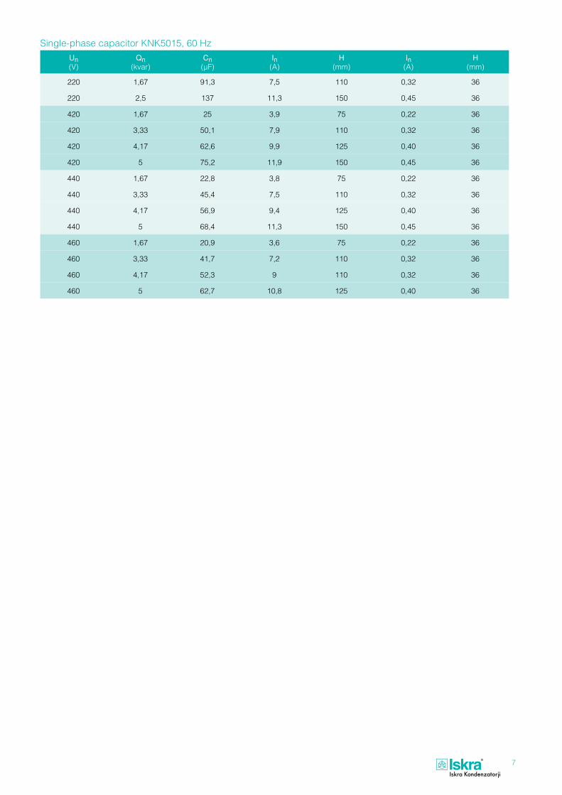
1.Single-phasecapacitorKNK5015
7
Un(V)
Qn(kvar)
Cn(µF)
In(A)
H(mm)
In(A)
H(mm)
220 1,67 91,3 7,5 110 0,32 36
220 2,5 137 11,3 150 0,45 36
420 1,67 25 3,9 75 0,22 36
420 3,33 50,1 7,9 110 0,32 36
420 4,17 62,6 9,9 125 0,40 36
420 5 75,2 11,9 150 0,45 36
440 1,67 22,8 3,8 75 0,22 36
440 3,33 45,4 7,5 110 0,32 36
440 4,17 56,9 9,4 125 0,40 36
440 5 68,4 11,3 150 0,45 36
460 1,67 20,9 3,6 75 0,22 36
460 3,33 41,7 7,2 110 0,32 36
460 4,17 52,3 9 110 0,32 36
460 5 62,7 10,8 125 0,40 36
Single-phase capacitor KNK5015, 60 Hz

8
2.Three-phasecapacitorsinaluminiumhousingtypeKNK5065
Ratedpower(kvar)
Ratedcapacitance(µF)
Ratedcurrent(A)
H(mm)
Weight(kg)
Packingunit(pcs)
2,5 3 × 16,6 3,6 145 0,45 36
3 3 × 19,9 4,3 145 0,45 36
4 3 × 26,5 5,8 185 0,55 36
5 3 × 33,2 7,2 185 0,55 36
Ratedpower(kvar)
Ratedcapacitance(µF)
Ratedcurrent(A)
H(mm)
Weight(kg)
Packingunit(pcs)
2,5 3 × 13,7 3,3 145 0,45 36
3 3 × 16,5 3,9 145 0,45 36
4 3 × 21,9 5,3 185 0,55 36
5 3 × 27,4 6,6 185 0,55 36
Ratedpower(kvar)
Ratedcapacitance(µF)
Ratedcurrent(A)
H(mm)
Weight(kg)
Packingunit(pcs)
2,5 3 × 12,5 3,1 145 0,45 36
3 3 × 15,0 3,7 145 0,45 36
4 3 × 20,0 5 185 0,55 36
5 3 × 25,1 6,3 185 0,55 36
Ratedpower(kvar)
Ratedcapacitance(µF)
Ratedcurrent(A)
H(mm)
Weight(kg)
Packingunit(pcs)
2,5 3 × 9,6 2,7 145 0,45 36
3 3 × 11,5 3,3 145 0,45 36
4 3 × 15,4 4,4 185 0,55 36
5 3 × 19,3 5,5 185 0,55 36
Rated voltage 400 V, 50 Hz
Rated voltage 440 V, 50 Hz
Rated voltage 460 V, 50 Hz
Rated voltage 525 V, 50 Hz
Figure 4

9
Figure 5
3.Three-phasecapacitorsinaluminiumhousingtypeKNK6049

10
Ratedvoltageandratedfrequency
Ratedpower(kvar)
Ratedcapacitance
(µF)
Ratedcurrentat50Hz
(A)
Ratedcurrentat60Hz
(A)
H
(mm)
Weight
(kg)
Packingunit
(pcs)
400 V50 Hz
10 3 × 66,3 14,4 - 220 1,35 16
12,5 3 × 83,3 18,0 - 260 1,60 16
15 3 × 100 21,7 - 260 1,60 16
20 3 × 133,0 28,9 - 325 1,90 16
25 3 × 165,8 36,1 - 370 2,20 16
420 V50 Hz
10 3 × 60,2 12,5 - 220 1,35 16
12,5 3 × 75,3 15,6 - 260 1,60 16
15 3 × 90,2 18,8 - 295 1,75 16
20 3 × 120,4 25,0 - 370 2,20 16
440 V 50 Hz400 V 60 Hz
10 3 × 54,8 13,1 14,4 220 1,35 16
12,5 3 × 68,5 16,4 18 260 1,60 16
15 3 × 82,5 19,7 21,7 295 1,75 16
20 3 × 109,7 26,2 26,2 370 2,20 16
25 3 × 137,1 32,8 36,1 370 2,20 16
460 V 50 Hz420 V 60 Hz
10 3 × 50,2 12,6 13,8 220 1,35 16
12,5 3 × 62,5 15,7 17,2 260 1,60 16
15 3 × 75,3 18,8 20,6 295 1,75 16
20 3 × 100,3 25,1 27,6 325 1,90 16
25 3 × 125,4 31,3 34,4 370 2,20 16
480 V 50 Hz440 V 60 Hz
10 3 × 46,1 12 13,1 220 1,35 16
12,5 3 × 57,7 15,1 16,4 260 1,60 16
15 3 × 69,1 18,1 19,7 295 1,75 16
20 3 × 92,1 24,1 26,2 370 2,20 16
500 V 50 Hz460 V 60 Hz
10 3 × 42,5 11,6 12,6 260 1,60 16
12,5 3 × 53,1 14,4 15,7 295 1,75 16
15 3 × 63,7 17,3 18,8 325 1,90 16
20 3 × 84,9 23,1 25,1 370 2,20 16
525 V 50 Hz480 V 60 Hz
10 3 × 38,5 11 12 260 1,60 16
12,5 3 × 48,1 13,8 15,1 295 1,75 16
15 3 × 57,7 16,5 18,1 325 1,90 16
20 3 × 77,0 22 24,1 370 2,20 16
25 3 × 96,2 27,5 30,1 370 2,20 16
Three-phase capacitors in aluminium cylindrical housing type KNK6049

11
Figure 6
4.Three-phasepowerfactorcorrectioncapacitorstypeKNK9053
TECHNICALDATA
Rated voltage Un: see table
Rated frequency: 50 Hz or 60 Hz
Capacitance tolerance: - 5 % to + 15 %
Losses: - dielectric - total
< 0,2 W/kvar < 0,5 W/kvar
Protection degree: IP 20
Discharge time : <‡ 3 min. to 75 V or less by discharge resistors
Standards: IEC Publ. 60831 - 1/2
Safety: self-healing, overpressure disconnector
Dielectric: metallized polypropylene film; sealed with plant oil, PCB-free
Permitted ambient temperature: - 25 °C to + 55 °C, other on request
Permitted storage temperature: - 40 °C to + 70 °C
Permitted overload: 1,1 × Un (8 h per day)1,3 × In (rated current)
In-rush current: 130 × In max.
Test conditions: between layers 2,15 × Un, AC, 2 s layers-housing 3,6 kV, AC, 2 s
Max. weight per kvar: cylindrical housing: 0,1 kg

12
Cn(µF)
Qn(kvar)
In(A)
Qn(kvar)
In(A)
Qn(kvar)
In(A)
H(mm)
FI(mm)
Weight(kg)
Packingunit
(pcs)
Un = 525 V Un = 525 V Un = 460 V Un = 440 V
3x38,5 10 11 7,7 9,7 7,0 9,2 205 90 1,35 16
3x48,2 12,5 13,8 9,6 12 8,8 11,5 240 90 1,60 16
3x57,8 15 16,5 11,5 14,4 10,5 13,8 240 90 1,60 16
3x77,0 20 22 15,3 19,2 14,0 18,4 205 116 1,90 9
3x96,3 25 27,5 19,2 24,1 17,6 23,1 240 116 2,20 9
Un = 460 V Un = 460 V Un = 440 V Un = 420 V
3x50,2 10 12,6 9,2 12,1 8,3 11,4 205 90 1,35 16
3x62,7 12,5 15,7 11,4 15 10,4 14,3 205 90 1,35 16
3x75,2 15 18,8 13,7 18 12,5 17,2 240 90 1,60 16
3x100,3 20 25,1 18,3 24 16,7 23 205 116 1,90 9
3x125,4 25 31,3 22,9 30 20,8 28,6 240 116 2,20 9
Un = 440 V Un = 440 V Un = 420 V Un = 400 V
3x54,9 10 13,1 9,1 12,5 8,3 12 205 90 1,35 16
3x68,6 12,5 16,4 11,5 15,8 10,4 15 205 90 1,35 16
3x82,3 15 19,7 13,7 18,8 12,4 17,9 240 90 1,60 16
3x110,0 20 26,2 18,3 25,2 16,6 24 205 116 1,90 9
3x137,1 25 32,8 22,8 31,3 20,7 29,9 240 116 2,20 9
Un = 420 V Un = 420 V Un = 400 V Un = 380 V
3x60,2 10 13,7 9,1 13,1 8,2 12,5 205 90 1,35 16
3x75,2 12,5 17,2 11,3 16,3 10,2 15,5 240 90 1,60 16
3x90,3 15 20,6 13,6 19,6 12,3 18,7 240 90 1,60 16
3x120,3 20 27,5 18,1 26,1 16,4 24,9 205 116 1,90 9
3x150,4 25 34,4 22,7 31,2 20,5 28,2 240 116 2,20 9
Un = 400 V Un = 400 V Un = 380 V
3x66,3 10 14,4 9,0 13,7 205 90 1,35 16
3x83,3 12,5 18 11,3 17,2 205 90 1,35 16
3x100 15 21,7 13,6 20,7 240 90 1,60 16
3x133 20 28,9 18,1 27,5 205 116 1,90 9
3x165,8 25 36,1 22,6 34,3 240 116 2,20 9
Three-phase capacitors in aluminium cylindrical housing type KNK9053 (fn = 50 Hz)

13
Cn(µF)
Qn(kvar)
In(A)
Qn(kvar)
In(A)
Qn(kvar)
In(A)
H(mm)
FI(mm)
Weight(kg)
Packingunit
(pcs)
Un = 525 V Un = 525 V Un = 460 V Un = 440 V
3x32,1 10 11 7,7 9,7 7,0 9,2 205 90 1,35 16
3x40,1 12,5 13,8 9,6 12 8,8 11,5 205 90 1,35 16
3x48,1 15 16,5 11,5 14,4 10,5 13,8 240 90 1,60 16
3x64,2 20 22 15,3 19,2 14,0 18,4 205 116 1,90 9
3x80,2 25 27,5 19,2 24,1 17,6 23,1 240 116 2,20 9
Un = 460 V Un = 460 V Un = 440 V Un = 420 V
3x41,8 10 12,6 9,2 12,1 8,3 11,4 160 90 1,05 16
3x52,2 12,5 15,7 11,4 15 10,4 14,3 205 90 1,35 16
3x62,7 15 18,8 13,7 18 12,5 17,2 205 90 1,35 16
3x83,6 20 25,1 18,3 24 16,7 23 240 90 1,60 16
3x104,5 25 31,3 22,9 30 20,8 28,6 205 116 1,90 9
Un = 440 V Un = 440 V Un = 420 V Un = 400 V
3x45,7 10 13,1 9,1 12,5 8,3 12 160 90 1,05 16
3x57,1 12,5 16,4 11,5 15,8 10,4 15 205 90 1,35 16
3x68,5 15 19,7 13,7 18,8 12,4 17,9 205 90 1,35 16
3x91,3 20 26,2 18,3 25,2 16,6 24 240 90 1,60 16
3x114,2 25 32,8 22,8 31,3 20,7 29,9 205 116 1,90 9
Un = 420 V Un = 420 V Un = 400 V Un = 380 V
3x50,1 10 13,7 9,1 13,1 8,2 12,5 205 90 1,35 16
3x62,6 12,5 17,2 11,3 16,3 10,2 15,5 205 90 1,35 16
3x75,2 15 20,6 13,6 19,6 12,3 18,7 240 90 1,60 16
3x100,2 20 27,5 18,1 26,1 16,4 24,9 205 116 1,90 9
3x125,3 25 34,4 22,6 32,6 20,4 31,0 240 116 2,20 9
Un = 400 V Un = 400 V Un = 380 V
3x55,3 10 14,4 9,0 13,7 160 90 1,05 16
3x69,7 12,5 18 11,3 17,2 205 90 1,35 16
3x82,9 15 21,7 13,6 20,7 205 90 1,35 16
3x110,5 20 28,9 18,1 27,5 240 90 1,60 16
3x138,2 25 36,1 22,6 34,3 205 116 1,90 9
Three-phase capacitors in aluminium cylindrical housing type KNK9053 (fn = 60Hz)

14
Figure 7
5.Three-phasecapacitorsKNK9103andKNK9143

15
Un(V)
Qn(kvar)
Cn(µF)
In(A)
A(mm)
A’(mm)
B(mm)
DWeight
KNK9103(kg)
WeightKNK9143
(kg)
230 5 3 × 100,3 12,5 190 190 70 M 8 3,65 6,40
230 10 3 × 200,7 25,1 380 190 70 M 8 5,65 7,30
230 12,5 3 × 250,7 31,1 380 190 70 M 8 5,95 7,80
230 15 3 × 301,0 37,6 380 380 140 M 12 8,30 12,40
230 20 3 × 401,2 50,2 380 380 140 M 12 9,65 13,20
230 25 3 × 501,5 62,7 380 380 140 M 12 10,25 13,80
400 5 3 × 33,2 7,2 190 190 70 M 8 2,95 6,00
400 7,5 3 × 49,7 10,8 190 190 70 M 8 3,05 6,10
400 10 3 × 66,3 14,4 190 190 70 M 8 3,25 6,25
400 12,5 3 × 82,9 18 190 190 70 M 8 3,30 6,30
400 15 3 × 99,5 21,7 190 190 70 M 8 3,65 6,45
400 20 3 × 132,6 28,9 380 190 70 M 8 5,65 7,30
400 25 3 × 165,8 36,1 380 190 70 M 8 5,95 7,80
400 30 3 × 198,9 43,3 380 190 70 M 8 6,25 8,10
400 40 3 × 265,3 57,7 380 380 140 M 12 8,30 12,20
400 50 3 × 331,6 72,2 380 380 140 M 12 9,65 13,20
400 60 3 × 397,9 86,6 380 380 140 M 12 10,25 13,80
415 5 3 × 30,8 7 190 190 70 M 8 2,95 6,10
415 7,5 3 × 46,2 10,4 190 190 70 M 8 3,05 6,25
415 10 3 × 61,6 13,9 190 190 70 M 8 3,25 6,30
415 12,5 3 × 77,0 17,4 190 190 70 M 8 3,30 6,45
415 15 3 × 92,4 20,9 380 190 70 M 8 3,65 7,30
415 20 3 × 123,2 27,8 380 190 70 M 8 5,65 7,80
415 25 3 × 154,0 34,8 380 190 70 M 8 5,95 8,10
415 30 3 × 184,0 41,7 380 190 70 M 8 6,25 8,40
415 40 3 × 246,4 55,7 380 380 140 M 12 8,30 12,20
415 50 3 × 308,0 69,6 380 380 140 M 12 9,65 13,20
440 5 3 × 27,4 6,5 190 190 70 M 8 2,95 6,00
440 7,5 3 × 41,1 9,8 190 190 70 M 8 3,05 6,10
440 10 3 × 54,8 13,1 190 190 70 M 8 3,25 6,25
440 12,5 3 × 68,5 16,4 190 190 70 M 8 3,30 6,30
440 15 3 × 82,2 19,7 190 190 70 M 8 3,65 6,45
440 20 3 × 109,6 26,3 380 190 70 M 8 3,65 7,30
440 25 3 × 137,0 32,8 380 190 70 M 8 5,95 7,80
440 30 3 × 164,4 39,4 380 190 70 M 8 6,25 8,10
440 40 3 × 219,2 52,6 380 380 140 M 12 8,30 12,20
440 50 3 × 272,0 65,6 380 380 140 M 12 9,65 13,20
440 60 3 × 328,8 78,8 380 380 140 M 12 10,25 13,80
Three-phase capacitors KNK9103 and KNK9143, 50 Hz

16
Un(50Hz)(V)
Qn(kvar)
Cn(µF)
In(A)
A(mm)
A’(mm)
B(mm)
DWeight
KNK9103(kg)
WeightKNK9143
(kg)
460 5 3 × 25,0 6,2 190 190 70 M 8 2,95 6,00
460 7.5 3 × 37,6 9,4 190 190 70 M 8 3,05 6,10
460 10 3 × 50,1 12,5 190 190 70 M 8 3,25 6,25
460 12.5 3 × 62,6 15,6 190 190 70 M 8 3,30 6,30
460 15 3 × 75,2 18,8 190 190 70 M 8 3,65 6,45
460 20 3 × 100,2 25,1 380 190 70 M 8 5,65 7,30
460 25 3 × 125,3 31,3 380 190 70 M 8 5,95 7,80
460 30 3 × 150,3 37,6 380 190 70 M 8 6,25 8,10
460 40 3 × 200,5 50,2 380 380 140 M 12 8,30 12,20
460 50 3 × 250,6 62,7 380 380 140 M 12 9,65 13,20
460 60 3 × 300,6 75,3 380 380 140 M 12 10,25 13,80
525 5 3 × 19,3 5,5 190 190 70 M 8 2,95 6,10
525 7.5 3 × 28,9 8,2 190 190 70 M 8 3,05 6,25
525 10 3 × 39,0 11 190 190 70 M 8 3,25 6,30
525 12.5 3 × 48,1 13,8 190 190 70 M 8 3,30 6,45
525 15 3 × 57,7 16,5 190 190 70 M 8 3,65 7,30
525 20 3 × 77,0 22 380 190 70 M 8 5,65 7,80
525 25 3 × 92,2 27,5 380 190 70 M 8 5,95 8,10
525 30 3 × 115,5 33 380 380 140 M 12 6,25 12,20
525 40 3 × 154,0 44 380 380 140 M 12 8,30 13,20
525 50 3 × 192,5 55 380 380 140 M 12 9,65 13,80
550 5 3 × 19,3 5,2 190 190 70 M 8 2,95 6,00
550 7.5 3 × 26,3 7,8 190 190 70 M 8 3,05 6,10
550 10 3 × 35,0 10,5 190 190 70 M 8 3,25 6,25
550 12.5 3 × 43,7 13,1 190 190 70 M 8 3,30 6,30
550 15 3 × 52,5 15,7 190 190 70 M 8 3,65 6,45
550 20 3 × 70,1 20,9 380 190 70 M 8 5,65 7,30
550 25 3 × 87,5 26,2 380 190 70 M 8 5,95 7,80
550 30 3 × 105,0 31,5 380 190 70 M 8 6,25 8,10
550 40 3 × 140,2 41,9 380 380 140 M 12 8,30 12,20
550 50 3 × 175,0 52,5 380 380 140 M 12 9,65 13,2
550 60 3 × 210,3 63 380 380 140 M 12 10,25 13,8
Three-phase capacitors KNK9103 and KNK9143, 50 Hz

17
Un(50Hz)(V)
Qn(kvar)
Cn(µF)
In(A)
A(mm)
A’(mm)
B(mm)
DWeight
KNK9103(kg)
WeightKNK9143
(kg)
220 5 3 × 91,3 13.13 190 190 70 M 8 3,65 6,40
220 10 3 × 182,6 26,27 380 190 70 M 8 5,95 7,30
220 15 3 × 273,9 39,41 380 190 70 M 8 6,25 7,75
220 20 3 × 365,2 52,54 380 380 140 M 12 8,30 12,10
220 25 3 × 456,5 65,68 380 380 140 M 12 9,65 13,10
220 30 3 × 547,8 78,82 380 380 140 M 12 10,25 13,70
420 5 3 × 25,0 6,88 190 190 70 M 8 2,95 6,10
420 10 3 × 50,1 13,7 190 190 70 M 8 3,25 6,20
420 15 3 × 75,2 20,64 190 190 70 M 8 3,65 6,40
420 20 3 × 100,2 27,5 380 190 70 M 8 5,65 7,25
420 25 3 × 125,3 34,4 380 190 70 M 8 5,95 7,70
420 30 3 × 150,4 41,28 380 190 70 M 8 6,25 8,00
420 50 3 × 250,6 68,8 380 380 140 M 12 9,65 13,10
420 60 3 × 300,8 82,57 380 380 140 M 12 10,25 13,70
440 5 3 × 22,8 6,5 190 190 70 M 8 2,95 6,10
440 10 3 × 45,7 13,1 190 190 70 M 8 3,25 6,20
440 15 3 × 68,5 19,6 190 190 70 M 8 3,65 6,40
440 20 3 × 91,3 26 380 190 70 M 8 5,65 7,25
440 25 3 × 114,2 32,8 380 190 70 M 8 5,95 7,70
440 30 3 × 137,0 39,4 380 190 70 M 8 6,25 8,00
440 50 3 × 228,4 65,6 380 380 140 M 12 9,65 13,10
440 60 3 × 274,0 78,7 380 380 140 M 12 10,25 13,70
460 5 3 × 20,8 6,3 190 190 70 M 8 2,95 6,10
460 10 3 × 41,6 12,6 190 190 70 M 8 3,25 6,20
460 15 3 × 62,2 18,9 190 190 70 M 8 3,65 6,40
460 20 3 × 83,2 25,2 380 190 70 M 8 5,65 7,25
460 25 3 × 104,3 31,5 380 190 70 M 8 5,95 7,70
460 30 3 × 125,2 37,8 380 190 70 M 8 6,25 8,00
460 50 3 × 208,6 63 380 380 140 M 12 9,65 13,10
460 60 3 × 250,7 75,3 380 380 140 M 12 10,25 13,70
Three-phase capacitors KNK9103 and KNK9143, 60 Hz

18
Figure 86.Single-phasecapacitorsKNK9101andKNK9141

19
Un(V)
Qn(kvar)
Cn(µF)
In(A)
A(mm)
A’(mm)
B(mm)
DWeight
KNK9101(kg)
WeightKNK9141
(kg)
230 5 300,9 21,7 190 190 70 M 8 3,60 6,40
230 7,5 450,6 32,6 380 190 70 M 8 5,30 7,25
230 10 602,1 43,4 380 190 70 M 8 5,60 7,70
230 12.5 752,1 54,3 380 190 70 M 8 5,90 8,00
230 15 903 65,2 380 380 140 M 12 8,25 12,10
230 20 1203,6 86,9 380 380 140 M 12 9,60 13,10
230 25 1504,4 108,6 380 380 140 M 12 10,20 13,70
400 5 99,5 12,5 190 190 70 M 8 2,90 5,90
400 7,5 149,1 18,7 190 190 70 M 8 3,00 6,00
400 10 198,8 25 190 190 70 M 8 3,20 6,10
400 12,5 248,5 31,2 190 190 70 M 8 3,25 6,20
400 15 298,2 37,5 190 190 70 M 8 3,60 6,40
400 20 397,6 50 380 190 70 M 8 5,60 7,25
400 25 497 62,5 380 190 70 M 8 5,90 7,70
400 30 596,4 75 380 190 70 M 8 6,25 8,00
400 40 795,2 100 380 380 140 M 12 8,25 12,10
400 50 994 125 380 380 140 M 12 9,60 13,10
550 5 52,5 9,1 190 190 70 M 8 2,90 5,90
550 7,5 78,7 13,.6 190 190 70 M 8 3,00 6,00
550 10 105 18,1 190 190 70 M 8 3,20 6,10
550 12,5 131,2 22,7 190 190 70 M 8 3,25 6,20
550 15 157,5 27,2 190 190 70 M 8 3,60 6,40
550 20 210 36,3 380 190 70 M 8 5,60 7,25
550 25 262,5 45,4 380 190 70 M 8 5,90 7,70
550 30 315 54,5 380 190 70 M 8 6,25 8,00
550 40 420 72,7 380 380 140 M 12 8,25 12,10
550 50 525 90,9 380 380 140 M 12 9,60 13,10
550 60 630 109,1 380 380 140 M 12 10,20 13,70
Single-phase capacitors KNK9101 and KNK9141, 50 Hz

20
Ratedpowerofmotor
(kW)
Powerratingsofcapacitorin(kvar)withrespecttomotorpower,speedofrotationandload
3000 rev/min 1500 rev/min 1000 rev/min 750 rev/min 500 rev/min
Noload Fullload Noload Fullload Noload Fullload Noload Fullload Noload Fullload
5,5 2,2 2,9 2,4 3,3 2,7 3,6 3,2 4,3 4 5,2
7,5 3,4 4,4 3,6 4,8 4,1 5,4 4,6 6,1 5,5 7,2
11 5 6,5 5,5 7,2 6 8 7 9 7.5 10
15 6,5 8,5 7 9,5 8 10 9 12 10 13
18,5 8 11 9 12 10 13 11 15 12 16
22 10 12,5 11 13,5 12 15 13 16 15 19
30 14 18 15 20 17 22 22 25 22 28
37 18 24 20 27 22 30 26 34 29 39
45 19 28 21 31 24 34 28 38 31 43
55 22 34 25 37 28 41 32 46 36 52
75 28 45 32 49 37 54 41 60 45 68
90 34 54 39 59 44 65 49 72 54 83
110 40 64 46 70 52 76 58 85 63 98
132 45 72 53 80 60 87 67 97 75 110
160 54 86 64 96 72 103 81 116 91 132
200 66 103 77 115 87 125 97 140 110 160
250 75 115 85 125 95 137 105 150 120 175
1. Capacitor power ratings for individual compensation of motors (reference values)
The required capacitor power is calculated with the formula:
Qn = 0,9 · Un · lmag. · √ 3
where:
Qn - is rated capacitor power (kvar)
Un - is rated motor voltage (kV)
Imag - is motor magnetising current (A)
Instructions for the selection of capacitor power, cross-section of supply cables, fuse ratings and bases are given for determining the individual compensation of reactive power of motors and transformers.
The following tables show the reference values needed in dependence of their power.
Recommended cross-section of supply cables, fuse ratings and bases are also given in dependence of capacitor phase currents.
Basic of power factor correction
21
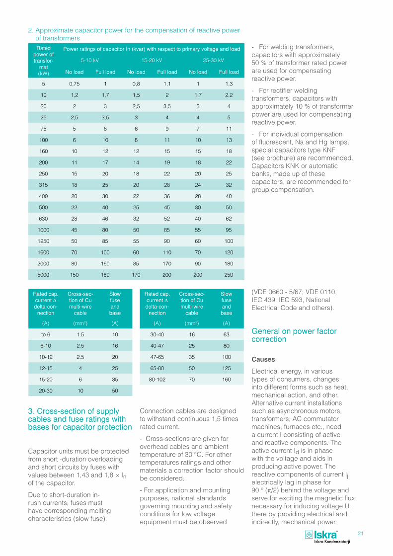
Ratedpoweroftransfor-
mat(kW)
PowerratingsofcapacitorIn(kvar)withrespecttoprimaryvoltageandload
5-10 kV 15-20 kV 25-30 kV
Noload Fullload Noload Fullload Noload Fullload
5 0,75 1 0,8 1,1 1 1,3
10 1,2 1,7 1,5 2 1,7 2,2
20 2 3 2,5 3,5 3 4
25 2,5 3,5 3 4 4 5
75 5 8 6 9 7 11
100 6 10 8 11 10 13
160 10 12 12 15 15 18
200 11 17 14 19 18 22
250 15 20 18 22 20 25
315 18 25 20 28 24 32
400 20 30 22 36 28 40
500 22 40 25 45 30 50
630 28 46 32 52 40 62
1000 45 80 50 85 55 95
1250 50 85 55 90 60 100
1600 70 100 60 110 70 120
2000 80 160 85 170 90 180
5000 150 180 170 200 200 250
Ratedcap.currentΔdelta-con-nection
Cross-sec-tionofCumulti-wirecable
Slowfuseandbase
(A) (mm2) (A)
30-40 16 63
40-47 25 80
47-65 35 100
65-80 50 125
80-102 70 160
Ratedcap.currentΔdelta-con-nection
Cross-sec-tionofCumulti-wirecable
Slowfuseandbase
(A) (mm2) (A)
to 6 1.5 10
6-10 2.5 16
10-12 2.5 20
12-15 4 25
15-20 6 35
20-30 10 50
2. Approximate capacitor power for the compensation of reactive power of transformers
- For welding transformers, capacitors with approximately 50 % of transformer rated power are used for compensating reactive power.
- For rectifier welding transformers, capacitors with approximately 10 % of transformer power are used for compensating reactive power.
- For individual compensation of fluorescent, Na and Hg lamps, special capacitors type KNF (see brochure) are recommended. Capacitors KNK or automatic banks, made up of these capacitors, are recommended for group compensation.
3.Cross-sectionofsupplycablesandfuseratingswithbasesforcapacitorprotection
Capacitor units must be protected from short -duration overloading and short circuits by fuses with values between 1,43 and 1,8 × In of the capacitor.
Due to short-duration in-rush currents, fuses must have corresponding melting characteristics (slow fuse).
Connection cables are designed to withstand continuous 1,5 times rated current.
- Cross-sections are given for overhead cables and ambient temperature of 30 °C. For other temperatures ratings and other materials a correction factor should be considered.
- For application and mounting purposes, national standards governing mounting and safety conditions for low voltage equipment must be observed
(VDE 0660 - 5/67; VDE 0110, IEC 439, IEC 593, National Electrical Code and others).
Generalonpowerfactorcorrection
Causes
Electrical energy, in various types of consumers, changes into different forms such as heat, mechanical action, and other. Alternative current installations such as asynchronous motors, transformers, AC commutator machines, furnaces etc., need a current I consisting of active and reactive components. The active current Id is in phase with the voltage and aids in producing active power. The reactive components of current lj electrically lag in phase for 90 ° (π/2) behind the voltage and serve for exciting the magnetic flux necessary for inducing voltage Ui there by providing electrical and indirectly, mechanical power.

22
This can be illustrated by a substitute circuit with ohmic and inductive resistance connected in parallel. The diagram illustrates the apparent current I which is the geometric sum of the active Id and reactive current lj. This current lags behind the applied voltage for and angle ϕ.
The greater the number of consumers connected to the network, the greather the phase shift which however, is unwanted since it conditions the following expressions for the working, the reactive, and the apparent power (e.g. in three-phase systems):
P = √ 3 · U · Id
= √ 3 · U · I · cosϕ 10-3 (kW)
Q = √ 3 · U · Ij
= √ 3 · U · I · sinϕ 10-3 (kvar)
S = √ 3 · U · I = √ 3 · U · I · 10-3
(kVA)
Id P cosϕ = — = —...is the power factor I S
The diagram with parallel connection of ohmic and inductive resistance is not sufficient when dealing with the above mentioned equipment, since the appearance of stray magnetic flux (which is wanted only in certain specific cases) cannot be prevented in practice.
Due to flux, the AC equipment demonstrates series inductive resistance at the same time, which provides a substitute circuit and the diagram in figure 9.
In equipment with parallel resistances the reactive power is the product of the magnetizing current Ij and the applied voltage, whereas in equipment with resistances connected in series it is the product of the apparent current I and inductive voltage drop Uj.
Both types of equipment require reactive power and are the cause of electrical power factor reduction in the network.
Theresultsofsuchacondition
1. Electric power stations supplying large numbers of inductive and ohmic consumers must supply the necessary apparent power. Power lines must be designed to carry higher powers than needed for active power. For a certain constant active power the apparent power increases with the increase of reactive power according to the formula: P S =
cosϕ
Ideal for transmission would be when cosϕ = 1, since the power station would then supply pure
UQj
UQdUQ
U
U1
Ud
Id
U2
Uj
ULj
UL
ULd
I
Ij
~3G
XX
L
L
RR
UQj
UQdUQ
U
U1
Ud
Id
U2
Uj
ULj
UL
ULd
I
Ij
~3G
XX
L
L
RR
Figure 9 Figure 10 active power.
2. Electric power transmission brings about loss, which increases as a function of the length of a transmission line and of the power factor.
To explain this, let us take that a consumer operates with a cosϕ = 0,7 x (Id = Ij).
Apparent power is:
I = √ Id2 + Ij2 = Id √ 2 Joul losses increase two times at transmission of such power with regard to power transmission at cosϕ = 1:
Pizg = I2 · R = 2 · Id2 · R 3. With long transmission lines voltage drop increases remarkably i.e. the inductive part more than the ohmic. Increasing the conductor cross-section therefore, does not solve the problem. The only solution is to improve cosϕ.
Howtoimprovesuchunfavourableconditions?
The reactive power needed can be produced by employing suitable capacitors connected in parallel relieving, thereby, production and transmission of electrical power.
The functioning of capacitors producing electrical power, can be explained as follows.
It is known that a magnetic field in non-corrected networks is excited and made to disappear by a pulsating magnetizing current. A suitable capacitor is connected in parallel to a consumer of reactive power, which at the disappearance of the electromagnetic field, collects the released energy and uses this for exciting its own electro-static field (dielectric charging).
Immediately after, in the rhythm of the alternating current, the capacitor at the disappearance of the electrostatic field provides the released power for exciting the electromagnetic field with hardly any loss (dielectric discharge).

23
This released energy oscillates with double network frequency between the power station and the electrical energy consumer. In this way, the capacitor covers the needs for reactive power of the inductive in parallel connected consumers.
The capacitor therefore, relieves production and transmission of reactive power by its correction. The diagram illustrates the ideal functioning of correction.
QCQC1,
S
SS
U
1
1
P
P
Q j1 Q j
Advantagesofpowerfactorcorrection
1. By incorporating a power factor system at the consumers end the power station is relieved from supplying reactive power and can therefore, use its full capacity for producing useful active energy.
2. Transmission lines are freed of reactive power, Joul losses largely decrease as XL→ 0 and cosϕ approaches the ideal value 1. This relief in the existing plant enables connection of new consumers.
3. Voltage drop at the end of transmission lines largely decreases:
U = I · X · sinϕ + I · R · sinϕ
U = Ij · X + Id · R
sinϕ → 0 therefore:
U = Id · R
4. Rolling-mills and electrochemical plants are large consumers of reactive power while at the same time being the originators of higher harmonics. The following dual effect can be obtained by proper combination of capacitors and chokes:
- correction of internal plant network and
- removal of higher harmonics from internal plant network.
5. Reactive power is produced on the spot (consumer centre) by a capacitor bank, therefore, eliminating payment of excessive reactive power consumption. This in turn increases factor net profit and releases financial funds for other usage.
Higher harmonics present in networks are caused by over saturated transformers, especially rectifiers. Factories using such equipment are at the same time the main originators of higher harmonics and the largest consumers of reactive power, initiating therefore the need for correction.
The problem of overloading of capacitors, or even the appearance of resonance arising with correction, can be solved by adding, in series with the capacitors, a special choke tuned to the harmful higher harmonics. The use of low-loss chokes adds to the plant costs, but provides the following two important advantages:
a) Impedance traps relieve the supply networks of higher harmonics. Problems arising from the controlling of rectifier equipment are eliminated especially at parallel operation.
Above all, conditions causing resonance, which in turn cause overloading of capacitor banks, are eliminated.
b) Capacitors in an impedance trap correct the reactive power of the fundamental wave and reduce electric power expenses.
Methodsofpowerfactorcorrection
Three types should be distinguished:
- individual correction
- group correction and
- central correction
Individualcorrection
This is especially practicable where larger motors are operated continuously throughout the day such as: pumps, compressors etc. Power -factor correction is possible, without the need of automatic control, up to as high as cosϕk= 0,95.
Advantages:
- reactive power is corrected at its origin so that the supply cables are not loaded unnecessarily
- no additional switches and fuses are required since both the electric motor and the capacitor are actuated by a common switch.
The power of a capacitor connected in parallel to the electric motor is calculated by the formula:
Qc = √3 · 0,9 · Io · Un · 10-3 (kvar)
or approximately by using the diagram in figure 12.
Attention has to be paid to the following:
1. Motors started with star delta switches must not be directly connected since the switch-over action momentarily switches off the capacitor. Immediate connection of the capacitor is not permitted.
2. With over current or thermal motor protection, current reduction (correction) must be considered.
3. With engines having high torque, care must be taken to prevent over-excitation.
Figure 11
Figure 12

24
Groupcorrection
A single capacitor bank or power correction equipment can be employed for a large group of small inductive consumers of electric power. The method is especially applicable for groups of small motors.
Usually consumption of reactive power of such a group is extremely variable, therefore, the bank is divided into several stages. In order to rate such stages properly, a daily operating diagram should be drawn up.
Centralcorrection
A group correction system for a complete plant is connected directly to the main busbars. Use is made of automatic control in order to gain a high cosϕ >_ 0,95 and to reduce the number of staff.
Best results are obtained by combining all three methods of power factor correction, and adapting them to the individual operating conditions.
Determinationofpowerinpowerfactorcorrectionequipment
The power of a power factor correction unit depends on the amount of reactive power, i.e. the kvar figure to be corrected for every hour. Usually a monthly power settlement is available. Since, large consumers of reactive power are granted 32,9 % (cosϕ = 0,95) of active power free of charge, excessive reactive power, which has to be paid for, can be calculated and corrected.
The monthly settlement contains the following information:
Av = active power-high tariff
An = active power-low tariff
Wv = reactive power-high tariff
Wn = reactive power-low tariff
Pmax = peak loading-15 minutes
Necessary power of power correction equipment:
Qc = Psr (tgϕ1 - tgϕ2)
cosϕ2 = cosϕk = 0,95
Av + An
Psr = ———— T
Wv + Wn
tgϕ1 = ————
Av + An
T = number of operating hours per month.
For values see tables 1 and 2.
Calculationexample
Monthly balance of electrical power consumer:
Av = 150.000 kWh
An = 100.000 kWh
Wv = 160.000 kvarh
Wn = 100.000 kvarh
T = 200 h
Necessary power of power correction equipment:
Av + An 150,000 + 100,000 Psr = ———— = ———————— T 200
Psr = 1250 kW
Wv + Wn
tgϕ1 = ————
Av + An
160,000 + 100,000 tgϕ1 = ————————— = 1,04
150,000 + 100,000
Qc = 1250 (1,040 - 0,329) = 890 kvar
The same calculation can be illustrated by a diagram as in figure 13.
Figure 13
Figure 14

25
cosϕ tgϕ sinϕ cosϕ tgϕ sinϕ
1 0 0 0,73 0,936 0,683
0,99 0,142 0,141 0,72 0,964 0,694
0,99 0,142 0,141 0,72 0,964 0,694
0,98 0,203 0,199 0,71 0,992 0,704
0,97 0,251 0,243 0,7 1,02 0,714
0,96 0,292 0,28 0,69 1,049 0,724
0,95 0,329 0,312 0,68 1,078 0,733
0,94 0,363 0,341 0,67 1,108 0,742
0,93 0,395 0,368 0,66 1,138 0,751
0,92 0,426 0,392 0,65 1,169 0,76
0,91 0,456 0,415 0,64 1,201 0,768
0,9 0,484 0,436 0,63 1,233 0,777
0,89 0,512 0,456 0,62 1,265 0,785
0,88 0,54 0,457 0,61 1,299 0,792
0,87 0,567 0,493 0,6 1,333 0,8
0,86 0,593 0,51 0,59 1,368 0,807
0,85 0,62 0,527 0,58 1,405 0,815
0,84 0,646 0,543 0,57 1,441 0,822
0,83 0,672 0,558 0,56 1,479 0,828
0,82 0,698 0,572 0,55 1,518 0,835
0,81 0,724 0,586 0,54 1,559 0,842
0,8 0,75 0,6 0,53 1,6 0,848
0,79 0,776 0,613 0,52 1,643 0,854
0,78 0,802 0,626 0,51 1,687 0,86
0,77 0,829 0,638 0,5 1,732 0,866
0,76 0,855 0,65
0,75 0,882 0,661
0,74 0,909 0,673
Table1

26
Actualpowerfactorcosϕ2
Requiredpowerfactorcosϕ2
0,7 0,75 0,8 0,82 0,84 0,86 0,88 0,9 0,92 0,94 0,96 0,98 1
0,5 0.71 0,85 0,98 1,03 1,09 1,14 1,19 1,25 1,31 1,37 1,44 1,53 1,73
0,52 0,62 0,76 0,89 0,94 1 1,05 1,1 1,16 1,22 1,28 1,35 1,44 1,64
0,54 0,54 0,68 0,81 0,86 0,91 0,97 1,02 1,07 1,13 1,2 1,27 1,36 1,56
0,56 0,46 0,6 0,73 0,78 0,83 0,89 0,94 1 1,05 1,12 1,19 1,28 1,48
0,58 0,38 0,52 0,65 0,71 0,76 0,81 0,86 0,92 0,98 1,04 1,11 1,2 1,4
0,6 0,31 0,45 0,58 0,64 0,69 0,74 0,79 0,85 0,91 0,97 1,04 1,13 1,33
0,62 0,25 0,38 0,52 0,57 0,62 0,67 0,73 0,78 0,84 0,9 0,97 1,06 1,27
0,64 0,18 0,32 0,45 0,5 0,55 0,61 0,66 0,72 0,77 0,84 0,91 1 1,2
0,66 0,12 0,26 0,39 0,44 0,49 0,54 0,6 0,65 0,71 0,78 0,85 0,94 1,14
0,68 0,06 0,2 0,33 0,38 0,43 0,48 0,54 0,59 0,65 0,72 0,79 0,88 1,08
0,7 0,14 0,27 0,32 0,37 0,43 0,48 0,54 0,59 0,66 0,73 0,82 1,02
0,72 0,08 0,21 0,27 0,32 0,37 0,42 0,48 0,54 0,6 0,67 0,76 0,96
0,74 0,03 0,16 0,21 0,26 0,32 0,37 0,42 0,48 0,55 0,62 0,71 0,91
0,76 0,11 0,16 0,21 0,26 0,32 0,37 0,43 0,49 0,56 0,65 0,86
0,78 0,05 0,1 0,16 0,21 0,26 0,32 0,38 0,44 0,51 0,6 0,8
0,8 0,05 0,1 0,16 0,21 0,27 0,32 0,39 0,46 0,55 0,75
0,82 0,05 0,1 0,16 0,21 0,27 0,34 0,41 0,49 0,7
0,84 0,05 0,11 0,16 0,22 0,28 0,35 0,44 0,65
0,86 0,05 0,11 0,17 0,23 0,3 0,39 0,59
0,88 0,06 0,11 0,18 0,25 0,34 0,54
0,9 0,06 0,12 0,19 0,28 0,48
0,92 0,06 0,13 0,22 0,43
0,94 0,07 0,16 0,36
Table2
Productionprogramme
Capacitors for electronics
- polyester foil
- polypropylene foil
Capacitors and filters for radio interference suppression
Motor running & motor starting capacitors
Lamp capacitors
Capacitors for power electronics
Power factor capacitors
Automatic power factor banks
Induction heating capacitors
Electronic regulators for power factor banks
Tools and production machines

W11
Iskra Kondenzatorji, d. d.
Vajdova ulica 71
SI-8333 SemiË, Slovenia
Phone: +386 7 38 49 200
+386 7 38 49 275 - Sales Department
Fax: +386 7 30 67 110, 30 67 609
E-mail: [email protected]
http://www.iskra-capacitors.com
Ljubljana
Novo mesto
SemiË Metlika
Crnomelj
Maribor
Jesenice
Koper
CeljeSlovenia
CRO
HA
I