low voltage motor protection
TRANSCRIPT

Low Voltage Motor Protection
William Martin, Amanda Eason, and Ashwinkumar Govinbhai Patel
In today's world of manufacturing, motors provide the majority of power that is used to convert raw materials into finished goods. In fact, over 50% of the work completed in today's manufacturing plant is completed by electric motors. It is estimated that this percentage will continue to increase for the foreseeable future. With this great percentage of manufacturing capability relying on electric motors, it is important to ensure that motors and their circuits are properly protected to provide maximum operating time and minimum downtime. Improperly protected motors/circuits in today's modern manufacturing plants can mean production downtime losses from hundreds of dollars to tens of thousands of dollars per hour besides the cost of in-process material that can be destroyed. It is no wonder that over the last several years, an enormous amount of effort and resources has been used by control manufacturers in the development of improved and cost-effective short-circuit protection and overload protection devices.
This paper addresses many issues related to the proper understanding of short-circuit and overload protection devices and how to select them. This paper covers the following subjects:
• Electrical code requirements
• Basics of motor protection circuit breakers
• Basics of overload protection devices
– Thermal overload relays (bimetallic and eutectic alloy)
– Electronic overload relays
• Advanced motor protection
• Life of a typical motor installation
• Terminology

2
Code Requirements
Whether you are designing motor circuits for use in North America, Europe, or any other part of the world, several basic requirements are typically specified for a motor circuit. In the Unites States, the National Electrical Code (NEC) is followed as the basis for most electrical installations. In Canada, the Canadian Electrical Code (CEC) is followed, and in Europe, each country has its own electrical code requirements that must be met. Due to time and space limitations, we will address code issues in reference to the NEC unless otherwise stated.
Article 430 of the NEC describes the requirements for installations involving motors, motor circuits, and controllers. In Article 430, the requirements for motor branch circuit short-circuit, ground fault protection, and motor overload protection are specified. Figure 1 identifies the control and protection components required for a motor branch circuit.
Figure 1 - NEC Article 430 Motor Branch Circuit Requirements
Now that we have identified the components required by code to provide motor branch circuit protection, let's take a closer look at the available types of overload protection devices that will meet code requirements.
Motor Protection Circuit Breakers
Motor Protection Circuit Breakers (MPCBs) combine the short-circuit and isolation functionality of a molded case circuit breaker with the motor overcurrent protection of a traditional overload relay. These devices are traditionally used in two-component starter applications, with a contactor to control a motor load. They can provide a
Overload Relay
Contactor
Disconnect Switch
Fuse or Circuit Breaker
Supply
Disconnecting Means
Short-CircuitProtection Device
Motor Controller
Motor OverloadProtection
Motor
3
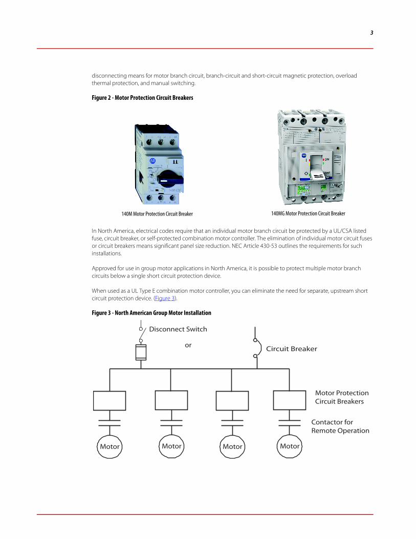
disconnecting means for motor branch circuit, branch-circuit and short-circuit magnetic protection, overload thermal protection, and manual switching.
Figure 2 - Motor Protection Circuit Breakers
In North America, electrical codes require that an individual motor branch circuit be protected by a UL/CSA listed fuse, circuit breaker, or self-protected combination motor controller. The elimination of individual motor circuit fuses or circuit breakers means significant panel size reduction. NEC Article 430-53 outlines the requirements for such installations.
Approved for use in group motor applications in North America, it is possible to protect multiple motor branch circuits below a single short circuit protection device.
When used as a UL Type E combination motor controller, you can eliminate the need for separate, upstream short circuit protection device. (Figure 3).
Figure 3 - North American Group Motor Installation
140M Motor Protection Circuit Breaker 140MG Motor Protection Circuit Breaker
Disconnect Switch
Motor Motor Motor Motor
or Circuit Breaker
Motor Protection Circuit Breakers
Contactor for Remote Operation

4
Motor Protection Circuit Breakers with Variable-Frequency Drives
The use of a motor protection circuit breaker or motor circuit protector (plus overload relay) for short circuit protection is required in cases where a bypass of the variable-frequency drive (VFD) is used (for example, a contactor).
In multiple motor applications NEC §430, part III, requires individual overload protection, that is, (thermal) overload function, on the load side of a VFD only.
Cat. No. 140M-D8V motor protection circuit breakers are suitable for application at output of VFDs in multi-motor installation. They can provide thermal overcurrent protection and also a disconnect means for the motor branch circuit and manual controller (ON/OFF). these motor protection circuit breakers are rated to provide short-circuit protection for individual motor circuit tap conductors, where required.
Figure 4 - Typical Multi-motor Installation with VFD
In international markets, to comply with the IEC 61439-1 requirements, the IEC motor protection circuit breakers are recognized and used as standalone short-circuit protection devices. Not until the available fault current exceeds the interrupting capability of the motor protection circuit breaker do back-up short-circuit protection devices need to be used (Figure 5).
Multi-motor installation
Motor Protection circuit Breaker (140M D8V)
Branch circuit protection device (140U-D, 140G Molded Case Circuit Breaker)
Controller (PowerFlex drives)

5
Figure 5 - Motor Installations Outside North America
Several key benefits of using motor protection circuit breakers include the following:
• Provide useful “group motor ratings” for North American applications
• Can be reset after fault occurs
• Visible trip indication
• Overload protection
• Provide local On-Off and isolation
Motor Overload Protection
Overload relays are used in a motor circuit to protect motors and motor conductors from damage caused by prolonged periods of overcurrent circuit conditions.
Overload relays perform the following functions:
• Allow harmless temporary overloads (such as motor starting) without disrupting the circuit
• Will trip and open a circuit if current is high enough to cause motor damage over a period of time
• Can be reset once the overload is removed
If motors are exposed to increased levels of continuous current and prolonged periods at locked rotor condition, damage to the motor and motor circuit conductors can occur. Motors can be damaged or destroyed under any of the following conditions:
• Low or high supply voltage
• Phase unbalance
• Continuous excessive loading
• Single-phasing
• Jam or stall conditions
• Ground/earth faults
• Mechanical failures such as seized motor bearing or binding mechanical linkages
Disconnect Switch
Motor Motor Motor Motor
Motor ProtectionCircuit Breakers
Contactor for Remote Operation

6
Figure 6 - Importance of Motor Protection
By selecting the proper type of overload relay with the appropriate functionality, the motor can be protected from most damage caused by these conditions.
Overload relays are rated by a trip class that defines the length of time it will take for the relay to trip in an overload condition. The most common trip classes are Class 10, Class 20, and Class 30. A Class 10 overload relay, for example, has to trip the motor offline in 10 seconds or less at 600% of the full load amps (which is usually sufficient time for the motor to reach full speed). Many industrial loads, particularly high inertia loads, require Class 30.
Figure 7 - Trip Class Comparison
Rotor Bar, 5%
Unknown, 10%
External, 16%
Stator Winding, 16%
Shaft Coupling, 2%
Bearing, 51%
Mechanical Causes of Motor Failures
75% of motor failures can be prevented by appropriate protection measures
Source … IEEE Petro-Chemical Paper PCIC-94-01.
0.1
1
10
100
1000
1 10
FLA Multiple
Tim
e (s
econ
ds)
Cold TripHot Trip
Class 30Class 20Class 15Class 10

7
Types of Overload Relays
Today two basic types of overload relays are available: thermal (eutectic alloy and bimetallic) and electronic. Let's take a closer look at each type of overload relay and their basic features.
Thermal Overload Relays
Eutectic Alloy Overload Relays
Eutectic alloy overload relays are typically used with NEMA motor starters. These overload relays use a solder type alloy within heater elements. As current moves through the heater element, the solder is heated until a predetermined melting point (trip point) is reached. At the trip point, the solder is instantaneously changed from a solid to a liquid, allowing the ratchet mechanism to open a normally closed contact, dropping out the starter coil circuit, Figure 8.
Figure 8 - NEMA Type Eutectic Alloy Overload Relay
Key features of a eutectic alloy overload relay include the following:
• Tamper-proof
• Not affected by nuisance tripping caused by vibration
• Manual reset only
• Single-phase "sensitive"
• Selectable trip classes 10, 20, 30
Bimetallic Overload Relays
Bimetallic overload relays use heater elements that indirectly heat bimetal strips. As the bimetal strips are heated, they flex towards a trip point, at which time a normally closed contact will open, dropping out the starter coil, Figure 9. In IEC bimetallic overload relays, the heater/bimetal are built in to the overload relay. To allow for added flexibility, the overload trip setting is adjustable over a range of motor full load current settings. The typical FLA
ToStarterCoil
PawlRatchet
T1L1
Heater
Eutectic Alloy
592 Eutectic Alloy Overload Relay

8
setting range would be 1.0:1.5 (min. to max. setting). IEC bimetallic overload relays are typically designed to Class 10 trip characteristics. This means that the overload relay will trip in less than 10 seconds at locked rotor current.
Figure 9 - IEC Type Bimetallic Overload Relay
Key features of an IEC type bimetallic overload relay are:
• Selectable manual/auto-manual reset
• Ambient temperature compensated
• Phase loss sensitivity
• Fixed Trip Class 10
Electronic Overload Relays
Electronic overload relays are the newest and fastest growing type of overload protection devices. Until recently, electronic overload relays were large, costly, and impractical for use on the vast majority of small motors used in industry today. With recent developments in electronic overload technology, the cost and size of the electronic devices have been significantly reduced while the functionality has been greatly increased. The latest electronic overload relay technology uses integral current transformers, application-specific integrated circuits (ASIC), and/or microprocessors along with electromechanical design principles to produce a compact, high functionality overload protection solution. Available in either NEMA or IEC versions, the principle of operation is the same. As motor current passes through the integral current transformers, power is available to supply the integrated circuit. By monitoring the three-phase power, the ASIC/microprocessor can process current data, and activate a trip mechanism on overload conditions, opening a normally closed contact and dropping out the motor starter coil circuit, Figure 10.
A basic electronic design provides thermal overload and phase loss protection. Trip classes may be fixed or adjustable at this basic level. Communication options may also be available.
L1L2L3
ToStarterCoil
Heater
BimetalStrip
Trip Bar
193-T Overload Relay

9
Figure 10 - Electronic Overload Relay
The E1 Plus™ electronic offers a wide 5:1 adjustment range in two models. The ED model provides fixed protection while the EE model provides selectable and expandable protection, and is available in single-phase and three-phase applications
E1 Plus ED Model features:
• IEC configuration
• 0.1…45 A current range
• fixed motor protection (Class 10)
• manual reset
E1 Plus EE Model features
• NEMA and IEC configurations
• 0.1…800 A current range
• selectable motor protection (Class 10, 15, 20 or 30)
• selectable manual/auto-manual reset
• single- and three-phase devices
• expandable with optional protection and communication modules
Communication Modules
The E1 Plus Communication Side-Mount Modules provide a cost-effective, seamless deployment of motor starters with your control architecture (See Figure 11).
Advantages
• includes integrated I/O
– provides convenient local termination of motor-related inputs (2) and outputs (1), simplifying the control architecture
Current Sensor
L1
L3
L2
MicroprocessorTo Starter Coil
E1 Plus Overload Relay

10
• provides operational and diagnostic data
– average motor current
– percentage of thermal capacity usage
– device status
– trip and warning identification
– trip history (5 previous trips)
• expands protective functions
– overload warning
– jam protection
– underload warning
Figure 11 - DeviceNet™, EtherNet/IP™ and PROFIBUS Communication Modules
Advanced Motor Protection
As a result of integrating a microprocessor or an application-specific integrated circuit (ASIC) as the brains of an electronic overload relay, the opportunity to add advanced protective functionality to the overload relay becomes very practical.
Figure 12 - Advanced Overload Protection Devices
DeviceNet Communication Module EtherNet/IP Communication Module PROFIBUS Communication Module
E300 Electronic Overload Relay

11
Besides basic overload protection, advanced electronic overload relay devices can offer additional functionality that previously would have required several additional protection devices to be used in the motor circuit. By consolidating many protective features into a single device, installation costs, component costs, panel size, and maintenance time can be significantly reduced while performance and efficiency of the system can be increased.
The E300™ electronic overload relay consists of three modules: sensing, control and communications. You have choices in each of the three with additional accessories to tailor the electronic overload for your application’s exact needs.
Protection Methods• Current Protection: This advanced electronic overload relay provides current protection through true RMS
current measurement of the individual phase currents of the connected motor. Based on this information, a thermal model that simulates the actual heating of the motor is calculated. Percent of thermal capacity utilization (%TCU) reports this calculated value and can be read via a communications network. An overload trip occurs when the value reaches 100%.
• Voltage Protection: With the option of voltage protection, users can protect against voltage issues: undervoltage, voltage imbalance, phase loss, frequency, and phase rotation.
• Power Protection: While the motor is powering a load, the optional sensing module with voltage, current, and ground fault current, will also protect the motor based on power. This option will monitor and protect for both excessive and low real power (kW), reactive power (kVAR), apparent power (kVA), and power factor for a specific application (for example, pump applications).
• Energy Monitoring: The optional sensing module will provide voltage, current, power (kW, kVAR, and kVA), energy (kWh, kVARh, kVAh, kW Demand, kVAR Demand, and kVA Demand), and power quality (power factor, frequency, and phase rotation) information down at the motor level. This information can be included in a company’s energy management system.
Communication Options
You can select from multiple communication options that integrate with Logix-based control systems:
• EtherNet/IP [Device Level Ring (DLR)]
• DeviceNet
Developers can easily add an advanced electronic overload relay to Logix-based control systems using Integrated Architecture tools like Add-on Profiles, Add-on Instructions, and Faceplates.
Integrated Architecture® systems incorporate a full range of control and information solutions that blend visualization, networking and system flexibility. The features included in Integrated Architecture solutions communicate via EtherNet/IP, which can be used to gather information from various devices, and the key feature is that any device that connects onto an EtherNet/IP network will integrate seamlessly with any other.
Integrated Architecture requires three components to control and monitor the electronic overload relays: Add-On Profiles, Add-On Instructions and Faceplates.
Add-On Profile (AOP)
The E1 Plus or E300 Add-On Profile provides an easy method for you to integrate the electronic overload relay into a Logix-based system. By selecting a device from the pull-down menu, you can configure the electronic overload relay, collect data and have a way to save the configuration data. You can use RSLogix 5000® /Studio 5000 software to do the configuration, which provides a common software package to not only program the controller, but to also configure the electronic overload relay. The overload appears as native I/O within the controller and also creates

12
readable tag names; rather than a generic name like “data”, it will provide a specific tag name such as “Output A” on an E1 Plus Overload Relay. Add-On Profile features include:
• simple commissioning
• meaningful tag names
• device configuration
• automatic device configuration
E1 Plus AOP• configuration tags such as
– overload warning
– jam protection
– underload warning
• (2) input and (1) output tags
• operational and diagnostics data such as
– percentage of FLA and TCU
– trip history (5 logs)
– trip and warning identification
– device status

13
E300 AOP• embedded and expansion I/O (digital and analog)
• control and sensing configuration
• overload protection
• advanced protection (available with the VIG sensing module only)
– current (imbalance)
– voltage (under/over voltage)
– power (reactive power consumption)
– control (test/maintenance)
Add-On Instruction (AOI)
The E1 Plus or E300 Add-On Instruction allows you to encapsulate the code and data commonly used in functions or device control, and protect intellectual property. The AOI along with the pre-configured faceplate permits program control from the faceplate or the Logix program, and allows you to view diagnostics from a remote HMI. After the Add-On Instruction is imported into a RSLogix 5000/Studio 5000 project, it can be added as a rung component into the ladder logic. After the Add-On Instruction is added to the ladder logic, you provide it with the electronic

14
overload relay and specify the inputs, outputs, and any required parameters. The Add-On Instruction is typically added to the Main Routine in the RSLogix 5000/Studio5000 project. These AOIs can be found in the “Sample Code” website.
E1 Plus AOI
For example, the first two rungs shown above enable Program Control of the E1 Plus Overload Relay. Command requests (Cmd) can be initiated from either the Logix Program (ProgOperReq) or FTViewME/SE E1 Plus Faceplate (OperOperReq).
E300 AOI
For example, the first two rungs shown above, enable Program Control of the E300 Overload Relay. Command requests (Cmd) can be initiated from either the Logix Program (ProgOperReq) or FTViewME/SE E300 Faceplate (OperOperReq).
Faceplate
The E1 Plus or E300 Faceplate is a pre-programmed graphic that is used in a FactoryTalk View project that allows you to easily use preconfigured status, control, and diagnostics displays. When used in combination with an Add-On Instruction, it becomes a very simple way to add graphics into an Operator Interface. These faceplates provide real

15
time data such as Full Load Amperage (FLA), Thermal Utilization, Trip Status and other valuable information from the electronic overload relay. You can also trend data over a period of time to help with diagnostics or integrate these faceplates into a PlantPAx solution. The faceplate is also an easy way to access data, view maintenance information, and control the process using pre-defined graphics that exist for the electronic overload relay.
E1 PlusHome display information examples• Trip Status• Average Current• % FLA
Trend display information examples• Average % FLA• % Thermal Utilized

16
E300Home display information examples• Trip and Warning Status• Average Current• I/O Status
Trend display information examples• Average % FLA• % Thermal Utilized
E300 with CIP Energy(1)
(1) This information will vary depending on the sensing module. This example is using the VIG sensing module.
Energy display information examples• Voltage• Current• Real, apparent and reactive power• Energy consumption

17
Distributed I/O
The E1 Plus communication module such as the EtherNet/IP network module provides convenient local termination of motor-related digital inputs (2) and outputs (1), simplifying the control architecture.
The E300 provides embedded I/O depending on the Control Module selected. Customers can expand out four digital I/O modules, plus four analog I/O modules along with a power supply and operator interface for control and diagnostics.
Figure 13 - E1 Plus EtherNet/IP Communication Module I/O

18
Figure 14 - E300 I/O
Example Application
Figure 15 shows the E1 Plus communication module “Output A” connected to the contactor coil. The contactor coil is energized until it sees an overload condition. The overload then de-energizes the coil, which opens the contactor and prevents the motor from running. This helps to protect the motor from any damage.

19
Figure 15 - 193-ETN Communication Module Output Controlling the Contactor Coil
EtherNet/IP Network
The E1 Plus and E300 Electronic Overload Relays connect to an Ethernet network and can be configured to communicate to an EtherNet/IP scanner such as an Allen-Bradley Logix controller. The overload relays have web capabilities that allow you to read information and configure parameters via a web browser. In addition, it also supports an SMTP server to send e-mail or text messages in the event of a warning or trip condition. The E1 Plus supports a Star Ethernet topology in which all Ethernet nodes wire back to a central Ethernet switch, hub, or router. The E300 has dual Ethernet ports that function as an Ethernet switch with RJ45 ports to connect Ethernet cable CAT5 type or better to. The E300 supports a Star, Linear, and Ring Ethernet topology in which all Ethernet nodes wire back to a central Ethernet switch, hub, or router.
Figure 16 - E1 Plus Web Page
BLU
BLU
OUT A
TBA TBA
M1
OL1
TBA
TBA
OL1
GND1
3
4
OL1
1 X2
1A
3 M1
FU3
T1
J1
(I2) (I1)
(A1) (A2)
(97) (98)
(13) (14)
(3) SSV
(2) IN2
(1) IN1
(GND)
A2 (-)
A1 (+)
(2) (1)
H1 H3 H2 H4
X1 X2
(95) (96)
E1 PLUSETHERNET/IP MODULE
15
14
18
G1
X1
J
3A

20
Figure 17 - E300 Web Page
CIP Energy
CIP Energy is a communications protocol that enables the exchange of energy information over the EtherNet/IP network. It makes energy data available over the network providing easy access to energy information, and allows greater visibility into energy usage at the operational level for easier baseline data creation. This helps optimize energy usage during production and diagnose potential problems with the specific machine or process.
By using the E300, you will have the ability to monitor valuable data such as voltage, current, energy, power, and other parameters. This will create awareness of energy consumption use at the equipment level allowing you to adjust energy usage of the machine and optimize tariff arrangements or demand-response programs with utilities.
How application works
In an example application where you are starting a machine with multiple motors simultaneously: You will have the ability to trend the E300 power parameters/load profiling. This allows you to identify and analyze power usage over a period of time or at startup. Furthermore, you can use demand management and/or load curtailment allowing you to understand “when” and “why” demand charges occur. By analyzing the data, you can make decisions to reduce electrical power cost, like scheduling motors to start up individually. This will reduce or limit the peak demand of the system.

21
Figure 18 - CIP Energy Monitoring Example
Diagnostic Information
Advanced electronic overload relays provide a wide variety of diagnostic information to monitor motor performance, proactively alert you to possible motor issues, or identify the reason for an unplanned shutdown. Information includes the following:
• Voltage, current, and energy
• Trip /warning histories
• % thermal capacity utilization
• Time to trip
• Time to reset
• Operational hours
• Number of starts
• Trip snapshot

22
Table 1 - Advanced Electronic vs. Traditional Overload Relays
Advanced Motor Protection Diagnostics (predicting motor life)
The E1 Plus optional side mount modules allow you to customize the device to your application’s specific needs. (Side mount modules are only available on the -EE model.)
• communication modules such as EtherNet/IP, DeviceNet and ProfiBus
• protection modules such as ground fault, jam, and protection
• reset modules such as remote reset and remote indicator
The E1 Plus communication module such as the EtherNet/IP network module allows direct access to motor performance and diagnostic data on an Ethernet-based network. Provides operational and diagnostic data such as % full load amperes (FLA), % thermal capacity utilization (TCU), trip/warning identification and five previous trips history log.
The E300 overload relay provides real-time motor diagnostic information to proactively indicate when a motor is having a problem allowing you to efficiently troubleshoot. It allows the user to monitor the following diagnostic information over a communications network:
• device status
• history of past five trips and five warnings
• trip status
• % thermal capacity utilization (%TCU)
• warning status
• hours of operation
• time to an overload trip
• number of starts
• time to reset after an overload
Thermal Electronic Advanced ElectronicProtection FeaturesOverload ✔ ✔ ✔Phase loss — ✔ ✔Ground fault — ✔ ✔Current imbalance ✔ — ✔Jam — ✔ ✔Over-/undervoltage — — ✔Voltage imbalance — — ✔Over-/under power — — ✔Diagnostics Features% Full load amperes — ✔ ✔% Thermal capacity utilization — ✔ ✔Voltage — — ✔Power — — ✔Energy — — ✔Integration FeaturesDeviceLogix — — ✔Logix controller — ✔ ✔

23
• trip history and snapshot
• current
• voltage
• ground fault current
• power
• voltage
• energy
The E300 supports one operator station that can be used as a user interface device. There are two stations that provide status and functions keys for motor control and allow you to upload and download E300 configuration parameters.:
• control station
• diagnostic station
Figure 19 - E300 Control Station Webpage

24
Figure 20 - E300 Diagnostic Station Webpage
For example, you can monitor the electronic overload %TCU (real-time heat) and %FLA (current draw) of the motor, providing you an indication as to when the overload might trip. When these values reach 100%, the electronic overload relay will force an overload trip. You can make critical decisions based on these values, like changing the process in order to prevent the overload from tripping. This information is useful when protecting an expensive system and reduce repair time when problems arise.
Life of a Typical Motor Installation
Over the life of a typical motor installation, several different fault conditions can occur, from high level faults such as short-circuits or ground faults to low level faults such as overloads and jam conditions. When selecting motor circuit protection devices, several questions should be raised:
• Is the motor circuit critical to the manufacturing process?
• What is the "total cost" of downtime in the application?
• Is the application more susceptible to certain types of fault conditions?
• Is Type 2 Coordination important?
• Do I need to collect motor data and be warned of impending fault?
• Are fuses or circuit breakers preferred for short-circuit protection?
Dependent on the answers to these questions (and possibly many others), the process can begin to specify the type of products required to adequately protect the motor circuit. For less critical applications such as a fan or blower, where critical manufacturing processes or safety issues are not a consideration, meeting code requirements with fuses and a traditional overload relay may be the ideal solution.

25
On the other hand, in a critical application, where the manufacturing process relies on a continuous flow of materials and downtime can be very costly, the best protection solution may require the following capabilities:
• selecting a short-circuit protection device that provides Type 2 Coordination
• selecting a electronic overload device that provides:
– ground fault protection
– jam/stall protection
– network communications to more closely monitor the motor data and application
Application Considerations
By properly outlining the application requirements and selecting the appropriate protection components, the optimum implementation costs and motor circuit protection scheme can be developed to optimize the maximum life and performance of the motor and application.
Downtime
From time to time, a motor protection device will cause an electric motor to stop working due to improper wiring, an electrical issue, a mechanical anomaly, or internal motor damage. When an unplanned event like this occurs, how does your facility handle this situation? Any time a critical motor expectantly stops your process, what is the cost of this lost production? How do you choose the right type of motor protection for your manufacturing facility?
The answer to this question most likely depends on your lost production revenue (cost of unplanned electric motor down time). If lost production revenue is minimal, you might want to consider using a basic bimetallic or eutectic alloy-based motor protection. These types of motor protection products meet the minimal government requirements, and they prevent internal thermal damage to the electric motor. The main drawback is that they do not provide any advanced warning that an event is about to occur, and they do not provide any information about why the event occurred.
If lost production revenue is substantial, you may want to consider using electronic-based motor protection. These types of motor protection products meet government requirements of thermal protection, but they also provide other types of electrical-based protection such as phase loss, asymmetry, improper voltage, rotation mismatch, ground fault (earth leakage) current, and more. Advanced electronic motor protection devices provide communications capabilities to alert for possible motor problems, project when the motor is going to stop, and indicate the reason why the motor stopped unintentionally.
For example, in a pumping application, electronic motor protection devices can simulate the internal temperature of an electrical motor providing mechanical power to a pump. They can send an alarm by text message or email if the heat rises beyond a specified level. They can also be integrated into an existing SCADA infrastructure using communication networks such as EtherNet/IP to provide advanced warnings and help you avoid costly downtime.
Electronic motor protection devices cost more than a basic bimetallic or eutectic based motor protection device, but it can be significantly less compared to the cost of your unplanned electric motor down time.
Motor Life
It’s a common occurrence to push a product a little too hard. When a motor is overloaded and we are aware of it, we generally know that we need to shut it down and wait for it to cool, or a safety switch will do the job for us, preventing overheating.

26
When this happens too often, however, the motor life is permanently shortened, causing the potential for unforeseen downtime while the overheated motor shuts down, cools off and gets ready to start again.
Older (electromechanical) motor protection technology will protect a motor from overheating by shutting the motor down – but that’s reactive (after the problem) rather than proactive. Production stops while the motor recovers – potentially risking hundreds of thousands of dollars in revenue.
Instead of an electromechanical solution, there are electronic-based options that can monitor the motor electrically and mechanically – these options can help you predict how and when a motor might fail so you can pre-empt the problem. If the motor does fail, the diagnostics will help you resolve the problem as quickly as possible.
The secret of electronic overload relays for electrical motor protection is in how information about what’s happening inside the motor is communicated to the outside world. It can help to more accurately predict when a motor might fail so you can make a decision about how to proceed.
In many cases, every second counts. In a cement mixing application with 30 seconds left in the process and an impending motor trip in 45 seconds, timely information will let you finish mixing the batch without risking the product or the motor. Better data leads to better decisions.
This is only one example of the data available. If you’re on an energy management agreement and several times a year your utility wants you to cut usage, with data provided by the electronic overload relay, you can quickly assess how much power (kW) each motor is using and shut down non-critical loads.
Rather than relying on maintenance personnel to notice a shutdown and call it in, electronic-based motor protection can send a signal to the control station and a message to maintenance before the shutdown. If the motor does trip, all the data about the event is captured for examination to help prevent a repeat in the future. Electronic overload relays also present a significant cost saving opportunity. If there is something critical in your application, than you may wish to consider an electronic overload instead of a thermal option.
Figure 21 helps you to compare your electric motor application to better decide which overload is the right solution for your application. How do you begin the selection process? The answer to this question depends on the specific electric motor application and its impact to lost production revenue due to unplanned electric motor down time.

27
Figure 21 - Application Examples
Figure 22 - Life of a 40 Hp Motor
Standalone
Stamping Press (Hydraulic Pump)Application Example
Shock and vibration environment.Requires manual reset only. Selectable tripclass options. Load with constant draw andlow probability of tripping. No machinefunction, operator task or environmentalvariance that will cause trips often. Tripscaused by abnormal events.
Conveyor Belt for GravelApplication Example
Loads with varying draw and higherprobability of tripping. Changes in loadcaused by machine function (torn belt),operator task or environmental variancethat can cause more frequent trips. Tripscaused by normal operation. Networking,I/O integration and diagnostics.
Electronic
Electronic
Most Likely
Pharmaceutical HVAC (Chiller Pump)Application Example
Energy consumption. Power monitoring.Loads with varying draw and higherprobability of tripping. Changes in loadcaused by machine function, operator taskor environmental variance that can causemore frequent trips. Trips caused bynormal operation. Networking,expandable I/O and real-time diagnostics.
Ventilation FanApplication Example
Manual and automatic reset modesrequired. DC applications. Adjustablerange dial. Load with constant draw andlow probability of tripping. Currentimbalance. No machine function, operatortask or environmental variance that willcause trips often. Trips caused byabnormal events.
Which motoroverload should Iselect for myapplication?
Electronic
AdvancedElectronic
Standalone
BimetallicEutectic Alloy
What’s myapplication?
Most Likely Most Likely
Cost of Down Time$ $$$
Which motoroverload should Iselect for myapplication?
Which motoroverload should Iselect for myapplication?
Which motoroverload should Iselect for myapplication?
Crusher Application40 Hp Motor (50 A FLC)
100%
WARNING!
15 sec0.5 sec2 sec 40 secTime
Motor FLC 50
0
100
500
1,000
5,000
10,000
50,000
100,000
Ie
Solid-stateOverloadProtectionDevices
TraditionalOverloadProtectionDevices

28
Table 2 - Protection Types Available from Overload Protection Devices
Terminology
To help understand Coordinated Motor Circuit Protection, you must be familiar with the characteristics and definitions related to fuses, circuit breakers, overload relays, short-circuit, and overload protection.
Ampere Rating- The continuous current carrying capability of a fuse or circuit breaker.
Ampere-squared Seconds (I2t) - An expression related to the thermal energy associated with current flow.
Available Fault Current - The maximum possible short-circuit current that can flow in an unprotected circuit.
Circuit Breaker - A device designed to open and close a circuit by non-automatic means and to open the circuit automatically on a predetermined overload current.
Clearing Time - The total time measured from the beginning of the fault to the interruption of the circuit.
Current-Limiting Circuit Breaker - A circuit breaker that does not employ a fusible clement and that when
operating within its current limiting range, limits the let-through I2t to a value less than the I2t of a 1/2 cycle wave of the symmetrical prospective current.
Current Limiting Fuse - A fuse which will limit both the magnitude and duration of current now under short-circuit conditions. The available fault currents a fuse will clear in less than 1/2 cycle, thus limiting the actual magnitude of current flow.
Fuse - An overcurrent protective device with a fusible link that operates to open the circuit on an overcurrent condition.
High Level Fault - Short-circuit currents between the threshold current of a fuse that would be used for the branch circuit protection of a motor in a given application and the test current for the controller of that motor, per the short-circuit test of UL 508.
Interrupting Rating - The maximum short-circuit current that an overcurrent protective device can safely open or clear.
Let-through Energy (I2t) - A measure of thermal energy developed within a circuit during the total clearing time of the fault current.
Low-level Fault - Short-circuit currents that are less than the threshold current of a fuse that would be used for the branch circuit protection of a motor in a given application.
Fault TypeShort-Circuit Ground/Earth Overload Phase Loss Jam/Stall Impending Trip
Protection Device Type
Fuses or Circuit Breakers
Traditional Overload Protection Devices Responds with Overload Trip Curve
Trip due to low-level
ground faultElectronic Overload Protection Devices
Advanced Protection via Network Communications
– % Thermal Capacity used– Phase unbalance– Start-Stop reset control– Restart limit
High-level faults Low-level faults

29
Overcurrent - A condition existing in an electrical circuit when normal current is exceeded. Overcurrents occur in two distinctly separate forms -overloads and short circuits.
Overload - An overcurrent that exceeds the normal full-load current of a circuit.
Peak Let-through Current (Ip)- The maximum instantaneous peak current passed through a short-circuit protective device when clearing a fault current of specified magnitude.
RMS Current - The effective, root-mean square value of current, and the measure of its heating effect. The RMS value is calculated as the square root of the mean of the squares of all the instantaneous values of the current throughout one cycle. RMS alternating current is the value of an alternating current that produces the same heating effect as a given value of direct current.
Short-circuit Current - Excessive current caused by insulation breakdown or wiring error. Short-circuit currents leave the normal current carrying path of the circuit, such as line-to-line or line-to-ground. Short circuits are typically detected and cleared by the branch circuit protective devices.
Single-phasing - The condition that exists when one phase of a three-phase power system opens. Single-phasing results in unbalanced currents and overheating in polyphase motors and other three-phase inductive devices. Proper selection of dual-element time-delay fuses and/or protective relays will help protect motors from damage during single-phasing conditions.
Threshold Current - The magnitude of current a which a short-circuit protection device becomes current limiting.
UL Class of Fuse/CSA Fuse Designations - Underwriters Laboratories and the Canadian Standard Association have developed basic physical specifications (size, rejection features, labeling) and electrical performance requirements
(interrupting rating, maximum Ip and I2t) for fuses with voltage ratings of 600 volts or less. If a fuse meets these requirements, it can be designated by a UL class of fuse or a CSA fuse designation. Typical UL fuse classes are K l , K5, RK I, RK5, J, T, and CC. Typical CSA fuse designations are HRCI-T HRCI-R, HRCI-J, and HRCII-C.
Voltage Rating - The maximum value of system voltage in which a fuse can be used and safely interrupt an overcurrent. Exceeding the fuse voltage rating impairs its ability to clear an overload or short-circuit safely.

Publication 193-WP008Supersedes Publication 193-WP008A
Allen-Bradley, Rockwell Softwa
Trademarks not belonging to R
Rockwell Automation maintainhttp://www.rockwellautomatio
B-EN-P - February 2016-EN-P March 2015 Copyright © 2016 Rockwell Automation, Inc. All rights reserved. Printed in the U.S.A.
re, Rockwell Automation, and LISTEN. THINK. SOLVE are trademarks of Rockwell Automation, Inc.
ockwell Automation are property of their respective companies.
s current product environmental information on its website atn.com/rockwellautomation/about-us/sustainability-ethics/product-environmental-compliance.page.