low temperature sintering additives for silicon nitride · manga, nana; korean friends: 1st lee,...
TRANSCRIPT

Max-Planck-Institut für Metallforschung Stuttgart
Dissertation an der Universität Stuttgart Bericht Nr. 137 August 2003
Low Temperature Sintering Additives for Silicon Nitride
Branko Matovic

Low Temperature Sintering Additives for Silicon Nitride
Dissertation
Von der Fakultät Chemie der Universität Stuttgart
zur Erlangung der Würde eines
Doktors der Naturwissenschaften (Dr. rer. nat.)
genehmigte Abhandlung
Vorgelegt von
Branko Matović
Aus Kraljevo, Serbien
Hauptberichter : Prof. Dr. rer. nat. Fritz Aldinger
Mitbericher : Prof. Dr. rer. nat. Dr. hc. mult. Günter Petzow
Tag der mündlichen Prüfung : 15.08. 2003.
Institut für Nichtmetallische Anorganische Materialien der Universität Stuttgart
Max-Planck-Institut für Metallforschung, Stuttgart
Pulvermetallurgisches Laboratorium
2003


Dedicated to my daughter Doroteja


Acknowledgements This Ph. D. work was done from May 2000 to April 2003 in Max-Planck Institute for Metal
Research, Stuttgart, supported by a Max-Planck-Society Scholarship.
I am glad to take this opportunity to thank my thesis advisor Prof. Dr. Fritz Aldinger for his
earnest involvement and competent guidance in this work.
My special thanks to my group leader Dr. G. Rixecker, with whom even serious work is an
entertainment.
I am taking this opportunity to thank Prof. G. Petzow who friendly helped me and accepted to
become the "Mitberichter" for my final examination. I also want to thank Prof. E. J.
Mittemeijer for giving consent to examine my thesis.
There were many people who helped me: Mr. Kosanovic, Mr. Mager, Mr. Schweitzer, Mr.
Kummer, Mr. Labitzke, Miss Predel, Dr. Bunjes, Mr. Bruckner, Mr. Hammoud, Mrs.
Feldhofer, Mrs.Schäufeler...and many others. Sincere thanks to all of them.
There were many people who made my working and living easier and full of fun. I would like
to thank Krenar, friends from the "Indian community: Suba, Biswas, Gautam, Ravi, Datta,
Manga, Nana; Korean friends: 1st Lee, 2nd Lee, 3rd Lee... Ann, many Parks; Sandra, Stefanie,
Dirk, Anita, Ute, Aleksandar, Marija, Zaklina, Dragan, Amin, El-Shazlyt, Jia and many
others.
My special thanks to Dr. S. Boskovic who is "guilty" why for my spending three nice years in
PML.
Finally, I am indebted to my family (Dragica and Doroteja) who have borne my pressure with
patience and good humour especially to my daughter Doroteja.


1
ABSTRACT
This work deals with sintering additives for the low temperature pressureless sintering of
Si3N4, via a transient liquid technique. Much attention has been given to the development of a
sintering process using low-cost Si3N4 powder (Silzot HQ, Germany) as the starting material
and employing sintering additives which are also both economically attractive and enable
sintering at low temperatures. Two new additives based on the Li2O-Y2O3 system (LiYO2),
and on the Li2O-Al2O3-SiO2 system (LiAlSiO4) were investigated in this study. The grain
boundary liquid phases that form from the two additive systems possess similar eutectic
temperatures (<1300°C) enabling liquid phase sintering of Si3N4 at temperatures as low as
1500°C.
Different procedures for powder homogenization were investigated first. This was necessary
because the grain size and shape distribution of the Si3N4 powder under investigation differ
significantly from those of powders normally used for the liquid phase sintering of Si3N4.
Among three mechanical mixing processes for the introduction of additives in Si3N4 powder,
namely attrition milling, ball milling and vibratory milling, best results were obtained with
attrition milling. This method yielded a uniform dispersion of the additive powder in a fine
unagglomerated Si3N4 matrix without contamination. It also produced good sintering
characteristics.
The densities obtained for sintered samples with 15 and 20 wt% of LiYO2 and with 10 wt% of
LiAlSiO4 additives, respectively, were more than 98% of the theoretical density. Li2O is
removed in gaseous form during sintering and thus, the liquid phase is partially transient. This
creates some potential for good high temperature properties in spite of the low sintering
temperature.
The densification step is followed by a phase transformation from α−Si3N4 to β−Si3N4 in both
cases. The lag between these two stages in the sintering process is more pronounced in the
Li2O-Al2O3-SiO2 additive system due to the high viscosity of the transient liquid. The degree
of α→β phase transformation increases during prolonged sintering. The reaction kinetics of
the phase transformation were found to be of first-order in both systems.
The microstructure of Si3N4 materials with the both additives sintered at 1600°C for 8 h is
characterized by a homogeneous distribution of elongated β−Si3N4 grains and glassy phase,
located in thin layers at grain boundaries and triple points. The β−Si3N4 grains are surrounded
by a glassy phase at almost all grain contacts indicating a good wetting behavior.

2
Grain growth was observed to be anisotropic in both cases, leading to rod-like crystals
providing a microstructure which has potential for enhanced fracture toughness. Fracture
toughness values of 6.7 MPa⋅m1/2 and 6.2 MPa⋅m1/2 were measured for the specimens sintered
with 15 wt% LiYO2 and 10 wt% LiAlSiO4 additives, respectively.
The thermal conductivity of Si3N4 with the LiYO2 additive is higher in comparison to the
material sintered with LiAlSiO4 additive. The decrease in the thermal conductivity in the
latter is attributed to the dissolving of aluminum and oxygen in the β-Si3N4 grains which act
as phone scattering sites.

3
Contents Abstract 1
Contents 3
List of figures 6
List of tables 10
1 Introduction.........................................................................................................................12
2 Literature review.................................................................................................................14
2.1 Crystal structure of silicon nitride...........................................................................14
2.2 Preparative routes for silicon nitride powders....................................................... 19
2.3 Processing techniques of silicon nitride ceramics.................................................. 22
2.4 Sintering................................................................................................................ 24
2.4.1 Basic theory of liquid phase sintering..................................................... 24
2.4.1.1 Factors controlling liquid phase sintering.................................24
2.4.2 Basic mechanisms of liquid-phase sintering........................................... 27
2.4.2.1 Particle rearrangement............................................................. 27
2.4.2.2 Solution-reprecipitation........................................................... 28
2.4.2.3 Solid-state or skeleton sintering............................................... 29
2.5 Liquid phase sintering of silicon nitride................................................................ 30
2.5.1 Densification........................................................................................... 30
2.5.2 Phase transformation................................................................................31
2.5.3 Grain growth........................................................................................... 31
2.6 Microstructure........................................................................................................ 32
2.7 Sintering additives...................................................................................................33
2.8 Mechanical Properties of Si3N4...............................................................................36
2.9 Thermal properties..................................................................................................39
2.10 Oxidation resistance of Si3N4................................................................................40
2.11 Applications..........................................................................................................41
2.12 Motivation.............................................................................................................42
3 Experimental procedure.....................................................................................................43
3.1 Characterization................................................................................. ....................44

4
3.1.1 Measurements of specific surface area and particle size distribution......44
3.1.2 X-ray diffraction......................................................................................44
3.1.3 Chemical analysis....................................................................................44
3.1.4 Scanning electron microscopy.................................................................45
3.2 Results.................................................................................................................... 45
3.2.1 Starting material..................................................................................... .45
3.3 Additive preparation............................................................................................. 47
3.4 Greenbody fabrication........................................................................................... 49
3.4.1 High temperature thermogravimetry...................................................... 50
3.4.2 Dilatometry............................................................................................ .50
3.4.3 Sintering................................................................................................. .51
3.5 Characterization of the ceramics........................................................................... 52
3.5.1 Sintered density and mass loss............................................................... 52
3.5.2 Room temperature fracture toughness.................................................... 52
3.5.3 Determination of thermal conductivity................................................... 53
4 Powder processing...............................................................................................................55
5 Densification........................................................................................................................62
5.1 Dilatometric study.................................................................................................. 62
5.1.1 Densification temperature........................................................................62
5.1.1.1 Si3N4-LiYO2-SiO2 system..................... .................................. 62
5.1.1.2 Si3N4-Li2O-Al2O3-SiO2 system.................................................67
5.2 Sintering density............................................................................ ........................73
5.3 General remarks......................................................................................................80
6 Phase transformation..........................................................................................................81
6.1 Temperature and time dependence.........................................................................81
6.2 Influence of additive content...................................................................................83
6.3 Kinetics of phase transformation............................................................................84
6.4 Transformation mechanism.....................................................................................86
6.5 Relation of transformation to densification............................................................87

5
7 Microstructure ...................................................................................................................90
7.1 Microstructural observation in systems sintered with LiYO2 additive ...................91
7.2 Microstructural observation in systems sintered with LiAlSiO4 additive...............96
8 Properties ..........................................................................................................................100
8.1 Fracture toughness and hardness...........................................................................100
8.2 Thermal conductivity............................................................................................102
9 Conclusions ........................................................................................................................106
Zusammenfassung................................................................................................................ 108
References..............................................................................................................................118
Cuuriculum Vitea (Lebenslauf)...........................................................................................125

6
List of figures
Figure Contents Page
2.1. a Crystal structure of trigonal α-Si3N4 15
2.1. b Crystal structure of hexagonal β-Si3N4 16
2.1c Crystal structure of γ-Si3N4. 17
2.2 Phase relationship in the M-Si-Al-N-O System 18
2.3 Wetting behavior between a liquid and a solid 25
2.4 Equilibrium contact angle between a liquid and a solid 26
2.5 Equilibrium dihedral angle between a grain and the liquid phase 26
2.6 Schematic diagram illustrating the three stages of liquid-phase sintering on a typical sintering curve 29
2.7 Phase transformation in Si3N4-SiAlON-additive system 31
2.8 Typical microstructure of a liquid-phase sintered Si3N4 ceramics 32
2.9 Dependence of the strength of pressureless sintered Si3N4 on the density 37
3.1 Flow chart of the experimental procedure 43
3.2 Typical Scanning electron micrographs of as-received silicon nitride powder 46
3.3 XRD pattern of as-received Silzot HQ Si3N4 powder 47
3.4. (a) XRD pattern of synthesized LiYO2 additive 48
3.4. (b) SEM micrograph of synthesized LiYO2 additive 48
3.5 XRD pattern of Li-exchanged zeolite at 800 and 1000°C 49
3.6 Schematic diagram of sample preparation method 50
3.7 Schematic diagram of sintering schedule 51
3.8 A schematic view of the Vickers’ microhardness test 53
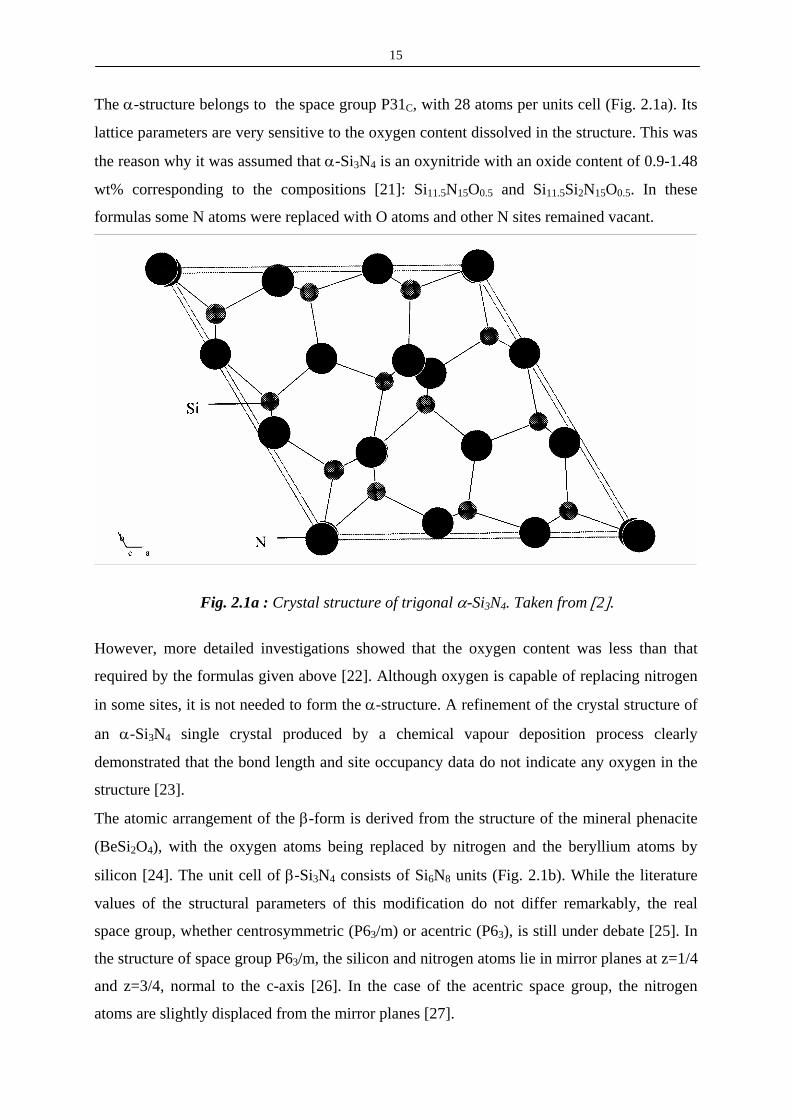
3.9 Experimental set up for measurement thermal diffusivity
3.10 Typical curve for thermal diffusivity of Si3N4 ceramics 54
at ambient temperature
4.1 The effects of milling time on the specific surface area 56
4.2 SEM photomicrographs of as-received Si3N4 and a powder attrition milled for 4 h 57
4.3 Oxygen content during processing with LiYO2 additives

7
(milled for 1,2,4 h ; d-dry milling; w-wet milling) 58
4.4. (a) Backscattered electron images of green compacts showing the Y distribution (LiYO2 containing Si3N4 mixtures prepared by ball and attrition milling for 1h) 59
4.4. (b) Backscattered electron images of green compacts showing the Y distribution (LiYO2 containing Si3N4 mixtures prepared by ball and attrition milling for 2 and 4 h). The light spots represent the additive that is distributed in the green compacts 59
4.5 SEM micrographs of polished and plasma etched sections of the sintered samples made by different homogenization procedures (a-attrition milling and b-vibratory milling) 60
5.1 Length change of Si3N4 green bodies (A-5 wt%, B-10 wt%, C-15 wt%, D-20 wt% of LiYO2) between room temperature and 1500°C 63
5.2 Linear shrinkage versus additive content in dilatometer experiments, after a holding time of 5 min at 1500°C 63
5.3 Density according to dilatometric measurements of Si3N4 with 15 wt% of LiYO2 additive after a holding time of 5 min at the temperatures indicated 64
5.4 Influence of the amount of LiYO2 on the densification of Si3N4 samples fired at 1500°C with a holding a time of 5 min 65
5.5 Shrinkage (a) and shrinkage velocity (b) of a silicon nitride green Body with 15% LiYO2 additive showing characteristic features at (1) 1180°C; (2) 1275°C; (3) 1364°C and (4) 1453°C 66
5.6 Length change of Si3N4 green bodies (A-5 wt%, B-10 wt%, C-15 wt%, D-20 wt% of LAS between room temperature and 1500°C 68
5.7 Linear shrinkage versus LAS additive content in dilatometer experiments, after a holding time of 5 min at 1500°C 68
5.8 Density according to dilatometric measurements of Si3N4 with 10 wt% of LAS additive after a holding time of 5 min 69
5.9 Influence of the amount of LAS additive on the densification of Si3N4 samples fired at 1500°C with a holding a time of 5 min 70
5.10 Shrinkage (a) and shrinkage velocity (b) of a silicon nitride green Body with 15% LAS additive showing characteristic features at (1) 1080°C, (2) 1180°C; (3) 1275°C and (4) 1490°C 71
5.11 The difference in the densification behavior between Si3N4-LiYO2 and Si3N4-LiAlSiO4 ceramics with 15% of additive sintered at different temperatures from 1500°C up to 1700°C with a holding time of 5 min 73
5.12 Relative densities at 1500°C vs. annealing time for Si3N4 with LiYO2 additives (5, 10, 15 and 20%) 74
5.13 Relative densities at 1500°C vs. anealing time for Si3N4 with

8
LiAlSiO4 additives (5, 10, 15 and 20%) 75
5. 14 Lithia losses of Si3N4 compacts with 15 wt% of LiYO2 additive during dilatometric measurement and upon prolonged annealing time at 1500°C 76
5.14 Mass loss as a function of temperature for Si3N4 compacts with different amounts of LiYO2 and LiAlSiO4 additives during sintering with a holding time of 5 min 77
5.15 Mass loss of Si3N4 ceramics with the additive systems LiYO2 (LY) and LiAlSiO4 (LAS), heat-treated at 1550°C (a) and 1600°C (b) under 0.1 MPa N2 as a function of soaking time. 78
5.16 Mass loss of Si3N4 ceramics with the additive systems LiYO2 (LY) And LiAlSiO4 (LAS), heat-treated at 1550°C (a) and 1600°C (b) Under 0.1 Mpa N2 as a function of soaking time. 78
5.17 Mass loss of lithium in Si3N4 samples sintered at various temperatures 79
6.1 The phase transformation as a function of temperature in the Si3N4-LiYO2 and Si3N4-LiAlSiO4 systems for 5 minutes of annealing 81
6.2 The phase transformation as a function of temperature in the Si3N4-LiYO2 and the Si3N4-LiAlSiO4 systems (15 wt%) for 1 hour of annealing 82
6.3 The effect of additive content on phase transformation during sintering of Si3N4-LiAlSiO4 ceramics at different temperature 83
6.4 The effect of additive content on phase transformation during sintering of Si3N4-LiAlSiO4 ceramics at 1500°C 84
6.5 Linear dependence of the logarithm of the α-Si3N4 concentration on time for Si3N4 containing various amounts of the LiYO2 additive at 1450°C 85
6.6 Linear dependence of log α-phase on time for Si3N4 containing various amount of the LiALSiO4 additive at 1500°C 86
6.7 Densification and phase transformation as a function of sintering temperature for LiYO2-Si3N4 and LiAlSiO4-Si3N4 systems 87
6.8 The relationships between densification and phase transformation as a function of sintering time for LiYO2-Si3N4 and LiAlSiO4-Si3N4
systems for 15 wt% of additive at 1500°C 88
7.1 SEM micrograph of polished and plasma etched section of samples with 15 wt% additive sintered at 1500°C for 0.5 h (a) and for 2 h (b) and for 8 h (c) 91
7.2 SEM image of polished and CF4 plasma-etched cross section of the sintered Si3N4 material doped with LiYO2 additive 92
7.3 SEM microstructure of Si3N4 ceramics with total additive content of LiYO2 by (a) 10 wt%, (b) 15 wt%, (c) 20 wt%, respectively 93

9
7.4 SEM micrograph of polished and plasma etched section of samples with 15 wt% additive sintered at 1600°C for 8 h 94
7.5 XRD pattern of a sample with 15 wt% of additive sintered at 1600°C for 8 h 95
7.6 Backscattered electron images and EDX of β-Si3N4 grain 96
7.7 Backscattered electron images and EDX of intergranuly phase 96
7.8 SEM micrograph of polished and plasma etched section of samples with 15 wt% of LiAlSiO4 additive sintered at 1500°C for 8 h 98
7.9 SEM micrograph of a polished and plasma etched section of a sample sintered with 10 wt% of additive at 1600 °C for 8 h 98
7.10 SEM micrograph of a polished and plasma etched section of a sample sintered with 15 wt% of additive at 1600 °C for 8 h 99
7.11 Backscattered electron images and EDX of β-Si3N4 grain. Sample is sintered at 1650°C for 1 h 99
8.1 Variation of fracture toughness and hardness as a function of the annealing time in Si3N4 ceramics sintered with LiYO2 and LiAlSiO4 additive systems, respectively at 1500°C 100
8.2 Microstructure and crack path in Si3N4 ceramic sintered with 15 wt% of LiAlSiO4 additive at 1500°C for 8 h 101
8.3 Microstructure and crack path in Si3N4 ceramic sintered with 15 wt% of LiYO2 additive at 1600°C for 8 h 102
8.4 Temperature dependence of thermal diffusivity of Si3N4 ceramics sintered with 15 wt% of LiYO2 (a) and SiAlSiO4 (b) additive 104

10
List of Tables
Table Contents Page
2-I Crystal structure and lattice parameters of Si3N4 modifications 14
2-II Production of Si3N4 powders 19
2-III Typical properties of Si3N4 powders produced by various processing techniques 20
2-IV Microstructural features of liquid-phase sintering as a function of dihedral angles (ψ) 27 2-V Oxide additives used for the densification of Si3N4 34
2-VI Summary of sintering studies of Si3N4 at atmospheric pressure with magnesia and yttria additives and their compounds 35
2-VII Typical properties (at room temperature) for advanced hot-pressed and pressureless sintered silicon nitrides 36
2-VIII Flexural strength data on pressureless sintered Si3N4 38
2-IX Time evolution of Si3N4 from chemical compound to an advanced ceramic 41
3-I Characteristic analysis of as-received Silzot HQ Si3N4 powder 46
IV-I Effects of milling time and different types of homogenization procedures on the properties of Si3N4 mixtures 56
IV-II Densities after sintering at 1600°C with 5% of LiYO2 additive (TD-theoretical density) 58
5-I Phase contents of the samples quenched at different temperatures 67
5-II Phase contents of the samples quenched from different temperatures 72
5-III Densities after sintering with different amounts of the LiYO2 additive 75

11
5-IV Densities after sintering with different amounts of the LiAlSiO4 additive 77
8-I The effect of the additive amount on thermal conductivity for Si3N4 ceramics sintered with LiYO2 additive 103

12
1 INTRODUCTION
Silicon nitride (Si3N4) has been studied extensively during the last 50 years. Si3N4 based
ceramics were found to possess promising thermal and mechanical properties at high
temperatures since 1955 [1]. As reaction bonding was the only method to fabricate Si3N4
ceramics at that time, the products were not completely dense. For an optimum utilization of
the inherent good properties of Si3N4, the powders must be fully densified to compacts [2].
High density materials were first obtained early in the 1960s by hot-pressing with small
amounts of various oxide and nitride additives [3]. However, only simple shapes could be
fabricated by this process. In the beginning of the 1970s research focused on the applications
of Si3N4 as a structural material for gas turbines [4]. As a result pressureless [5] and gas
pressure sintering [6] techniques were developed. This made possible the fabrication of
components having high density and complex shape. During the past 30 years, many different
aspects have been explored, such as the fundamental properties of Si3N4, powder production,
porous and dense Si3N4 and amorphous thin films for applications in electronics. It was found
that Si3N4 possesses a unique combination of properties, such as high strength at ambient and
high temperatures, good thermal shock resistance due to a low coefficient of thermal
expansion, relatively good resistance to oxidation compared to other high-temperature
structural materials, high wear resistance and high thermal conductivity. In addition, the
density of Si3N4 is only about 40% of superalloys. This combination of properties makes it
possible for Si3N4 to replace metallic components that are conventionally used as structural
materials.
During investigations on the sintering of Si3N4, it was also found that some oxides can be
dissolved into Si3N4 grains [7, 8]. Thus, the resulting material is not pure silicon nitride
anymore. “Silicon nitride ceramics” is thus a general name for multicomponent mixtures or
alloys of Si3N4. The solid solutions with Al2O3 have been referred to as Sialons. The creep
and corrosion resistance of high density Sialon was envisaged to be higher than that of
sintered Si3N4 ceramics because of the reduction or elimination of the grain boundary phase
[9] which could be aspired to with these materials.
Si-N bonds are predominantly covalent and this is the source of the excellent intrinsic
properties of silicon nitride ceramics. However, due to the high degree of covalent bonding, it
is very difficult to sinter these materials to full density. As a consequence, several alternative
techniques have been developed to improve the densification of Si3N4 based ceramics [10].

13
Fully dense Si3N4 can be produced by the addition of densification additives which allow
liquid phase sintering (LPS). A wide range of sintering additives for Si3N4 have been explored
to date [11, 2]. Since the densification rate is strongly related to the type and amount of
sintering additives, as are the microstructural development and the thermal and mechanical
properties of sintered bodies, there is considerable effort to find and optimize sintering aids
for high performance Si3N4 materials.
In spite of their excellent properties and great potential, the application of Si3N4 based
ceramics is still limited. The main reasons for this is the high cost of raw materials, i.e. Si3N4
and the sintering additives, in addition to the production process being cost-intensive [12]. In
general, high-quality Si3N4 grades are used in combination with rare-earth oxides (RE2O3 with
e.g., RE=Y, Ce, Yb, Lu) [2], which are not only expensive but require high sintering
temperatures. Therefore, there is a ongoing search for a production process that utilizes low-
cost Si3N4 powder and sintering additives which are equally cheap and enable attainment of
lower sintering temperatures. Recently, more attention has been given to low-temperature
sintering of Si3N4 ceramics with the aim of reducing manufacturing costs [13, 14].
The present investigation deals with the use of low-temperature sintering additives for
pressureless sintering of Si3N4, via a transient liquid phase technique. Two new additives in
the Li2O-Y2O3 and Li2O-Al2O3-SiO2 systems have been employed. The grain boundary liquid
phases (GBLP) originating from these two additives possess a similar eutectic temperature (<
1300°C) but differ in viscosity [15]. It turns out that the chemistry and therefore viscosity and
crystallization behavior of the intergranular phase can be tailored by evaporating partially the
Li2O. At the same time, there is a substantial reduction in the processing temperature. From a
scientific perspective, this is a good case for studying the role of GBLP in these sintered
materials.
The major objectives of this research can be summarized as follows:
1. Optimizing the results of pressureless-sintering in the Si3N4-Li2O-Y2O3 and Si3N4- Li2O-
Al2O3-SiO2 systems. This includes finding the best powder homogenization procedures,
the lowest effective sintering temperature and the optimum amount of additive.
2. Determining the reaction kinetics of densification, phase transformation and grain growth.
3. Characterizing the evolution of the microstruture. 4. Characterizing thermomechanical and mechanical properties of the sintered materials.

14
2 LITERATURE REVIEW
2.1 Crystal structure of silicon nitride
Silicon nitride exists in three crystallographic modifications designated as the α, β and γ
phases. While the α and β modifications can be produced under normal nitrogen pressure and
have great importance in the production of advanced ceramics, the recently discovered γ-
Si3N4 can be formed only at extremely high pressures [16] and has no practical use yet.
In a simple chemical picture, chemical bonding in α- and β-Si3N4 are due to the overlap of
the sp3 hybrid orbitals of silicon atoms with the sp2 hybrid orbitals of the nitrogen atoms.
Each nitrogen atom has a remaining p atomic orbital which is nonbonding and occupied by a
lone pair of electrons [17, 18].
The basic unit of Si3N4 is the SiN4 tetrahedron. A silicon atom is at the centre of a
tetrahedron, with four nitrogen atoms at each corner. The SiN4 tetrahedra are joined by
sharing corners in such a manner that each nitrogen is common to three tetrahedra. Thus
nitrogen has three silicon atoms as neighbors [9]. The structural difference between α- and β-
Si3N4 can be explained by different arrangements of Si-N layers. The basic units are linked
together to form puckered six-membered rings which surround large holes. These basal planes
form the building blocks for the structures of α and β-Si3N4. The α-Si3N4 structure is formed
by stacking the basal planes in the ABCDABCD... order, and β-Si3N4 is constructed of basal
planes stacked in the ABAB... sequence [19]. The AB layer is the same in α-Si3N4 and β-
Si3N4, and the CD layer in α-Si3N4 is related to the AB layer of β-Si3N4 by a c-glide plane.
Regarding the unit cell dimensions, α- and β-Si3N4 structures are related by aα ≈ aβ (Table 2-
I). The β-Si3N4 structure exhibits channels parallel to the c-axis which are about 0.15 nm in
diameter enabling higher diffusion coefficients of ions compared to the α-structure. These
channels are changed into voids with seven nearest neighbouring nitrogen atoms in α-Si3N4.
The α- and β-forms have trigonal and hexagonal symmetry. The relevant crystallographic
data are listed in Table 2-I.
Table 2-I : Crystal structure and lattice parameters of Si3N4 modifications.
Modification α-Si3N4 β-Si3N4 γ-Si3N4Space group P31C P63 or P63/m Fd3m
Lattice parameter a (nm) c (nm)
0.7818(3) 0.5591(4)
0.7595(1) 0.29023(6)
0.7738
15
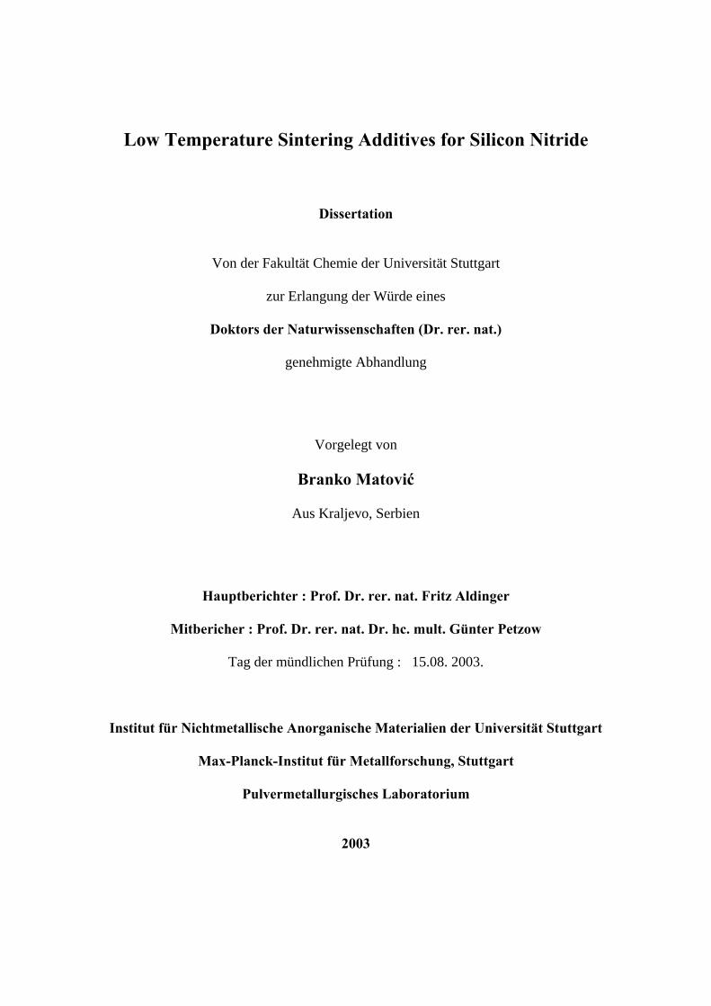
The α-structure belongs to the space group P31C, with 28 atoms per units cell (Fig. 2.1a). Its
lattice parameters are very sensitive to the oxygen content dissolved in the structure. This was
the reason why it was assumed that α-Si3N4 is an oxynitride with an oxide content of 0.9-1.48
wt% corresponding to the compositions [21]: Si11.5N15O0.5 and Si11.5Si2N15O0.5. In these
formulas some N atoms were replaced with O atoms and other N sites remained vacant.
Fig. 2.1a : Crystal structure of trigonal α-Si3N4. Taken from [2].
However, more detailed investigations showed that the oxygen content was less than that
required by the formulas given above [22]. Although oxygen is capable of replacing nitrogen
in some sites, it is not needed to form the α-structure. A refinement of the crystal structure of
an α-Si3N4 single crystal produced by a chemical vapour deposition process clearly
demonstrated that the bond length and site occupancy data do not indicate any oxygen in the
structure [23].
The atomic arrangement of the β-form is derived from the structure of the mineral phenacite
(BeSi2O4), with the oxygen atoms being replaced by nitrogen and the beryllium atoms by
silicon [24]. The unit cell of β-Si3N4 consists of Si6N8 units (Fig. 2.1b). While the literature
values of the structural parameters of this modification do not differ remarkably, the real
space group, whether centrosymmetric (P63/m) or acentric (P63), is still under debate [25]. In
the structure of space group P63/m, the silicon and nitrogen atoms lie in mirror planes at z=1/4
and z=3/4, normal to the c-axis [26]. In the case of the acentric space group, the nitrogen
atoms are slightly displaced from the mirror planes [27].

16
Fig. 2.1b : Crystal structure of hexagonal β-Si3N4. After [2].
During heating above 1400°C, the α-phase irreversibly transforms to the β-phase. β-Si3N4 is
the thermodynamically more stable phase at all temperatures and hence the transformation
from β- to α-phase is not possible [28]. The transformation is a reconstructive process
involving the breaking and reconstruction/formation of six Si-N bonds in each unit cell. This
transformation mechanism can proceed only in the presence of liquid phases, that lower the
activation energy for transformation. The value for the activation energy in the presence of the
liquid phase is about 405 kJ/mol-1 which is close to the Si-N bond energy (435 kJ/mol-1) [29].
The recently discovered γ-modification has a cubic structure, similar to the spinel structure
[30]. One silicon atom is coordinated tetrahedrally by four nitrogen atoms and two silicon
atoms have octahedral coordination by (six) nitrogen atoms (Fig. 2.1c.). This atomic
arrangement results in a density of 3.75 g cm-3, which is larger than that of α- and β-Si3N4
(3.19 g cm-3). In addition, the cubic modification has a hardness of 35.5 GPa, which is larger
than that of stishovite, a high pressure phase of SiO2 (33 GPa) and significantly higher than
the hardness of α- and β-Si3N4. Thus, the γ-modification is the third hardest material after
diamond and cubic boron nitride [29].

17
Fig. 2.1c : Crystal structure of γ-Si3N4. Taken from [2].
Silicon and Si3N4 have a high affinity to oxygen. Since the dimensions of the SiN4 tetrahedron
are very similar to those of SiO4 [30], some oxynitrides exist consisting of both, SiO4 and
SiN4 tetrahedra. The most common oxynitride is built up of SiN3O tetrahedra which are
linked together to form a three-dimensional network with the formula Si2N2O. Moreover,
silicon and oxygen atoms in β-Si3N4 can be replaced by Al and O atoms to form the so-called
Sialons with the formula Si6-zAlzN8-zOz, since the unit cell contains two Si3N4 units. The
number of replaced Al and O atoms is represented by the “z” value which can be varied
continuously from zero to about 4.2 [31, 32]. The Si3N4 ceramics with “z” values ≥ 0.5 belong
to the group of extended β-Si3N4 solid solutions (βSS) and all others with “z” values ≤ 0.5
belong to group of low β-Si3N4 solid solutions [2]. Similar extended solid solutions can be
formed with the addition of BeO or BeN [33]. However, these solid solutions (SiBeON) have
no practical use due to the toxicity of Be.
α-Si3N4 has an empty position with a coordination number of eight (7+1), which can be
partially occupied by ions with an atomic radius of about 0.1 nm. Occupation of the void
position causes a stabilization of the metastable α-Si3N4. The cations which can be
incorporated in the α phase are Li+, Mg+2, Ca+2, Y+3 and lanthanides with Z ≥ 60 [34].
Additionally, Si and N must be replaced by Al and O to obtain electroneutrality. The resulting

18
α-solid solutions are the so-called α-Sialons with the formula MxSi12-m-nAlm+nN16-nOn, where
m represents the number of (Si-N) bonds in α-Si3N4 which are replaced by (Al-N) bonds, n is
the number of (Si-N) bonds that are replaced by (Al-O) bonds, and x equals m divided by the
valency of the M cation. The charge discrepancy is compensated by M cations occupying the
interstices in the (Si,Al)-(O,N) network. Thus, α-Sialon can be regarded as a substitutional-
interstitial solid solution. The parameter “x” has a minimum value 0.33 for trivalent cations
and 0.3 for divalent cations since there is a miscibility gap between α-Si3N4 and α-SiAlON,
and the value of x cannot exceed 2 as there are only two interstitial sites in the unit cell [35].
Since the substitution range of α-solid solutions is smaller than for β solutions, the formation
of single phase α-Sialon is rather difficult. Deviations from the stoichiometry lead to the
simultaneous formation of β-solid solutions. The relationship between α- and β-Sialon is
given in Fig.2.2.
(Me,Al,Si)6(o,N)8 Mex(Si,Al)12(O,N)16
α-SiAlON
Me-NMe-O
Al4O6Al4N4
Si3O6 Si3N4β-SiAlON
Fig. 2.2 : Phase relationship in the M-Si-Al-N-O System [36].
An important feature of the SiAlON system is that the α- to β-SiAlON phase transformation
is fully reversible [37]. The α-phase is more stable at lower temperatures and can
accommodate metal oxides [38]. During the α- to β-SiAlON transformation metal oxides are
rejected to the intergranular regions according to the equation :
α-SiAlON⇔β-SiAlON + M-oxides rich intergranular liquid (2.1)

19
Additionally, the phase composition can be controlled by heat treatment procedures. 2.2 Preparative routes for silicon nitride powders
Since the occurrence of Si3N4 as a mineral in nature is very rare [39], all silicon nitride-based
ceramics must be produced synthetically. There are many different production routes for
Si3N4 powders, namely
⎯ direct nitridation of silicon
⎯ carbothermic reduction of silica
⎯ diimide synthesis
⎯ vapor phase synthesis
⎯ plasmachemical synthesis
⎯ pyrolyses of silicon organic compounds and
⎯ laser induced reactions.
All of these routes are based on four different chemical processes (Table 2-II) [40]. However,
only direct nitridation of silicon and diimide synthesis techniques are commercially viable
processes [41].
Table 2-II : Production of Si3N4 powders
Method Chemical process
direct nitridation 3 Si + 2 N2 ⇒ Si3N4
carbothermal nitridation 3 SiO2 + 6 C + 2 N2 ⇒ Si3N4 + 6 CO ↑
diimide synthesis SiCl4 + 6 NH3 ⇒ Si(NH)2 + 4 NH4Cl ↑
3 Si(NH)2 ⇒ Si3N4 + 2 NH3 ↑
vapor phase synthesis 3 SiCl4 + 4 NH3 ⇒ Si3N4 + 12 HCl ↑
The reaction conditions may be adjusted to provide powders of different crystallinity, α/β
ratio, morphology, particle size, particle size distribution and impurities. Typical chemical
analysis data and properties for commercial silicon nitride powders synthesized by different
techniques as mentioned above are given in Table 2-III.
The direct nitridation of silicon is performed in an atmosphere of N2, N2/H2 or NH3 at
temperatures above 1100°C but below the melting point of silicon (1410°C). The α-phase of

20
silicon nitride is the major product. Since the β-modification appears only in the presence of a
liquid phase, β-Si3N4 formation is favored either by the presence of impurity elements, which
are able to form low-melting eutectics, or by nitridation above the melting point of silicon
[42]. This reaction is highly exothermic and it is extremely difficult to control the temperature
using raw silicon. The heat of reaction can be used for the self-propagating synthesis of Si3N4
[43]. However, because of the uncontrolled reaction and a significant amount of β-phase in
the product, the self-propagation method can not be used for the production of high quality
Si3N4 powders. The process finally results in Si3N4 lumps which are then crushed and milled.
The quality of the final product depends on the purity of the raw material, the milling
procedure after nitridation and additional chemical purification of the powder.
The direct nitridation method can be carried out by a plasma chemical reaction, where
temperatures on the order of 5750°C are reached. The time of reaction is very short, resulting
in a high amount of amorphous Si3N4 and nano-crystallites of the α- and β-phases (about 20
nm). The grain size can be increased to 100 nm by an additional heat treatment process [44].
Table 2-III : Typical properties of Si3N4 powders produced by various processing techniques.
Technique
Direct
nitridation of
silicon
Vapor phase
synthesis
Carbotherma
l nitridation
Diimide
synthesis
Specific surface area
(g cm-2) 8-25 3.7 4.8 10
Oxygen content
(wt %) 1.0-2.0 1.0 1.6 1.4
Carbon content
(wt %) 0.1-0.4 - 0.9-1.1 0.1
Metallic impurities (wt %)
Σ Fe, Al, Ca 0.07-0.15 0.03 0.06 0.005
Crystallinity
(%) 100 60 100 100
α/(α + β)
(%) 95 95 95 85
Morphology
equiaxed
equiaxed +
rod-like
equiaxed +
rod-like equiaxed

21
Carbothermal nitridation was the earliest method to be used for Si3N4 production [45]. The
process involves the nitridation of carbon and silica precursor powder mixtures in a flowing
nitrogen atmosphere at temperatures in the range from 1400° up to 1500°C. The overall
reaction given in Table II proceeds via a number of intermediate reactions. The first step
involves the generation of SiO (gas) by the reduction of silica by carbon :
SiO2 + C → SiO(g) + CO(g) (2.2)
The CO produced in eqn. 2.2 is also capable of reducing further silica through the following
reaction:
SiO2 + CO → SiO(g) + CO2 (2.3)
The carbon within the system can in turn reduce the CO2 thereby regenerating CO as given by
eqn. (2.4):
C + CO2 → 2CO (2.4)
The SiO(g) produced by eqn. (2.2) or (2.3) reacts with N2 to form Si3N4 according to the
reactions given by eqn. (2.5) and (2.6):
3SiO + 3C + 2N2 → Si3N4 + 3CO (2.5)
3SiO + 3CO + 2N2 → Si3N4 + 3CO2 (2.6)
The characteristics of the Si3N4 powders resulting from carbothermic reduction depend on
many factors namely the C/SiO2 ratio, the nitrogen flow rate, reaction temperature, particle
size and specific surface area of silica and carbon and the impurities present. Although this
route has an advantage over direct nitridation because of the ready availability of the reactants
C and SiO2, compared to Si powder, the process has not yet been commercialized.
The diimide thermal decomposition fabrication process comprises three major steps : (a)
diimide synthesis, (b) diimide thermal decomposition and (c) crystallization. In the first step,
silicon tetrachloride (SiCl4) and ammonia (NH3) are made to react by liquid phase surface
reaction or vapor phase reaction to synthesize silicon diimide (Si(NH)2) and ammonium
chloride (NH4Cl). In the following step the Si(NH)2 is thermally decomposed at a temperature

22
of about 1000°C to obtain an amorphous silicon nitride powder. During the final step, the
amorphous powder is crystallized in a temperature range of 1300-1500°C to form the α-Si3N4
powder [46]. This powder is characterized by sub-micron equiaxed particles containing a
large amount of α-phase.
The vapor phase synthesis takes place between different gaseous species in the temperature
range from 800° up to 1400°C. Usually, the starting materials are SiCl4 and ammonia which
react to form amorphous Si3N4. Crystallization of the amorphous powder is carried out at
temperatures 1300-1500°C. Deagglomeration is also a necessary step to be carried out.
Synthesis of powders by lasers is a useful technique for making nano-size (10-100 nm)
powders starting from gaseous or volatile mixtures [47] and is based on the absorption of
infrared laser energy e.g., (10.6 µm wavelength for CO2 laser) which is converted into
vibrational modes of the reactant gases that produce very high temperatures (above 1000°C)
for a short total reaction time (0.1 s or less). These conditions are necessary for the initiation
of a chemical reaction the final result of which is the formation of the powder. Due to the
coherent nature of the laser source, a well-localized reaction zone can be defined.
The grown particles have a spherical morphology, small size, narrow size distribution and
their stoichiometry can be precisely controlled by adjusting the main process parameters such
as laser intensity, pressure in the reaction cell, reactant flow rates, reaction gas ratio and
temperature of the reaction [48].
All these powders are useful in structural ceramic applications.
2.3 Processing techniques of silicon nitride ceramics
The high degree of covalent bonding makes it very difficult to produce pure dense Si3N4
ceramics by classical sintering (simple heating of powder compacts). The main reason for this
is that the diffusion of silicon (at 1400°C DSi ≈ 0.5 x 10⁻¹⁹ m2⋅s-1) and nitrogen (at 1400°C DN
≈ 6.8 x 10⁻¹⁰ m2⋅s-1) in the volume or at the grain boundaries of Si3N4 is extremely slow [10].
As densification by sintering requires mass transport via volume or grain boundary diffusion
and since such diffusion is a thermally activated process, a higher sintering temperature would
result in a highly dense material [49]. However, at high temperatures Si3N4 starts to dissociate
[50]. Therefore, sintering additives are utilized as a possibility to promote liquid phase
sintering and thus enhance volume or grain boundary diffusion. As a consequence, many
different sintering techniques have been developed:

23
⎯ Reaction bonding RBSN
⎯ Hot pressing HPSN
⎯ Hot-isostatic pressing HIPSN
⎯ Gas-pressure sintering GPSN
⎯ Pressureless sintering SSN
One common densification method is the nitridation of silicon compacts, leading to reaction-
bonded silicon nitride (RBSN) materials. By this method, complex shapes can be produced
using various ceramic forming methods (slip casting, injection molding, die pressing, isostatic
pressing) with low costs. However, the process leads to a material of limited density (about
70-88%) resulting in poor mechanical properties. Because of the residual porosity the strength
of RBSN is relatively low. Furthermore, the pore structure leads to high oxidation rates and to
small erosion resistance [42, 51]. Thus, low densities and pore structure limit the range of
possible applications of RBSN materials.
Hot-pressing of pure silicon nitride powder at high temperatures does not result in full density
and leads to the production of porous materials with properties similar to those of RBSN [52].
In spite of this, the first dense Si3N4 ceramic was that accomplished by hot pressing Si3N4
powders containing MgO as sintering additive [3]. Such kind of hot-pressed Si3N4 ceramics
(HPSN) is a high strength material, which can be used at temperatures up to 1000°C without a
decrease in strength. Because of high cost and difficulties to machine the components, hot-
pressing, today, has limited use for the production of simple shaped parts and low quantities.
Another method is to apply isostatic pressure instead of uniaxial pressure, i.e. hot-isostatic
pressing (HIPSN). During this process a high gas pressure is applied to consolidate a powder
compact or to remove the residual porosity from presintered bodies. The uniform manner of
applying the high pressure results in fully isotropic material properties. The possibility to use
much higher pressures than in uniaxial hot-pressing leads to an enhancement in the
densification of the products. Thus, fully dense ceramic parts can be produced from powders
of lower sintering activity and with smaller amounts of additives as compared with unaxial
hot pressing. Three different routes are used in order to produce fully dense ceramics by the
HIP technique: (a) HIP densification of Si3N4 powder compacts, (b) HIP densification of
reaction bonded Si3N4 and (c) HIP densification of normal sintered Si3N4. All these
techniques lead to materials which combine excellent mechanical and thermo-mechanical
properties. The main disadvantage of this method is its high cost. The most common

24
sintering/densification method for high-strength Si3N4 ceramics is gas pressure sintering
(GPSN). This method allows sintering of complex-shaped parts with medium cost. However,
the most economical method is to sinter Si3N4 powder compacts with additive under 0.1 MPa
N2 at 1700°-1800°C, i.e. pressureless or normal sintering (SSN). The powder mixtures (Si3N4
plus additives) are compacted to required shapes by various shaping methods. Complex-
shaped components of dense Si3N4 which require little machining remain after sintering.
Because the highest sintering temperature is restricted by thermal dissociation of Si3N4 [53],
relatively large amounts of additives are necessary to fabricate high density materials.
2.4 Sintering
2.4.1 Basic theory of liquid phase sintering
Liquid phase sintering (LPS) is the sintering process in which a part of the material being
sintered is in the liquid state. This is a conventional technique, that has been used to
manufacture ceramics for many centuries [54]. LPS is important for systems which are
difficult to densify by solid state sintering, i.e. ceramics that possess a high degree of covalent
bonding e.g., (Si3N4 and SiC). The liquid is normally produced from a mixture of at least two
powders, a major component and an additive. On heating of the mixture, the additive melts or
reacts with a small part of the major component to form a eutectic. The amount of liquid
produced at the sintering temperature is usually maintained in the range of 5-15 vol%. In most
systems, the liquid does not change its volume. Due to persistence of the liquid throughout the
sintering process, this condition is referred to as persistent liquid-phase sintering. In other
systems, the liquid may be present over a major part of the sintering process and then
disappears by different ways namely
1. incorporation into the solid phase (formation of a solid solution),
2. crystallization of the liquid or devitrification of glassy phase and
3. evaporation.
All these situations are referred to as transient liquid-phase sintering. Transient LPS is a very
important technique in the sintering of Si3N4 with additives for producing dense Si3N4 based
ceramics.
2.4.1.1 Factors controlling liquid phase sintering
Liquids with a low surface tension readily wet solids, giving rise to small contact angles,

25
while liquids with a high surface tension show poor wetting, forming larger contact angles
(Fig. 2.3). At the molecular level, if the cohesion between the liquid molecules is smaller than
the adhesion between the liquid and solid, the liquid has a tendency to wet the solid. The
degree of wetting is quantified by the equilibrium contact angle that forms between the liquid
and the solid and is defined in Fig. 2.4. If the energies of the liquid/vapor, solid/vapor and
solid/liquid interfaces are γlv, γsv and γsl respectively, then a simple balance of forces indicates
equilibrium according to the equation given below
γsv = γsl + γlv⋅cosθ (2.7)
Hence, higher values of γsv and lower values of γsl and/or γlv promote wetting. This equation,
derived by Young and Dupre [55], shows that a necessary condition for liquid-phase sintering
to occur is that the contact angle must lie between 0 and 90° (to stay consistent with the
drawings). For higher contact angles (>π/2), the liquid will bead up in the pores and the
sintering can occur only by the solid-state mechanism. The contact angle also has an
important effect on the magnitude and nature of the capillary forces exerted by the liquid on
the solid grains [56].
θ < 90° - good wetting
θ > 90° - poor wetting
θ = 0° - complete wetting
Fig. 2.3 : Wetting behavior between a liquid and a solid.

26
interfacial tension
Fig. 2.4 : Equilibrium contact angle between a liquid and a solid.
The other necessary condition for LPS is that the liquid distributes itself to cover the surfaces
of the particulate solids. The complete penetration and separation of the grain boundary by the
liquid depends on the dihedral angle which is defined as the angle between the solid/liquid
interfaces as sketched in Fig. 2.5 :
γgb = 2 γsl cos (ψ/2) (2.8)
The grain boundary energy (γgb) must be less than twice the solid/liqid surface energy γsl [57].
Thus, high values of γgb and low values of γsl are desirable. The microstructural features
obtained for various values of the dihedral angle are listed in table 2-IV. For ψ = 0, the liquid
completely penetrates the grain boundaries and no solid/solid contact exists. As ψ increases,
the penetration of the liquid phase between the grains decreases and the number of solid/solid
contacts increases.
Fig. 2.5 : Equilibrium dihedral angle between a grain and the liquid phase.

27
Table 2-IV Microstructural features of liquid-phase sintering as a function of dihedral angles (ψ).
Dihedral angle
(ψ) Microstructure
0° isolated grains separated by liquid phase
0-60° partial penetration of grain boundaries by liquid along the three-grain edges
60-120° isolated pockets of liquid at extended four-grains junctions
≥ 120° isolated liquid phase at four grain junctions
Surface tension between solids and liquids generates capillary forces, which may give rise to
very strong attractive forces among neighboring grains. The contact stress that is generated
upon grain impingement, in combination with the lubricating potential of the liquid, enhances
the dissolution of solids leading to rapid particle rearrangement and densification. The main
processing parameters, such as particle size, green density, sintering temperatures, time and
atmosphere, have large effects on the material characteristics obtained by liquid-phase
sintering. All of these factors contribute to the complexity and difficulty in understanding
liquid-phase sintering mechanisms.
2.4.2 Basic mechanisms of liquid-phase sintering
The plausible mechanisms for liquid-phase sintering have been described in detail by Kingery
[58, 59], Petzow et al. [60] and German [61]. In order to understand these mechanisms, a
number of experimental and theoretical investigations were made. All of them come to the
same conclusion that the LPS process occurs in three stages, so that there is some degree of
overlapping between the theories. Classically, the following sequence of sintering stages is
considered to be prevailing:
1. Particle rearrangement,
2. Solution-reprecipitation and
3. Solid-state or skeleton sintering.
2.4.2.1 Particle rearrangement
Rearrangement is the dominant process in the first stage. After a liquid has been formed
within the powder compact, rapid densification occurs, due to liquid capillary forces via the

28
movement of the solid particles from their initial positions towards an arrangement of random
dense packing and a higher degree of space filling. Rearrangement is also an effective
densification phenomenon during the whole shrinkage period, even during solid state
sintering [62].
This process is rapid. However, except for large liquid contents, it cannot lead to complete
densification. Many parameters, such as the amount of liquid, its viscosity, green density,
wetting, sintering temperature etc. strongly affect this stage. Kingery’s model gives an
empirical approach in which the rate of densification corresponds approximately to the
viscous flow and follows a relation as given below:
∆L/L0 ≈1/3 ∆V/V0 ≈ t1+y (2.9)
where ∆L is the change in length and L0 the original length, ∆V and Vo correspond to the
change in volume and initial volume respectively. The exponent 1+y is slightly greater than
unity due to the fact that pore sizes decrease and the driving force increases during the
process, while at the same time t, the resistance to rearrangement, increases from the initially
pure viscous flow. There are other approaches to analyzing the rearrangement during liquid-
phase sintering, such as analysis of the capillary forces between particles separated by a liquid
layer. All of these models are quite complex and calculations are very cumbersome.
2.4.2.2 Solution-reprecipitation
In the second stage, the rearrangement efficiency decreases significantly and the solution-
precipitation process becomes dominant.. Capillary forces generate a difference in the
chemical potential at the points of contact between grains when compared to the areas that are
not in contact. This chemical potential gradient induces the dissolution of atoms at the contact
points and their reprecipitation away from the contact areas, which leads to shrinkage and
densification. The necessary condition for the process to occur would be a finite solubility of
the solid in the liquid and good wetting ability of the liquid. In addition to densification,
coarsening can occur simultaneously by the dissolution of the smaller particles and their
reprecipitation on the larger particles. The dissolution and reprecipitation of dissolved
materials contributes to the microstructural development, shape accommodation and grain
growth.
There are two theories explaining the evolution of densification during liquid phase sintering,
namely the contact flattening theory and the pore filling theory. The fundamental difference
between these theories lies in whether the grain shape is changed or not during densification

29
of the powder compact. Kingery [58] proposed that shrinkage and hence densification is
achieved by the matter transport from the contact area between grains to the off-contact neck
region, analogous to solid-state sintering. The contact regions between particles become flat.
This process results in a continuous change in grain shape until there is a complete
elimination of the pores. A number of investigations were confirmed this theory [59, 63, 64,
65, 66].
Another mechanism of densification has been proposed according to microstructural
observations [67]. In this model, an isolated pores were eliminated by the instantaneous filling
with liquid [68, 69]. Upon prolonged sintering, the liquid pocket is eliminated by
microstructural homogenization due to material deposition of the grains at the concave
surfaces and growth toward the liquid pocket center. Once the the pore filling occurs, the
grains grow into the liquid pocket, resulting in microstructural homogenization [70, 71, 72].
This solution-precipitation process is the classic Ostwald ripening process [73]. Dissolution of
the small grains and precipitation away from the contact points causes the centers of the larger
grains to approach each other, resulting in shrinkage. Ostwald ripening is thought to
accompany the densification process.
2.4.2.3 Solid-state or skeleton sintering
The last stage is referred to as solid-state controlled sintering. The overall shrinkage or
densification rates are significantly reduced due to formation of a rigid skeleton that inhibits
further rearrangement [74, 75]. Coarsening is the dominant process. The three stages of
liquid-phase sintering are sketched as a sintering curve in Fig. 2.6. Particle rearrangement is
Stage III-Solid state sintering
Stage II-solution-precipitation
Stage I-rearrangement
IIIIII
Rel
ativ
e de
nsity
S intering timeFig. 2.6 : Schematic diagram illustrating the three stages of liquid-phase sintering on a typical sintering curve.

30
the process occurring the fastest on a time scale of minutes [76]. The solution-reprecipitation
process and skeleton sintering depend on diffusion through the liquid and solid, respectively,
and hence, are slower in comparison to I stage (particle rearrangement)
2.5 Liquid phase sintering of silicon nitride
Many manufacturing techniques such as pressureless sintering, gas-pressures sintering, hot-
pressing and hot-isostatic pressing, that are employed for obtaining dense Si3N4 bodies, are
related to liquid-phase sintering. The sintering behaviour of Si3N4 ceramics is affected directly
by the characteristics of the liquid phase present. If the liquid fulfills the conditions of good
wettability and solubility of Si3N4, densification can be described according to the standard
mechanisms of liquid phase sintering: particle rearrangement, solution-precipitation and
particle coalescence (or grain growth). During the sintering of α-Si3N4, the phase
transformation to β-Si3N4 is an additional phenomenon interelated with this sequence.
2.5.1 Densification
The densification of Si3N4 is negligible before the formation of the liquid. Once the liquid is
formed, densification takes place through particle rearrangement, due to capillary forces as
detailed above. The extent of particle rearrangement is mainly dependent on the size and
shape of particles and amount and viscosity of the liquid phase. The rearrangement process
ceases when interparticle contacts are formed that prevent the system from further
densification. After formation of the particle bridges, however, the solution-precipitation
process starts resulting in the collapse of the bridging. This leads to densification by
secondary rearrangement and center-to-center approach [62]. The driving forces for the
second stage are the higher solubility at the contact points of the particles and the differences
in the chemical potentials between small and large particles, that lead to dissolution of small
particles and precipitation of matter on the surface of larger particles.
There are two possible rate controlling steps during solution-precipitation, namely surface
reaction and solute diffusion [77]. Which process would be dominant can be decided if the
activation energies are obtained from the reaction kinetics. In case of the surface reaction, the
activation energy ranges from 290 to 435 kJ/mol. This value matches the Si-N bond energy
[78]. For the solute diffusion mechanism, the reaction activation energy lies in the range of
580-730 kJ/mol. These values correspond to the energies of Si diffusion in various silicate

31
glasses [79]. In addition, the reaction is not sensitive to changes in either the liquid
composition or the liquid content for the surface reaction controlled mechanism when
compared to the solute diffusion mechanism.
2.5.2 Phase transformation
The α-Si3N4 phase is thermodynamically unstable during sintering (e.g. at 1400-2000°C and
0.1 to 100 MPa N2 pressure [2]) and shows a tendency to transform into the more stable β-
Si3N4. The transformation is a reconstructive one [80]. This process involves the breaking and
reforming of Si-N bonds. The nearest neighbour atoms remain the same in both the
crystallographic forms [81]. The relations of α- and β-Si3N4 with α- and β-SiAlON are shown
in Fig.2.7. While the β→α-Si3N4 transformation has not been observed, the transformation
between α- and β-Sialon is reversible [38].
Phase transformations play an important role for microstructural development. Different
microstructures are possible depending on the location where reprecipitating of solute occurs.
This location of reprecipitation can be either new β-nuclei generated by supersaturation [82]
or the pre-existing β-grains, which coexist with the α-phase in the starting powders. If the
raw powder contains a low concentration of β-grains, high supersaturation in the liquid phase
is create
like β-g
equiaxed
α-Si3N4
α-SiAlON
Fig. 2.7 : Phase transformation in Si3N4-Sialon
d locally resulting in a spontaneous nucleation and cry
rains. The precipitation on pre-existing β-grains r
structure [83].
β-Si3N4
β-SiAlON
-additive system.
stallization of idiomorphic rod-
esults in a coarser and more

32
2.5.3 Grain growth
Growth of Si3N4 grains is commonly observed during sintering. The driving force orginates
from the curvature difference between grains [84]. Si3N4 prism planes are more stable
compared to basal planes. However, basal planes grow faster than the prism planes resulting
in a needle like-grain morphology. The difference in growth rates is related to an energetically
more favourable attachment of a surface nucleus on the basal plane [2]. The growth kinetics
can be described by the following formula :
(2.10) ktGG no
n =−
where G is average grain size, Go the initial grain size, k the kinetic constant, and t the
observation time. The grain growth occurs in order for it to reach a steady state. When the
grains grow in a steady state, the normalized grain-size distribution is invariant with time,
independent of the initial grain-size distribution, and the exponent n is 3 for diffusion control
[85] and 2 for interface-reaction control [86].
2.6 Microstructure
After the liquid phase sintering the microstructure of dense Si3N4 consists mainly of β-Si3N4
and of mostly amorphous grain-boundary phases. During cooling, the liquid solidifies to
amorphous or partially crystalline secondary phases, which are located either at the grain
boundaries in the form of thin layers or at triple junctions (Fig. 2.8). This intergranular phase
strongly affects the mechanical properties, especially at high temperatures. The thickness of
Fig. 2.8 : Typical microstructure of a liquid-phase sintered Si3N4 ceramics [schematic (a) and SEM micrograph (b)]. 1- Si3N4 matrix grains, 2-crystalline secondary phase, 3-amorphous residue at triple junctions and grain boundaries.

33
the grain boundary film depends rather on the types of additives than on the amount of liquid
phase. An increase in the latter leads only to an increasing volume of the triple points [87].
A typical feature of sintered Si3N4 ceramics is the morphology of the Si3N4 grains. Residual
α-grains are equiaxed. The β-phase exhibits an elongated grain stucture with an aspect ratio
(ratio of length to thickness) usually in the range of 5 to 10 [88, 89].
The microstructural development is controlled mainly by the Si3N4 starting powders, the
additives used and the sintering parameters.
2.7 Sintering additives
The desirable properties of Si3N4 ceramics are achieved only in a fully dense material.
However, it is difficult to densify Si3N4 into a usable form without the use of sintering
additives as discussed previously. Thus, using additives is a prerequisite for obtaining dense
Si3N4 ceramics. The type and amount of sintering additives determine the liquid forming
temperature, the onset of densification and its rate during sintering [11]. They also define the
morphology of the β-grains and the characteristics of the grain-boundary phase, which in turn
controls the high-temperature properties. The role of the additive can be expressed by the
following reactions:
(Si3N4 + SiO2 + impurities) + additive [starting powder]
↓ sintering temperature
β-Si3N4 + liquid (SiO2 + additive + Si3N4) [sintering]
↓ cooling
β-Si3N4 + amorphous/crystalline phases (SiO2 + additive) [final product]
Silica at the surface of Si3N4 powder particles reacts with the sintering additive producing a
liquid phase. The melting temperature of the additive-SiO2 composition and the amount and
viscosity of the resulting liquid phase are closely connected with the SiO2 concentration on
the Si3N4 particle surfaces, the amount of dissolved α-Si3N4 in the liquid and the impurity
content of the starting powder. The liquid promotes densification through a solution-
reprecipitation mechanism. Upon cooling, the liquid solidifies and forms the residual
intergranular glassy phase and possibly secondary crystalline phases [90], as already
explained in 2.6.

34
Different types of additives have been employed for the pressureless and pressure-assisted
sintering of Si3N4 ceramics [11, 49, 2, 91, 92] :
(a) Binary metal oxides or ternary oxides which do not form solid solutions with Si3N4. They
remain as an amorphous or partially crystallized silicate grain-boundary phase. The more
thoroughly investigated additives are MgO, Y2O3, Al2O3, La2O3, CeO2, Yb2O3, ZrO2, Li2O,
MgAl2O4, ZrSiO4.
(b) Oxides or non-oxides or their mixtures which form solid solutions with Si3N4, like BeO,
AlN, Al2O3 + AlN, Y2O3 + AlN, ZrN, ZrC, Mg3N2. They also form liquid phases with silica
from the Si3N4 surface. α-Si3N4 is dissolved in the liquid and re-precipitated as β-Si3N4 solid
solution which has incorporated a certain amount of the starting additive. During sintering,
the amount and composition of the liquid phase changes gradually and it has been envisaged
to be possible to produce a material without an amorphous intergranular phase [93, 94].
The eutectic temperatures of the commonly used oxide systems for the liquid-phase sintering
of Si3N4 are listed in Table 2-V. However, it has been indicated that the presence of N lowers
these eutectic temperatures further [95]. The alkali and alkaline-earth oxides have a low
melting point and the viscosity of the resulting liquid is also low. The solution-diffusion-
precipitation processes are enhanced. In case of rare-earth oxides, the melting temperatures
with SiO2 are higher and densification rates are lower [96].
Table 2-V : Oxide additives used for the densification of Si3N4.
Temperature of liquid formation, °C Additive
MxOy
Silicate
MxOy-SiO2
Oxynitride
MxOy-SiO2-Si3N4
Li2O 1030 1030 [97]
MgO 1543 1390 [97]
Y2O3 1650 1480 [98]
CeO2 1560 1460 [97]
ZrO2 1640 1590 [97]
CaO 1435 1435 [97]
Al2O3 1595 1470 [98]
The viscosity of the liquid phase has a strong effect on the grain morphology which in turn
affects the mechanical properties. Materials processed with additives that form liquid phases
of higher viscosity consist of grains with a high aspect ratio [99], and as a consequence,

35
exhibit better mechanical properties both at room temperature and at high temperatures. A
good example for different behavior of sintering additives are magnesia and yttria,
respectively. The temperature of liquid formation for the MgO-SiO2-Si3N4 system is lower by
nearly 100°C in comparison with the Y2O3-SiO2-Si3N4 system (Table 2-V). The MgO melt
has also a lower viscosity than Y-SiAlON melts. The solubility of Si3N4 in a magnesium-
containing melt is higher than in a yttrium-containing one. Therefore, the effect of MgO
additive as a sintering aid is more beneficial. On the other hand, the higher viscosity and
melting point of yttrium-containing liquid allow the sintered product to retain its
thermomechanical properties at higher temperatures.
From Tables 2-V and 2-VI, it is clear that the sintering behaviour is improved with increasing
amount of additives. However, high additive amounts above 20 vol% for certain
Table 2-VI : Summary of sintering studies of Si3N4 at atmospheric pressure with magnesia
and yttria additives and their compounds [100].
Additive
Sintering temperature
(°C)
Sintered density
(% Th. D.)
5 mol% MgO 1500-1700 86
10 mol% spinel (MgO⋅Al2O3) 1650-1900 96
5 wt% MgO + 0.15 wt% CaO
+ 0.8 wt% FeO +
4 wt% Y2O3 + 2 wt% Al2O3
1750 95
10 wt% MgO⋅Al2O3 1600-1750 97
5 wt% MgO + BeO + CeO2 1800 97
4 mol% Y2O3 +
2 mol% Al2O31725 Not mentioned
10 wt% Y2O3 +
3 wt% Al2O31600-1750 98
3.5-20 wt% Y2O3 +
20 wt% Al2O31750-1825 100
10 mol%Y2O3 +
20 mol% SiO21750 90
4-17 wt% Y2O3 +
2-4 wt% Al2O31500-1750 95

36
thermodynamically less stable additives and/or high oxygen content of the starting powders
can cause the formation of gas bubbles by increasing in the formation of gaseous SiO [101].
Also, the ratio of the components in the additive has a major influence on the evolution of the
microstructure. In case of yttria and alumina additives, with decreasing ratio of Y2O3 to
Al2O3, the microstructure becomes finer with a lower aspect ratio [102].
During sintering, the amount and composition of the additives may be changed due to
interaction with the atmosphere. Using nitrogen alumina can be partially reacted to AlN
which is very easily dissolved in the Si3N4 lattice causing a shift of the liquid phase
composition and the structural properties of the Si3N4 ceramics. At high sintering
temperatures, the alkali and alkaline-earth oxides are unstable and evaporate. On the other
hand, rare-earth oxides are more stable than the other additives [103, 104], and even during
long sintering times no change in their concentration has been found.
2.8 Mechanical properties of Si3N4 materials
Typical data for the properties of hot-pressed and pressureless sintered Si3N4 are presented in
Table 2-VII. It can be inferred from the given data that Si3N4 possesses high strength, good
thermal-shock resistance due to the low coefficient of thermal expansion and relatively good
resistance to oxidation compared to other high-temperature structural materials [105].
Table 2-VII : Typical properties (at room temperature) for advanced hot-pressed and
pressureless sintered silicon nitrides [106].
Property Hot pressed Si3N4 Pressureless sintered Si3N4
Density (g/cm3) >3.20 3.20
Thermal conductivity (W/mK) 29.3 15.5
Flexural strength (MPa) 1200
Compressive strength (MPa) 4500 4000
Thermal expansion (10-6/K) 3.2 3.4
Young’s modulus (GPa) 320 280
Toughness-KIc (MNm3/2) 8.3 5.4
The mechanical property of Si3N4 ceramics depend on pores present, cracks and inclusions.
Among these factors, porosity has been demonstrated to have a pronounced effect on strength.

37
Fig. 2.9 shows the relationship of the relative density and strength of pressureless sintered
Si3N4 with yttria and alumina additives.
Fracture toughness differs mainly with variations in the microstructure. The grain shape and
the size and phase composition of the grain-boundary phase have a strong influence. High
fracture toughness of Si3N4 based ceramics could be explained on the basis of similar
toughening mechanisms as in whisker reinforced composite materials (grain bridging, pull-
out, crack deflection, and crack branching [107, 108, 109]). However, these toughening
mechanisms are only active when the dominant fracture mode is intergranular.
The ratio of transgranular to intergranular fracture depends on the strength of both
intergranular-phase and Si3N4 grains. A material with higher toughness has a weaker grain
boundary. On the other side, the strength of the grain-boundary phase is connected with the
local residual stresses [110]. When the thermal expansion coefficient of the grain-boundary
phase is higher than that of the Si3N4 grains, the grain-boundary phase is under tensile stress
and the fraction of intergranular fracture is high. As a consequence, the fracture toughness
Fig. 2.9 : Dependence of the strength of pressureless sintered Si3N4 on the density. After[106]
increases. In contrast, ceramics with a grain boundary phase under compression have low
fracture toughness because of a higher amount of transgranular fracture [111].
A comparison of the flexural strength values of pressureless sintered Si3N4 at ambient and
high temperature is given in Table 2-VIII.

38
Table 2-VIII : Flexural strength data of pressureless sintered Si3N4. After [100].
Flexural strength Additive
room temperature
(MPa)
high temperature
(MPa)
10 mol% spinel 706 -
Y2O3, Al2O3 412 -
15 wt% (MgO + Al2O3) 351 -
3.5-20 wt% Y2O3 + 0-20 wt% Al2O3 700 455 (at 1200°C)
5 wt% (MgO + BeO + CeO2) 827 428 (at 1200°C)
15 mol% Y2O3 473 -
3-10 wt% Y2O3 450 -
3-10 wt% CeO2 520 -
3.3-7.2 mol% CeO2 + 12.8-20 mol% SiO2 709 393 (at 1200°C)
4.3 wt% Y2O3 + 3.6 wt% SiO2 826 338 (at 1200°C)
4 wt% CeO2 + 4 wt% SiO2 778 356 (at 1200°C)
6.3 wt% La2O3 + 3.6 wt% SiO2 729 412 (at 1200°C)
5.9 wt% Sm2O3 + 3.6 wt% SiO2 696 455 (at 1200°C)
7.5 mol% Y2O3 + 7.5 mol% Pr6O11 800 >800 (at 1300°C)
1 wt% Al2O3 + 3 wt% CeO2 750 -
2 wt% Al2O3 + 5 wt% Y2O3 860 -
5-10 wt% Y-Al-garnet 779 -
13.4 wt% ZrO2 + 2.2 wt% Y2O3 + 4.1 wt% Al2O3 422 463 (at 1200°C)
The amount, composition and degree of crystallization of the grain boundary phase are the
key factors for a successful development of Si3N4 ceramics for applications at elevated
temperatures. Additives which result in amorphous silicate phases with a low softening point
and low viscosity, such as alkali and alkaline earth oxides and Al2O3 and AlN, generally have
a high strength at room temperature. However, due to a low softening point, they are not well
suited for high temperature applications. Refractory intergranular phases with a higher degree
of crystallinity were obtained by yttria or other rare earth oxides as sintering additives [112,
113]. The high temperature properties of Si3N4 with rare-earth oxides as sintering additive
increase with decreasing ionic radii. The most superior high temperature properties are found

39
with Lu2O3 as sintering additive due to the presence of Lu2Si2O7 and Lu4Si2O7N2 as the grain
boundary phases [2].
The presence of nitrogen in silicate glass helps to produce hard and refractory grain
boundaries in the sintered product, thus improving its high temperature properties.
2.9 Thermal properties
Thermal conductivity is one interesting property of Si3N4 which combined with the excellent
mechanical properties make it a serious candidate for high-performance substrates [114].
Firstly, Haggerty and Lightfoot pointed out Si3N4 as a material with potentially high thermal
conductivity at room temperature [115]. Calculation shows that the entrinsic thermal
conductivity of β-Si3N4 single crystals is 320 W m-1 K-1 which is similar to the thermal
conductivity of SiC and AlN that have been successfully fabricated for commercial uses as
high thermal conductivity substrates and heatsinks [116]. However, relatively poor thermal
conductivity values, ranging from 20 to 70 W m-1 K-1 have been reported for Si3N4 ceramics
fabricated by reaction bonding [11], chemical vapor deposition [117], hot pressing and hot-
isostatic-pressing methods [118]. Very recently, Watari et al. fabricated a Si3N4 with thermal
conductivity value of 155 W m-1 K-1 by a novel processing technique termed grain-orientation
technology [116].
It is postulated that heat flow in hexagonal β-Si3N4 is different depending on the crystal axis.
In single crystal measurements it was shown that the conductivity along the c-axis is about
three times higher than that along the a-axis [119].
The thermal conductivity of Si3N4 ceramics depends strongly on the amount of Al impurities
and/or sintering additives because the incorporation of Al and O in the β-Si3N4 structure
reduces the thermal conductivity of the grains due to the reduced free path of phonons. Thus,
Al-free sintering additives are a precondition for the production of Si3N4 ceramics with high
thermal conductivity [2]. Internal defects in the grains [120] and increasing grain boundary
thickness were also found to decrease the thermal conductivity [121].
From a commercial point of view, it is very important to fabricate high thermal conductivity
Si3N4 ceramics by conventional sintering technique such as pressureless sintering. Seeding
combined with careful control of grain boundary composition can be one processing strategy
for this purpose. In addition, microstructure design for harmonizing high thermal conductivity

40
with good mechanical and electrical properties is also very important for the widespread use
of Si3N4 ceramics as a high thermal conductivity material [114].
2.10 Oxidation resistance of Si3N4 materials
As silicon nitride materials are used in oxidising environments, a number of studies have been
made on the oxidation of Si3N4 sintered with different additive systems [122, 123, 124, 125,
126, 127, 128].
Si3N4 is thermodynamically unstable in air. However, it is protected against further oxidation
by a thin surface layer of amorphous silica. Generally, there are three oxidation reactions,
which can cause oxidation of Si3N4:
Si3N4(s) + 3O2 → 3SiO2(s) + 2N2 (2.11)
Si3N4(s) + 3SiO2 → 6SiO(g) +2N2 (2.12a)
2 Si3N4(s) + 3O2 → 6SiO(g) + 4N2 (2.12b)
Reaction 2.11 forms a dense oxide layer that inhibits further oxidation and is therefore called
passive oxidation. Once an oxide layer is formed the rate of further reaction is controlled by
the oxygen diffusion through this layer and shows a parabolic rate law:
(∆G/A)2 = Kpt (2.13)
where (∆G/A) is the weight gain per unit area, t is the oxidation time and Kp is the parabolic
rate constant. Reactions 2.12 a and b occur at low oxygen partial pressures. The reactions
proceed in a continuous manner. This is the so-called active oxidation which does not form a
protective layer and thus proceeds as long as the oxygen (or SiO2) is not completely
consumed.
There are a number of other parameters which influence the oxidation. The presence of
impurity elements increases the rate of oxidation if they are incorporated into the amorphous
layer, where they are normally concentrated by segregation and increase the oxygen
diffusivity [129]. An opposite effect is observed if these elements promote the crystallization
of oxide phases on the surface, resulting in a lower oxygen diffusivity and a decreased
oxidation rate. Oxidation also increases if crystalline secondary oxynitride phases oxidize.
This reaction involves a significant increase of volume as in the case of some silicon yttrium-

41
oxynitrides. The volume increase can produce surface flaws thereby creating fresh surfaces
[130].
2.11 Applications
Si3N4 based materials, as described previously, have good mechanical and thermal properties,
which are well-balanced compared to other ceramic materials. They are lighter and possess
better heat resistance and wear resistance than metals. For example, SiC is an excellent heat
conductor, however, its toughness and thermal shock resistance are behind that of Si3N4.
Toughened zirconia can exhibit much higher strength and toughness as Si3N4, but its high
temperature properties and thermal shock resistance are poor. Different types of Si3N4
materials can be produced by changing the starting powders, types and amounts of additives
and manufacturing processes. These properties make them prime candidate materials for
structural applications at ambient and high temperatures. Table 2-IX presents the time
evolution of Si3N4 with regard to its application [2].
Table 2-IX : Time evolution of Si3N4 from chemical compound to an advanced ceramic.
Year Development-with regard to Si3N4
1830 Diimide synthesis 1859 Direct nitridation 1896 Carbothermal reduction of SiO2 1910 Chemical formula 1950 Reaction bonded parts 1955 First application as refractories 1957 Crystal structure 1961 Fully dense bodies (hot pressed material) 1971 β-SiAlON 1976 Liquid phase sintering (LPS) 1977 Gas pressure sintering (GPS) 1978 α-SiAlON 1979 Cutting tools 1981 Components for engines 1985 Turbo charger rotors 1993 Valves 1996 Components for aircraft 1999 γ-Si3N42000 Valve plate for common rail systems 2001 Cooking plates

42
Further improvement of the material properties, lower cost and collaboration between ceramic
producers and industrial use is expected to create new fields of applications with a higher
acceptance of Si3N4 on the market.
2.12 Motivation
In spite of the excellent properties of Si3N4 based ceramics, their widespread use is still
limited, the main reason being the cost factor with respect to:
1. Raw materials (Si3N4 powders)
2. Raw materials (additives)
3. Production processes
The motivation for this work is to improve the economic viability of silicon nitride products
by way of lowering the cost of starting materials and lowering the sintering temperature.
Additives that satisfy these criteria are from the Li2O-Y2O3 and Li2O-Al2O3-SiO2 systems.
The reasons for their suitability as sintering additives are as follows:
1. Lithia and yttria have been effective single component additives. Experimental evidence
confirms this assumption [131]. Hence, a mixed oxides from both system should as well
be useable as an additive.
2. Li2O reduces the viscosity of the liquid phase and thus minimises the total amount of
additive needed for sintering.
3. Yttrium is insoluble in Si3N4, while lithium dissolves only when both aluminum and
oxygen are present [132]. This means that Li2O and Y2O3 are localized in grain-boundary
phases and do not change the local covalency of Si3N4.
4. In the case of the Li2O-Al2O3-SiO2 system, due to solubility of Li and Al in Si3N4, one can
expect the formation of a sintered material with only a small amount of residual glassy
phase at the grain boundaries resulting in an improved temperature resistance at
intermediate temperatures [133].

43
3 EXPERIMENTAL PROCEDURE The experimental part of this study was designed in order to provide information on the
sintering and microstructural evolution and mechanical properties of the Si3N4-LiYO2 and
Si3N4-Li2O-Al2O3-SiO2 systems.
The first group of experiments deal with the additive preparation and characterization of the
starting material. The second group of experiments are focused on following the sintering
kinetics and microstructural evolution in the aforementioned systems. The objectives are (a)
to acquire experimental data on density as a function of temperature, time and heating rate
and (b) to analyse the key microstructural features and their evolution during the course of
sintering.
The last group of experiments are focused on the mechanical and thermo-mechanical
characterisation of the material and on correlating phase composition, microstructure and
mechanical properties.
The experimental procedure of the present study is summarised in the flow chart (Fig. 3.1).
Silicon nitride powder Additive
Powder characterization
Compacting
Homogenization
Sintering to high density
Mechanical property characterization Microstructural characterization
Establishing relations between phase composition, microstructure and mechanical properties
Fig. 3.1 : Flow chart of the experimental procedure.

44
3.1 Characterization The starting materials used in this study were commercial Si3N4 powder (Silzot HQ, SKW-
Trostberg AG) and self-made additives namely LiYO2 and Li-exchanged zeolite. All starting
materials were characterized in terms of their particle size distribution, specific surface areas,
phase composition, chemical analysis and particle morphology.
3.1.1 Specific surface area and particle size distribution
Particle size distributions were measured by laser granulometry. Specific surface areas were
measured using the BET technique (Gemini, Micromeritics). Helium was used as the purging
gas and nitrogen as the adsorbed gas.
3.1.2 X-ray diffraction
The crystalline phases present in the raw powders, mixtures and sintered ceramics were
identified by X-ray powder diffraction using a Siemens diffractometer model D5000
Kristalloflex (Ni-flltered Cu Kα radiation; λ = 1.5406 Å). The X-ray tube was operated at 40
kV and 20 mA. Diffractographs of the samples were recorded over the 2θ range from 10° up
to 80° at a scanning rate of 2°/min using a position-sensitive detector with 8° acceptance
angle. For phase analysis, the software Diffrac AT was used. XRD was also used for
quantative evaluation of the weight fraction of the α-Si3N4 and β- Si3N4 phases by
calculations based on of the method proposed by Gazzara and Messier [134]:
[ ])210()101()210()102(
)210()101(43 %)(
ββαα
βββIIII
IIwtNSi
+++
+=− (3.1)
where Iβ(101) and Iβ(210) are the diffraction intensities of the (101) and (210) planes of β-Si3N4
and Iα(102) and Iα(201) represent the intensities of (102) and (201) planes of α-Si3N4.
3.1.3 Chemical analysis
For nitrogen and oxygen determination, an elemental analyser (Leco TC-436 DR) was used.
The analysis was done by carrier gas hot extraction: the sample was weighed into a Ni capsule
to which about 50 mg of material was added. The capsule was then transferred to a graphite

45
crucible, which was heated to about 2500°C. The sample decomposes in the Ni melt
according to the reactions:
SiO2 + 3C = SiC + 2CO (3.2)
and Si3N4 +3C = 3SiC + 2N2 (3.3)
The gases formed are transported with the carrier gas helium to the detection systems. CO or
CO2 (after oxidation of CO to CO2) are detected and quantified using a IR-cell, and N is
detected by a thermal conductivity detector.
Chemical analysis by inductively coupled plasma-optical emission spectrometry (ICP-OES,
Spectro, Germany) was used to quantity the Li content of samples after various heat
treatments.
3.1.4 Scanning electron microscopy
In order to observe the powder morphology, scanning electron microscopy (SEM) was
employed. SEM analyses were also carried out on polished and plasma etched surfaces of
samples using a JEOL 6300F microscope at 3 kV accelerating voltage. For this purpose, the
specimens were mirror polished to 1 µm and carbon coated in order to avoid charging effects.
The backscattered electron mode was used to examine the homogeneity of the additive
distribution in the green compacts. The green compacts were coated with carbon to make their
surfaces conductive. Because of the difference in atomic number, the additives appear in a
differential contrast when the imaging mode is used.
3.2 Results
3.2.1 Starting material The Si3N4 powder Silzot HQ is a low cost powder produced by a special modification of the
direct nitridation method from a high purity grade of silicon. Chemical analysis of the powder
was provided by the manufacturer. Characteristic impurity contents are given in Table 3-I.
The micrographs depicted in Fig. 3.2 show that the Si3N4 powder is coarse grained with a
broad

46
Table 3-I : Characteristic analysis of as-received Silzot HQ Si3N4 powder.
N >38.5 wt % Si free <0.5
SiC <0.4 Al <0.1 Fe <0.04 Ca <0.02 O ≈0.5
α/(α+β) – Si3N4 0.8 Specific surface area (m2/g) 3.2
Density (g/cm3) 3.2 Mean particle size (d50−µm) 1.7
particle size distribution. Different morphologies of the particles like equiaxed, rod-like end
even needle-shaped particles can be identified clearly.
Fig. 3.2 : Typical Scanning electron micrographs of as-received silicon nitride powder.

47
The XRD pattern of Silzot HQ Si3N4 powder shows the presence of only α-Si3N4 and β-Si3N4
phases (Fig. 3.3). Thus, the as-received Si3N4 powder was found to be free from other
impurities such as elemental silicon, which is very often present in powders obtained by direct
nitridation of silicon. According to quantitative analysis of the XRD pattern, the β-Si3N4
content in the raw powder is nearly 20%.
3 0 4 0 5 0 6 0 7 0
0
2 0 0 0
4 0 0 0
6 0 0 0
8 0 0 0
1 0 0 0 0
1 2 0 0 0
1 4 0 0 0
1 6 0 0 0
β − S i3N 4
S i3N 4−α
αα
αα
β β
β
β ββββ
βαα
α
βββ α
α
α
αα
α
α
α
αα
α
Inte
nsity
(C
ps)
2 θ d e g re e
Fig. 3.3 : XRD pattern of as-received Silzot HQ Si3N4 powder.
3.3 Additive preparation
The sintering additives used in the present work are LiYO2 and Li-exchanged zeolite. LiYO2
was synthesized by mixing as-received Y2O3 and Li2CO3 powders and calcining the mixture
at 1400°C. The XRD pattern revealed the monophase composition (Fig. 3.4.a) with well
developed tetragonal crystal habitus (Fig. 3.4.b).
A sodium form of A-zeolite, Birach Co., Bosnia, was used as the precursor material for
obtaining the additive from the Li2O-Al2O3-SiO2 system. Completely exchanged Li-forms of
the zeolite were prepared after several steps of cation exchange with an aqueous solution of
LiCl at 80°C.

48
The dried powder was heated at 800°C to cause a collapse of the zeolite structure, with the
simultaneous formation of an amorphous product with a composition corresponding to
Li2O⋅Al2O3⋅2SiO2. By annealing at a higher temperature (1000°C), the amorphous powder
o
o oooo
o oo
o
oo
o
o
O - L iYO 2
o
6010 50403020
Inte
nsity
(cp
s)
(2θ)
Fig. 3.4(a) : XRD pattern of synthesized LiYO2 additive.
Fig. 3.4(b) : SEM micrograph of synthesized LiYO2 additive.

49
crystallizes to β-eucryptite (Fig. 3.5). Due to its high reactivity, the amorphous powder is used
as the additive.
1 0 2 0 3 0 4 0 5 0 6 0 7 0
E u c ry p tite(L i2 O .A l2 O 3
.2 S iO 2 )
8 0 0 oC
1 0 0 0 oC
Inte
nsity
(ar
birt
ary
units
)
2 θo
Fig. 3.5 : XRD pattern of Li-exchanged zeolite at 800 and 1000°C.
3.4 Greenbody fabrication
The preparation method for Si3N4 with LiYO2 additive is schematically represented in Fig.
3.6.
Powder mixtures with 5, 10, 15 and 20% of LiYO2 additive were prepared by vibratory
milling, ball milling or attrition milling in isopropanol for different times using Si3N4 milling
media. One batch was mixed in a vibratory mill without any fluid medium. The slurry was
separated from the dispersion medium in a rotating vacuum evaporator. Completely dried
powders were obtained after 16 h at 65°C in a drying oven. They were subsequently sieved to
obtain granules with a maximum size of 160 µm. Green body compaction was done by cold
isostatic pressing. The premixes were encapsulated within rubber dies and pressed at a
pressure of 240 MPa.
Powders with the LiYO2 additive were processed with all combinations of the above three
milling treatments. The optimal sequence (attrition milling, see chapter 4) was chosen for later
experiments with LiYO2 as well as for preparing mixtures with Li-exchanged zeolite additive.

50
Compositions with 5, 10, 15 and 20% of Li-exchanged zeolite additives were also prepared,
but only attrition milling was used for homogenization.
Component 1: Si3N4 Powder Component 2: LiYO2 Additive
Weighing
Attrition Milling (1,2,4 h)
Isopropanol Isopropanol (Si3N4 balls, φ 10mm) 750 U min-1
Separation of slurry / milling balls (Sieving : 320/
Evaporation of milling medium (Roto-dryer, 65 °C
Drying (60°C /16h)
Cold Isostatic Pressing Rubber die / 240 MP
Granulation (Sieve size : 160 µm)
Dry
Fig. 3.6 : Schematic diagram of sample preparation
3.4.1 High temperature thermogravimetry
In order to investigate the stablity of powder mixtures at high temper
measurements (TG) were performed up to 1700°C. Measurement
atmosphere using a graphite crucible with a heating rate of 10 K/min
3.4.2 Dilatometry
Pushrod dilatometry was used to study the shrinkage behaviour
flowing nitrogen atmosphere at a heating rate of 5 K/min from room
After dwell times of 5 and 480 min at the maximum temperature a
Ball Milling (1,2,4 h)
Vibratory Milling (4 h)Isopropanol (Si3N4 balls, φ 10 mm)
32 µm)
/ 65-70 U min-1)
a
method.
atures, thermogravimetry
s were made in nitrogen
.
of green bodies under a
temperature to 1500°C.
s well as at temperatures

51
corresponding to characteristic points of the shrinkage curve, the dilatometer furnace was
switched off for rapid cooling.
3.5 Sintering
Sintering was done in a gas pressure furnace (FCT, Germany) with graphite heating elements
in a nitrogen atmosphere at different temperatures and dwell times. A schematic diagram of
the sintering experiments is shown in Fig. 3.7.
500 750 1000 1250 1500 1750
1750
1500
1250
1000
500
Vacuum
10 K/min10 K/min
0.1 MPa
Tim
e (m
in)
Temperature oC
Fig. 3.7 : Schematic diagram of sintering schedule.
The samples were placed in a cylindrical graphite crucible which was placed in the heating
zone of the furnace. The furnace was then closed and the heating chamber was evacuated. The
first stage of heating was carried out in vacuum till 800°C and after that under a pressure of
0.1 MPa. The specimens intended for isothermal sintering were heated with a rate of 10
K/min to a sintering temperature in the range of 1500-1700°C at which they were held for 5 -
480 minutes and then cooled with a rate of 10 K/min.

52
3.5 Characterization of the ceramics
3.5.1 Sintered density and mass loss
The sintered densities were measured by Archimedes’ principle (water displacement):
WS
WSS mm
m−⋅
=ρ
ρ (3.4)
Where ρS = sintered density (g/cm3), ρW = density of water at room temperature (≈ 1 g/cm3),
mS = mass of the sintered body in air (g) and mW = mass of the sintered body in water (g).
Green densities were measured by weighing the samples and measuring their linear
dimensions with a micrometer screw.
The relative densities (ρrel) were calculated by dividing the sintered densities (ρS) by the
theoretical density (ρth). The theoretical density was calculated based on the rule of mixture,
i.e. the relative density was calculated based on the theoretical density of each individual
constituent and its content.
Mass losses (∆m) of the specimens were measured by using the following formula:
100⋅−
=∆G
SG
mmm
m (3.5)
where mG = mass of the green body.
3.5.2 Room temperature fracture toughness
Fracture toughness (KIc) was determined by using the indentation method. After polishing to a
1 µm finish, 12 Vickers indentations per specimen are introduced under a load of 50 N. A
formula valid for semi-circular crack systems [135] was used to calculate KIc from the lengths
of edge cracks and indentation diagonals:
23
016.0−
⋅⋅⋅= LFHEK IC (3.4)

53
where E = Young’s modulus, taken as 300 GPa for Si3N4 ceramics, H = Vickers hardness
(GPa). F = Load (N), L = Crack length (µm) (Fig. 3.8).
From the same experiments, the hardness is calculated by the formula given below :
28544.1Hd
FH ⋅= (3.5)
where dH = diagonals of Vickers indentation (µm).
Load
(a) (b)
a a
cc
Fig. 3.8 : A schematic view of the Vickers’ microhardness test, (a) cross-sectional view,
(b) top view.
3.5.3 Determination of thermal conductivity The laser-flash method was used for measuring the thermal diffusivity of Si3N4 materials. A
disk sample (diameter 1.2 mm and thickness 0.5 mm) is tested in a in-house constructed laser-
flash equipment. On the front face of the sample a laser-pulse (1.06 µm wavelength and pulse
duration 1 ms) is homogeneously absorbed. On the rear face the temperature rise is measured
and allows the determination of the thermal diffusivity. The method has a standard deviation
of 3% for reference materials. The experimental set up is given in Fig. 3.9.
The equipment (Fig. 3.9) uses a longitudinal heat pulse method. The heat source is a pulsed
Nd-YAG Laser (max. 55 J/pulse). The temperature response signal at the rear of the sample is
detected by an In-Sb IR detector. The amplified signal is evaluated by a computer softwere.
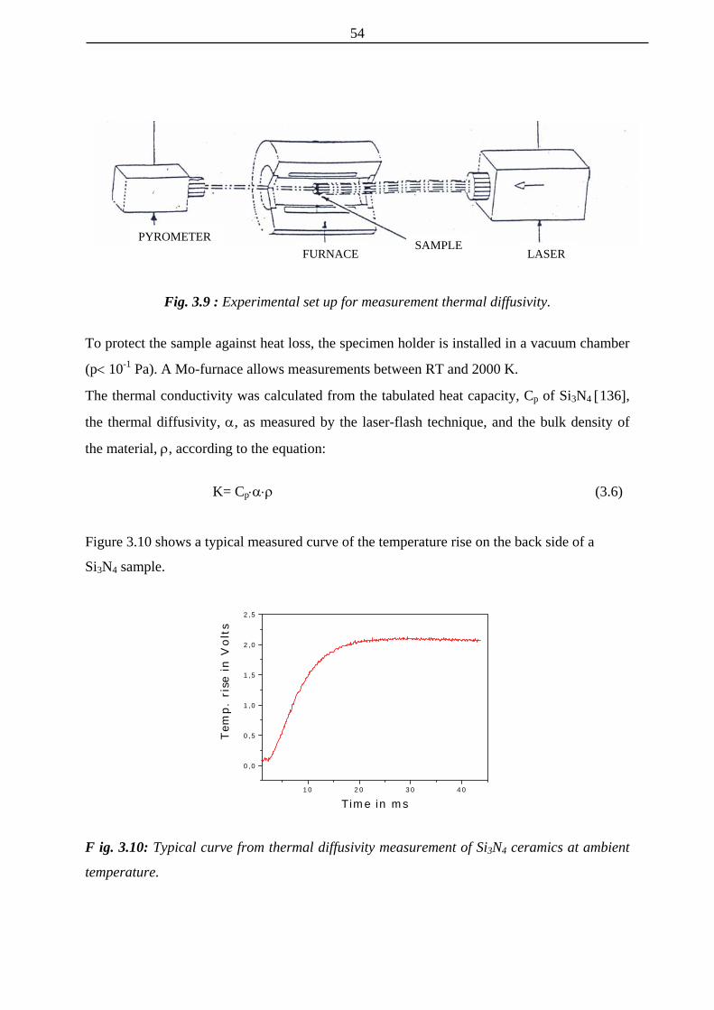
54
PYROMETER SAMPLE
LASER FURNACE
Fig. 3.9 : Experimental set up for measurement thermal diffusivity.
To protect the sample against heat loss, the specimen holder is installed in a vacuum chamber
(p< 10-1 Pa). A Mo-furnace allows measurements between RT and 2000 K.
The thermal conductivity was calculated from the tabulated heat capacity, Cp of Si3N4 [136],
the thermal diffusivity, α, as measured by the laser-flash technique, and the bulk density of
the material, ρ, according to the equation:
K= Cp⋅α⋅ρ (3.6)
Figure 3.10 shows a typical measured curve of the temperature rise on the back side of a
Si3N4 sample.
1 0 2 0 3 0 4 0
0 ,0
0 ,5
1 ,0
1 ,5
2 ,0
2 ,5
Tem
p. r
ise
in V
olt
s
T im e in m s
F ig. 3.10: Typical curve from thermal diffusivity measurement of Si3N4 ceramics at ambient
temperature.

55
4 POWDER PROCESSING
The introduction of sintering additives is a critical step in the production process.
Inhomogeneities introduced at any stage before sintering remain inside the material and
degrade the mechanical properties and reliability of Si3N4 based ceramics. Therefore, in order
to produce materials with optimum properties it is important to find powder processing routes
able to produce high homogeneity in powder premixes/mixtures.
Various preparation routes for engineering ceramics powders have been used. The best results
are obtained by chemical routes, but this method is more costly in terms of industrial
manufacturing than conventional milling techniques [137]. Milling is the most common and
industrially preferred method of adding and mixing the additives with the matrix [138].
This chapter deals with an investigation of the effects of different types of homogenization
procedures (ball milling, attrition milling and vibratory milling) on the properties of Si3N4
powder and sintered bodies.
Powders with favorable pressing and sintering characteristics are distinguished by a high
percentage of the α-Si3N4 phase (>90%), high surface area, narrow particle size range, low
content of impurities (Fe, C, Al, Ca, O) and equiaxed grain morphology [11]. In contrast, as-
received Silzot HQ is a coarse grained powder with a broad particle size distribution (chapter
3., Fig. 3.2 depicts the powder morphology). Equiaxed, rod-like and even needle-shaped
particles can be clearly identified. The presence of these particles leads to a decreasing
compactibility and hence to low green density. Therefore, the as-received Si3N4 powder could
be pressed to only about 50% of the theoretical density. This powder morphology is connected with a low specific surface area and with low oxygen
content (chapter 3, Table III-1).
According to the above mentioned criteria, raw Silzot HQ powder is not considered to be a
well sinterable powder. During the homogenization by milling several processes are occurring
simultaneously. The surface of the powder increases owing to the deglomeration and to the
grinding of the crystallites. As a result, the oxygen content increases [139].
Table IV-I shows the effects of milling time and method of dispersion on the characteristics of
the Si3N4 powder. The specific surface area increases for all types of homogenization, but it is
most pronounced in attrition milled mixtures (Fig. 4.1).

56
Table IV-I : Effects of milling time and different types of homogenization procedures on the properties of Si3N4 mixtures.
Homogenizatin Time (h)
Specific surface area (m2/g)
Content of Oxygen (wt%)
Increase of oxygen content
(wt%) Ball milling 1 5.46 2.82 1.01 Ball milling 2 5.61 2.87 1.06 Ball milling 4 6.35 3.31 1.50
Attrition milling 1 6.83 2.73 0.92 Attrition milling 2 8.99 2.89 1.08 Attrition milling 4 13.78 3.67 1.86
Vibratory milling (dry) 4 4.71 2.36 0.55 Vibratory milling (alcohol) 4 12.26 3.98 2.17
1 2 3 4
4
6
8
10
12
14
Spe
cific
sur
face
are
a (m
2 /g)
Time (h)
Fig. 4.1 : The effects of milling time on the specific surface area ( - ball milling; µ -
attrition milling; σ - dry vibratory milling; τ - alcohol vibratory milling).
For planetary-milled mixtures, the specific surface area was significantly increased after the
first hour of milling, while upon prolonged milling it stays nearly constant. In the case of
attrition-milled powders, the surface area continues to grow during prolonged milling and
increases by more than 10 m2/g after 4 h of processing, as compared with the as-received
Si3N4 powder. Vibratory milling in alcohol shows very good results, but for dry vibratory
milling the increase in specific surface area is less than for all other processing methods.
The increase in specific surface area is due to grinding of the crystallites. Fig. 4.2 illustrates
the change in particle morphology after attrition milling in comparison with as-received

57
powder. Rod-like and needle-shaped particles disappear, and all particles have an equi-axed
shape. This has positive effects on powder compaction.
(a)
(b)
Fig. 4.2 : SEM photomicrographs of as-received Si3N4 (a) and a powder attrition
milled for 4 h (b).
Table IV-I shows that during all milling procedures the oxygen content increased significantly
with milling time. This is very important because for a given additive system the amount and
the composition of the melt depend on the oxygen content in the Si3N4 powder. Higher
oxygen contents result in an increased amount of liquid phase and thus in an enhancement of
the particle rearrangement and the diffusion processes. For the coarser-grained powders this
effect is more significant. An oxygen content of at least 1.5% is necessary for high
densification [11]. Fig. 4.3 shows the oxygen content as a function of the presence of the
sintering additive and the milling procedure used. The overall oxygen content was calculated
as the sum of oxygen from the sintering additive (5 wt % LiYO2) and the oxide layer on the
surface of the Si3N4 powder. The highest increase was obtained for attrition milling (4 h) and

58
vibratory milling (4 h in alcohol), which corresponds well with the increase specific surface
area.
0,0
0,5
1,0
1,5
2,0
2,5
3,0
3,5
4,0w
d
4
21
4
21
Oxy
gen
Con
tent
(w
t. %
)
As-received Oxide Planetary Attrition Vibratory added milling milling milling
Fig. 4.3 : Oxygen content during processing with LiYO2 additives (milled for 1,2,4 h ; d-dry
milling; w-wet milling).
Fig. 4.4 shows the atomic number contrast mapping in different green compacts. The light
spots represent the Y in LiYO2 that is distributed in the green compacts. Large spots imply an
agglomeration of the additive. The number of large spots was apparently greater in the
samples prepared by planetary milling, a especially for the samples milled for 1 or 2 h.
Therefore, many agglomerates of the oxide additive exist in these compacts. The distribution
of additives is obviously more homogenous in the compacts prepared by attrition milling than
in the compacts prepared by planetary milling.
A confirmation for the higher quality of the additive distribution is the density that is achieved
after sintering (Table IV-II).
Table IV-II : Densities after sintering at 1600°C with 5% of LiYO2 additive, (TD-theoretical density).
Ball milling Attrition milling Vibratory milling* Time (hrs) Density
(g/cm3) TD (%) Density (g/cm3) TD (%) Density
(g/cm3) TD (%)
1 2,35 73,3 2,58 80,5 2 2,57 80,2 2,68 83,6 4 2,56 79,9 2,92 91,1 2,94 91,6
* wet milling

59
Ball milling Attrition milling
1 1
Fig. 4.4. (a) : Backscattered electron images of green compacts showing the Y distribution
(LiYO2 containing Si3N4 mixtures prepared by ball and attrition milling for 1h).
2 2
Ball milling Attrition milling 4 4
Fig. 4.4. (b) : Backscattered electron images of green compacts showing the Y distribution
(LiYO2 containing Si3N4 mixtures prepared by ball and attrition milling for 2 and 4 h). The
light spots represent the additive that is distributed in the green compacts.

60
The sintered density after one hour of attrition milling is as high as after 2 and 4 h of planetary
milling. With prolonged milling time attrition-milled samples increase in their density. After 4
hours of milling, a sintered density of 91% of the theoretical density is achieved. Comparable
results are obtained for vibratory milled powders (wet milling). However, during vibratory
milling, the powder mixture was contaminated by wear debris from the milling vial (tungsten
carbide).
Different microstructures of sintered bodies are obtained for different homogenization
methods (attrition and vibratory milling). The material produced from attrition-milled
mixtures has a finer-grained microstructure with lower aspect ratios compared to the
vibratory-milled mixtures (Fig. 4.5). In spite of the higher aspect ratio of the silicon nitride
(a)
(b)
Fig. 4.5 : SEM micrographs of polished and plasma etched sections of the sintered samples
made by different homogenization procedures (a-attrition milling and b-vibratory milling).

61
grains of vibratory-milled mixtures, the presence of WC deteriorates the high-temperature
strength due to its thermal decomposition and the oxidation of tungsten.
In conclusion, using three different mechanical mixing processes (attrition milling, ball
milling and vibratory milling) for the introduction of additives (LiYO2) in Si3N4 powder, the
best results are obtained for attrition milling. This method yields a good dispersion of the
additive powder in fine unagglomerated Si3N4 without contamination. It also yields good
sintering characteristics.
Vibratory milling leads to a good dispersion of the additive, but the mixture is contaminated
by WC wear debris which remains inside the materials during and after sintering and may
affect the properties of the ceramics.

62
5 DENSIFICATION
5.1 Dilatometric study
The densification behavior of Si3N4-based ceramics by pressureless sintering is affected
directly by the characteristics of the liquid phases present. Densification is negligible before
the formation of the liquid and can be improved by lowering the eutectic temperature and
viscosity of the liquid phase. Hence, it is very important to find the minimum liquid-forming
temperature, i. e. the effective densification temperature. However, identifying the liquid
forming regions for powder compacts of the systems Si3N4-additive is quite complicated due
to the presence of variable amounts of SiO2, which is an inherent component of Si3N4
powders. In order to optimize the Si3N4-additive material system, a series of dilatometric tests
was performed.
5.1.1 Densification temperature
According to the ternary diagrams for the Li2O-Y2O3-SiO2 [140] and Li2O-Al2O3-SiO2 [141],
systems, the nominal eutectic temperature is 1350°C in both cases. However, due to the
dissolution of Si3N4 into the liquid phase, the overall liquid forming temperature is expected
to be lower than the nominal eutectic temperature.
5.1.1.1 Si3N4-LiYO2-SiO2 system
The dilatometric data (Fig. 5.1) show that shrinkage first occurs at 1200°C and becomes rapid
at 1275°C in the case of samples with 15 and 20 wt% of LiYO2 additive. In case of samples
with lower additive contents (5 and 10 wt%) the onset of shrinkage is retarded and its
magnitude is much reduced. The onset of shrinkage can be related to liquid formation in the
samples. This is in response to the melting point in the Li2O-SiO2 system (1255°C) [142]. The
shrinkage accelerates when enough liquid phase for efficient densification by particle
rearrangement has been formed.
Fig. 5.2. shows the effect of additive content on the linear shrinkage of the samples after
heating to 1500°C in dilatometer experiments. More liquid is formed as the amount of
additive is increased. The maximum linear shrinkage of 11.9 % is obtained for 20 wt% of
additive.

63
Fig. 5.1: Length change of Si3N4 green bodies (A-5 wt%, B-10 wt%, C-15 wt%, D-20 wt% of LiYO2) between room temperature and 1500°C. A cylinder-shaped test body was examined by dilatometry in nitrogen atmosphere.
0 100 200 300 400 500
-1000
-500
0
500
1000
1500
-20 wt %
-15 wt %
-10 wt %
-5 wt %
D
C
B
ATem
pera
ture
(o C
)S
hrin
kage
(10
-6m
)
Time (min)
5 10 152
4
6
8
10
12
20
Shr
inka
ge (
%)
Additive content (wt%)
Fig. 5.2: Linear shrinkage versus additive content in dilatometer experiments, after a holding time of 5 min at 1500°C.

64
The presence of Li2O in the liquid leads to lower melting point and a less viscous liquid phase
at a given temperature, which allows faster transport of material through the melt. The
redistribution of the liquid and the filling of pores is also facilitated. This allows high density
values to be reached at relatively low temperatures (Fig. 5.3). The density of samples with 15
wt% of additive is 2.84 g/cm3 at 1300°C and more than 2.95 g/cm3 at 1350°C. With
prolonged heating time, differences in the degree of densification become smaller. The
increment in the sintered density likewise diminishes with increased quantity of additives
(Fig. 5.4).
1300 1350 1400 1450 15002.82
2.98
2.96
2.94
2.92
2.90
2.86
2.88
2.84Bul
k de
nsity
(g/
cm3 )
Temperature (oC)
Fig. 5.3. Density according to dilatometric measurements of Si3N4 with 15 wt% of LiYO2
additive after a holding time of 5 min at the temperatures indicated. The densification of Si3N4 ceramics is enhanced by increasing the liquid content and
decreasing the liquid viscosity. The higher the LiYO2 additive content in the liquid, the higher
the oxygen content and therefore the lower the viscosity of liquid phase. On the other hand,
dissolution of some Si3N4 into the liquid increases the viscosity of silicon-oxynitride glasses
due to increasing nitrogen content. This also influences the shrinkage rate during densification
(Fig. 5.5).
The results show that all materials were not fully dense after dilatometric measurements up to
1500°C. The best results were obtained for samples with 15 or 20 wt% of additive (Fig. 5.4).

65
In view of the materials’ properties that can be expected, 15 wt% additive content may be
considered as an auspicious compromise.
5 10 15 20
3.2
3.0
2.8
2.6
2.4
2.2
2.0
1.8
1.6
Bul
k de
nsity
(g/
cm3 )
Additive content (%)
Fig. 5.4: Influence of the amount of LiYO2 on the densification of Si3N4 samples fired at
1500°C with a holding a time of 5 min.
The change in length and rate of shrinkage are shown in Fig. 5.5 (a) and (b) respectively. It
can be seen that the shrinkage curve has a sigmoidal shape. As mentioned earlier, shrinkage
starts at about 1200°C and proceeds rapidly above 1275°C. The shrinkage continues during
the first 30 min of isothermal annealing at 1500°C, after which a plateau is reached. The total
linear shrinkage is about 11% immediately after reaching 1500°C and 12.5% after annealing
for 2 h at this temperature.
The shrinkage velocity curve shows three maxima at 1275°C, 1364°C and 1453°C (points 2 to
4). The appearance of the liquid in the sample starts at 1180°C (point 1). Point 1 agrees with
the melting temperature in the Li2O-SiO2 system [142]. The maximum at 1275°C (point 2) is
related to an increasing amount of liquid phase, which surrounds the silicon nitride particles
completely, favoring grain rearrangement [143]. The XRD pattern of the sample quenched at
this temperature shows crystalline yttrium-silicon oxynitride Y5(SiO4)3N (“N−apatite”) and
lithium-silicon oxynitride (LiSiNO) phases, which indicates the dissolution of some Si3N4

66
0
200
400
600
800
1000
1200
1400
1600
(a)
4321T
empe
ratu
re (
o C)
-400
-300
-200
-100
0
Shr
inka
ge (
10-6
m)
Fig. 5.5 : Shrinkage (a) and shrinkage velocity (b) of a silicon nitride green body with 15%
LiYO2 additive showing characteristic features at (1) 1180°C; (2) 1275°C; (3) 1364°C and
(4) 1453°C.
150 200 250 300 350 400
0
200
400
600
800
1000
1200
1400
1600 4321
Time (min)(b)
Tem
pera
ture
(o C
)
-8
-6
-4
-2
0
2
4
Shr
inka
ge v
eloc
ity (
10-6
m/m
in)
into the liquid (Table 5-I). This confirms that LiYO2 acts as a very good flux and a solvent for
Si3N4 which is also a prerequisite for a good sintering additive [144].

67
The XRD pattern of the sample quenched at 1364°C (point 3) shows the disappearance of the
LiSiNO phase resulting in an increasing amount of the liquid phase and consequently, an
accelerated shrinkage. The maximum at 1453°C corresponds to the onset of the phase
transformation from α−Si3N4 to β−Si3N4. The densification rate decreases from this point,
coinciding with a significant degree of α→β transformation.
Table 5-I : Phase contents of the samples quenched at different temperatures.
Temperature (°C) Phase Content (wt %) Remarks
1180 β-Si3N4 21 % onset of shrinkage
1275 β-Si3N4 22 % LiSiNO, Y5(SiO4)3N
1st maximum of shrinkage velocity
1364 β-Si3N4 23 % Y5(SiO4)3N
2nd maximum of shrinkage velocity
1453 β Si3N4 26 % Y5(SiO4)3N
3rd maximum of shrinkage velocity
1500 β-Si3N4 32 % Y5(SiO4)3N after annealing for 5 min
1500 β-Si3N4 65 % Y5(SiO4)3N after annealing for 2 h
5.1.1.2. Si3N4-Li2O-Al2O3-SiO2 system
The dilatometric data (Fig. 5.6) show that shrinkage first occurs at 1080°C and increases
somewhat at 1270°C for all samples, except for thet with 5 wt% of additive. The shrinkage
continues during the isothermal annealing at 1500°C. The onset of shrinkage is related to
liquid formation in the sample compacts.
The effect of additive content on the linear shrinkage of the samples is shown in Fig. 5.7.
Linear shrinkage increases significantly from 3 to 8% for the samples containing 5 and 10%
of additives respectively. However, with further increasing additive content, linear shrinkage
remains nearly constant. Linear shrinkage values ranging from 8.1 to 8.5% are obtained for
samples containg 10, 15 and 20 wt% of additives.
The remarkably low shrinkage of samples with 5 wt% of additive could be attributed to an
insufficient liquid formation. In general, more liquid is formed when the amount of additive is
increased. In spite of growing additive content, it is found that the shrinkage reaches nearly
the same value in the range of 10 to 20 wt% of additives. This indicates that the liquid volume

68
does not differ much with increasing additive content or the liquid content has not much
pronounced influence on densification.
100 200 300 400 500
-1000
-500
0
500
1000
1500
C-15%B-10%
D-20%
A-5%
Tem
pera
ture
(o C
)S
hrin
ange
(10
-6m
)
Time (min)Fig. 5.6 : Length change of Si3N4 green bodies (A-5 wt%, B-10 wt%, C-15 wt%, D-20 wt% of
LiAlSiO4 between room temperature and 1500°C. A cylinder-shaped test body was examined
by dilatometry in nitrogen atmosphere.
5 10 15 20
2
4
6
8
Shr
inka
ge (
%)
Additive content (%)Fig. 5.7: Linear shrinkage versus LiAlSiO4 additive content in dilatometer experiments, after
a holding time of 5 min at 1500°C.

69
The maximum achieved density i.e. 2.65 g/cm3 is obtained for 10 wt% of additive. Actually,
the presence of Li2O allows for the formation of a liquid phase at very low temperature. In
case of samples with 10 wt% of additive the density has already increased to 2.03 g/cm3 at
1080°C, that is nearly 10 % higher than the density of the starting mixture. With prolonged
heating time, the densitity further increases to 2.65 g/cm3 at 1500°C (Fig. 5.8). In spite of the
low sintering temperatures all the materials were not fully dense after dilatometric
measurements up to 1500°C. This has to be attributed to the the influence of the furnace
atmosphere inside the dilatometer and the small size of the samples.
The influence of the amount of LiAlSiO4 additive on the densification of Si3N4 is shown in
Fig. 5.9. The best results were obtained for bodies with 10 or 15 % of additive, with atending
of decreasing density upon further increase of the additive content.
1000 1100 1200 1300 1400 1500
2.7
2.5
2.1
2.2
2.3
2.4
2.6
2.0
Bul
k de
nsity
(g/
cm3 )
Temperature (oC)Fig. 5.8 : Density according to dilatometric measurements of Si3N4 with 10 wt% of LiAlSiO4
additive after a holding time of 5 min.
The shrinkage and shrinkage rate during densification of a sample with 10 % of additive are
shown in Fig. 5.10. The shrinkage rate curve shows three maxima at 1180°C, 1275°C and
1490°C indicated by three points 2 to 4.

70
The XRD patterns of the samples quenched at these temperatures show different phase
compositions as listed in Table 5-II, indicating that the viscosity and volume of the liquid
phase change significantly during heating.
5 10 15 202,0
2,2
2,4
2,6
2,8
Bul
k de
nsity
(g/
cm2 )
Additive content (%)
Fig. 5.9: Influence of the amount of LiAlSiO4 additive on the densification of Si3N4 samples
fired at 1500°C with a holding a time of 5 min.
The appearance of the liquid in the sample starts at 1080°C (point 1) corresponding to the
eutectic melting point in the Li2O-SiO2 phase diagram [142]. The maximum at 1180°C (point
2) is related to an increasing amount of the liquid phase. Its phase composition shows
lowering of the intensity of β-eucryptite i.e. LiAlSiO4 phase due to its melting. The presence
of coesite (SiO2) is associated with excess silica which has crystallized from the liquid during
cooling. The XRD pattern for the sample quenched at 1275°C (point 3), shows the
disappearance of the β-eucryptite phase but appearance of β-spodumen (LiAlSiO6) which is a
phase with the same cation ratio (Li : Al) as a LiAlSiO4 but containing a higher amount of
silica. In spite of the total conversion of LiAlSiO4 additive into liquid phase the total amount
of liquid phase does not increases significantly due to partial crystallization in to a new phase
(LiAlSiO6). This leads only to moderate increase of density.

71
The maximum at 1490°C, which occurs together with a decrease in the XRD intensity of the
LiAlSiO6 phase and an increase in the intensity of SiO2, corresponds to a increasing volume
of the liquid phase.
0 100 200 300 400 500
0
200
400
600
800
1000
1200
1400
1600
Time (min)
Tem
pera
ture
(o C
)
-8
-6
-4
-2
0
(a)
Shr
inka
ge (
%)
Fig. 5.10 : Shrinkage (a) and shrinkage velocity (b) of a silicon nitride green body with 15% LiAlSiO4 additive showing characteristic features at (1) 1080°C, (2) 1180°C; (3) 1275°C and
0 100 200 300 400 5000
250
500
750
1000
1250
1500
Time (min)
Tem
pera
ture
o C
-12
-10
-8
-6
-4
-2
0
2
(b)
4321
Vel
ocity
(m
m/m
in)
(4) 1490°C.

72
However, the α/β-Si3N4 ratio remains the same up to 1500°C indicating that no significant
transformation takes place during the first stage of sintering. This means that the initial stage
is related with the formation of the liquid phase and to the reaction between the sintering
additive and the surface silica from Si3N4 grains.
Table 5-II : Phase contents of the samples quenched from different temperatures.
Temperature (° C) Phase content (wt%)
Remarks
1080 β-Si3N4 20 % β-LiAlSiO4
onset of shrinkage
1180 β-Si3N4 20 % β-LiAlSiO4, SiO2
1st maximum of shrinkage velocity
1275 β-Si3N4 20 % β-LiAlSi2O6, SiO2
2nd maximum of shrinkage velocity
1490 β Si3N4 20 % β-LiAlSi2O6, SiO2
3rd maximum of shrinkage velocity
1500 β Si3N4 20 % β-LiAlSi2O6, SiO2
after annealing for 5 min
1500 β-Si3N4 35 % SiO2
after annealing for 2 h
The results from the dilatometric measurements show that materials with both additive
systems were not fully dense after heating up to 1500°C. Densification is more effective with
the LiYO2 system than with the LiAlSiO4 system under the same sintering conditions as
shown in Fig. 5.4 and Fig. 5.9. This behavior can not be explained exclusively by the
difference in the volume fraction and liquid viscosity of the two systems. Reaction with the
reducing gas atmosphere inside the graphite-heated sintering furnace should also be taken into
consideration [145].
It was found that the crystallization of the secondary phases from the melt can already occur
during sintering especially for compositions on a tie line between one secondary phase and
Si3N4. In this case, the volume fraction of the liquid phase is strongly reduced and complete
densification is impossible [146]. According to the XRD patterns and densities of the samples
quenched at particular temperatures during dilatometric measurement, the amount of liquid
due to the sequence of chemical reactions increases only slowly with temperature. Hence, the
densification may be assumed to take place with less particle rearrangement than is usual in
the liquid phase sintering. This explains why the variation in shrinkage and density that is
obtained for samples having different additive contents is much smaller than in case of the
LiYO2 additive.

73
In the case of the LiYO2 system, the density increases monotonically with increasing additive
content according to Fig. 5.4. Higher additive content provides a higher volume of liquid
needed to fill the porosity. In addition, an appreciable amount of Si3N4 can be dissolved in the
liquid formed, which additionally leads to higher densification [56].
5.2 Sintering density
Nonisothermal sintering experiments up to 1500°C show that the relative densities reached
are still too low for high mechanical strength and hardness. In order to further increase the
density to above 95%, densification was conducted at different temperatures from 1550°C to
1700°C with 50 K intervals for different holding times.
The influence of temperature on densification during sintering at higher temperatures for very
short annealing time (5 min) is given in Fig. 5.11. At lower temperatures densification is more
1550 1600 1650 1700
86
88
90
92
94
96
Rel
ativ
e de
nsity
(%
)
Temperature (oC)
LiYO2 LAS
Fig. 5.11 : The difference in the densification behavior between Si3N4-LiYO2 and Si3N4-
LiAlSiO4 ceramics with 15% of additive sintered at different temperatures from 1500°C up to
1700°C with a holding time of 5 min.
pronounced for bodies sintered with LiYO2 additive. The densification increases
monotonically with increasing temperature. In the case of LiAlSiO4 additive, with increasing

74
temperature the increment between the density values gets higher until 1650°C. At 1700°C, >
95% of the theoretical density are obtained with both additive systems.
The densification behavior at 1500°C as a function of annealing time is shown for the Si3N4-
LiYO2 and Si3N4-LiAlSiO4 systems in Fig. 5.12 and Fig. 5.13, respectively.
0 60 120 180 240 300 360 420 480
86
88
90
92
94
96
98
100
5% 10% 15% 20%R
elat
ive
dens
ity (
%)
Time (min)Fig. 5.12 : Relative densities at 1500°C vs. annealing time for Si3N4 with LiYO2 additives (5,
10, 15 and 20%).
At 1500°C, densification is higher by nearly 2% with the LiYO2 additive when compared to
LiASiO4. In the case of LiYO2, the maximum density is obtained for bodies having higher
additive content, while in the case of LiAlSiO4 additive, the densification is nearly the same
for bodies with 10 and 15% of additives. The difference in densification versus additive
content is more pronounced in the LiYO2 additive system.
The relationships between relative density and sintering temperature for the compositions
with different amounts of additives are listed in Table 5-III and Table 5-IV, respectively.
In case of bodies with at least 15 wt% of LiYO2 additive, high relative densities are obtained
after just 2 h of sintering, while the densities remain nearly constant upon prolonged sintering.
However, all samples sintered at higher temperature and longer annealing times show the
same trend of decreasing density. The samples sintered at 1550°C were found to exhibit
higher densities in comparison with samples sintered at 1600°C and 1650°C.

75
0 60 120 180 240 300 360 420 480
80
85
90
95
100
5% 10% 15% 20%R
elat
ive
dens
ity (
%)
Time (min)Fig. 5.13 : Relative densities at 1500°C vs. anealing time for Si3N4 with LiAlSiO4 additives (5,
10, 15 and 20%).
Higher relative density obtained at lower sintering temperatures may be attributed to the lower
partial pressure of evaporating phases at these lower temperatures, especially with respect to
lithia and silica. It has been noticed during dilatometric measurement that a significant mass
Tabele 5-III : Densities after sintering with different amounts of the LiYO2 additive.
1550°C 1600°C 1650°C Additive
content (wt%)
2 h 4 h 8 h 2 h 4 h 8 h 2 h 4 h 8 h
5 88.7 88.95 88.1 88.5 88.2 87.8 88.1 80.0 79.6
10 94.9 95.1 95.0 95.2 94.9 94.2 93.7 93.1 92.4
15 98.3 98.3 98.3 98.3 98.1 97.2 98.3 97.8 97.5
20 98.3 98.2 98.3 98.3 97.8 97.8 98.2 97.6 97.5
loss occurred. As shown in Fig. 14, Li2O starts to evaporate from the samples at temperatures
above 1300°C and the Li concentration is drastically reduced after holding times of several
hours at 1500°C. After 8 h, the residual Li2O content is as small as 0.08 wt%. This is in good
agreement with published data [147] for the vapor pressure of Li2O and its evaporation at
higher temperatures. In contrast, Y2O3 is very stable based on thermodynamic calculations

76
[148] and has no tendency for volatilization under the conditions investigated. Therefore, it
can be concluded that Li2O is removed in gaseous form during sintering, changing the liquid
to a comparatively high-melting, Y2O3-rich composition. The lowest melting temperature in
the system Y2O3-SiO2 is 1650°C [98]. Thus the liquid phase is mostly transient and this must
have a marked influence on the kinetics of densification and phase transformations in the
system studied.
84 60 2
1.6
1.4
1.2
1.0
0.8
0.6
0.4
0.2
150014001300
Li2O
con
tent
(w
t%)
Temperature (oC) Time (h)
Fig. 5. 14: Lithia losses of Si3N4 compacts with 15 wt% of LiYO2 additive during dilatometric
measurement and upon prolonged annealing time at 1500°C.
In case of LiAlSiO4 additive, the samples sintered with lower additive content exhibit higher
densities in comparison with samples containing more additive. The highest value of 98.3%
for the density is obtained for bodies with 10% additive content. The densities remain nearly
constant on prolonged sintering at all sintering temperatures.

77
Table 5-IV : Densities after sintering with different amounts of the LiAlSiO4 additive.
1550°C 1600°C 1650°C Additive
content (wt%)
2 h 4 h 8 h 2 h 4 h 8 h 2 h 4 h 8 h
5 90.1 89.7 89.4 89.5 89.2 89.0 89.1 88.8 87.9
10 98.3 98.3 98.3 98.3 98.1 98.1 98.1 97.7 97.5
15 98.3 98.3 98.1 98.3 97.9 97.2 97.4 97.2 96.8
20 93.6 92.7 92.4 93.0 92.3 92.0 92.3 91.5 91.2
According to XRD patterns (Table 5-II), at 1500°C all of the LiAlSiO4 additive is converted
into liquid. The liquid phase formed in the LiYO2 additive system contains less silica and
hence, it is thermodynamically more stable than the liquid phase in the LiAlSiO4 system
which contains a substantial amount of silica. In other words, a larger amount of the liquid
phase in the LiAlSiO4 system leads to more evaporation according to the reaction:
Si3N4 (s) + 3 SiO2 (l) = 6 SiO (g) + 2 N2 (g) (5.1)
1550 1600 1650 1700
1
2
3
4
5
6
7
8
9
10
LY 5% LAS 10% LY 10% LAS 15% LY 15% LAS 20% LY 20%
Mas
s lo
ss (
%)
Temperature (oC)
Fig. 5.15 : Mass loss as a function of temperature for Si3N4 compacts with different amounts
of LiYO2 and LiAlSiO4 additives during sintering with a holding time of 5 min.

78
High mass loss is harmful to sintering, which is reflected in the observation that the density of
samples having 20 % of additive is always smaller than densities of bodies with 10 and 15 %
of additive.
The mass loss upon sintering with the LiAlSiO4 additive system in comparison to the LiYO2
system is shown in Fig. 5.15. The same trend is also observed during isothermal annealing
(Fig.5.16 a,b).
0 100 200 300 400 500
1
2
3
4
5
6
7
8
9
5 LY 10 LY 15 LY 20 LY
10 LAS 15 LAS 20 LAS
1550oC
Mas
s lo
ss (
%)
Time (min)
60 120 180 240 300 360 420 480 5400
2
4
6
8
10
12
1600oC 5 LY 10 LY 15 LY 20 LY
15 LAS 10 LAS 20 LAS
Mas
s lo
ss (
%)
Time (min)
Fig. 5.16 : Mass loss of Si3N4 ceramics with the additive systems LiYO2 (LY) and LiAlSiO4 (LAS), heat-treated at 1550°C (a) and 1600°C (b) under 0.1 MPa N2 as a function of soaking time.

79
Reactions between Si3N4 and the glassy phases are responsible for the instability of Si3N4
ceramics at elevated temperature. However, Al2O3 and Y2O3 are stable based on
thermodynamic calculations [148]. In contrast, the high vapor pressure of lithia causes its easy
evaporation as mentioned earlier. It is expected on the basis of the vapor pressure data for
Li2O [147] that lithia should volatilize completely at higher temperatures. However, the
results of the chemical analysis of the samples are in contradiction with this assumption,
especially for LiAlSiO4.
The content of lithium in the Si3N4 ceramics sintered for 4 h at various temperatures, is
indicated in Fig. 5.17. The lithium content in the samples changes slightly in the case of the
LiAlSiO4 additive. However, with the LiYO2 additive the lithium content decreases
1550 1600 1650 17000,1
0,2
0,3
0,4
0,5
0,6
0,7
0,8
Li2O
con
tent
(w
t%)
Temperature (oC)
LiYO2 LiAlSiO4
Fig.5.17 : Mass loss of lithium in Si3N4 samples sintered at various temperatures.
significantly with temperature. On the basis of these findings, it can be concluded that the
major part of the mass loss of the Si3N4 ceramics during sintering occurs according to the
reaction (5.1), as mentioned before. This reaction is well known from thermodynamical and
experimental work on the Si-N-O system [149, 150]. Since the silica content in the liquid
phase is higher with the LiAlSiO4 additive than with the LiYO2 additive, the rate of the
decomposition reaction (5.1) is faster and consequently the mass loss is high for samples
having 20 % of additives. Additionally for higher additive amounts, gas bubbling occurs

80
caused by an increased formation of gaseous SiO [101]. This is the case with the LiAlSiO4
additive which has a higher oxygen content than the LiYO2 additive.
5.3 General remarks
The three controlling stages: particle rearrangement, solution-precipitation and grain growth
are observed in many Si3N4 systems [2]. The densification is controlled by particle
rearrangement and by solution-diffusion-reprecipitation processes. Particle rearrangement
contributes to densification at lower temperatures and solution-diffusion-reprecipitation is
dominant at higher temperatures. For the LiYO2 system, the densification depends largely on
the sintering additive content. The larger amount of additive means a higher volume of liquid
phase, which is favorable for efficient particle rearrangement resulting in the higher value of
density. In case of the LiAlSiO4 additive, it is found that the densification is less dependent on
the additive content. Up to 1500°C, densification is not accompanied by α→β Si3N4
transformation. Thus, the final density is thought to be reached largely without the
intervention of the dissolution-diffusion-reprecipitation mechanism. This means that the
overall sintering kinetics at low temperatures is less retarded when using the LiYO2 additive
in comparison to the LiAlSiO4 additive, resulting in higher densities obtained at lower
temperatures and short annealing times. With prolongated heating time, the differences in the
degree of densification become smaller. It needs to be pointed out that the transport kinetics
are also decisive for the phenomena of phase transformation (see chapter 6) and
microstructural development (chapter 7).

81
6 PHASE TRANSFORMATION
The α→β phase transformation is a phenomenon which always occurs when α-Si3N4
containing powders will be liquid phase sintered [151]. This process is substantially
influenced not only by the amount but also by the chemistry of the liquid phase. It occurs by
solution-diffusion-reprecipitation. Hence it is of great significance to describe this
mechanism, which in turn has an impact on grain growth and microstructural development. In
this chapter the various factors influencing the transformation, its kinetic and the relation of
phase transformation to densification are dealt with.
6. 1 Temperature and time dependence Fig. 6.1 shows the changes in β-Si3N4 phase content as a function of sintering temperature.
With both additive systems, the time dependence of the α→β phase transformation displays a
sigmoidal behaviour. However, the starting temperatures of the phase-transformation are
significantly different for the two systems. With the LiYO2 additive, the phase transformation
1200 1300 1400 1500 1600 1700
20
40
60
80
100 LiYO2 LiAlSiO4
Beta
Pha
se (%
)
Temperature (oC) Fig. 6.1 : The α→β-Si3N4 phase transformation as a function of temperature in the Si3N4-
LiYO2 and Si3N4-LiAlSiO4 systems for 5 minutes of annealing.

82
already commences at 1300°C although only a small amount of transformation is observed.
For samples with 15 wt% of additives, the transformation accelerates at 1500°C and is
terminated at 1700°C after 5 minutes of annealing time.
In the case of the LiAlSiO4 additive system the transformation starts at 1500°C and increases
only slightly with temperature (Fig. 6.1). The crystalline lithium aluminum silicate phase β-
spodumene (LiAlSiO6) remains stable as long as the temperature is lower than 1500°C. In this
stage, the liquid content is limited in the system. The β-spodumene phase, however, starts to
dissolve into the liquid as the temperature exceeds 1500°C. This increases the amount of
liquid. The maximum degree of α→β-Si3N4 transformation for samples with 15 wt% of
additive was about 45% at 1700°C after 5 minutes of sintering time.
However, with prolongated annealing time the degree of phase transformation significantly
increases in both cases (Fig. 6.2). With the LiYO2 additive the phase transformation is
finished at 1500°C after 1 hour of sintering, while a higher temperature of 1600°C is
necessary to convert all α-Si3N4 phase in the LiAlSiO4-containing system. The delayed phase
transformation in the
1500 1550 1600 165020
30
40
50
60
70
80
90
100
LiYO2 LiAlSiO4
β-S
i 3N4
(%)
Temperature (oC) Fig. 6.2 : The phase transformation as a function of temperature in the Si3N4-LiYO2 and the
Si3N4-LiAlSiO4 systems (15 wt%) for 1 hour of annealing.

83
LiAlSiO4-containing system suggests that phase transformation is sensitive to the liquid
viscosity.
6. 2 Influence of additive content
The sintering experiments showed that the densification process is accompanied by the α→β
Si3N4 phase transformation with LiYO2 at low temperatures (below 1500°C), while the action
of the dissolution-diffusion-reprecipitation mechanism is retarded with the LiAlSiO4 additive
at the same temperatures. Thus the phase transformation is faster in the LiYO2-SiO2 system.
Particularly, in the Si3N4-LiYO2 system the degree of phase transformation increases with
increasing additive content. This can be explained by the fact that increasing volume fraction
of the liquid the amount of solute transported through the intergranular liquid film increases
and a larger amount of phase transformation results.
Fig. 6.3. and Fig. 6.4. show the effect of additive content on phase transformation during
sintering of Si3N4-LiAlSiO4 ceramics as a function of temperature and the annealing time,
respectively.
1500 1550 1600 1650 170030
40
50
60
70
80
90
100
w t% 5 10 15 20β-
Si 3N
4 (%
)
Tem perature oC Fig. 6.3 : The effect of additive content on α→β-Si3N4 phase transformation during the
sintering of Si3N4-LiAlSiO4 ceramics for 1 h at different temperatures.
In case of the Si3N4-LiAlSiO4 system increasing the additive content leads a decreasing
degree of phase transformation. The large additive content increases resulting in the longer

84
distance and larger difficulty for the diffusion of Si and N along the liquid phase and therefore
the phase transformation is retarded with increasing additive content.
0 60 120 180 240 300 360 420 480
20
40
60
80
100
β-S
i 3N4
Time (min)
wt% 5 10 15 20
Fig. 6.4 : The effect of additive content on α→β-Si3N4 phase transformation during the
sintering of Si3N4-LiAlSiO4 ceramics at 1500°C.
6. 3 Kinetics of phase transformation
The curves for the time dependence of the α→β transformation suggest that the conversion
kinetics is of first order. This can be described by the equation:
αα Kdtd
−= (6.1)
where K is a rate constant which accounts for the influence of temperature and α is the
concentration of the α- Si3N4 phase in the sintered samples. The transformation rate depends
not only on the concentration of the α-phase, but also on the composition and amount of
liquid phase as given by the parameter K. The volume and viscosity of the vitreous phase will
determine the extent to which compositional gradients and the nitrogen supersaturation in the

85
α-Si3N4/liquid interface are maintained. The plots of log(α) against time are linear (Fig. 6.5.
and Fig. 6.6) which supports the validity of equation (6.1).
4 6 8 10 12
1.6
1.4
1.2
1.0
wt% 10 15 20
log(α
)
Time (h)
Fig. 6.5 : Linear dependence of the logarithm of the α-Si3N4 concentration on time for Si3N4
containing various amounts of LiYO2 additive at 1450°C.
In the LiYO2 system, the transformation rate constant increases with increasing additive
content while the opposite behavior is observed in the LiAlSiO4 additive system, i.e. the rate
constant decreases with higher additive content. The addition of Y2O3 to silica produces an
important accelerating effect on both the phase transformation and the densification of Si3N4
ceramics [152]. In this case, a higher additive content creates a higher volume of liquid phase,
and as a result, faster α→β phase transformation and higher densities are obtained (chapter 5).
In the LiAlSiO4 additive system the more the liquid phase is present, the longer it will take to
reach the total α→β conversion.

86
0 60 120 180 240 300 360 420 4800,6
0,8
1,0
1,2
1,4
1,6
1,8
2,0
log(α
)
Time (min)
wt% 10 15 20
Fig.6.6 : Linear dependence of log α-phase content on time for Si3N4 containing various
amounts of the LiAlSiO4 additive at 1500°C.
6. 4 Transformation mechanism The main factor that determines the kinetics of phase transformations is the diffusion of Si
and N atoms in the liquid phase. The phase transformation is rate-controlled by interfacial
reactions if the diffusion velocity is high and by material transport if the diffusion velocity is
low. Sintering additives affect this behaviour by changing the viscosity and amount of the
liquid phase [153,154]. The rate transformation is strongly influenced by changing liquid
phase content in the case of the diffusion mechanism. In contrast, it is independent of the
liquid volume in the case of interface reaction control [155].
In this study, the phase transformation is very much affected by changing the additive content
for both systems. Thus, it can be concluded that the phase transformation with LiYO2 additive
as well as with the LiAlSiO4 additive is mainly diffusion-controlled. The difference in
transformation rate between the two additive systems can be explained by the fact that the
yttrium ion is primarily a network modifier in a Y-Si-O-N glass [156], i.e. it perturbs Si-O
bonds thus allowing rapid diffusion of ions through the liquid phase. On the other side Si has
a different behaviour, i.e. it is a glass-former and the liquid phase is more rigid compared to

87
the Y-Si-O-N glass. The nominal amount of Si in the material with LiAlSiO4 additive is much
higher than in the material with LiYO2 resulting in slower mass transport.
6. 5 Relation of transformation to densification
Densification and α→β phase transformation are two important phenomena which occur
during the sintering of Si3N4 ceramics. However, it is difficult to determine the relationship
between them. There have been reports in the literature that both occur nearly
simultaneously [157], but the existence of a lag between the two reactions has also been
observed [158].
The present study shows that the phase transformation and densification do not have a
straightforward relationship with each other. This is illustrated in Fig. 6.7 where the extent of
densification and α→β phase transformation is compared as a function of sintering
temperature.
20
40
60
80
100
1300 1400 1500 1600 1700
20
40
60
80
100
LiAlSiO4
Rel
ativ
e de
nsity
(%
)
β - phase LiYO2
β-S
i 3N4
(%)
Temperature (oC)
LiAlSiO4
Relative density LiYO2
Fig. 6.7 : Densification and phase transformation as a function of sintering temperature for
LiYO2-Si3N4 and LiAlSiO4-Si3N4 systems after a holding time of 5 min.
.
In both systems, there is a lag between densification and phase transformation showing that
the major amount of transformation occurs in a later sintering stage. At 1400°C, almost no

88
transformation is observed, while more than 90 % and 80 % of the theoretical density have
already been reached for the LiYO2 and LiAlSiO4 additives, respectively. At higher
temperatures, the differences in the degree of densification and phase transformation become
smaller in case of the LiYO2 additive, while it is at 1700°C still present in case of the
LiAlSiO4 additive.
Fig. 6.8 depicts the relationships between densification and phase transformation as a function
of sintering time for both types of materials. In both cases, the differences in the degree of
densification and phase transformation diminish with prolongated heating time. Both
processes are particularly fast in the LiYO2-Si3N4 system where the densification and phase
transformation have gone to completion after 60 minutes already.
30
40
50
60
70
80
90
100
110
60 120 180 240 300 360 420 480
30
40
50
60
70
80
90
100
110
30
40
50
60
70
80
90
100
110
30
40
50
60
70
80
90
100
110
30
40
50
60
70
80
90
100
110
LiYO2
LiAlSiO4
β-Si3N4 phase
Relative density
LiYO2
Rel
ativ
e de
nsity
(%
)
β-S
i 3N4
(%)
LiAlSiO4
Time (min)
Fig. 6.8 : The relationship between densification and phase transformation as a function of
sintering time for LiYO2-Si3N4 and LiAlSiO4-Si3N4 additive systems (with 15 wt% of additive
and at a sintering temperature of 1500°C).

89
The addition of Y2O3 to silica produces an important accelerating effect on both,
transformation and densification of Si3N4 ceramics [152]. In this case, higher additive content
creates a less viscous liquid phase resulting in faster α→β phase transformation and higher
densities obtained (chapter 5). In the LiAlSiO4 system the densification and transformation
behavior is more complicated and it needs more work to clarify the details.

90
7 MICROSTRUCTURE
The microstructure has a crucial influence on the particular properties of a final material.
Thus, the improvement of mechanical properties by microstructural control has been one of
the main topics of interest in the development of Si3N4 ceramics. [159, 160]. The amount, size
and morphology of the α- and β-Si3N4 grains are the key factors for the microstructure
development. Generally, the microstructure is characterized by the three features: Si3N4
grains, the secondary crystalline phases and the amorphous grain boundary films. Their
distribution and arrangement contribute to the quality of the actual microstructure and the
reliability of the material. In this chapter the various factors influencing the microstructure
development, grain growth and the relation of phase transformation to microstructure are dealt
with.
7.1 Microstructural observation in systems sintered with LiYO2 additive
The microstructures of LPS-Si3N4 sintered with LiYO2 additive at 1500°C for different
annealing time are shown in Fig. 7.1. Upon variation of the annealing time the grain size and
morphology of the growing β-Si3N4 particles are significantly changed from equiaxed to
elongated. Typically, the fraction of small grain sections is reduced, which indicates the
dissolution of small particles parallel to the growth of the elongated Si3N4-matrix with
increasing annealing time. According to these results it is suggested that the mechanism of
Ostwald ripening is predominantly responsible for grain growth in the Si3N4 material. This is
independent of whether this growth mechanism is reaction or diffusion controlled [161].
Since the phase transformation is completed after 1 h of annealing at 1500°C (Fig. 6.1), the
further grain growth of β-β-Si3N4 should be restricted, resulting in a relatively stable
microstructure [162]. However, in spite of the absence of α- to β-Si3N4 transformation during
prolonged annealing, there is still substantial grain growth of the β-Si3N4 (Fig. 7.1. c). This
indicates ongoing solution-precipitation reaction [163]. Ongoing solution-precipitation
process may attributed to the fact that the LiYO2 melt is such a good solvent for Si3N4. Fig.
7.2 taken at higher magnification shows that the precipitation takes place preferentially on
pre-existing β-Si3N4 nuclei (of which the starting powder already contains 20 wt%).

91
a
b
c
Fig. 7.1: SEM micrograph of polished and plasma etched sections of samples with 15 wt%
additive sintered at 1500°C for 0.5 h (a), 2 h (b) and 8 h (c); Magnifications 10000x.

92
The observation that β-Si3N4 undergoes a solution-precipitation mechanism similar to what
was previously reported for α-Si3N4 is also in good agreement with model predictions for
anisotropic Ostwald ripening process [164].
Fig. 7.2: SEM image of polished and CF4 plasma-etched cross section of the sintered Si3N4
material doped with LiYO2 additive. The arrow shows β-Si3N4 material precipitated on a β-
Si3N4 particle acting as a nucleus. The sample was sintered at 1500°C for 2 h; Magnification
23000x.
Since the densification as well as the phase transformation is influenced by the additive
content, the same has to be true for the microstructure development. Fig. 7.3 shows SEM
micrographs with varying additive content. It can be seen that the number and aspect ratio of
elongated β-grains increases with increasing LiYO2 content. The material with a large
additive content is mainly composed of elongated grains. In contrast, with a small additive
content, microstructure consists of coarse β-grains within a fine grain matrix. Thus, with
increasing additive content, the aspect ratio distribution is shifted to higher values.

93
c
b
a
Fig.7.3: SEM microstructure of Si3N4 ceramics with total LiYO2 additive content of (a) 5
wt%, (b) 15 wt%, (c) 20 wt%, respectively. The samples were sintered at 1600°C for 4 h.

94
The microstructure of Si3N4 with 15 wt% of additive sintered at 1600°C for 8 h is
characterized by a homogeneous distribution of elongated β−Si3N4 grains (dark) and glassy
phase (light) located in thin layers at grain boundaries and triple points (Fig. 7.4). The
β−Si3N4 grains are surrounded by a glassy phase at almost all grain contacts indicating a good
wetting behavior. The different types of neighbour-neighbour contact situations can be
attributed to the grain growth anisotropy of Si3N4 such as interlocking of a growing plane by
the plane of a neighboring grain (a) and interlocking of a plane growing through the
intergranular phase (b) and rounded edges due to edge-on-plane contact with an adjacent grain
can also be seen (c).
a
ba
Fig. 7.4: SEM micrograph of polished and plasma etched section of a sample with 15 wt%
additive sintered at 1600°C for 8 h. Motion of basal and prism planes : (a) interlocking of two
prism planes, (b) rounded planes contacting each other.
X-ray diffraction patterns of samples sintered at 1600°C for 8 h show only the presence of
β−Si3N4 and no other crystalline phases (Fig. 7.5). This indicates that the remainder of the
secondary phase, after evaporation of virtually all of the lithium originally present in the

95
sample, has been completely converted into a glass and that total conversion of α−Si3N4 to
β−Si3N4 has taken place.
10 20 30 40 50 60
Inte
nsity
(a.
u.)
β
β
β
ββ
β
β
ββ
βββ
-Si3N4β
2θ (deg)
Fig. 7.5: XRD pattern of a sample with 15 wt% of additive sintered at 1600°C for 8 h.
The amorphous phase in the Si3N4 materials is well-established to remain as a stable film at
the grain boundaries [165], with an increasing additive content only causing an enlargement
of the multi-grain junctions. For the present materials, the chemistry of the intergranular phase
and β-grain was analysed by energy dispersive microanalysis (EDX) with the SEM (Fig. 7.6
and Fig. 7.7). Backscattered electron (BSE) images are shown for reference. EDX analysis on
the basal plane of a β-Si3N4 grain (denoted by cross in the Fig. 7.6) shows Si and N, but no
Y. This is because Y is insoluble in Si3N4 [132]. Consequently, Y2O3 is localized in the grain-
boundary glassy phase. Lithium is not detected by this method because it is a light element.
However, chemical analyzes show that almost all of the Li2O from the samples evaporates
during sintering for 8 h at 1500°C (Fig. 5.14). Thus, at higher temperatures than 1500°C there
is no lithium and the intergranular phase consists of Y, Si, N and O. This is in good agreement
with chemical analyses from the big pocket in the Fig. 7.7, after 1 h at 1650°C

96
Fig. 7.6: Backscattered electron image and EDX of β-Si3N4 grain (+). Sample sintered at
1650°C for 1 h.
+
Fig. 7.7: Backscattered electron image and EDX of intergranular phase (+). Sample sintered
at 1650°C for 1 h.
7.2 Microstructural observation in systems sintered with LiAlSiO4 additives
Fig. 7.8 shows a SEM micrograph of a Si3N4 ceramic doped with 15 wt% of LiAlSiO4
sintered at 1500°C for 8 h. The microstructure consists of Si3N4 grains separated by glassy
phase. Although the α→β Si3N4 phase transformation is completed at 1500°C after 8 h of
annealing time (Fig. 6.4), there are no bimodal grains. The morphology of the grains is mostly
globular. Plasma etched samples reveal a typical core and rim structure which indicates the
dissolution of small particles and reprecipitation on more stable bigger ones.

97
Fig. 7.8: SEM micrograph of polished and plasma etched section of a sample with 15 wt% of
LiAlSiO4 additive sintered at 1500°C for 8 h.
The microstructure of Si3N4 sintered at 1550°C for 8 h is characterized by both equiaxed β-
Si3N4 grains and elongated β-Si3N4 grains together with a glassy phase (white) located in thin
layers at grain boundaries. During processing at 1600°C significant differences in the
microstructures of the ceramics were developed. Higher temperature enhances the grain
growth resulting in a microstructure with elongated β-Si3N4 grains (Fig. 7.9, 7.10). Materials
with larger additive content (15 wt%) exhibit finer microstructure. The number of coarse
elongated β-Si3N4 grains decreases with the increase in LiAlSiO4 content. It seems that the
growth of Si3N4 grains during sintering is restrained by the higher LiAlSiO4 content.
At 1650°C it is noticed that the amount of residual glass is become very low, indicating that
aluminum and/or oxygen has been incorporated into the β-grains (Fig. 7.1).

98
Fig. 7.9 : SEM micrograph of a polished and plasma etched section of a sample sintered with
10 wt% of additive at 1600°C for 8 h.
Fig. 7.10 : SEM micrograph of a polished and plasma etched section of a sample sintered
with 15 wt% of additive at 1600°C for 8 h.

99
EDX analysis of the sample sintered at 1650°C for 1 h showed that Al was dissolved in the β-
Si3N4 grains. This process consumes the constituents of the liquid phase, thereby reducing the
volume of the liquid phase as well as altering its composition. The liquid phase shifts to a
more
Fig. 7.11: Backscattered electron images and EDX of β-Si3N4 grain. Sample is sintered at
1650°C for 1 h.
siliceous composition and hence to higher viscosity. Thus higher viscosity leads to a
retardation of the grain-boundary diffusion processes, and therefore limits mass transport.
This reduction in mass transport results in a retarded grain growth and the microstructure do
not change in the case of the samples sintered at 1650°C even for extended time intervals
(Fig. 7.11).
To conclude, the material sintered with the LiAlSiO4 additive forms a β-Sialon due to the
incorporation of Al2O3 in the β-Si3N4 structure. This is expected to have a marked influence
on the properties especially of the material sintered at higher temperatures (>1600°C).

100
8 PROPERTIES
Si3N4 based ceramics have a broad variety of interesting properties such as low specific
weight, good mechanical and thermomechanical behavior. They are also non-magnetic and
good electrical insulation material. These unique properties allow fabrication of a wide range
of materials with specified property combination.
8.1 Fracture toughness and hardness
The hardness and indentation fracture toughness of both types of materials were measured and
plotted against the annealing time (Fig. 8.1).
1 2 3 4 5 6 7 84
5
6
11
12
13
14
Kic(M
Pam
1/2 )
H
ardn
ess
(GP
a)
Annealing time (h)
LiYO2 LAS LiYO2 LAS
Fig. 8.1: Variation of fracture toughness and hardness as a function of the annealing time in
Si3N4 ceramics sintered with LiYO2 and LiAlSiO4 additive systems, respectively at 1500°C.
In both compositions, the fracture toughness and hardness initially increase with increasing
annealing time, whereas decreasing hardness is observed in case of annealing for at least 4
hours. Further prolongation of the sintering time leads to constant or decreasing hardness for
both LiAlSiO4 and LiYO2 additives. On the other side, the fracture toughness continuously
grows during prolonged annealing time for the LiYO2 additive, while this behaviour is less

101
pronounced in case of LiAlSiO4 additive. In this case it becomes constant after 4 hours of
annealing.
Variations in the fracture toughness of Si3N4 materials sintered with LiYO2 and LiAlSiO4
additives should be related to the microstructures and glassy phase contents. Fracture
toughness is improved when large elongated grains are formed in a fine matrix [166, 167]. In
case of the LiYO2 additive the fracture toughness increased with sintering time as a result of
the continuous growth of elongated grains (Fig. 7.1). On the other hand, materials sintered
with LiAlSiO4 additive at 1500°C exhibit fine and predominantly equiaxed β-Si3N4 grains
which do not change during long annealing times (Fig. 7.8 ) resulting in a constant value of
fracture toughness.
The microstructural effects on the fracture toughness are well illustrated by crack paths
generated by indentation, as shown in Figs. 8.2 and 8.3.
Fig. 8.2: Microstructure and crack path in Si3N4 ceramic sintered with 15 wt% of LiAlSiO4
additive at 1500°C for 8 h.
Materials with globular grain structure reveal crack propagation with few signs of toughning
mechanisms, such as crack deflection, grain pullout, debonding and bridging. On the other
hand, microstructures with elongated grains that can act as a reinforcing phase promote crack
bridging processes and consequently toughen the ceramics. Such mechanisms are operative in

102
both the cases of LiYO2 and LiAlSiO4 additives, for samples sintered at 1600°C, due to their
similar microstructures (see chapter 7).
Fig. 8.3: Microstructure and crack path in Si3N4 ceramic sintered with 15 wt% of LiYO2
additive at 1600°C for 8 h. The crack is bridged by an elongated grain (arrow,) which was
pulled out of the matrix on the upper side of the crack as the crack opened.
The maximum values of fracture toughness obtained are 6.8 and 6.2 MNm3/2 for the materials
sintered with LiYO2 and LiAlSiO4 additives, respectively, at 1600°C for 8 h.
8.2 Thermal conductivity Both thermal and mechanical properties are important for high-temperature structural
application of Si3N4 ceramics. High thermal conductivity is a necessary prerequisite for good
thermal shock resistance. Controlling factors for the heat conductivity of Si3N4 based
materials have been proposed by numerous researchers [168]. The factors are divided into two
groups : (a) microstructure effects and (b) crystalline perfection. Since the LiYO2 additive is
not soluble in Si3N4, as it is the case with LiAlSiO4 additive, ceramics sintered with these
additives should be significantly different.

103
The influence of additive composition on thermal diffusivity of the sintered Si3N4 materials is
shown in Fig. 8.5 a and b. The thermal conductivity with the LiYO2 additive is higher in
comparison with the LiAlSiO4 additive. Since the thermal conductivity of covalent materials
is mainly due to phonons, it is controlled by the type and amount of crystal defects inside the
grains.
EDX analyses of the sample sintered with LiAlSiO4 at 1650°C for 1 h showed that Al was
dissolved in the β-Si3N4 grains (Fig. 7.11). Dissolved Al and O act as point defects scattering
phonons [169] and hence decrease the thermal conductivity. The thermal diffusivity
significiently decrease with increasing temperature in both sintered materials (Fig. 8.5). The
main reason is increasing phonon scattering due to the higher vibrational energy. However,
the decrease in thermal diffusivity and conductivity is more pronounced in case of the
LiAlSiO4 additive due to a higher phonon density of states associated with partially occupied
interstitial sites in β-Sialon.
The effect of additive content on the thermal conductivity of Si3N4 ceramics sintered with 5-
20 wt% of LiYO2 additive at 1650°C for 4 h is tabulated in Table 8-I.
Table 8-I: The effect of additive amount on the thermal conductivity of Si3N4 ceramics
sintered with LiYO2 additive.
Additive content (wt%) Density (g/cm3) Thermal conductivity (W/m⋅K)
5 2.85 38.6
10 3.12 29.1
15 3.21 29.7
20 3.20 26.8
In spite of the low density (high porosity), a higher value of thermal conductivity is obtained
for materials sintered with only 5 wt% of additive. Increasing the additive content reduces the
thermal conductivity. Since the phase composition and grain-boundary phase are the same,
the difference in the thermal conductivity is attributed to the variation in the microstructure.

104
0 100 200 300 400 500 6000,05
0,06
0,07
0,08
0,09
0,10
0,11
0,12
0,13
0,14
Si3N4-LiYO2T
h. D
iff. (
cm2 /s
)
Temperature (oC)(a)
0 100 200 300 400 500 600 7000,025
0,030
0,035
0,040
0,045
0,050
Si3N4-LiAlSiO4
Th.
Diff
. (cm
2 /s)
Temperature (oC)(b)
Fig. 8.5: Temperature dependence of thermal diffusivity of Si3N4 ceramics sintered with 15
wt% of LiYO2 (a) and SiAlSiO4 (b) additive.
Considering the thermal conductivity of SiO2 based glasses, the thermal conductivity of the
intergranular phase is much lower than that of Si3N4 grains, ranging from 0.1 to 0.7 W/m⋅K

105
[170]. Thus, Si3N4 ceramics can be considered as a two-phase materials composed of the
Si3N4 grains with high thermal conductivity and the intergranular phase with low thermal
conductivity. The thermal conductivity of two-phase materials depends on the individual
thermal conductivity of the phases and on their distribution. In the case of higher additive
contents, the amount of glassy phase in the grain-junction is higher which results in a
decreasing overall thermal conductivity.

106
CONCLUSIONS
Pressureless sintering of Si3N4 with two new additives based on the Li2O-Y2O3 system
(LiYO2) and on the Li2O-Al2O3-SiO2 system (LiAlSiO4) were investigated in this study.
Experiments were conducted in the areas of powder processing, sintering optimization, phase
transformation characterization and microstructural development. Sintered materials were
characterized by fracture toughness and thermal diffusivity measurements. The experimental
results are summarized in the following:
1. Using three different mechanical mixing processes (attrition milling, ball milling and
vibratory milling) for the introduction of additives (LiYO2) into Si3N4 powders, the best
results are obtained for attrition milling. This method yields a good dispersion of the
additive powder in fine unagglomerated Si3N4 without contamination. It also yields good
sintering characteristics.
2. For the LiYO2 system, the densification depends largely on the content of sintering
additive. A larger amount of additive means a higher volume of liquid phase, which is
favorable for efficient particle rearrangement resulting in higher values of density rate. In
case of the LiAlSiO4 additive, it is found that the densification is less dependent on the
additive content.
3. The overall sintering kinetics at the low temperatures is less retarded when using the
LiYO2 additive in comparison to the LiAlSiO4 additive, resulting in higher densities
obtained at lower temperatures and shorter annealing times. With prolonged heating time,
the differences in the degree of densification become smaller.
4. The kinetics of phase transformation in the both systems are found to be of first order.
5. In the LiYO2 system, the transformation rate constant increases with increasing additive
content. While the opposite behavior is noticed in case of the LiAlSiO4 additive, i.e. the
rate constant decreases with higher additive content.
6. The phase transformation is always completed at a later stage than the densification. The
lag between the two phenomena in the sintering process is more pronounced with the
Li2O-Al2O3-SiO2 additive system.

107
7. The α→β Si3N4 transformation is accompanied by grain growth. Upon prolongation of
the annealing time the grain size and the morphology of the growing β-Si3N4 particles are
significantly changed from equiaxed to elongated. The grain growth becomes anisotropic,
leading to rod-like β−Si3N4 crystals. The growth rate is higher in the LiYO2 system than
in the LiAlSiO4 system.
8. At 1600°C, the microstructure of Si3N4 ceramics sintered with both the additives is
characterized by a homogeneous distribution of elongated β−Si3N4 grains and glassy
phase located in thin layers at grain boundaries and at triple points.
9. The maximum values obtained for fracture toughness are 6.8 and 6.2 for the materials
sintered with LiYO2 and LiAlSiO4 additives, respectively, at 1600°C for 8 h. The higher
value of fracture toughness in the LiYO2 system is attributed to its microstructure with a
higher aspect ratio of the elongated β-Si3N4 grains
10. Thermal conductivity of the material sintered with the LiYO2 additive is higher in
comparison to that sintered with LiAlSiO4 additive. In the LiAlSiO4 system, partial
dissolution of Al3+ in the β-Si3N4 grains results in increasing phonon scattering and hence
decreases the thermal conductivity.

108
ZUSAMMENFASSUNG
Niedertemperatur-Sinterzusätze für Siliciumnitrid
Si3N4-Keramiken sind bekannt für ihre hohe Festigkeit, ihren guten Thermoschockwiderstand
auf Grund des geringen thermischen Ausdehnungskoeffizienten, und ihre relativ gute
Widerstandsfähigkeit gegenüber Oxidation verglichen mit anderen Hochtemperatur-
Strukturmaterialien.
Siliziumnitrid-Keramiken werden für Strukturanwendungen bei Raumtemperatur und bei
hohen Temperaturen verwendet. Trotz der exzellenten Eigenschaften von Si3N4 sind dem
Einsatz von Siliciumnitrid-basierten Keramiken derzeit noch Grenzen gesetzt. Den
Hauptgrund stellen die hohen Kosten im Hinblick auf Rohmaterial, Zusätze und
Produktionsprozeß dar. Die Wirtschaftlichkeit von Siliziumnitrid-Produkten kann durch
Senkung der Kosten für Ausgangsmaterialien und durch Erniedrigung der Sintertemperatur
verbessert werden.
Diese Arbeit beschäftigt sich mit Sinterzusätzen für das drucklose Sintern von Si3N4 bei
möglich niedrigen Temperaturen mittels einer sogenannten "transient liquid"-Technik. Große
Aufmerksamkeit wurde der Entwicklung eines Sinterprozesses geschenkt, der preisgünstiges
Si3N4-Pulver (Silzot QH, Firma SKW Trosberg, Deutschland) als Ausgangsmaterial benutzt
und Sinterzusätze verwendet, die sowohl wirtschaftlich attraktiv sind als auch das Sintern bei
tiefen Temperaturen ermöglichen. Zwei neue Zusätze basierend auf dem Li2O-Y2O3-System
(LiYO2) und auf dem Li2O-Al2O3-SiO2-System (LiAlSiO4) wurden in dieser Arbeit
untersucht.
Zunächst wurden verschiedene Prozesse zur Homogenisierung der Pulvergemische
untersucht. Dies war notwendig, weil sich die Korngrößen- und Kornformverteilungen des
untersuchten Si3N4-Pulvers deutlich von normalerweise zum Flüssigphasensintern von Si3N4
verwendeten Pulvern unterscheiden.
Ausgangsmaterial für die Grünkörperherstellung war das kommerzielle Si3N4-Pulver SILZOT
HQ (SKW Metallchemie GmbH; mittlere Teilchengröße D50 = 1.7 µm; spezifische Oberfläche
3.2 m2/g; α/(α+β)-Si3N4 = 0.8; Masse-% O = 0.5, N > 38.5, freies Si < 0.5, SiC < 0.4). Es
handelt sich um ein kostengünstiges Pulver, das durch ein modifiziertes
Direktnitridierungsverfahren aus einer hochreinen Silicium-Qualität hergestellt wird.

109
Das Sinteradditiv LiYO2 wurde durch Mischen kommerziell bezogener Y2O3 und Li2CO3-
Pulver und Calcinieren bei 1400°C für 4 h synthetisiert. Durch Röntgen-Pulverdiffraktometrie
(XRD) des calcinierten Pulvers wurde nachgewiesen, dass es sich um phasenreines LiYO2
handelte.
Das Additiv LiAlSiO4 wurde über eine Ionenaustauschreaktion aus Zeolithen hergestellt.
Diese kostengünstige Methode führt zu einem amorphen Produkt, das im Vergleich zu
entsprechenden kristallinen Phasen eine hohe chemische Reaktivität besitzt.
Pulvermischungen wurden mit einer Planetenkugelmühle, einer Vibrationskugelmühle und
durch Attritieren für unterschiedliche Zeiten mit Si3N4-Mahlmedien in Isopropanol erzeugt.
Die so entstandenen Schlicker wurden mit Hilfe eines Rotations-Vakuumevaporators von den
Mahlmedien abgetrennt. Vollständig getrocknete Pulver wurden nach 16 h im
Trockenschrank bei 65°C erhalten. Sie wurden noch einmal gesiebt, um Pressgranulate mit
einer maximalen Größe von 160 µm zu erhalten. Die Granulate wurden sodann durch
kaltisostatisches Pressen mit 240 MPa zu Grünkörpern kompaktiert.
Unter den drei genannten Misch- und Mahlprozessen zum Einbringen der Sinteradditive
lieferte das Attritieren die besten Resultate. Es führte zur homogenen Verteilung der Additive
in einer feinkörnigen, unagglomerierten Si3N4-Matrix ohne chemische Verunreinigungen und
zu guten Sintereigenschaften.
Im Falle des LiYO2-Additivs beginnt die Sinterschwindung bei etwa 1180°C und schreitet
oberhalb 1275°C rasch voran. Die Schwindung setzt sich während der ersten 30 min des
isothermen Sinterns bei 1500°C fort; danach wird ein Plateau erreicht. Die gesamte lineare
Schwindung liegt unmittelbar nach Erreichen der Sintertemperatur von 1500°C bei 11 % und
steigt nach 2 h bei dieser Temperatur auf 12.5 % an. Die Sinterrate zeigt drei Maxima bei
1275°C, 1364°C und 1453°C. Schmelze wird erstmals bei 1180°C gebildet (Punkt 1 in
Abbildung 5.5); dieser Wert liegt deutlich oberhalb der eutektischen Schmelztemperaturen im
Li2O-SiO2-System [142]. Das Ratenmaximum bei 1275°C lässt sich mit der Erhöhung der
Menge an Schmelzphase in Zusammenhang bringen, die schließlich die Siliciumnitridkörner
vollständig benetzen kann und dadurch die Umordnung zu höherer Dichte begünstigt [143].
Das XRD-Diagramm der von dieser Temperatur abgeschreckten Probe zeigt das kristalline
Yttrium-Silicium-Oxynitrid Y5(SiO4)3N ("N-Apatit") und Lithium-Silicium-Oxynitridphasen
(LiSiNO), was bedeutet, dass sich Si3N4 in der Schmelze löst (Tabelle 5-I). Diese Eigenschaft
ist ebenfalls Vorbedingung dafür, dass LiYO2 als sehr gutes Flussmittel und Sinteradditiv für
Si3N4 wirken kann [144].

110
Tabelle 5-I: Phasenbestand der von verschiedenen Temperaturen abgeschreckten Proben mit LiYO2-Sinteradditiv.
Temperatur (°C) Phasenmenge (Masse-%) Bemerkungen 1180 21 % β-Si3N4 Schwindungsbeginn
1275 22 % β-Si3N4 LiSiNO, Y5(SiO4)3N 1. Maximum der Sinterrate
1364 23 % β-Si3N4 Y5(SiO4)3N 2. Maximum der Sinterrate
1453 26 % β Si3N4 Y5(SiO4)3N 3. Maximum der Sinterrate
1500 32 % β-Si3N4 Y5(SiO4)3N Nach 5 min Haltezeit
1500 65 % β-Si3N4 Y5(SiO4)3N Nach 2 h Haltezeit
Im Falle des LiAlSiO4-Additivs erscheint die Flüssigphase schon bei 1080°C, was eher dem
niedrigsten Schmelzpunkt im Li2O-SiO2-Phasendiagramm entspricht [131]. Die Sinterrate
weist drei Maxima bei 1180°C, 1275°C und 1490°C auf (Abbildung 5.10). Die XRD-
Diagramme der von diesen Temperaturen abgeschreckten Proben zeigen unterschiedliche
Phasenzusammensetzungen, wie in Tabelle 5-II dargestellt, und weisen damit darauf hin, dass
sich die Viskosität und das Volumen der Flüssigphase während des Aufheizens signifikant
ändern.
Tabelle 5-II: Phasenbestand der von verschiedenen Temperaturen abgeschreckten Proben mit LiAlSiO4-Sinteradditiv.
Temperatur (°C) Phasenmenge (Masse-%) Bemerkungen
1080 20 % β-Si3N4 β-LiAlSiO4
Schwindungsbeginn
1180 20 % β-Si3N4 β-LiAlSiO4, SiO2
1. Maximum der Sinterrate
1275 20 % β-Si3N4 β-LiAlSi2O6, SiO2
2. Maximum der Sinterrate
1490 20 % β-Si3N4 β-LiAlSi2O6, SiO2
3. Maximum der Sinterrate
1500 20 % β-Si3N4 β-LiAlSi2O6, SiO2
Nach 5 min Haltezeit
1500 35 % β-Si3N4 SiO2
Nach 2 h Haltezeit
Das Ratenmaximum bei 1180°C entspricht einer Erhöhung der Menge an Schmelzphase. In
der Phasenzusammensetzung der von dieser Temperatur abgeschreckten Probe zeigt sich eine

111
Verringerung der Intensität von β-Eucryptit (LiAlSiO4), die auf dem Schmelzen dieser Phase
beruht. Die Anwesenheit von Coesit (SiO2) ist durch Kristallisation aus der Schmelze beim
Abkühlen erklärlich. Im XRD-Diagramm der von 1275°C abgeschreckten Probe zeigt sich,
dass β-Eucryptit verschwunden ist und durch β-Spodumen (LiAlSi2O6) ersetzt wurde. Diese
Phase besitzt das gleiche Kationenverhältnis (Li:Al = 1:1) wie β-Eucryptit, weist jedoch einen
höheren SiO2-Anteil auf. Obwohl also das Additiv LiAlSiO4 vollständig aufschmilzt, erhöht
sich die Gesamtmenge an Flüssigphase bei Temperaturerhöhung im Bereich bis 1275°C
wegen der Auskristallisation der neuen Phase LiAlSi2O6 nicht signifikant. Dies führt zu einer
nur moderaten Dichteerhöhung. Das Maximum bei 1490°C, das mit einer Verringerung des
LiAlSi2O6-Phasenanteils einhergeht, entspricht einer Erhöhung des Volumenanteils der
Flüssigphase.
Im Gegensatz dazu bleibt jedoch das α/β-Si3N4-Verhältnis in der Röntgenbeugung bis
1500°C konstant, was bedeutet, dass während des Anfangsstadiums des Sinterns keine
Phasenumwandlung von α- zu β-Si3N4 auftritt. Die Ausbildung der Schmelze beruht also nur
auf der Reaktion zwischen dem Sinteradditiv und dem an der Oberfläche der Si3N4-Körner
vorhandenen SiO2.
Das Verdichtungsverhalten der Materialsysteme Si3N4-LiYO2 und Si3N4-LiAlSiO4 als
Funktion der Auslagerungsdauer bei 1500°C ist in den Abbildungen 5.12 und 5.13 gezeigt.
0 60 120 180 240 300 360 420 480
86
88
90
92
94
96
98
100
5% 10% 15% 20%R
elat
ive
Dic
hte
(%)
Zeit (min)0 60 120 180 240 300 360 420 480
80
85
90
95
100
5% 10% 15% 20%R
elat
ive
Dic
hte
(%)
Zeit(min)
Abbildungen 5.12, 5.13: Relative Dichte bei 1500°C als Funktion der Auslagerungsdauer für
Si3N4 mit verschiedenen Anteilen der Sinteradditive LiYO2 (links) und LiAlSiO4 (rechts).
Das Verhältnis zwischen Sinterparametern und relativer Dichte ist für verschiedene
Materialzusammensetzungen in den Tabellen 5-III (LiYO2-Additiv) und 5-IV (LiAlSIO4-
Additiv) dargestellt. Für Sinterkörper mit wenigstens 15 Masse-% des Additivs LiYO2
werden schon nach 2 h Sinterzeit bei 1550°C hohe relative Dichten erreicht, die dann bei
weiterer Verlängerung der Sinterzeit im wesentlichen konstant bleiben. Bei gleichzeitiger

112
Erhöhung der Sintertemperatur und der Sinterzeit gehen die Dichtewerte dagegen deutlich
zurück. Die reduzierte Sinterdichte bei Erhöhung der Sintertemperatur kann den hohen
Dampfdrücken vor allem des Lithiumoxids und des Siliciumdioxids zugeschrieben werden.
Tabelle 5-III: Sinterdichten mit unterschiedlichen Mengen an LiYO2-Additiv.
1550°C 1600°C 1650°CAdditivgehalt (Masse-%) 2 h 4 h 8 h 2 h 4 h 8 h 2 h 4 h 8 h
5 88.7 88.95 88.1 88.5 88.2 87.8 88.1 80.0 79.6
10 94.9 95.1 95.0 95.2 94.9 94.2 93.7 93.1 92.4
15 98.3 98.3 98.3 98.3 98.1 97.2 98.3 97.8 97.5
20 98.3 98.2 98.3 98.3 97.8 97.8 98.2 97.6 97.5
Im Falle des LiAlSiO4-Additivs weisen die mit niedrigerem Additivgehalt gesinterten
Materialien höhere relative Dichten als die Proben mit höherem Additivgehalt auf (Tabelle 5-
IV). Die höchsten Dichten werden für Sinterkörper mit 10 Masse-% Additiv erhalten. Die
Dichtewerte dieser Proben bleiben bei Verlängerung der Auslagerungszeiten bei allen
Sintertemperaturen nahezu konstant.
Tabelle 5-IV: Sinterdichten mit unterschiedlichen Mengen an LiAlSiO4-Additiv.
1550°C 1600°C 1650°C Additivgehalt (Masse-%) 2 h 4 h 8 h 2 h 4 h 8 h 2 h 4 h 8 h
5 90.1 89.7 89.4 89.5 89.2 89.0 89.1 88.8 87.9
10 98.3 98.3 98.3 98.3 98.1 98.1 98.1 97.7 97.5
15 98.3 98.3 98.1 98.3 97.9 97.2 97.4 97.2 96.8
20 93.6 92.7 92.4 93.0 92.3 92.0 92.3 91.5 91.2
Das Verdichtungsverhalten wird in beiden Additivsystemen durch Teilchenumordnung und
durch Lösungs-Diffusions-Wiederausscheidungsprozesse bestimmt. Teilchenumordnung trägt
wesentlich zur Verdichtung bei niedrigeren Temperaturen bei, und Lösung-Diffusion-
Wiederausscheidung ist der vorherrschende Mechanismus bei höheren Temperaturen. Beim
LiYO2-System hängt die Verdichtung stark vom Additivgehalt ab. Ein höherer Gehalt an
Sinteradditiv bedeutet einen höheren Volumenanteil an Flüssigphase, was wiederum

113
Teilchenumlagerungsvorgänge erleichtert. Im Falle der LiAlSiO4-Additive findet man, dass
die Enddichte weniger stark vom Additivgehalt abhängt.
Beim LiYO2-Additiv beginnt die Phasenumwandlung von α- zu β-Si3N4 schon bei 1300°C,
obwohl ihr Umfang unter diesen Bedingungen noch gering bleibt. Für Sinterkörper mit 15
Masse-% Additiv beschleunigt sich die Umwandlung bei 1500°C und ist nach 5 min
Auslagerungszeit bei 1700°C abgeschlossen (Abbildung 6.2).
Im Falle der LiAlSiO4-Additive wird die Verdichtung hingegen bis 1500°C nicht von einer
Phasenumwandlung begleitet. Darüber setzt sie mit steigender Temperatur sehr zögerlich ein
(Abbildung 6.2). Die kristalline Phase β-Spodumen (LiAlSi2O6) bleibt bei Temperaturen
unterhalb 1500°C stabil. In diesem Stadium ist der Gehalt an Schmelze im System
beschränkt. LiAlSi2O6 beginnt jedoch bei Temperaturen oberhalb 1500°C, sich in der
Schmelze aufzulösen. Der maximale α-zu-β-Umwandlungsgrad für Sinterkörper mit 15
Masse-% Additiv beträgt 45 % nach 5 min bei 1700°C. Mit Verlängerung der
Auslagerungszeiten erhöht sich der Umwandlungsgrad dann jedoch zügig, so dass auch mit
dem Additiv LiAlSiO4-Additiv 100 % β-Si3N4 erreicht werden (Abbildung 6.3). Die
verzögerte Phasenumwandlung beim Additiv LiAlSiO4 spricht dafür, dass die Umwandlung
sehr empfindlich auf die Viskosität der Schmelze reagiert.
1500 1550 1600 165020
30
40
50
60
70
80
90
100
LiYO2 LiAlSiO4
β-S
i 3N4
(%)
Temperatur (oC)
Abbildungen 6.2, 6.3: Die Umwandlung von α- zu β-Si N als Funktion der Temperatur bei
Falle des Additivs LiYO2 steigt die Umwandlungsrate mit steigender Additivmenge an,
4
2
3 4
1200 1300 1400 1500 oTemperatur (
1600 C)
20
40
60
80 (%)
100 LiYO 2 LiAlSiO 4
1700
β− Si 3 N 4
3 4
Sinterzeiten von 5 min (links) und 1 h (rechts). Die Additivmenge beträgt jeweils 15 Masse-%
Im
während bei LiAlSiO ein gegenläufiges Verhalten zu beobachten ist, d. h. die
Umwandlungsrate wird mit zunehmendem Additivgehalt kleiner. Es ist bekannt, dass Y2O3-
Zuschläge zum SiO -Sinteradditiv sowohl die Phasenumwandlung als auch die Verdichtung
von Si N -Keramiken beschleunigen [152]. Ihn diesem Fall generiert die Erhöhung des
Gesamt-Additivgehaltes ein größeres Volumen an Flüssigphase und verringert zusätzlich

114
deren Viskosität, und als Ergebnis werden eine schnellere Umwandlungskinetik und höhere
Dichten erhalten. Beim Additiv LiAlSiO4 ist es hingegen so, dass bei Erhöhung des
Flüssigphasenanteils die Zeitspanne bis zum Erreichen der zur β-Si3N4-Ausscheidung
notwendigen Übersättigung der Schmelze ansteigt.
Die vorliegende Untersuchung zeigt, dass Phasenumwandlungs- und Verdichtungskinetik
hasenumwandlung deutlich voraus, so dass letztere
ie Gefüge der Si3N4-Materialien, die mit 15 Masse-% Additivgehalt für 8 h bei 1600°C
Körnern mit Glasphase belegt sind, weist auf ein gutes Benetzungsverhalten hin.
nicht direkt miteinander gekoppelt sind. Dies ist in Abbildung 6.4 dargestellt, in der der
Verlauf der Verdichtung und der α-zu-β-Umwandlung einander als Funktion der
Sintertemperatur gegenüber gestellt sind.
In beiden Fällen eilt die Verdichtung der P
erst in einem späten Sinterstadium stattfindet. Bei 1400°C wird so gut wie keine
Phasenumwandlung beobachtet, während für LiYO2- bzw. LiAlSiO4-Additive schon mehr als
90 % bzw. 80 % der theoretischen Dichte erreicht sind. Bei höheren Temperaturen verringert
sich der Abstand zwischen den beiden Phänomenen im Falle des Additvs LiYO2 deutlich,
während die Verzögerung im Falle des Additvs LiAlSiO4 weiterhin bestehen bleibt.
20
40
60
80
100
1300 1400 1500 1600 1700
20
40
60
80
100
LiAlSiO4
Rel
ativ
e D
icht
e (%
)
β-Si3N
4 LiYO
2
β-S
i 3N4
(%)
Temperatur (oC)
LiAlSiO4
Relative Dichte LiYO2
Abbildung 6.4: Verdichtung und Phasenumwandlung als Funktion der Sintertemperatur für
LiYO2-Si3N4- und LiAlSiO4-Si3N4-Materialien
D
gesintert wurden, sind durch eine homogene Verteilung gestreckter Si3N4 -Körner mit an den
Korngrenzen und Tripelpunkten eingelagerter Glasphase gekennzeichnet (Abbildung 7.0). Bei
dieser Sintertemperatur findet Kornwachstum statt, was zu der beobachteten Mikrostruktur
mit elongierten β-Si3N4-Körnern führt. Dass nahezu alle Kontaktstellen zwischen den Si3N4-

115
In beiden Additivsystemen weisen die Röntgenbeugungsbilder der für 8 h bei 1600°C
gesinterten Proben ausschließlich die Reflexe von β-Si3N4 auf, es sind also keine kristallinen
lasmageätzter Anschliff) und XRD-Diagramm (rechts) eines Materials mit 15 Masse-%
enfassen:
rmühle,
Kugelmühle und Schwingmühle) zum Einbringen des LiYO2-Additivs in das Si3N4-
2. I g hauptsächlich von der
zugesetzten Menge an Sinteradditiv ab. Eine größerer Additivanteil bedeutet einen
Zweitphasen vorhanden (Abbildung 7.5). Dies zeigt an, dass die nach Abdampfen des Li2O
verbleibende Sekundärphase vollständig als Glasphase erstarrt und dass eine vollständige
Umwandlung von α- zu β-Si3N4 stattgefunden hat.
c
10 20 30 40 50 60In
tens
ity (
a.u.
)
β
β
β
ββ
β
β
ββ
βββ
-Si3N4β
2θ (deg)
Abbildungen 7.0 und 7.5: Typische REM-Gefügeaufnahme (links, polierter und
p
Additivanteil nach dem Sintern für 8 h bei 1600°C.
Die experimentellen Ergebnisse dieser Arbeit lassen sich wie folgt zusamm
1. Es werden drei Verfahren des mechanischen Mischens (Mahlen mittels Attrito
Pulver untersucht. Die besten Ergebnisse werden mit der Attritormühle erzielt. Man
erhält hierbei ein feinkörniges, nichtagglomeriertes Si3N4-Pulver, in dem das Additiv gut
dispergiert vorliegt und keine mahlbedingten Verunreinigungen auftreten. Das auf diese
Weise hergestellte Pulver zeigt eine gute Sintercharakteristik.
m Fall des Si3N4-LiYO2-Materialsystems hängt die Verdichtun
größeren Volumenanteil an flüssiger Phase, wodurch eine effizientere
Teilchenumlagerung stattfindet, die zu höheren Sinterdichten führt. Im Fall des Si3N4-
LiAlSiO4-Systems ist die Verdichtung weniger vom Additivgehalt abhängig. Bis zu
einer Temperatur von 1500°C beobachtet man während der Verdichtung keine α→β-
Transformation der Si3N4-Phase. Demnach wird hier der Endwert der Sinterdichte

116
ohne Vermittlung eines durch Entmischung, Diffusion und Phasenumlösung
gekennzeichneten Mechanismus erzielt.
. Die Kinetik des Sinterprozesses bei niedrigen Glühtemperaturen zeigt beides Verwendung
. Die α→β Transformation des Si3N4 läßt sich in beiden untersuchten Systemen als
. Im Si3N4-LiYO2-Materialsystem erhöht sich die α-β-Umwandlungsrate mit steigendem
. Die α→β Umwandlung des Si3N4 ist bei allen Proben erst am Ende der Verdichtung
. Die α→β-Transformation der Si3N4-Phase geht mit Kornwachstum einher. Bei Variation
. Die Mikrostruktur der bei 1600°C gesinterten Si3N4-Keramiken ist für beide Additive
3
von LiYO2 als Additive eine geringere zeitliche Verzögerung bei LiAlSiO4. Der Einsatz
von LiYO2 liefert höhere Dichten bei niedrigeren Glühtemperaturen und ermöglicht
kürzere Sinterzeiten. Mit verlängerter Glühdauer werden die Unterschiede im
Verdichtungsgrad geringer.
4
Umwandlung erster Ordnung klassifizieren.
5
Additivgehalt, während für das Si3N4-LiAlSiO4-System das entgegengesetzte Verhalten
beobachtet wird.
6
vollständig. Der zeitliche Verzug zwischen beiden Stadien des Sinterprozesses ist
aufgrund der höheren Viskosität der flüssigen Phase im System Si3N4-LiAlSiO4 stärker
ausgeprägt.
7
der Glühdauer ändern sich sowohl die Korngröße als auch die Morphologie der
entstehenden β-Si3N4-Teilchen, wobei die anfangs ebenmäßig geformten Körner
merklich elongieren. Das Kornwachstum verläuft anisotrop und führt zu
stäbchenförmigen Si3N4-Kristallen. Die Kornwachstumsrate ist im Si3N4-LiYO2-
Materailsystem höher als im Si3N4-LiAlSiO4-System.
8
charakterisiert durch eine homogene Verteilung elongierter β-Si3N4-Körner sowie die
Anwesenheit einer Glasphase, die in dünnen Schichten an Korngrenzen und in den
Tripelpunkten auftritt.

117
9. Die Maximalwerte der Bruchzähigkeit der mit LiYO2 und LiAlSiO4 gesinterten Si3N4-
Proben (8h bei 1600°C) betragen 6.8 bzw. 6.2. Der höhere Wert beim Si3N4-LiYO2-
System korrespondiert mit einem höheren Aspektverhältnis elongierter β-Si3N4-Körner in
der Mikrostruktur.
10. Die Wärmeleitfähigkeit der gesinterten Si3N4-Proben ist bei Verwendung von LiYO2 als
Sinterzusatz höher als für LiAlSiO4. Bei letzterem führt teilweise in den β-Si3N4-Körnern
gelöstes Al zu einer höheren Anzahl streuender Phononen und folglich zu einer
geringeren Wärmeleitfähigkeit.

118
REFERENCES
[1] J. F. Collins and R. W. Gerby, Metals, 7 (1955) 612.
[2] G. Petzow and M. Herrmann, Structure and Bonding, Vol. 102 (2002) p. 51.,Springer-
Verlag, Berlin.
[3] G. Deeley, J. Herbert, Powder Metall., 8 (1961) 145.
[4] M. Mitomo and Y. Tayima, J. Jpn. Ceram. Soc., 99 (1991) 1014.
[5] G. R. Terwilliger, J Am. Ceram. Soc., 57 (1974) 48.
[6] M. Mitomo, J. Mater. Sci., 11 (1976) 1103.
[7] Y. Ojama and O. Kamigaito, Jpn. J. Appl. Phys., 10 (1971) 1637.
[8] K. H. Jack and W. J. Wilson, Nature (Phys. Sci), 238 (1972) 28.
[9] K. H. Jack, J. Mater. Sci., 11 (1976) 1135.
[10] F. Riley, J. Am. Ceram. Soc., 83 [2] 245-65 (2000).
[11] G. Ziegler, J. Heinrich, G. Wötting, J. Mater. Sci., 22, 3041-86 (1987).
[12] D. Suttor, G. S. Fischman,. J. Am. Ceram. Soc., 75 (5) 1063-67 (1992).
[13] L. M. Sheppard, Ceram. Bull., 70 (1991) 692.
[14] M. Herrmann, J. Schulz and J. Hintermayer, 4th Euro-Ceramics Vol. 2 (1995) 211.
[15] S. Kim, T. Sonders, J. Am. Ceram. Soc., 74 (1991) 1833.
[16] A. Zerr, G. Miehe, G. Serghiou, M. Schwarc, E. Kroke, R. Riedel, H. Fuess, P. Kroll and
R. Boehler, Nature, 440 (1999) 340.
[17] C. Kirk, J. Appl. Phys., 50 (1979) 4190.
[18] P. Morgan, in Nitrogen Ceramics, ed. F. Riley, Noordhoff, Leyden (1977) p. 23.
[19] D. Thompson and P. Pratt, Mat. Sci. Forum, 47 (1989) 21.
[20] W. Dressler and R. Riedel, Int. J. Refrectory Metals and Hard Materials, 15 (1997) 13.
[21] S. Wild, P. Grievson and K. Jack, ‘Special Ceramics’ Vol. 5 (1972) p. 385.
[22] H. Priest, F. Burns, G. Priest and E. Skaar, J. Am. Ceram. Soc., 7 (1973) 395.
[23] K. Kato, Z. Inoue, K. Kijima, I. Kawada, H. Tanaka and T. Yamane, J. Am. Ceram.
Soc., 58 (1975) 90.
[24] T. Zoltai, Am. Mineral., 45 (1960) 960.
[25] C. Wang, X. Pan, M. Rühle, F. Riley and M. Mitomo, J. Mater. Sci., 31 (1996) 5281.
[26] D. Hardie and K. Jack, Nature, 180 (1957) 332.
[27] R. Green, Acta Crystallogr., B35 (1979) 800.

119
[28] S. Hampshire and K. Jack, in Progress in Nitrogen Ceramics, ed. F. L. Riley, Martinus
Nijhoff, Boston (1983) p. 225.
[29] J. Jiang, K. Stahl, R. Berg, D. Frost, T. Zhou and P. Shi, Europhys. Lett., 51 (2000) 62.
[30] J. Jiang, K. Kragh, D. Frost, K. Stahl and H. Lindelov, J. Phys. Condens. Matter, 13
(2001) L515-L520.
[31] R. Marchand, Y. Laurent, J. Guyader, P. L’Haridion and P. Verdier, J. Eur. Ceram. Soc.,
8 (1991) 197.
[32] L. Gauckler, H. Lukas and G. Petzow, J. Am. Ceram. Soc., 58 (1975) 346.
[33] T. Ekström and M. Nygren, J. Am. Ceram. Soc.,75 (1992) 259.
[34] M. Herrmann, H. Klemm and C. Schubert, in Silicon Nitride Based Hard Materials,
Handbook of Ceramic Hard Materials, Vol. 2., ed. Ralf Riedel, Darmstadt, Wiley-VCH,
Weinheim (2000) p. 749.
[35] V. Izhevskiy, L. Genova, J. Bressiani and F. Aldinger, J. Eur. Ceram. Soc., 20 (2000)
2275.
[36] K. Jack, Nature, 274 (1978) 880.
[37] K. Jack, Prospects for nitrogen ceramics, Key Engng. Mat., Vol. 89-91 (1994) 345.
[38] H. Mandal, D. Thompson and T. Ekström, J. Eur. Ceram. Soc., 12 (1993) 421.
[39] M. R. Lee, S. S. Russel, J. W. Arden, C. T. Pillinger, Meteoritics, 30 (1995) 387.
[40] W. Rhodes and S. Natansonh, Ceram. Bull., 68 (1989) 1804.
[41] D. Segal, Br. Ceram. Transaction, 85 (1986) 184.
[42] F. Riley, Mat. Sci. Forum, 47 (1989) 70.
[43] A. Merzhanov, Ceram. Int., 21 (1995) 371.
[44] M. Herrmann, I. Schulz, W. Hermel, Chr. Schubert and A. Wendt, Z. Metallkd., 92
(2001) 788.
[45] M. Ekelund and B. Forslund, J. Am. Ceram. Soc., 75 (1992) 532.
[46] T. Arakova, K. Ohno and K. Ueda, Ceramics, 22 (1987) 34.
[47] Z. Pan, H. Li and H. Zhang, J. Mater. Res., 13 (1998) 1996.
[48] Z. Dohcevic, B. Matovic, S. Boskovic and Z. Popovic, Philosophical Magazine A, 82
(2002) 93.
[49] G. Ziegler, Z. Werkstofftech. 14 (1983) 189.
[50] A. H. Heuer and V. L. Lou, J. Am. Ceram. Soc., 73 (1990) 2785.
[51] H. M. Jennings, J. Mater. Sci., 18 (1983) 951.
[52] C. Greskovich, J. Rosolovski, J. Am. Ceram. Soc., 59 (1976) 336.

120
[53] V. K. Lou, T. E. Mitchell and A. H. Heuer, J. Am. Ceram. Soc., 68 (1985) 49.
[54] W. D. Kingery, Solid State Phenomena, 25-26 (1992) 1.
[55] A. W. Adamson and A. P. Gast, Physical Chemistry of Surfaces, Wiley-Interscience,
New York (1997) p. 6.
[56] W. D. Kingery, Introduction to Ceramics, John Wiley, New York (1960) p. 386.
[57] M. W. Barsoum, Fundamentals of Ceramics, McGraw-Hill, Singapore (1997) p. 334.
[58] W. D. Kingery, J. Appl. Phys., 30 (1959) 301.
[59] W. D. Kingery and M. D. Norasimhan, J. Appl. Phys., 30 (1959) 307.
[60] G. Petzow and W. J. Huppmann, Z. Metallkde., 67 (1976) 579.
[61] R. M. German, Liquid Phase Sintering, Plenum, New York (1985) p. 5.
[62] J. Weiss and W. Kaysser, ‘Liquid phase sintering’, in Progress in Nitrogen Ceramics, ed.
F. L. Riley, Martinus Nijhoff Publishers, Boston (1983) p. 169.
[63] W. A. Kaysser and G. Petzow, Z. Metallkde., 76 (1985) 687.
[64] S. Kang, W. A. Kaysser, G. Petzow and D. N. Yoon, Powder Metall., 27 (1984) 97.
[65] S. Sarian and H. W. Weart, J. Appl. Phys., 37 (1966) 1675.
[66] J. Svoboda, H. Riedel and R. Gaebel, Acta Mater. 44 (1996) 3215.
[67] S. Lee and S. L. Kang, Z. Metallkde., 92 (2001) 669.
[68] J. K. Park, S. J. Kang, K. Y. Eun and D. N. Yoon, Metall. Trans., 20 (1989) 837.
[69] S. J. Kang and P. Azou, Powder Metall., 28 (1985) 90.
[70] J. K. Park, S. J. Cho, and D. N. Yoon, Metall. Trans., 15 (1984) 1075.
[71] J. K. Park, H. H. Kwon, and D. N. Yoon, Metall. Trans., 17 (1986) 1915.
[72] O. J. Kwon and D. N. Yoon, Int. J. Powder Metall., 17 (1981) 127.
[73] G. Petzow and W. A. Kaysser, Basic Mechanisms of liquid Phase Sintering, in Sintered
Metal-Ceramic Composites, ed. G. S. Upadhyaya, Elsevier Science Publishers, Amsterdam,
(1984) p. 595.
[74] G. Petzow and H. E. Exner, Z. Metallkde., 67 (1976) 611.
[75] N. J. Shaw, Powd. Metall. Int., 21 (1983) 25.
[76] M. N. Rahaman, Ceramic Processing and sintering, Dekker, New York, (19959 p. 524.
[77] P. Drew and M. H. Lewis, J. Mater. Sci., 9 (1974) 1833.
[78] K.Kijima and S. Shirasaki, J. Chem. Phys., 65 (1976) 2668.
[79] G. Brebec, R. Sella, J. Bevenot and J. C. Martin, Acta Metall., 28 (1980) 327.
[80] D. R. Messier, F. L. Riley and R. J. Brook, J. Mater. Sci., 13 (1978) 1199.
[81] P. Drew and M. H. Lewis, J. Mater. Sci., 9 (1974) 261.
[82] M. Krämer, M. J. Hoffmann and G. Petzow, Acta Metall. Mater., 41 (1993) 2939.

121
[83] Y. Okamoto, N. Hirosaki, Y. Akimüne and M. Mitomo, J. Ceram. Soc. Jpn., 105 (1997)
476.
[84] N. J. Shaw, Powder. Metall. Int., 21 (1989) 16.
[85] D . D. Lee, S. L. Kang and D. N. Yoon, J. Am. Ceram. Soc., 71 (1988) 803.
[86] M. A. Einarsrud and M. Mitomo, J. Am. Ceram. Soc., 76 (1993) 1624.
[87] H. J. Kleebe, J. Ceram. Soc. Jpn., 105 (1997) 453.
[88] J. Rödel, J. Eur. Ceram. Soc., 10 (1992) 143.
[89] K. T. Faber and A. G. Evans, Acta Metall., 31 (1983) 565.
[90] T. M. Shaw, O. L. Krivanek and G. Thomas, , J. Am. Ceram. Soc., 62 (1979) 305.
[91] I. C. Huseby and G. Petzow, Powder Metall.Int., 6 (1974) 17.
[92] S. Hausner, Sci. Ceram., 12 (1983) 229.
[93] K. H. Jack, in Nitrogen Ceramics, ed. F. L. Riley, Matinus-Nijhoff, (1983) p. 109.
[94] J. Briggs, Mater. Res. Bull., 12 (1997) p. 1047.
[95] S. Hampshire, R. A. Drew and K. H. Jack, Phys. Chem. Glasses, 26 (1985) 182.
[96] N. Hirosaki, A. Okada and K. Matoba, J. Am. Ceram. Soc., 71 (1988) C-144.
[97] O. Abe, Ceram. Int., 16 (1990) 53.
[98] O. Fabrichnaya, H. J. Seifert, R. Weiland, T. Ludwig, F. Aldinger and A. Navrotsky, Z.
Metallkd. 92 (2001) 9.
[99] J. C. Bressiani, V. Izhevskyi, A. H. Bresiani, Mater. Res., 2 (1999) 165.
[100] S. Bandyopadhyay, in Sintered metallic and ceramic materials, John Wiley, Chichester
(2000) p. 556.
[101] M. Herrmann, G. Putzky, S. Siegel and W. Hermel, cfi. Ber. DKG, 69 (1992) 375.
[102] H. Björklund, L. K. Falk, K. Rundgren and J. Wasen, J. Eur. Ceram. Soc., 17 (1997)
1285.
[103] M. Herrmann and O. Goeb, J. Eur. Ceram. Soc., 21 (2001) 304.
[104] K. Yokoyama and S. Wada, J. Ceram. Soc. Jpn., 108 (2000) 230.
[105] M. M. Schwartz, ‘Handbook of structural ceramics’, McGraw-Hill. (1992) p. 21
[106] K. Komeya, in Fine Ceramics, ed. S. Saito, Elsevier Science Publishing Co. New York
(1988) p. 175.
[107] P.F. Becher, C. H. Hsueh, P. Angelini and T. N. Tieges, J. Am. Ceram. Soc., 71 (1988)
1050.
[108] H. Mandel and M. J. Hoffmann, in Nitrides and Oxynitrides, ed. S. Hampshire, Trans.
Tech. Publications Ltd., Zelene, (2000) p. 219.
[109] P. Sajgalik, J. Dusza and M. Hoffmann, J. Am. Ceram. Soc., 78 (1995) 2619.

122
[110] I. Peterson and T. Tien, J. Am. Ceram. Soc., 78 (1995) 2345.
[111] I. Tanaka, G. Pezzotti, K. Okamoto, Y. Miyamoto and M. Koizumi, J. Am. Ceram.
Soc., 74 (1992) 755.
[112] G. D. Quinn, J. Mater. Sci., 25 (1990) 4361.
[113] W. E. Luecke, S. M. Wiederhorn, J. Am. Ceram. Soc., 82 (1999) 2769.
[114] K. Hirao, K. Watari, H. Hayashi and M. Kitayama, MRS Bulletin 6 (2001) 451.
[115] S. Haggerty and A. Lightfoor, Ceram. Eng. Sci. Proc., 16 (1995) 475.
[116] K. Watari, J. Ceram. Sci. Jpn., 109 (2001) 57.
[117] T. Hirai, S. Hayashi and K. Niihara, Am. Ceram. Soc. Bull., 57 (1978) 1126.
[118] K. Tsukama, M. Shimada and M. Koizumi, , Am. Ceram. Soc. Bull., 60 (1981) 910.
[119] K. Watari, L. Pottier, B. Li, D. Fournier an M. Toryjama, in Grain Boundary
Engineering in Ceramics, ed. T. Sakuma, L. Sheppard and Y. Ikuhara, Westerville, (2000) p.
341.
[120] K. Watari, K. Hirao, M. Toriyama and K. Ishizaki, J. Am. Ceram. Soc., 82. (1999) 777.
[121] M. Kitayama, K. Hirao, M. Toriyama and S. Kanzaki, J. Am. Ceram. Soc., 82. (1999)
3105.
[122] S. C. Singhal, J. Mater. Sci., 11 (1976) 500.
[123] D. Cubiccotti and K. H. Lau, J. Am. Ceram. Soc., 61 (1978) 512.
[124] C. N. Babini, A. Bellosi and P. Vincenzini, J. Mater. Sci., 19 (1984) 1029.
[125] A. Bouarroud, P. Goursat and J. L. Besson, J. Mater. Sci., 20 (1985) 1150.
[126] M. Mieskowski and W. A. Sanders, J. Am. Ceram. Soc., 68 (1985) C1-60.
[127] P. Andrews and F. L. Riley, J. Eur. Ceram. Soc., 5 (1989) 245.
[128] S. K. Biswas, J. Mukerji and P. K. Das, Key Engng. Mater., 89-91 (1994) 271.
[129] J. Schlichting, L. J. Gauckler, Powder Metall. Int. 9 (1977) 36.
[130] G. Petzow and J. Weiss, Bulletin de la societe chimique Beograd, 46 (1981) 123.
[131] L. J. Bowen, T. G. Carruthers and R. J. Brook, J. Am. Ceram. Soc., 61 (1978) 335.
[132] I. Tanaka, K. Niihara, S. Nasu and H. Adachi, J. Am. Ceram. Soc., 76 (1993) 2833.
[133] D. J. Kim, P. Greil and G. Petzow, Advanced Ceram. Mat., 2 (1987) 817.
[134] C.P. Gazzara, D.R. Messier, J. Am. Ceram. Soc. 78 (1977) 1076.
[135] G. R. P. Anstis, P. Chantikul, B. R. Lawn and D. B. Marshall, J. Am. Ceram. Soc., 64
(1981) 533.
[136] M. Kitiyama, K. Hirao, A. Tsuge, K. Watari, M. Toriyama and S. Kauzaki, J. Am.
Ceram. Soc., 83 (2000) 1985.
[137] D.C. Park, T. Yano, J. Am. Ceram. Soc., 83 296 (2000).

123
[138] A. Leriche, D. Libert, V. Vandeneede, F. Cambier, Mater. Sci. Forum, 47 119 (1989).
[139] G. Kaiser, H. Schubert, J. Eur. Ceram. Soc., 11 253 (1993).
[140] I. A. Bondar and L. N. Korolova, Russ. J. Inorg. Chem. (Engl. Transl.)., 23 (1978) 900.
[141] R. A. Eppler, J. Am. Ceram. Soc., 46 (1963) 100.
[142] S. Kim and T. H. Sanders, J. Am. Ceram. Soc., 74 (1991) 1833.
[143] W. Kaysser, M. Zivkovic and G. Petzow, J. Mater. Sci., 20 (1985) 578.
[144] B. Matovic, G. Rixecker and F. Aldinger, J. Mater. Sci. Lett., 22 (2003) 91.
[145] S. Wada, J. Ceram. Soc. Jpn., 109 (2001) 803.
[146] M. J. Hoffman, MRS Bull. 2 (1995) 28.
[147] Y. Zou, A. Petric, J. Phys. Chem. Solids, 55 (1994) 493.
[148] K. Jokoyama and S. Wada, J. Ceram. Soc. Jpn., 108 (2000) 6.
[149] M. Hillert, S. Jonsson and B. Sundman, 83 (1992) 648.
[150] P. Rocabois, C. Chatillon and C. Bernard, J. Am. Ceram. Soc., 79 (1996) 1351.
[151] S. Hampshire and K. H. Jack, Brit. Ceram. Soc. Proc., 6 (1975) 37.
[152] S. Ordonez, I. Iturriza and F. Castro, J. Mater. Sci., 34 (1999) 147.
[153] J. Yang, Z. Deng, T. Ohji and K. Niihara, in Grain Boundary Engineering in Ceramics,
ed. T. Sakuma, L. Sheppard and Y. Ikuhara, Clerance Center, Danvers (2000) p. 137.
[154] H. Emoto, H. Hirotsuru and M. Mitomo, Key Eng. Materials, 159-160 (1999) 215.
[155] [145] M. Kitayama, K. Hirao, M. Toriyama and S. Kanzaki, J. Ceram. Soc. Jpn., 107
(1999) 10.
[156] J. F. Yang, G. J. Zhang, T. Ohji and K. Nihira, J. Ceram. Soc. Jpn., 108 (2000) 697.
[157] M. Mitomo and K. Mizumo, J. Ceram. Soc. Jpn., 94 (1986) 96.
[158] H. Yang, G. Yang and R. Yuan, Material Chem. Phys., 55 (1998) 164.
[159].M. J. Hoffmann and G. Petzow, in Silicon Nitride Ceramics: Scientific and
Technological Advances, ed. I. W. Chen, P. F. Becher, M. Mitomo, G. Pezow and T. S. Yen,
Mater. Res. Soc. Symp. Proc. Pittsburgh, (1993) p. 3.
[160]. M. Mitomo, in Advanced Ceramics-2, ed. S. Sömiya (Elsevier Applied Science,
London, 1986) p. 147.
[161].H. J. Kleebe, G. Pezzotti and G. Ziegler, J. Am. Ceram. Soc., 82 (1999) 1857.
[162]. J. L. Iskoa and F. F. Lange, in Ceramic Microstructures, ed. R. M. Fuhalti and J. A.
Pask, Westview Press, Boulder (1977) p. 381.
[163]. M. Krämer, M. J. Hoffmann and G. Petzow, Acta. Metall. Mater., 41 ((1993) 2939.

124
[164]. M. Krämer, M. J. Hoffmann and G. Petzow, J. Am. Ceram. Soc., 76 (1993) 2778.
[165]. H. J. Kleebe, J. Ceram. Soc. Jpn., 105 (1993) 453.
[166] A. J.Pyzik and D. R. Beaman, J. Am. Ceram. Soc., 76 (1993) 2737.
[167] P. Sajgalik, J. Dusza and M. J. Hoffmann, J. Am. Ceram. Soc., 78 (1995) 2619.
[168] M. Kitayamy, J. Am. Ceram. Soc., 83 (2000) 1985.
[169] F. F. Lange, H. J. Siebeneck and D. P. Hasselman, J. Am. Ceram. Soc., 59 (1976) 454.
[170] D. Gerlich and G. A. Slack, J. Phys. Chem. Solids, 46 (1985) 433.

125
CURRICULUM-VITAE
Family name : Matoviċ
Given name : Branko
Date of birth : November 26, 1959.
Place of birth : Kraljevo, Jugoslavia
Nationality : Serbian
Family status : Married, one child
Education and working Experiences:
9. 1966 – 6. 1974 Primary School, Kraljevo, Jugoslavia.
9. 1974 – 6. 1979 Gymnasium, Kraljevo, Jugoslavia.
9. 1979 – 6. 1989 Dipl. Eng. Mineralogy and Crystallography, University of Belgrade.
Thesis : Preparation of Basalt-based Ceramics
8. 1990 – 11. 1998 Working in Institute for Refractory materials (Magnohrom Company).
11. 1998 – 5. 2000 Working in Institute for Nuclear Science (Lab. for Material Science).
9. 1992 – 6. 1994 Specialization in the field of refractory materials, University of
Belgrade.
Title: Hydratation of High Aluminate Cement.
9. 1994 – 5. 1999 Master of Science degree in Mineralogy, University of Belgrade.
Master thesis : Mineralogical and Kinetics Investigation of
Aluminate Cement.
5. 2000 – Now Studying for the degree Ph.D. of Science in Max-Planck-Institute
for Metals Research and University of Stuttgart, Stuttgart,
Germany, supported by Max-Planck-Society Scholarship.
Ph.D. thesis : Low-temperature sintering additive for Si3N4