low-profile vortex generators
DESCRIPTION
a review article of low profile vortex generators used to control point of flow separationTRANSCRIPT

Progress in Aerospace Sciences 38 (2002) 389–420
Review of research on low-profile vortex generators tocontrol boundary-layer separation
John C. Lin*
Flow Physics and Control Branch, NASA Langley Research Center, Hampton, VA 23681-2199, USA
Abstract
An in-depth review of boundary-layer flow-separation control by a passive method using low-profile vortex
generators is presented. The generators are defined as those with a device height between 10% and 50% of the
boundary-layer thickness. Key results are presented for several research efforts, all of which were performed within the
past decade and a half where the majority of these works emphasize experimentation with some recent efforts on
numerical simulations. Topics of discussion consist of both basic fluid dynamics and applied aerodynamics research.
The fluid dynamics research includes comparative studies on separation control effectiveness as well as device-induced
vortex characterization and correlation. The comparative studies cover the controlling of low-speed separated flows in
adverse pressure gradient and supersonic shock-induced separation. The aerodynamics research includes several
applications for aircraft performance enhancement and covers a wide range of speeds. Significant performance
improvements are achieved through increased lift and/or reduced drag for various airfoils—low-Reynolds number,
high-lift, and transonic—as well as highly swept wings. Performance enhancements for non-airfoil applications include
aircraft interior noise reduction, inlet flow distortion alleviation inside compact ducts, and a more efficient overwing
fairing. The low-profile vortex generators are best for being applied to applications where flow-separation locations are
relatively fixed and the generators can be placed reasonably close upstream of the separation. Using the approach of
minimal near-wall protuberances through substantially reduced device height, these devices can produce streamwise
vortices just strong enough to overcome the separation without unnecessarily persisting within the boundary layer once
the flow-control objective is achieved. Practical advantages of low-profile vortex generators, such as their inherent
simplicity and low device drag, are demonstrated to be critically important for many applications as well.
Published by Elsevier Science Ltd.
Contents
1. Introduction . . . . . . . . . . . . . . . . . . . . . . . . . . . . . . . . . . . . . . . . . . 391
2. Basic fluid dynamics research . . . . . . . . . . . . . . . . . . . . . . . . . . . . . . . . . . 391
2.1. Comparative effectiveness in flow-separation control . . . . . . . . . . . . . . . . . . 392
2.1.1. Adverse pressure gradients in low speeds . . . . . . . . . . . . . . . . . . . . 392
2.1.2. Supersonic shock-induced separation . . . . . . . . . . . . . . . . . . . . . . 398
2.2. Vortex characterization and correlation . . . . . . . . . . . . . . . . . . . . . . . . . 399
3. Aerodynamics performance enhancement . . . . . . . . . . . . . . . . . . . . . . . . . . . 402
3.1. Airfoil/wing applications . . . . . . . . . . . . . . . . . . . . . . . . . . . . . . . . . 402
3.1.1. Low-Reynolds number airfoil . . . . . . . . . . . . . . . . . . . . . . . . . . 402
*Tel.: +1-757-864-5556; fax: +1-757-864-7897.
E-mail addresses: [email protected] (J.C. Lin).
0376-0421/02/$ - see front matter Published by Elsevier Science Ltd.
PII: S 0 3 7 6 - 0 4 2 1 ( 0 2 ) 0 0 0 1 0 - 6

Nomenclature
A wing aspect ratio
CD drag coefficient
CD0 drag coefficient at zero lift
CL lift coefficient
Cp pressure coefficient
CFD computational fluid dynamics
c reference airfoil chord
DC(60) circumferential distortion descriptor (=max-
imum ðPtave � PtminÞ=qave in any 60.01 sector)
DERA Defence Evaluation and Research Agency
DOE design of experiment
e device chord length for vane VGs; device
length in streamwise direction for wedge,
ramp, doublet, and wishbone VGs
h device height
he device effective height
hþe non-dimensional effective height (= uth=n)K lift-dependent drag factor (=(CD-CD0)pA=C2
L)
L=D lift-to-drag ratio
LE leading edge
M Mach number
MEMS micro electrical mechanical systems
NASA National Aeronautics and Space Administra-
tion
n gap ratio of counter-rotating vanes
P leading-edge flow-separation point on highly
swept wing
PIV particle image velocimetry
Pt total pressure
Pt0 inlet total pressure
Pw wall static pressure
q free-stream dynamic pressure
R local test section radius
RANS Reynolds-averaged Navier–Stokes
RMS root-mean-square
Re Reynolds number
Rec Reynolds number based on reference chord c
S1 ordinary separation line on highly swept wing
S2 leading-edge separation line on highly swept
wing
TE trailing edge
u; U streamwise velocity
ut friction velocity (¼ ðtw=rÞ0:5)
VG vortex generator
x; X coordinate along the streamwise direction
y; Y coordinate normal to the wall
yþ y value in law-of-the-wall variable (=yut=n)z coordinate along the spanwise direction and
parallel to the wall
a airfoil or aircraft angle of attack
b device angle of incidence; device half angle for
wedge, ramp, wishbone, and one row of
doublet VGs
G vortex circulation
D differential values
DXVG distance between the VG trailing edge and
baseline separation line.
Dz device spacing in the spanwise direction
d boundary-layer thickness (at the device loca-
tion)
d� boundary-layer displacement thickness
dgf boundary-layer thickness of the gap flow over
the flap
do undisturbed boundary-layer thickness at the
shock location
y boundary-layer momentum thickness
n kinematic viscosity
r density
tw wall shear stress
ox streamwise vorticity
Subscripts
0.5 value at 0.5 h downstream of the device
trailing edge
5 value at 5 h downstream of the device trailing
edge
ave average value
d aerodynamic interface plane (fan face) dia-
meter or conditions
s shock
max maximum value
min minimum value
t device trailing edge
th inlet throat value
N free-stream value
3.1.2. High-lift airfoil . . . . . . . . . . . . . . . . . . . . . . . . . . . . . . . . . . 405
3.1.3. Highly swept wings . . . . . . . . . . . . . . . . . . . . . . . . . . . . . . . 408
3.1.4. Transonic airfoil . . . . . . . . . . . . . . . . . . . . . . . . . . . . . . . . . 411
3.2. Non-airfoil applications . . . . . . . . . . . . . . . . . . . . . . . . . . . . . . . . . 412
3.2.1. Noise reduction for Gulfstream III . . . . . . . . . . . . . . . . . . . . . . . 412
3.2.2. Engine face distortion management in compact inlet . . . . . . . . . . . . . . 413
3.2.3. Overwing fairing of V-22 . . . . . . . . . . . . . . . . . . . . . . . . . . . . 415
4. Concluding remarks . . . . . . . . . . . . . . . . . . . . . . . . . . . . . . . . . . . . . . 416
References . . . . . . . . . . . . . . . . . . . . . . . . . . . . . . . . . . . . . . . . . . . . . . 419
J.C. Lin / Progress in Aerospace Sciences 38 (2002) 389–420390

1. Introduction
Because of the large energy losses often associated
with boundary-layer separation, flow-separation control
remains extremely important for many technological
applications of fluid mechanics [1–3]. Controlling flow
separation can result in an increase in system perfor-
mance with consequent energy conservation as well as
weight and space savings. In addition, multidisciplinary
issues increasingly play an important role in modern
aircraft design. Competitive pressures in the civil-
transport aircraft industry drive aircraft designers
toward low-cost solutions, whereas combat aircraft
have to operate efficiently over a wide range of
conditions. This means compromises have to be made
in aerodynamic design; thus, considerations must given
for certain aircraft system configurations featuring flows
that are either separated or close to separation. One
practical solution lies in the use of flow-control devices
to provide an expanding degree of freedom in the design
optimization process.
Conventional, vane-type, passive vortex generators
(VGs) with device height, h; on the order of the
boundary-layer thickness, d; have long been used to
control flow separation by increasing the near-wall
momentum through the momentum transfer from the
outer (free-stream) flow to the wall region. First
introduced by Taylor [4] in the late 1940s, these devices
consisted of a row of small plates or airfoils that project
normal to the surface and are set at an angle of
incidence, b; to the local flow to produce an array of
streamwise trailing vortices. These conventional VGs
have been used to delay boundary-layer separation [5],
to enhance aircraft wing lift [6,7], to tailor wing-buffet
characteristics at transonic speeds [7,8], to reduce
afterbody drag of aircraft fuselages [9], and to avoid
or delay separation in subsonic diffusers [10]. A wide
variety of conventional VGs are in use, and numerous
aircraft successfully employ them for separation control.
Many aerodynamics applications, however, use these
relatively large (d-scale) VGs to control a localized flow
separation over a relative short downstream distance.
These VGs may incur excess residual drag through
conversion of aircraft forward momentum into unreco-
verable turbulence in the aircraft wake. Therefore, a
more efficient or optimized VG design could be achieved
for certain applications where the separation location is
fairly fixed and does not require covering a large
downstream distance by the devices.
In the early 1970s, Kuethe [11] developed and
examined non-conventional wave-type VGs with h=dof 0.27 and 0.42 that use the Taylor–Goertler instability
to generate streamwise vortices within the boundary
layer when the fluid is directed to flow over a concave
surface. These low-profile devices successfully reduce the
intensity of acoustic disturbances in the wake region by
suppressing the formation of the K!arm!an vortex street
and reducing the area of velocity deficit in the wake [11].
From research performed in the late 1980s, an explora-
tory separation control study by Rao and Kariya [12]
suggests that submerged VGs with h=dp0:625 have the
potential of exceeding the performance of conventional
VGs with h=dB1; because of the much lower device (or
parasitic) drag. Subsequently, several researchers since
then show that by using low-profile VGs with the device
height only a fraction of the conventional vane-type
VGs, these generators (i.e., 0.1ph=dp0.5) can still
provide sufficient wallward momentum transfer over a
region several times their own height for effective flow-
separation control. In addition to lower device drag, the
low-profile VGs offer other advantages when compared
with the larger conventional VGs because of their
compact size, such as allowing the devices to be stowed
within the wing when not needed (e.g., on slotted flaps)
and lower radar cross section.
This paper provides an in-depth review of investiga-
tions in the past 15 years [13–36] that used low-profile
VGs to control boundary-layer separation, from basic
fluid dynamics research to several aerodynamics applica-
tions for performance enhancement. The basic research
includes comparative effectiveness on flow-separation
control at low speed [13–17] and supersonic [18,19] flows,
as well as device parameter correlation and vortex
characterization [20–23]. The aerodynamics applications
include airfoil/wing performance improvements through
increased lift and/or reduced drag for a low-Reynolds
number airfoil [24], high-lift airfoils [25,26], highly swept
wings [27–31], and a transonic airfoil [18]. The non-
airfoil aerodynamics applications include aircraft inter-
ior noise reduction at transonic cruise [32], inlet flow
distortion reduction within compact ducts [33–35], and a
more efficient overwing fairing [36]. These flow-control
applications may significantly benefit many civil trans-
port aircraft as well as maneuverable and stealthy
combat aircraft over a wide range of speeds from
subsonic to supersonic. Low-profile VGs come in many
shapes and sizes, but for this paper, low-profile VGs are
classified as those VGs with a device height between 10%
and 50% of the boundary-layer thickness. These low-
profile (sub-d-scale) VGs have also been referred to by
several names from different references, such as sub-
merged VGs [13–15,24], micro VGs [16,17,25,36], sub
boundary-layer vortex generators (SBVGs) [20,21,27–
30,32], MEMS-scale effectors [34], and microvanes [35].
Therefore, for consistency and clarity, they are referred
to as ‘‘low-profile VGs’’ in this paper.
2. Basic fluid dynamics research
Basic fluid dynamics research for the low-profile VGs
consists of two main categories. The first includes
J.C. Lin / Progress in Aerospace Sciences 38 (2002) 389–420 391

investigations that focus on examining the effectiveness
of devices for flow-separation control. The second
includes those investigations that aim to provide
characterization of device-induced vortical flowfield
downstream mainly for the development of numerical
simulations. A chronological summary of representative
investigations for each category is presented in Tables 1
and 2. The tables provide summaries of important VG
parameters such as VG type, h=d; e=h (non-dimensional
device length), b; Dz=h (non-dimensional device spa-
cing), and DXVG=h (non-dimensional streamwise dis-
tance between VG trailing edge and baseline separation),
which describe the device geometry, size, orientation,
and location for effective flow control. The investigation
of flow-control effectiveness consists of two sub-
categories of flow separation caused by adverse pressure
gradients at low speeds and by normal shock at
supersonic speeds (see Table 1). In-depth discussions
of these comparative flow-control investigations are
presented in Sections 2.1.1 and 2.1.2. These discussions
include the beneficial results, the effective flow-control
parameters, and the understanding of basic controlling
mechanisms involved for the low-profile VGs. The
key results for the vortex characterization, correlation,
and CFD prediction are presented in Section 2.2 (see
Table 2).
2.1. Comparative effectiveness in flow-separation control
2.1.1. Adverse pressure gradients in low speeds
The first research examples of basic flow-separation
control studied are experiments conducted at the NASA
Langley Research Center 20-in� 28-in Shear Flow
Tunnel in the late 1980s. These studies examine flow-
separation control over a two-dimensional (2D), 251-
sloped, backward-facing curved ramp at low speed
(UN ¼ 132 ft/s) [13–16]. Numerous types of passive
flow-control devices are examined and compared for
their separation-control effectiveness. The most effective
performance results for each device category are
summarized in Fig. 1(a) as a function of the percent
reduction in the separated-flow region. The figure
indicates that the most effective group of flow-separa-
tion control devices was that which generated stream-
wise vortices, such as those produced by the low-profile
VGs, conventional VGs, and large longitudinal surface
grooves. The low-profile VGs (referred to as ‘‘sub-
merged’’ VGs by Lin et al. [13–15] and as ‘‘micro VGs’’
by Lin [16]) examined include counter-rotating and co-
rotating vane-type VGs as well as Wheeler’s doublet and
wishbone VGs (Fig. 1(b)). These low-profile VGs with
h=dB0:2 (sub-d-scale) are just as effective in delaying
separation as the conventional VGs with h=dB0:8(d-scale). The second most effective group incorporates
those devices that generate transverse vortices, such as
those produced by spanwise cylinders, LEBU and
elongated arches at +101 angle of attack, Viets’ flapper,
and transverse grooves. These devices are generally less
effective than the low-profile VGs, and because they
required more complete spanwise coverage, they tend to
incur higher form drag as well [14,16]. The drag reducing
riblets have virtually no effect on flow separation,
whereas the passive porous surfaces and swept grooves
examined enhance separation.
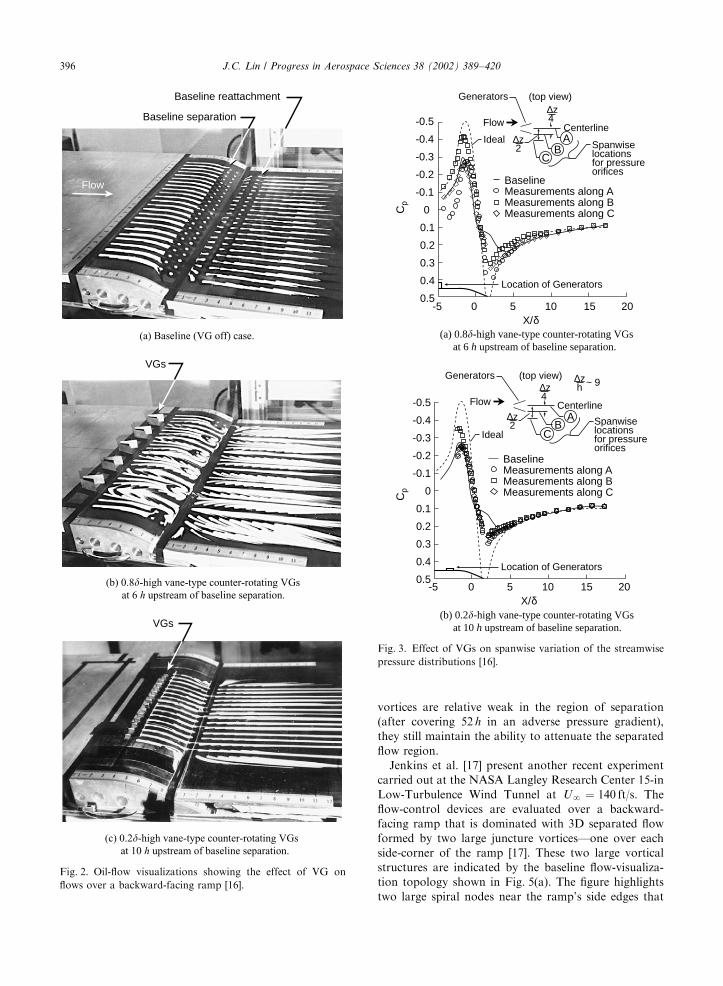
To illustrate the benefit of low-profile VGs, Fig. 2
compares the oil-flow visualization results of baseline
(Fig. 2(a)) with the ‘‘conventional’’ vane-type counter-
rotating VGs (Fig. 2(b)). The conventional VGs exam-
ined are reported to have a h=dB0:8 (rectangular shape,
e=h ¼ 2; Dz=h ¼ 4; b =7151) and placed at approxi-
mately 6 h (B5d) upstream of the baseline separation
(based on the device trailing edge). The results indicate
that each pair of counter-rotating VGs provide mostly
attached flow directly downstream of the ramp trailing
edge (Fig. 2(b)). However, this attached flow is highly
three-dimensional (3D) and pockets of recirculating flow
are still seen on the separation ramp between adjacent
attached-flow regions. This highly 3D nature of the
downstream flow is also an indication that the vortices
produced by the conventional VGs are stronger than
necessary. Weaker vortices (smaller VGs) that produce
just strong enough streamwise vortices to overcome the
separation would be more efficient. This is demonstrated
in Fig. 2(c) by placing vane-type ‘‘low-profile’’ counter-
rotating VGs with h=d ¼ 0:2 (rectangular shape, e=h ¼4; Dz=h ¼ 9; b ¼ 7251) at approximately 10 h (B2d)upstream of baseline separation. The low-profile VGs
successfully reduce the extent of separation by almost
90% [16]. Unlike the conventional VGs, the low-profile
VGs do not adversely affect separation-control effec-
tiveness by generating excessively strong vortices that
cause pockets of recirculating flow via the strong up-
sweep motion of vortices.
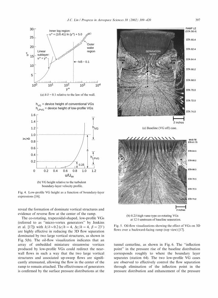
Streamwise pressure distributions for conventional
and low-profile VGs are presented in Figs. 3(a) and (b),
respectively. The figures show that the ‘‘inflection point’’
in the pressure rise of the VG-off baseline (solid line)
corresponds roughly to where the boundary layer
separates. For the VG cases, the surface pressures are
measured at three spanwise locations (i.e., 0, Dz=4; Dz=2)along and downstream of the ramp (see Fig. 3). The
results confirm the effectiveness of the low-profile VGs;
they are observed to be just as effective in eliminating
the inflection point, which is an indication that the
separation has been significantly reduced, as with the
conventional VGs. Fig. 3(b) shows not only significant
improvement in downstream pressure recovery over the
baseline, but also substantial reduction of variations
between the three spanwise locations over the larger
VGs. This is indicative of a greatly reduced ‘‘excess’’ 3D
flow over the conventional VGs. Lin et al. [14] show that
lowering h=d of VGs from 0.2 to 0.1 reduces the
J.C. Lin / Progress in Aerospace Sciences 38 (2002) 389–420392

Table
1
Summary
ofresearchonboundary-layer
flow-separationcontroleffectivenessforlow-profile
VGs
Most
effectiveVG
parametersexamined
Comments
Investigator(s)
(Yearpub.)
Testbed
Typeofstudy
Flow
parameters
VG
type
h=d
e=h
Dz=
hb(deg)
DX
VG=h
Ad
vers
eg
radie
nts
at
low
spee
ds
Lin
etal.
(1990)[13]
Backward-facing
ramp
Wind-tunnel
test
UN
¼132ft/s,
d¼
1:28in
Doublets
0.1
B13
8725
20
DoubletVGswith
h=dB0:1
are
most
effectivein
separationcontrol.
Lin
etal.(1990)
[14];Lin
etal.
(1991)[15]
Backward-facing
ramp
Wind-tunnel
test
UN
¼132ft/s,
d¼
1:28in
Wishbones
0.2
B3
4723
10
Reverse
WishboneVGswith
h/dB
0.2
are
most
effective
inseparationcontrol.
Lin
(1999)[16]
Backward-facing
ramp
Wind-tunnel
test
UN
¼132ft/s,
d¼
1:28in
Counter-rotating
rectangularvanes
0.2
49
725
10
Embedded
stream-w
isevortices
producedby
h=d
B0:2
counter-rotatingvanes
are
most
effectivein
2D
separationcontrol.
Ashillet
al.
(2001)[20]
Bump
Wind-tunnel
test
UN
¼20m/s,
d¼
33mm
Counter-rotating
delta
vanes
Forw
ard
wedges
0.3
0.3
B10
10
12
12
714
714
52
52
Counter-rotatingvanes
with
1hspacingare
most
effective
inreducingtheextentof
separationregion.
Jenkinset
al.
(2002)[17]
Backward-facing
ramp
Wind-tunnel
test
UN
¼140ft/s,
d¼
0:87in
Co-rotating
trapezoid
vanes
0.2
44
23
12and
19
Low-profile
VGsare
the
most
effectivedeviceexamined
in
controlling3D
flow-separation
dominatedbyapairof
juncture
vortices.
Su
per
son
ics
sho
ck-i
nd
uce
dse
pa
rati
on
McC
orm
ick
(1992)[18]
Shock-induced
separationover
flatplate
Wind-tunnel
test
MN
¼1:56
to1.65,
d VG¼
0:389cm
Doublets
0.36
B14
6.4
719
B50
Low-profile
VGsare
more
effectivein
suppressingthe
shock-inducedseparationthan
passivecavitybutalsoresulted
inahigher
shock
loss.
Mounts
and
Barber
(1992)
[19]
Shock-induced
separationover
flatplate
CFD
MN
¼1:40
Ramps
0.33
10
6714
B50
CFD
analysisusing3D
Navier–Stokes
algorithm
indicated
low-profile
VGssignificantly
reduce
thesize
ofreverse
flow
regionandincrease
pressure
recovery.
J.C. Lin / Progress in Aerospace Sciences 38 (2002) 389–420 393

Table
2
Summary
ofvortex
characterizationresearchforlow-profile
VGs
Investigator(s)
Testbed
Typeofstudy
Flow
conditions
VG
type
h=d
e=h
b (deg)
Locationof
crossflow
planes
examined
Comments
Ashillet
al.(2001)
[20];Ashillet
al.
(2002)[21]
Flatplate
Wind-tunnel
test
andCFD
UN
¼10
to40m/s,
dB60mm
Counter-
rotatingvanes
Forw
ard
wedge
Backward
wedge
Single
vane
0.5
0.5
0.5
0.5
B10
10
10
10
714
714
714
10,20,30,45
Upto
15
h
downstream
of
VGs[20];
upto
50
h
downstream
[21]
Acorrelationofvortex
strength
against
device
Reynoldsnumber
hasbeen
developed.Spacingbetween
thevanes
ofcounter-
rotatingVGsreducesthe
mutualvortex
interference.
Vortex
decayanddevice
dragare
reasonably
well
predictedbyaCFD
method
basedonRANSsolutions.
Yaoet
al.
(2002)[22]
Flatplate
Wind-tunnel
Test
UN
¼34m/s,
dB35mm
Single
rectangular
vane
0.2
710,16,23
12stations
coveringover
100
hdownstream
ofVG
Detailed
flowfielddata
are
obtained
foradevice-
inducedem
bedded
streamwisevortex.
Allanet
al.
(2002)[23]
Flatplate
CFD
UN
¼34m/s,
dB45mm
Single
trapezoid
vane
0.2
710,23
15,27,52,and
102
hdownstream
ofVG
CFD
underestimatedthe
peakvorticitybyasmuch
as40%
neartheVG.
J.C. Lin / Progress in Aerospace Sciences 38 (2002) 389–420394

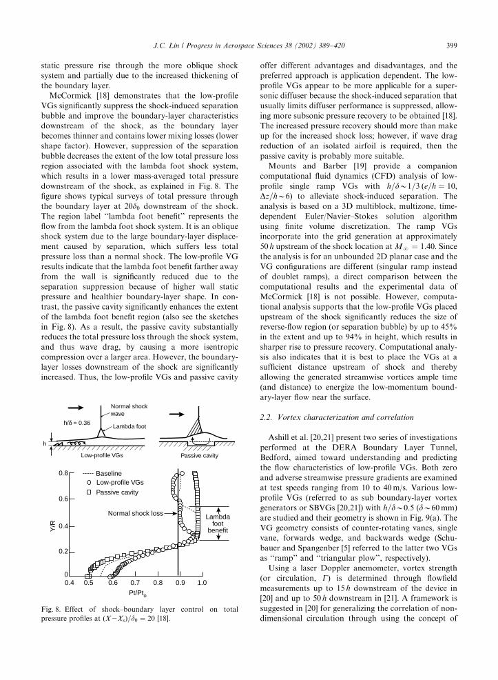
separation-control effectiveness somewhat; however, the
VGs substantially lose their effectiveness when lowering
h=d to less than 0.1. Velocity survey data indicate that a
value of h=do0:1 corresponding to yþ o300, which
approximates where the inner (log) region ends and
the outer (wake) region begins [16], as illustrated in
Fig. 4(a).
The above results demonstrate that for certain
applications where the flow-separation line is relatively
fixed, the low-profile VGs could be more efficient and
effective than the much larger conventional VGs having
a device drag an order-of-magnitude higher. The most
effective range of low-profile VGs is determined to be
about 5–30 h upstream of baseline separation, although
the device-induced streamwise vortices could last up to
100 h. Therefore, the low-profile VGs roughly follow
many of the same guidelines established by Pearcey [7]
for conventional VGs, where the downstream effective-
ness, defined as a multiple of h (instead of d for the
conventional VGs), is thereby reduced due to the lower
height of the device.
Although both Wheeler’s doublet and wishbone VGs
could effectively provide flow mixing over 3 times their
own device height [15], the performance of low-profile
vane-type VGs generally compares favorably with that
of the doublet or wishbone VGs. For example, at
h=dB0:2; the vane-type VGs are slightly more effective
in separation control while incurring less device drag
than the wishbone VGs with equivalent heights. How-
ever, the doublet VGs, because of their extended device
chord length (double rows), could be more effective than
the vane-type VGs when the device height is reduced to
only 10% of the boundary-layer thickness [16]. Simplis-
tically, the effectiveness of the low-profile VGs is at least
partially attributed to the full velocity-profile character-
istic of a turbulent boundary layer. As an example,
Fig. 4(b) shows the typical height of low-profile VG
relative to the boundary-layer velocity profile. Even at a
height of only 0.2d; the local velocity is over 75% of the
free-stream value. Any further increase in height
provides only a moderate increase in local velocity but
dramatically increases the device drag.
Ashill et al. [20] report a recent experiment performed
at the Defence Evaluation and Research Agency
(DERA) Boundary Layer Tunnel, Bedford, to examine
the comparative effectiveness of flow-separation control
over a 2D bump for various low-profile VGs at
UN ¼ 20m/s. Wedge type and counter-rotating delta-
vane VGs with h=dB0:3 (dB33mm, e=hB10; Dz=h ¼12; b ¼ 7141) are located at 52 h upstream of the
baseline separation. All VG devices examined reduce the
extent of the separation region, but the counter-rotating
vanes spaced by 1 h gap are the most effective in
this respect. Although the device-induced streamwise
Region of reduction in reattachment distance
Region of separation delay100
-30-20-10
0102030405060708090
LEB
Uat
+10°
Viet
s’fla
pper
s
Elon
gate
dar
ches
at+1
0°
Swep
t gro
oves
Hel
mho
ltzre
sona
tors
Pass
ive
poro
ussu
rfac
es
Tran
sver
segr
oove
sR
ible
ts
Long
itudi
nal g
roov
es
d~0.
2 sp
anw
ise
cylin
ders
h~0.
1 do
uble
t VG
s
h~0.
2 re
v.w
ishb
one
VGs
h~0.
8 va
neVG
s
h~0.
2 va
neVG
s
% R
educ
tion
inS
epar
atio
n R
egio
n
(a) Summary: relative effectiveness in flow separation control versus device category.
Vane-type VGs
Flow
Wishbone Doublet
Flow
Counter-rotating Co-rotating
Wheeler VGse
e
h
z
e h
z
h
z
h
z
e
(b) VG geometry and device parameters.
Fig. 1. Flow-control effectiveness summary and VG geometry [16].
J.C. Lin / Progress in Aerospace Sciences 38 (2002) 389–420 395
vortices are relative weak in the region of separation
(after covering 52 h in an adverse pressure gradient),
they still maintain the ability to attenuate the separated
flow region.
Jenkins et al. [17] present another recent experiment
carried out at the NASA Langley Research Center 15-in
Low-Turbulence Wind Tunnel at UN ¼ 140 ft/s. The
flow-control devices are evaluated over a backward-
facing ramp that is dominated with 3D separated flow
formed by two large juncture vortices—one over each
side-corner of the ramp [17]. These two large vortical
structures are indicated by the baseline flow-visualiza-
tion topology shown in Fig. 5(a). The figure highlights
two large spiral nodes near the ramp’s side edges that
Baseline separation
Baseline reattachment
Flow
(a) Baseline (VG off) case.
VGs
(b) 0.8�-high vane-type counter-rotating VGs at 6 h upstream of baseline separation.
(c) 0.2�-high vane-type counter-rotating VGs at 10 h upstream of baseline separation.
VGs
Fig. 2. Oil-flow visualizations showing the effect of VG on
flows over a backward-facing ramp [16].
Centerline
Spanwise locations for pressureorifices
AB
C
BaselineMeasurements along AMeasurements along BMeasurements along C
-0.5
-0.4
-0.3
-0.2
-0.1
0
0.1
0.2
0.3
0.4
0.5-5 0 5 10 15 20
Ideal
Generators
Location of Generators
Flow
(top view)
X/δ
∆z
∆z
4
2
(a) 0.8�-high vane-type counter-rotating VGs at 6 h upstream of baseline separation.
(b) 0.2�-high vane-type counter-rotating VGs at 10 h upstream of baseline separation.
Centerline
Spanwise locations for pressureorifices
AB
C
BaselineMeasurements along AMeasurements along BMeasurements along C
-0.5
-0.4
-0.3
-0.2
-0.1
0
0.1
0.2
0.3
0.4
0.5-5 0 5 10 15 20
Ideal
Generators
Location of Generators
Flow
(top view)
X/δ
Cp
Cp
~ 9
2
∆z∆z
∆z
4h
Fig. 3. Effect of VGs on spanwise variation of the streamwise
pressure distributions [16].
J.C. Lin / Progress in Aerospace Sciences 38 (2002) 389–420396
reveal the formation of dominate vortical structures and
evidence of reverse flow at the center of the ramp.
The co-rotating, trapezoidal-shaped, low-profile VGs
(referred to as ‘‘micro-vortex generators’’ by Jenkins
et al. [17]) with h=dB0:2 ðe=h ¼ 4; Dz=h ¼ 4; b ¼ 231)
are highly effective in reducing the 3D flow separation
dominated by two large vortical structures, as shown in
Fig. 5(b). The oil-flow visualization indicates that an
array of embedded miniature streamwise vortices
produced by low-profile VGs could redirect the near-
wall flows in such a way that the two large vortical
structures and associated up-sweep flows are signifi-
cantly attenuated, allowing the flow in the center of the
ramp to remain attached. The effectiveness of generators
is confirmed by the surface pressure distributions at the
tunnel centerline, as shown in Fig. 6. The ‘‘inflection
point’’ in the pressure rise of the baseline distribution
corresponds roughly to where the boundary layer
separates (station 64). The two low-profile VG cases
are observed to effectively control the flow separation
through elimination of the inflection point in the
pressure distribution and enhancement of the pressure
100 101 102 103 104
25
20
15
10
5
Inner log region:u+ = (1/0.41) ln (y+) + 5.0
u+
y+
30
Linear sublayer:u+ = y+
Outer wake region
h/δ ~ 0.1
(a) h/� ~ 0.1 relative to the law of the wall.
1.6
1.4
1.2
1.0
0.8
0.6
0.4
0.2
0.2 0.4 0.6 0.8 1.0 1.20
u/U
y δ
hVG = device height of conventional VGshLPVG = device height of low-profile VGs
δ
∞
0.2δ
hVG
hLPVG
(b) VG height relative to the turbulent boundary-layer velocity profile.
Fig. 4. Low-profile VG height as a function of boundary-layer
expressions [16].
Fig. 5. Oil-flow visualizations showing the effect of VGs on 3D
flows over a backward-facing ramp (top view) [17].
J.C. Lin / Progress in Aerospace Sciences 38 (2002) 389–420 397

recovery. The VGs are clearly more effective than
other flow-control devices examined, such as the micro
bumps and synthetic jets. Results from flowfield
measurements using a 3D stereo digital particle image
velocimetry (PIV) also indicate much stronger VG-
induced streamwise controlling vortices penetrating the
near-wall flows [17]. In addition, there is little difference
between the VG results at the two locations investigated
(12 h and 19 h upstream of baseline separation), which
suggests that the device effectiveness is independent of
position within at least 20 h upstream of baseline
separation.
2.1.2. Supersonic shock-induced separation
For many aerodynamics applications, such as transo-
nic inlets, diffusers, and airfoils, there is frequently a
normal shock interaction with a turbulent boundary
layer that has detrimental effects on drag and pressure
recovery. McCormick [18] reports a basic experimental
study of using low-profile ‘‘Wheeler’s doublet’’ VGs [37]
to control the shock–boundary layer interaction
(Fig. 7(a)). The study shows that the shock strength of
Mach 1.56–1.65 was of sufficient magnitude to produce
a large separation bubble, thus causing substantial
boundary layer losses in an axisymmetric wind tunnel.
McCormick [18] chooses the low-profile doublet VGs
with h=dB0:36 (h ¼ 0:14 cm, e=h ¼ 13:6; Dz=h ¼ 6:4) forthe study because they submerge in the boundary layer
and thus disturb the outer supersonic flow less than
the conventional VGs, which are typically 1.0–1.2d in
height. The doublet VG arrangement, shown in
Fig. 7(a), creates a counter-rotating array of vortices
with the second raw of ramps acting like vortex
‘‘reinforcers’’ to enhance the vortex strength without
an increase in device height. The VGs are located
at approximately 55 h (20d) upstream of the shock
location.
The performances of low-profile VGs are compared
with another flow-control device, the passive cavity, in
terms of the wall static pressure distributions, as shown
in Fig. 7(b). The ‘‘inflection point’’ in the pressure rise of
the baseline distribution (solid line) corresponds roughly
to where the boundary layer separates (corresponding to
zero on the x-axis). The low-profile VGs (circular
symbols) are observed to eliminate the inflection point
in the pressure distribution, which indicates that the
shock-induced separation is significantly suppressed and
thinned [18]. The interaction length (distance from the
initial pressure rise to where the distribution parallels the
ideal curve) is reduced by a factor of 2.3 from 57 to 25d0;where d0 is the undisturbed boundary-layer thickness at
the shock location. The shape of static pressure
distribution for the passive cavity (squares in Fig. 7(b))
is very similar to the baseline case but lower in value,
and the pressure rise is spread over a larger streamwise
(or axial) length. The lower value in static pressure
relative to the baseline is partially due to the decrease in
BaselineVGs (TE at x = 61.75 in.)
Bumps (at x = 61.75 in.).................
Synthetic Jets (at 700 Hz)
-2
0
-1
-1.5
-0.5
50 60 70x station (inches)
Cp
75655545
VGs (TE at x = 60.50 in.)
Fig. 6. Comparison of streamwise pressure distributions for
low-profile VGs, bumps, and synthetic jets [17].
Fig. 7. Shock–boundary layer interaction control using passive
devices [18].
J.C. Lin / Progress in Aerospace Sciences 38 (2002) 389–420398
static pressure rise through the more oblique shock
system and partially due to the increased thickening of
the boundary layer.
McCormick [18] demonstrates that the low-profile
VGs significantly suppress the shock-induced separation
bubble and improve the boundary-layer characteristics
downstream of the shock, as the boundary layer
becomes thinner and contains lower mixing losses (lower
shape factor). However, suppression of the separation
bubble decreases the extent of the low total pressure loss
region associated with the lambda foot shock system,
which results in a lower mass-averaged total pressure
downstream of the shock, as explained in Fig. 8. The
figure shows typical surveys of total pressure through
the boundary layer at 20d0 downstream of the shock.
The region label ‘‘lambda foot benefit’’ represents the
flow from the lambda foot shock system. It is an oblique
shock system due to the large boundary-layer displace-
ment caused by separation, which suffers less total
pressure loss than a normal shock. The low-profile VG
results indicate that the lambda foot benefit farther away
from the wall is significantly reduced due to the
separation suppression because of higher wall static
pressure and healthier boundary-layer shape. In con-
trast, the passive cavity significantly enhances the extent
of the lambda foot benefit region (also see the sketches
in Fig. 8). As a result, the passive cavity substantially
reduces the total pressure loss through the shock system,
and thus wave drag, by causing a more isentropic
compression over a larger area. However, the boundary-
layer losses downstream of the shock are significantly
increased. Thus, the low-profile VGs and passive cavity
offer different advantages and disadvantages, and the
preferred approach is application dependent. The low-
profile VGs appear to be more applicable for a super-
sonic diffuser because the shock-induced separation that
usually limits diffuser performance is suppressed, allow-
ing more subsonic pressure recovery to be obtained [18].
The increased pressure recovery should more than make
up for the increased shock loss; however, if wave drag
reduction of an isolated airfoil is required, then the
passive cavity is probably more suitable.
Mounts and Barber [19] provide a companion
computational fluid dynamics (CFD) analysis of low-
profile single ramp VGs with h=dB1=3 ðe=h ¼ 10;Dz=hB6) to alleviate shock-induced separation. The
analysis is based on a 3D multiblock, multizone, time-
dependent Euler/Navier–Stokes solution algorithm
using finite volume discretization. The ramp VGs
incorporate into the grid generation at approximately
50 h upstream of the shock location at MN ¼ 1:40: Sincethe analysis is for an unbounded 2D planar case and the
VG configurations are different (singular ramp instead
of doublet ramps), a direct comparison between the
computational results and the experimental data of
McCormick [18] is not possible. However, computa-
tional analysis supports that the low-profile VGs placed
upstream of the shock significantly reduces the size of
reverse-flow region (or separation bubble) by up to 45%
in the extent and up to 94% in height, which results in
sharper rise to pressure recovery. Computational analy-
sis also indicates that it is best to place the VGs at a
sufficient distance upstream of shock and thereby
allowing the generated streamwise vortices ample time
(and distance) to energize the low-momentum bound-
ary-layer flow near the surface.
2.2. Vortex characterization and correlation
Ashill et al. [20,21] present two series of investigations
performed at the DERA Boundary Layer Tunnel,
Bedford, aimed toward understanding and predicting
the flow characteristics of low-profile VGs. Both zero
and adverse streamwise pressure gradients are examined
at test speeds ranging from 10 to 40m/s. Various low-
profile VGs (referred to as sub boundary-layer vortex
generators or SBVGs [20,21]) with h=dB0:5 (dB60mm)
are studied and their geometry is shown in Fig. 9(a). The
VG geometry consists of counter-rotating vanes, single
vane, forwards wedge, and backwards wedge (Schu-
bauer and Spangenber [5] referred to the latter two VGs
as ‘‘ramp’’ and ‘‘triangular plow’’, respectively).
Using a laser Doppler anemometer, vortex strength
(or circulation, G) is determined through flowfield
measurements up to 15 h downstream of the device in
[20] and up to 50 h downstream in [21]. A framework is
suggested in [20] for generalizing the correlation of non-
dimensional circulation through using the concept of
Passive cavity
Pt/Pto
Y/R
Normal shock loss Lambdafoot
benefit
Baseline0.8
0.6
0.4
0.2
00.4 0.5 0.6 0.7 0.8 0.9 1.0
Low-profile VGs
h
h/δ = 0.36
Normal shockwave
Lambda foot
Passive cavityLow-profile VGs
Fig. 8. Effect of shock–boundary layer control on total
pressure profiles at ðX2XsÞ=d0 ¼ 20 [18].
J.C. Lin / Progress in Aerospace Sciences 38 (2002) 389–420 399

a device effective height, he [20]. The he is selected by
ensuring that the maximum value of non-dimensional
circulation is independent of device geometry, thereby
combining a family of circulation curves for various
VGs into a single curve, as shown in Fig. 9(b). The figure
shows a single correlation curve of non-dimensional
circulation based on effective height, G5=uthe; as a
function of non-dimensional effective height, hþe(hþ
e ¼ uth=n), for a location 5 h downstream of the
device trailing edge. The correlation is mostly satisfac-
tory for all VGs examined, even though some points are
displaced from the curve that has been fitted through
them. Although the effective height does not have any
particular relationship with any physical dimension of
the devices, the correlation is significant because it
enables the predication of vortex strength just down-
stream of the VGs for a wide range of Reynolds
numbers.
The vortex decay within 15 h downstream of the
device in terms of ln(G=G0:5) versus non-dimensional
streamwise distance, ðx2xtÞ=h (where xt is the device
trailing edge location), for the counter-rotating VG
device with h=dB0:5 is shown in Fig. 10(a). The suffix
0.5 denotes the G value at 0.5 h downstream of the
device. The figure clearly shows that the streamwise
decay of vortex strength for the two 1 and 2 h spaced
counter-rotating vane configurations is an order of
magnitude lower on a logarithmic basis than that for the
forwards wedge, the backwards wedge, and the joined
counter-rotating vanes (zero gap ratio, n ¼ 0 h). Ashill
et al. [20] explain that the close proximity of the counter-
rotating vortices to one another produced by the
forwards wedge and the joint vane device cause mutual
interference between the two vortices that leads to
additional reduction in vortex strength [20]. The even
greater vortex decay of the backwards wedge could be
explained by the stronger influence of wall shear in
further attenuation of vortex strength because the
vortices produced by these devices are always closer to
the wall than for the other devices. The decay rates of
y
x
z
5h
5h
10h 10h
10h
h
h
h
nh
h
Direction of flow Direction of flow
Direction of flow
Direction of flow
h = 5, 15, 30 mm zero pressure gradienth = 10 mm bump tests
h = 30 mm
h = 30 mm
h = 30 mmh = 10 mm bump tests
’Vane’ L = 2h’New Vane’ L = 10h
Forwards wedgeCounter-rotating vanes
(n = 0 joined vanes)
Backwards wedge Single vane
L
(5 + n)h
n = 0, 1, 2
(a) Geometry of SBVGs.
20
15
10
5
0 1000 2000 3000 4000 5000 6000
he+
Γ 5/(
u τh e
)
xx
x+
++
Curve fit
x
+
Forwards wedgeBackwards wedgeJoined counter-rotating vanesCounter-rotating vanes, 1h spaceCounter-rotating vanes, 2h spaceVane (L = 2h), β = -10 deg.Vane (L = 2h), β = 20 deg.Vane (L = 2h), β = 30 deg.Vane (L = 2h), β = 45 deg.New vane (L = 10h), β = -10 deg.New vane (L = 10h), β = 20 deg.New vane (L = 10h), β = 30 deg.New vane (L = 10h), β = 45 deg.
(b) Non-dimensional circulation based on effective height versus non-dimensional effective height.
Fig. 9. Device geometry and correlation of vortex strength against device Reynolds number [20].
J.C. Lin / Progress in Aerospace Sciences 38 (2002) 389–420400

the single rotation devices are similar to those of the two
counter-rotating devices with spaces, except for the vane
at 451 angle of rotation where there is evidence of vortex
bursting.
Vortex decay characteristics of forwards wedge,
counter-rotating vanes, and a single vane have been
established for up to 50 h downstream of the VG devices
[21]. A plot of the vortex strength parameter, G=uth; as afunction of non-dimensional streamwise distance is
shown in Fig. 10(b) for all counter-rotating vanes
(n ¼ 0; 1, 2 h) and the forwards wedge. The vortex
strength of the counter-rotating vane is about twice that
of the forwards wedge. The vortex decay of both the
joined vane and the forwards wedge is clearly larger than
that of the spaced vanes (n ¼ 1; 2 h) for a downstream
distance of less than 15 h from the device, as the vortex
decay of the spaced vanes in this region is hardly
noticeable. Even though the vortex strength of the
joined vane is initially larger than that of the spaced
vanes at 5 h or less downstream, the former is lower than
the latter at 15 h or beyond downstream. Thus, the
streamwise extent of the effectiveness of the joined vanes
is lower than that of spaced vanes.
Ashill et al. [21] report a similar result for an adverse
pressure gradient, although to a lesser degree, since
adverse pressure gradient tends to promote interaction
between the vortices of the spaced vanes. Adverse
pressure gradient has less of an effect on vortex decay
for a single vane than for counter-rotating vanes. In
terms of vortex strength just downstream of the devices,
adverse pressure gradient reduces the effectiveness of
joined vanes more than for vanes with spaces between
them and single vanes. Shape factor results also confirm
that the spaced vanes are more effective than the joined
vane in adverse pressure gradient [21]. Drag measure-
ments of these low-profile devices based on the wake
survey downstream indicate that the forwards wedge has
about 40% of the drag of the counter-rotating vanes in
zero pressure gradient, which is in agreement with the
result of Schubauer and Spangenberg [5] for d-scaleramps and counter-rotating vanes. Measurements in
adverse pressure gradient indicate that increasing the
gap ratio (n) of the counter-rotating vanes reduces their
device drag.
In addition to the experimental data, Fig. 10(a) also
shows CFD predictions of vortex decay for the four
counter-rotating VGs described above. The CFD pre-
diction of vortex strength and decay is made by the
RANSMB method, which solves the Reynolds-averaged
Navier–Stokes (RANS) equations. The k � g turbulence
model used is a modification of the Wilcox k � o model.
The quality of the agreement between CFD and
measurement differs from device to device. For some
devices, the CFD underestimated the vortex strength
just downstream of the device by up to 20%. Vortex
decay is reasonably well predicted by CFD within the
first 5 h downstream of the device but the prediction is
less satisfactory further downstream. This is probably
caused by the difference in computational grid resolu-
tions. The vortex paths of counter-rotating devices are
reasonably well predicted by CFD up to 10 h down-
stream of the device trailing edge [20]. Device drag of
counter-rotating VGs (joined vanes, 1 h spaced vanes,
and forwards wedge) is satisfactorily predicted by CFD
in zero pressure gradient [21].
Another recent collaborative investigation involves
the detailed flowfield measurements [22] and simulations
[23] of an embedded streamwise vortex downstream of a
single low-profile vane-type VG placed within a
turbulent boundary layer over a flat plate. The studies
aim to gain insight and to achieve a more detail
evaluation of the reduced CFD model that uses a
simplified model of the VG vane, where it eliminates
the need to model the device geometry, resulting
in a reduced computational cost, as Bender et al.
[39] describe. Yao et al. [22] discuss the flowfield
xx
x
0 4 8 12 16
-0.2
-0.4
-0.6
-0.8
-1.0
(x - xt)/h
x t= streamwise position of trailing edge of device
ln(Γ
/Γ0.
5)Measurement CFD
Forwards wedge
Backwards wedge
Joined counter-rotating vanes
Counter-rotating vanes, 1h space
Counter-rotating vanes, 2h space
Forwards wedge
Joined counter-rotating vanes
Counter-rotating vanes, 1h space
Counter-rotating vanes, 2h space
x
(a) Vortex decay up to 15 h downstream [20].
Open symbols - first test series
Closed symbols - second test series
Joined vanes
1h spaced vanes
2h spaced vanes
Forwards wedge
50
40
30
20
10
10 20 30 40 50 600 0
(x - xt)/h
Γ/u τ
h
(b) Vortex strength parameter up to 50 h downstream [21].
Fig. 10. Vortex characterization for counter-rotating low-pro-
file VGs with h=d ¼ 0:5:
J.C. Lin / Progress in Aerospace Sciences 38 (2002) 389–420 401

characterization conducted using a 3D stereo digital PIV
system in Langley’s 20-in� 28-in Shear Flow Tunnel at
a free-stream velocity of 34m/s [22]. The PIV measure-
ments are made at 12 crossflow-plane stations, covering
a distance over 100 h, downstream of a vane-type VG
with h=dB0:20 (h ¼ 7mm), e=h ¼ 7; and three b of 101,
161 and 231. The CFD predictions use the NASA
OVERFLOW code [40] that solves the compressible
RANS equations and uses structured grids in an overset
grid framework allowing for the gridding of a complex
geometry. Numerical simulations use the two-equation
(k � o) Shear-Stress Transport model of Menter, which
performs the best [23]. The flow domain is discretized
using five million grid points, including the flow from
the leading edge of the flat plate.
Both experimental and CFD results indicate a rapid
decay of the peak vorticity downstream of the VG,
regardless of the device incidence angle [22,23]. This high
rate of vorticity decay might have important flow-
control implications, especially for applications asso-
ciated with an S-duct type of engine inlet where the rapid
attenuation of streamwise vortices is highly desirable
once the short-range flow-control objective is achieved
(also see Section 3.2.2). For the most part, the CFD
results agree reasonably well with other aspects of the
experiments, such as the predictions of lateral path,
vertical path, and circulation. However, the CFD tends
to under-predict the strength of peak vorticity and over-
predict the vortex size closer to the device (i.e., less than
20 h downstream) by as much as 40% each [22,23].
Hence, there seems to still be a need to improve
numerical scheme and/or modeling of turbulence diffu-
sion for the simulation of an embedded streamwise
vortex produced by the low-profile VG.
3. Aerodynamics performance enhancement
The applied aerodynamics research for the low-profile
VGs also consists of two main categories. The first
includes investigations that focused specifically on flow-
separation control applications for various airfoils and
wings. The second includes those investigations seeking
performance improvement through flow control for
non-airfoil applications. A chronological summary of
representative investigations for each category is pre-
sented in Tables 3 and 4. Both Tables 3 and 4 also
present summaries of the important device parameters
used for flow-separation control (i.e., VG type, h=d; e=h;Dz=h; b; and VG placement), similar to those of Tables 1
and 2. The airfoil/wing investigations consist of four
sub-categories: low-Reynolds number airfoil, high-lift
airfoil, highly swept wings, and transonic airfoil, as
shown in Table 3. In-depth discussions of these airfoil/
wing applications are presented in Sections 3.1.1–3.1.4,
respectively. The non-airfoil investigations include three
sub-categories of aircraft interior noise reduction at
transonic cruise, engine face flow distortion reduction in
compact inlet, and a more efficient overwing fairing (see
Table 4). Detailed discussions of these flow-control
results are presented, respectively, in Sections 3.2.1–
3.2.3. These discussions cover the basic nature of flow
separation, the associated performance issues, and the
resulting benefits of using the low-profile VGs to control
these flow phenomena.
3.1. Airfoil/wing applications
3.1.1. Low-Reynolds number airfoil
Many modern airfoil applications operate in the low-
Reynolds number regime, including remotely piloted
vehicles, high-altitude aircraft, compressor blades, and
wind turbines. Typically, these airfoils operate at a
chord Reynolds number of less than one million and
often experience a laminar separation bubble for angles
of attack below stall. The separation bubble is formed
just downstream of the maximum suction pressure
where the laminar boundary layer separates and
produces an unstable shear layer that rapidly transitions
to a reattached turbulent boundary layer where it
continues to the airfoil trailing edge. Even though small
separation bubbles have little effect upon the lift of an
airfoil, they can create a thicker turbulent boundary
layer that results in a significant drag increase and
thereby adversely affects airfoil efficiency. If the separa-
tion bubble can be reduced, a thinner turbulent
boundary layer downstream would likely be the result,
which could extend the range and endurance of low-
Reynolds number aircraft considerably. One of the first
applications of the low-profile VGs on an airfoil is for
this purpose and was investigated in the early 1990s [24].
Kerho et al. [24] present an experimental investigation
conducted at the USC Dryden wind tunnel to reduce the
separation bubble on a Liebeck LA2573A low-Reynolds
number airfoil through the use of various low-profile
VGs (referred to as submerged vortex generators) and
thereby reducing the airfoil drag. The chord Reynolds
numbers, Rec; of the airfoil examined are between 2 and
5� 105 at a below the stall angle, which represent typical
operating conditions for a low-Reynolds number airfoil.
For controlling the laminar separation bubble, the
generators are located immediately downstream of the
airfoil’s suction pressure peak (at 22% airfoil chord),
and are contained completely within the boundary layer.
The VGs are intended to produce streamwise vortices
that energize the near-wall laminar flow to overcome the
adverse pressure gradient, and consequently, suppress
the laminar separation bubble and prevent the flowfield
from becoming turbulent prematurely. Wishbone VGs
[38] with h=dB0:3 (dB1:6mm) and ramp cone VGs with
h=dB0:4 are two different types of low-profile VGs
tested, along with a conventional-scale wishbone VGs
J.C. Lin / Progress in Aerospace Sciences 38 (2002) 389–420402

Table
3
Summary
ofresearchonairfoil/w
ingaerodynamicsperform
ance
enhancementusinglow-profile
VGs
Investigator(s)
Testbed
Typeofstudy
Flow
parameters
Most
effectiveVG
parametersexamined
Comments
VG
type
he=
hD
z=h
b(deg)
VG
placement
Lo
w-R
eyn
old
sn
um
ber
air
foil
:
Kerhoet
al.
(1993)[24]
Liebeck
LA2573A
low-R
eairfoil
Wind-tunnel
test
Re c=
20,000
to500,000,
d¼
1:6mm
Wishbones
Rampcone
0.3d
0.4d
10
9
65
40
727
60
22%
airfoilchord
(just
up-stream
of
laminarseparation
bubble)
0.48-m
m-highwishboneVGs
canproduce
adesirable
eddy
structure
withoutprematurely
produce
turbulentboundary
layer
resultingin
38%
dragreduction.
Hig
h-l
ift
air
foil
s:
Lin
etal.(1994)
[25];Lin
(1999)
[16]
3-element
high-liftairfoil
Wind-tunnel
test
MN
¼0:2;
Re c
¼5and
9�106
Counter-
rotating
trapezoidal
vanes
0.2d
713
723
25%
flapchord
(30
hupstream
of
separationonflap)
0.04-in-highVGsproduced
10%
lift
increase,50%
drag
reduction,and100%
increase
inL=D
:VGsallow
stowage
insidetheflapwell
duringaircraftcruise.
Klausm
eyer
etal.
(1996)[26]
3-element
high-lift
airfoil
Wind-tunnel
test
UN
¼140ft/s
Counter-
rotating,
trapezoidal
vanes
0.2d
713
723
20%
flapchord
(27
hupstream
of
separationonflap)
0.04-in-highVGsproduced
streamwisevortices
strong
enoughto
controlseparation
withoutdominatingthe
flow
fieldafterward.
Hig
hly
swep
tw
ing
s:
Ashillet
al.(1994)
[27];
Ashillet
al.(1994)
[28];
Ashillet
al.(1995)
[29];
Ashillet
al.(1998)
[30]
601LEdelta
wingmodel
Wind-tunnel
test
MN
¼0:18;
Re c=
4�106
Co-rotating
wires
By
45
B87
B14
50
hfrom
wingLE
0.51-m
m-dia.wireVGs
provided
upto
16%
reductionin
K
anddelayed
theonset
ofbuffet
by10%
inC
L:
Langanand
Samuels(1995)
[31]
401LEdiamond
wingmodel
Wind-tunnel
test
MN
¼0:19;
Re¼
4�
106/m
d=0.1in
Co-rotating
vanes
0.5d
0.5d
4 4
12
9
30
10
Wingtip
Forw
ard/outboard
0.05-in-highco-rotating
VGsprovided
upto
5%
increase
inmax.
L=D
:T
ran
sonic
air
foil
:
Ashillet
al.(2001)
[20]
RAE5243
transonic
airfoil
Wind-tunnel
test
MN
¼0:67
to0.71,
Re c=
19�106
Counter-
rotatingvanes
Forw
ard
wedges
Bdn
Bdn
B10
10
12
12
714
714
70
hupstream
ofshock
location
0.76-m
m-highvanes
spaced
1hapart
producedover
20%
increase
inmaxim
um
lift.
Forw
ardswedges
increased
maxim
um
L=D
by5%
.
J.C. Lin / Progress in Aerospace Sciences 38 (2002) 389–420 403
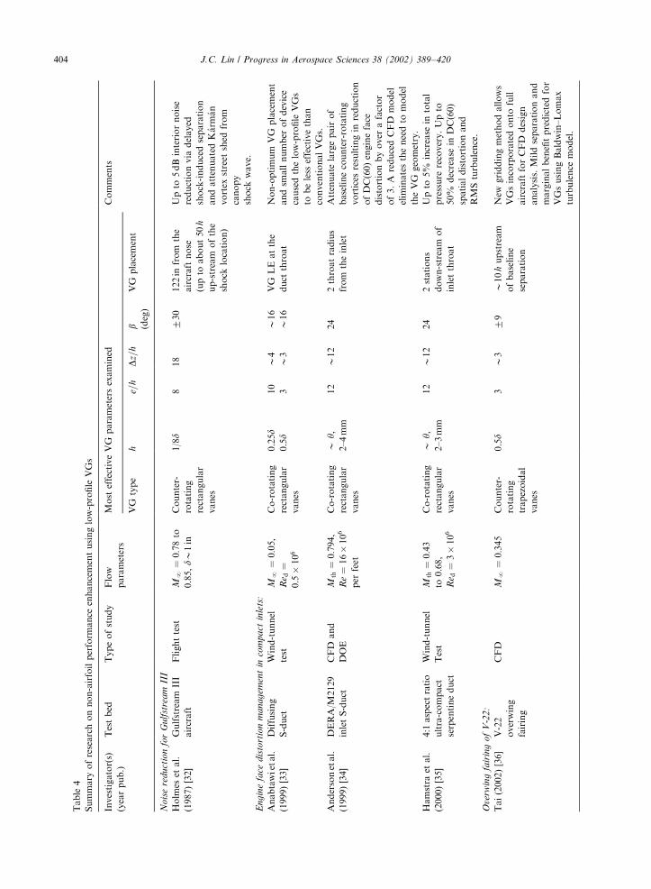
Table
4
Summary
ofresearchonnon-airfoilperform
ance
enhancementusinglow-profile
VGs
Investigator(s)
(yearpub.)
Testbed
Typeofstudy
Flow
parameters
Most
effectiveVG
parametersexamined
Comments
VG
type
he=
hD
z=h
b (deg)
VG
placement
Nois
ere
duct
ion
for
Gulf
stre
am
III
Holm
eset
al.
(1987)[32]
Gulfstream
III
aircraft
Flighttest
MN
¼0:78to
0.85,dB
1in
Counter-
rotating
rectangular
vanes
1/8d
818
730
122in
from
the
aircraftnose
(upto
about50
h
up-stream
ofthe
shock
location)
Upto
5dBinteriornoise
reductionvia
delayed
shock-inducedseparation
andattenuatedK! arm
! an
vortex
street
shed
from
canopy
shock
wave.
Engin
efa
cedis
tort
ion
managem
ent
inco
mpact
inle
ts:
Anabtawietal.
(1999)[33]
Diffusing
S-duct
Wind-tunnel
test
MN
¼0:05;
Re d
¼0:5�
106
Co-rotating
rectangular
vanes
0.25d
0.5d
10
3
B4
B3
B16
B16
VG
LEatthe
duct
throat
Non-optimum
VG
placement
andsm
allnumber
ofdevice
causedthelow-profile
VGs
tobeless
effectivethan
conventionalVGs.
Andersonetal.
(1999)[34]
DERA/M
2129
inletS-duct
CFD
and
DOE
Mth¼
0:794,
Re¼
16�106
per
feet
Co-rotating
rectangular
vanes
By;
2–4mm
12
B12
24
2throatradius
from
theinlet
Attenuate
largepairof
baselinecounter-rotating
vortices
resultingin
reduction
ofDC(60)engineface
distortionbyover
afactor
of3.A
reducedCFD
model
elim
inatestheneedto
model
theVG
geometry.
Hamstra
etal.
(2000)[35]
4:1
aspectratio
ultra-compact
serpentineduct
Wind-tunnel
Test
Mth¼
0:43
to0.68,
Re d
¼3�106
Co-rotating
rectangular
vanes
By;
2–3mm
12
B12
24
2stations
down-stream
of
inletthroat
Upto
5%
increase
intotal
pressure
recovery.Upto
50%
decrease
inDC(60)
spatialdistortionand
RMSturbulence.
Ove
rwin
gfa
irin
go
fV
-22
:
Tai(2002)[36]
V-22
overwing
fairing
CFD
MN
¼0:345
Counter-
rotating
trapezoidal
vanes
0.5d
3B3
79
B10
hupstream
ofbaseline
separation
New
griddingmethodallows
VGsincorporatedonto
full
aircraftforCFD
design
analysis.Mildseparationand
marginalbenefitpredictedfor
VGsusingBaldwin–Lomax
turbulence
model.
J.C. Lin / Progress in Aerospace Sciences 38 (2002) 389–420404

with h=dB0:8; as shown in the sketch of Fig. 11. A
conventional transition (grit) strip comprised of 0.31mm
diameter (d=dB0:2) glass beads is also tested at the same
chord position as the VGs for comparison.
Airfoil drag at the most favorable spacing for each
type of generators is shown in Fig. 11, which clearly
shows the favorable results obtained through the use of
the low-profile VGs. A significant drag reduction is
obtained for all three types of VGs at the design
condition of Rec ¼ 2:35� 105 and a ¼ 41: The h=dB0:8wishbone VGs (Dz=hB11:3) produces a 30% drag
reduction, the h=dB0:4 ramped cone VGs
(Dz=hB39:7) yields a 35% drag reduction, and the
h=dB0:3 wishbone VGs (Dz=h B 64.6) provides the best
result, a 38% drag reduction [24]. All VGs examined
eliminate most of the separation bubble; but the smaller
physical heights of the low-profile h=dB0:3 wishbone
and h=dB0:4 ramp cone VGs provide a smaller profile
drag, and their wider spacing also contributes to
reducing their device drag more than the larger,
h=dB0:8; wishbone VGs. The figure also shows that
the transition strip performs best at a Reynolds number
above 3.75� 105, which corresponds to the optimum
bead diameter needed to induce transition. Although a
24% drag reduction is observed at the design conditions
of Rec ¼ 2:35� 105; increasing the bead size to induce
transition at a lower Reynolds number would make the
bead’s performance unacceptable in the mid and upper
range of Reynolds numbers. Thus, the VGs appear to
provide a much larger range of usefulness [24].
The drag reduction obtained through the use of the
VGs is also obvious over a range of lift coefficients (CL),
as shown in the drag polar represented in Fig. 12 at
Rec ¼ 2:35� 105: A substantial reduction in airfoil drag
by the three types of VGs is seen over the entire
midrange of CL; without any adverse effect (i.e.,
decrease) on the lift. Particularly, this further illustrates
the improved efficiency of the low-profile VGs over the
transition strip. The data converge at high CL near stall
because the separation bubble is so small or nonexistent
that the VGs have very little effect on the airfoil.
3.1.2. High-lift airfoil
In the process of designing a modern commercial
transport aircraft, the performance of its high-lift system
is always a critical issue. Flow separation on multi-
element high-lift airfoils can be a complicated function
of geometry and flight conditions, and can not always be
predicted reliably. Previous reports show that certain
high-lift configurations exhibit boundary-layer separa-
tion on the flap at low angles of attack, while fully
attached flap flow occurs near maximum-lift conditions
[41,42]. In these cases, altering the geometrical config-
uration to avoid low angle-of-attack flap separation
would have a detrimental effect of reducing the
maximum lift. In situations like this, one possible
method of maintaining high maximum-lift values while
attenuating boundary-layer separation at low angles of
attack is to employ flap-mounted, low-profile VGs. The
effectiveness of the low-profile VGs in reducing or
eliminating separation on a typical single-flap three-
element high-lift system at near-flight Reynolds numbers
is demonstrated by Lin [16] and Lin et al. [25]. These
low-profile VGs, because of their small size, are often
referred as ‘‘micro-vortex generators’’ or ‘‘micro VGs’’
[16,25].
The high-lift performance enhancement research
using the low-profile VGs is obtained from tests
conducted during the early 1990s in the Low-Turbulence
Pressure Tunnel at NASA Langley Research Center on
a single-flap three-element airfoil [25,41] at MN ¼ 0:20
xxx x
x
xx x
0.022
0.020
0.018
0.016
0.014
0.012
0.010
0.0081 2 3 4 5 6 7
CD
Rec x 105
α = 4, CL = 0.572
Clean airfoilGlass bead strip1.27 mm VGs, ∆z = 14.3 mm0.48 mm VGs, ∆z = 31.0 mm0.64 mm Cones, ∆z = 25.4 mm
Z
X
X
Y
w
h
Wishbone Ramped Cone
VG Dimensions:
Large Wishbone VGsSmall Wishbone VGsRamped Cone VGs
h w e(mm) (mm) (mm)
1.27 6.00 7.700.48 4.75 4.750.64 4.80 2.78
U∞∆z
e
Fig. 11. Drag versus Reynolds number for low-Re airfoil with
and without laminar flow separation control [24].
xx
x
x
x
x
x
x
xx
Clean airfoil
Glass bead strip
1.27 mm VGs, ∆z = 14.3 mm
0.48 mm VGs, ∆z = 31.0 mm
0.64 mm Cones, ∆z = 25.4 mm
Rec = 235,000
1.5
1.0
0.5
0.0
-0.50.010 0.015 0.020 0.025 0.030 0.035
CD
CL
Fig. 12. Lift versus drag at Rec ¼ 235; 000 for low-Re airfoil
with and without laminar flow separation control [24].
J.C. Lin / Progress in Aerospace Sciences 38 (2002) 389–420 405
and Rec of 5 and 9� 106. These two Reynolds numbers
represent typical 3D wind tunnel and flight conditions,
respectively, at the critical wing station for low-speed
stall of a narrow-body transport. The airfoil has a
reference (stowed) airfoil chord, c; of 22 in and the
model is configured for landing with a slat deflection of
301 and a flap deflection of 351. The maximum-lift
coefficient, CL;max; for this configuration is approxi-
mately 4.5 and occurred at aB211: Flow separation
occurred on the flap over a broad range of angle of
attack (�41pap181) below CL;max: At a typical landing
approach condition (aB81), baseline (VG off) separa-
tion on the flap occurs at approximately 45% of the flap
chord.
Low-profile, counter-rotating, trapezoid-wing VGs
with a height of 0.04 in (h=c ¼ 0:0018; e=h ¼ 7;b ¼ 7231) located at 25% of the flap chord (approxi-
mately 30 h upstream of baseline separation) are
determined to be the ‘‘best-case’’ configuration. For
this case, h=dgfB0:2; where dgf is the ‘‘local’’ boundary-layer thickness defined as the distance between the flap
surface and the near-wall velocity peak of the gap flow
[16,25]. An important practical benefit of this particular
placement is that the low-profile VGs are small enough
to allow stowage within the flap well during cruise to
avoid any device drag penalty when not needed, as
illustrated in Fig. 13. The device spacing between each
generator pair is rearranged such that the down-wash
region is increased and the up-wash region is reduced
from the conventional VG design of Taylor [1] to
maximize the common downward-flow region to further
enhance the wallward momentum transfer for this
application.
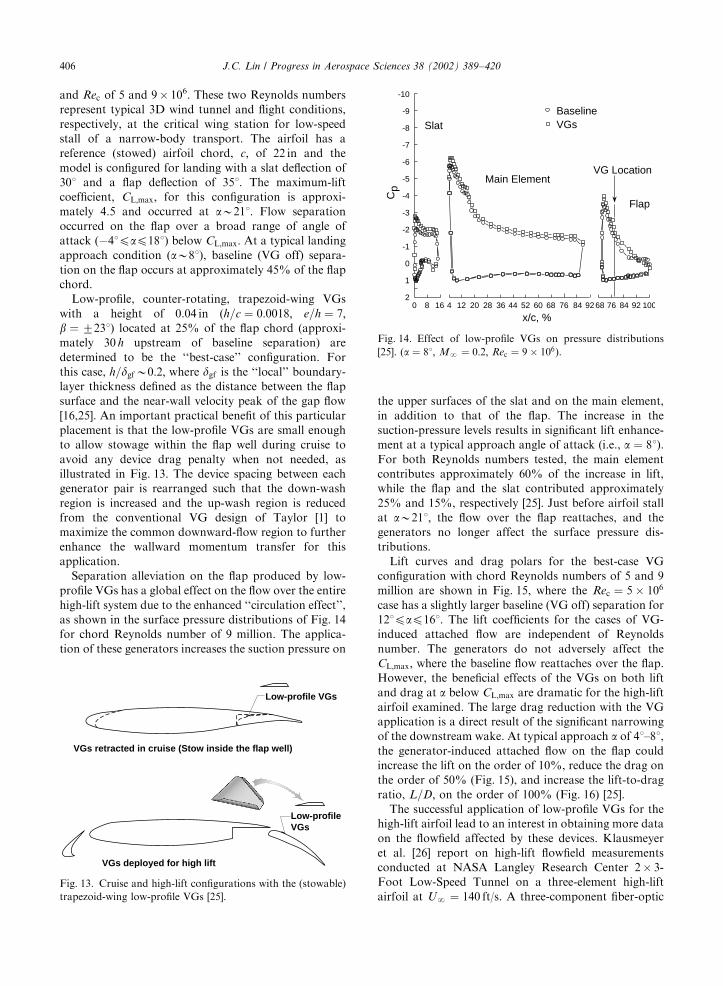
Separation alleviation on the flap produced by low-
profile VGs has a global effect on the flow over the entire
high-lift system due to the enhanced ‘‘circulation effect’’,
as shown in the surface pressure distributions of Fig. 14
for chord Reynolds number of 9 million. The applica-
tion of these generators increases the suction pressure on
the upper surfaces of the slat and on the main element,
in addition to that of the flap. The increase in the
suction-pressure levels results in significant lift enhance-
ment at a typical approach angle of attack (i.e., a ¼ 81).
For both Reynolds numbers tested, the main element
contributes approximately 60% of the increase in lift,
while the flap and the slat contributed approximately
25% and 15%, respectively [25]. Just before airfoil stall
at aB211; the flow over the flap reattaches, and the
generators no longer affect the surface pressure dis-
tributions.
Lift curves and drag polars for the best-case VG
configuration with chord Reynolds numbers of 5 and 9
million are shown in Fig. 15, where the Rec ¼ 5� 106
case has a slightly larger baseline (VG off) separation for
121pap161. The lift coefficients for the cases of VG-
induced attached flow are independent of Reynolds
number. The generators do not adversely affect the
CL;max; where the baseline flow reattaches over the flap.
However, the beneficial effects of the VGs on both lift
and drag at a below CL;max are dramatic for the high-lift
airfoil examined. The large drag reduction with the VG
application is a direct result of the significant narrowing
of the downstream wake. At typical approach a of 41–81,the generator-induced attached flow on the flap could
increase the lift on the order of 10%, reduce the drag on
the order of 50% (Fig. 15), and increase the lift-to-drag
ratio, L=D; on the order of 100% (Fig. 16) [25].
The successful application of low-profile VGs for the
high-lift airfoil lead to an interest in obtaining more data
on the flowfield affected by these devices. Klausmeyer
et al. [26] report on high-lift flowfield measurements
conducted at NASA Langley Research Center 2� 3-
Foot Low-Speed Tunnel on a three-element high-lift
airfoil at UN ¼ 140 ft/s. A three-component fiber-optic
Low-profile VGs
Low-profile VGs
VGs retracted in cruise (Stow inside the flap well)
VGs deployed for high lift
Fig. 13. Cruise and high-lift configurations with the (stowable)
trapezoid-wing low-profile VGs [25].
Main Element
Flap
Slat
VG Location
-10
-9
-8
-7
-6
-5
-4
-3
-2
-1
0
1
20 8 16 4 12 20 28 36 44 52 60 68 76 84 9268 76 84 92 100
Cp
x/c, %
BaselineVGs
Fig. 14. Effect of low-profile VGs on pressure distributions
[25]. (a ¼ 81; MN ¼ 0:2; Rec ¼ 9� 106).
J.C. Lin / Progress in Aerospace Sciences 38 (2002) 389–420406

laser Doppler velocimeter system is used to obtain the
flowfield measurements. The low-profile VGs used in the
study are the same as the counter-rotating trapezoid-
wing device Lin et al. [25] describe. The 0.04-in-high
VGs (h=c ¼ 0:0023) are placed at 20% flap chord.
Baseline (VG off) separation on the flap occurs at
approximately 40% of the flap chord, and the applica-
tion of the VGs on the flap causes a complete flow
reattachment. Comparisons of mean velocity profiles
near mid flap and at the flap trailing edge are shown in
Figs. 17(a) and (b), respectively, for the baseline and the
VG cases. Fig. 17(a) illustrates a marked thinning of the
flap boundary layer due to the generators. Also, higher
velocities are obtained outside of the main-element
wake due to increased circulation. At the trailing edge
Baseline, Rec = 5x10⁶
Baseline, Rec = 9x10⁶
VGs, Rec = 5x10⁶
VGs, Rec = 9x10⁶
5.0
4.5
4.0
3.5
3.0
2.5
2.0
1.5
1.0
0.5
0-8 -4 0 4 8 12 16 20 24 28 0.02 0.03 0.04 0.05 0.06 0.07 0.08
CDα, deg
CL
Fig. 15. Effect of low-profile VGs on lift and drag of a high-lift airfoil [25]. (MN ¼ 0:2).
120
100
80
60
40
20
0
-20-4 0 4 8 12 14 20
∆L/D
,%L/
D,%
α, deg
Fig. 16. Effect of low-profile VGs on L=D of a high-lift airfoil
[25]. (MN ¼ 0:2; Rec ¼ 9� 106).
0.0 0.5 1.0 1.50
20
40
60
80
100
y/h
u/U∞
BaselineVGs
(a) Comparison at mid-flap (50.4% flap chord).
0.0 0.5 1.0 1.50
20
40
60
80
100
y/h
u/U∞
BaselineVGs
(b) Comparison at flap trailing edge.
Fig. 17. Velocity profiles on flap with and without low-profile
VGs [26].
J.C. Lin / Progress in Aerospace Sciences 38 (2002) 389–420 407

(Fig. 17(b)), the main-element wake is washed out by the
recirculation region of the baseline case. The VG case
shows a pronounced main-element wake confluent with
the flap boundary layer. The significant reduction in
velocity defect after flow reattachment would result in a
large drag reduction [26].
A plot of peak streamwise (core) vorticity decay is
given in Fig. 18. The peak vorticity, joxjmax; rapidly
attenuated downstream of the generators. The large
diffusion of vorticity (or vortex concentration) across
core boundaries is probably caused by the steep vorticity
gradients between vortex cores as well as the observed
secondary vorticity induced by flow shearing between
the vortex and the flap surface. In the vicinity of the
baseline separation (i.e., 40% flap chord), vortex/
boundary-layer interactions may also contribute to
further attenuation of vorticity. Fig. 18 illustrates the
streamwise distribution of vortex circulation, G: The
vortex circulation (or strength) drops by a factor of 20
over a distance of approximately 40% of the flap chord
[26]. This is a sign of flow-control efficiency, since the
low-profile VGs could produce streamwise vortices just
strong enough to overcome the baseline separation, yet
not so strong such that the streamwise vortices still
dominated the boundary layer after the flow attachment
is achieved.
3.1.3. Highly swept wings
Ashill et al. [27–30] provide another interesting flow-
control application by using miniature wire segments as
low-profile VGs (referred as SBVGs) to control the
leading-edge flow separation over highly swept wings.
Highly swept wings are wings with sweep-back greater
than 401 that are suitable for stealthy or supersonic
combat or transport aircraft. The research is aimed to
reduce the large lift-dependent drag for the highly swept
wings so the aircraft could maneuver more efficiently at
subsonic speeds. Experiments are performed in the
13 ft� 9 ft Wind Tunnel at DERA, Bedford, on 601
leading-edge delta wing models at a free-stream Mach
number of 0.18 and a Reynolds number based on
geometric mean chord of 4� 106.
Typically in flows over the highly swept wing models,
a 3D or ‘‘ordinary’’ separation line, S1; (described by
Kuchemann [43]) occurs on the highly curved part of the
upper surface (Fig. 19). In addition, another (unrelated)
leading-edge separation line, S2; occurs downstream of
the wing’s leading-edge flow-separation point, P: Theeffect of angle of attack on the streamwise position (xp)
of point P and its consequence are shown in Fig. 19. The
figure shows that for a below about 111 (Type A flows),
where locally induced separation—S2 is unaffected by
the boundary conditions upstream of P—occurs near
the wing tip, the xp changes only slowly with a.However, at higher a (Type B flows), where the
leading-edge separation is upstream dependent (i.e., S2
depends on the boundary-layer conditions upstream of
P), the point P moves more rapidly inboard (and
upstream) with increasing a (Fig. 19). Consequently,
there is a significant increase in the rate that lift-
dependent drag factor, K ; increases with a. There is alsoa noticeable pitch-up at aB141 (Fig. 19). This rapid
forward movement of upstream-dependent leading-edge
separation with increasing a would have harmful
consequences for lateral stability characteristics. Hence
the role of the ordinary separation line S1 is of great
significance, and by moving S1 and P in the downstream
direction using the low-profile VGs for the upstream-
dependent (Type B) separation may result in significant
beneficial effects.
The low-profile VGs investigated are small wires with
a diameter, d (d ¼ 0:51mm, e=d ¼ 45), approximately
equal to the local turbulent boundary layer’s displace-
ment thickness, d�; and set at an angle of about 161
relative to the wing leading edge (Fig. 20). The wire VGs
are tested singly and multiply near the upper wing’s
leading edge. The detailed location of the wires is
specified in Ashill et al. [27–29]. Each wire is arranged so
as to induce a streamwise vortex, the rotational sense of
which resists the ‘‘drift’’ of the boundary-layer flow
toward the point P and to promote the flow toward the
separation line deep within the boundary layer. Oil-flow
studies indicate that the wires act to convert boundary-
layer vorticity into streamwise vorticity. The wire does
this by inducing a ‘‘scarf’’ vortex separation upstream of
the wire’s flat front face. The leeward part of this scarf
vortex rolled-up sheet provides the necessary component
of streamwise vorticity (Fig. 20). The side of the wire
ensures that the windward part of the rolled-up sheet
does not interfere with the leeward sheet.
Fig. 21 shows results for the percentage reduction in
K due to the wire VGs for the fixed-camber wing plotted
against lift coefficient for various numbers and arrange-
ments of wires. The figure shows that the range in which
the wire generators are effective is limited to lift
% Flap Chord
Γ (f
t2 /s)
30 40 50 60 70
Left vortexRight vortex
7
6
5
4
3
2
1
0
0.80.70.60.50.40.30.20.10.0
×104
|ωx| m
ax (1
/s)
Fig. 18. Streamwise decay of peak vorticity and vortex circula-
tion [26].
J.C. Lin / Progress in Aerospace Sciences 38 (2002) 389–420408

coefficients between approximately 0.43 and 0.63
(121pap161); in addition, the maximum K reduction
of 16% occurs with 28 wires at CLB0:5: Any further
increase in wire number resulted in a slight decrease in
the benefit because of a likely increase in the mutual
interference between the wires. Ashill et al. [30] report
that studies at DERA indicate a 16% reduction in K can
result in significant savings in fleet costs for combat
aircraft and reduction in takeoff and landing noise for
supersonic transport aircraft.
Ashill et al. [27] indicate that a major part of the
increase leading-edge thrust, which provides the reduc-
tion in K ; comes from the reorganization of the leading-
edge separated flow downstream of the point P and
moving point P downstream. The wire VGs tighten the
leading-edge vortex and move it closer to the forward-
facing surface near the wing leading edge, resulting in
increased leading-edge thrust. Furthermore, Fig. 22
shows the effect of the wire generators on the wing-tip
acceleration for a particular mode of vibration and for
1.0XX
P
S2S
2
S1
S1
0.8
0.6
0.4
0.2
0
1.8
1.6
1.4
1.2
1
8
8
10
10
12
12
14
14
16
16
18
18
20
-0.002
0.002
0.004
0
α, deg
α, deg
8 10 12 14 16 18 α, deg
Xp
Root LE
Cm’
0.3 0.4 0.5 0.6 0.7CLCL
0.3 0.4 0.5 0.6 0.7
Type A Type B
Locally-induced:Type A flows
= CmCm’ - (0.054CL + 0.0185)
Type A Type B Type A Type B
K
Reduced pitching-moment coefficientLift-dependent drag factor
Axial position of separation point P
Sketch of LE separation type (top view)
60°
S1 Upper surface separation lineS2 LE separation line
Upstream-dependent:Type B flows
P
Fig. 19. Leading-edge flows on highly swept wing requiring control [28,29].
Leading edge
'Scarf' vortex
Lee-side part of'Scarf' vortex
Path of separationline with control
Path of separationline without control
Wire VG
25.4 mm
22.9 mm
16.3°
Leading edge
Wire VG
Wire VG geometry
Fig. 20. Surface flows close to a wire VG showing its effect on flow approaching separation line [27].
J.C. Lin / Progress in Aerospace Sciences 38 (2002) 389–420 409
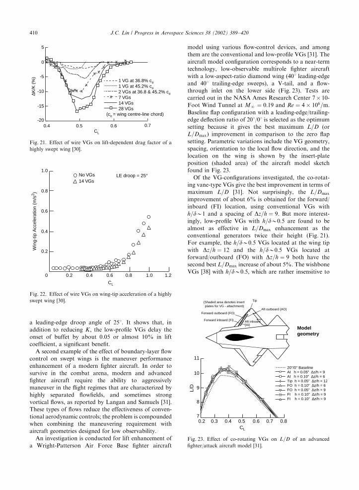
a leading-edge droop angle of 251. It shows that, in
addition to reducing K ; the low-profile VGs delay the
onset of buffet by about 0.05 or almost 10% in lift
coefficient, a significant benefit.
A second example of the effect of boundary-layer flow
control on swept wings is the maneuver performance
enhancement of a modern fighter aircraft. In order to
survive in the combat arena, modern and advanced
fighter aircraft require the ability to aggressively
maneuver in the flight regimes that are characterized by
highly separated flowfields, and sometimes strong
vortical flows, as reported by Langan and Samuels [31].
These types of flows reduce the effectiveness of conven-
tional aerodynamic controls; the problem is compounded
when combining the maneuvering requirement with
aircraft geometries designed for low observability.
An investigation is conducted for lift enhancement of
a Wright-Patterson Air Force Base fighter aircraft
model using various flow-control devices, and among
them are the conventional and low-profile VGs [31]. The
aircraft model configuration corresponds to a near-term
technology, low-observable multirole fighter aircraft
with a low-aspect-ratio diamond wing (401 leading-edge
and 401 trailing-edge sweeps), a V-tail, and a flow-
through inlet on the lower side (Fig. 23). Tests are
carried out in the NASA Ames Research Center 7� 10-
Foot Wind Tunnel at MN ¼ 0:19 and Re ¼ 4� 106=m:Baseline flap configuration with a leading-edge/trailing-
edge deflection ratio of 201/01 is selected as the optimum
setting because it gives the best maximum L=D (or
L=Dmax) improvement in comparison to the zero flap
setting. Parametric variations include the VG geometry,
spacing, orientation to the local flow direction, and the
location on the wing is shown by the insert-plate
position (shaded area) of the aircraft model sketch
found in Fig. 23.
Of the VG-configurations investigated, the co-rotat-
ing vane-type VGs give the best improvement in terms of
maximum L=D [31]. Not surprisingly, the L=Dmax
improvement of about 6% is obtained for the forward/
inboard (FI) location, using conventional VGs with
h=dB1 and a spacing of Dz=h ¼ 9: But more interest-
ingly, low-profile VGs with h=dB0:5 are found to be
almost as effective in L=Dmax enhancement as the
conventional generators twice their height (Fig. 21).
For example, the h=dB0:5 VGs located at the wing tip
with Dz=h ¼ 12 and the h=dB0:5 VGs located at
forward/outboard (FO) with Dz=h ¼ 9 both have the
second best L=Dmax increase of about 5%. The wishbone
VGs [38] with h=dB0:5; which are rather insensitive to
5
0
-5
-10
-15
-200.5 0.6
CL
∆K/K
(%
)
xxxx xx
x
x
x
xxx
x xx
x x x
0.4
1 VG at 36.8% co1 VG at 45.2% co2 VGs at 36.8 & 45.2% co7 VGs14 VGs28 VGs
0.7
(co = wing centre-line chord)
Fig. 21. Effect of wire VGs on lift-dependent drag factor of a
highly swept wing [30].
1.0
0.8
0.6
0.4
0.2
0 0.2 0.4 0.6
CL
0.8 1.0 1.2
Win
g-tip
Acc
eler
atio
n (m
/s2 )
No VGs14 VGs
LE droop = 25°
Fig. 22. Effect of wire VGs on wing-tip acceleration of a highly
swept wing [30].
11
10
9
8
70.2 0.3 0.4 0.5 0.6 0.7 0.8
CL
L/D
20°/0° BaselineAI h = 0.05" ∆z/h = 9AI h = 0.10" ∆z/h = 6Tip h = 0.05" ∆z/h = 12FO h = 0.10" ∆z/h = 6FO h = 0.05" ∆z/h = 9FI h = 0.10" ∆z/h = 9FI h = 0.10" ∆z/h = 9
(Shaded area denotes insert plates for VG - attachment)
Tip
Aft outboard (AO)Forward outboard (FO)
Aft inboard (AI)
Forward inboard (FI)
Model geometry
Fig. 23. Effect of co-rotating VGs on L=D of an advanced
fighter/attack aircraft model [31].
J.C. Lin / Progress in Aerospace Sciences 38 (2002) 389–420410

the local flow direction, produce about the same
effectiveness. For this swept-wing application, the
counter-rotating vane-type VGs are less effective than
those of the co-rotating arrangements in increasing the
L=Dmax: The best-case improvement of counter rotating
VGs is about 3.5% [31].
3.1.4. Transonic airfoil
An aircraft needs to generate higher lift coefficients
over its wings to achieve the required performance
during high-speed turning maneuvers because the
vertical component of the lift available to counter the
aircraft’s weight is substantially reduced. As a result of
increased lift requirements, there often can be very large
adverse pressure gradients in the streamwise direction as
well as shock waves over the wing’s upper surface. A
possible consequence is that the boundary layer
separates, causing a loss of lift and lateral control, high
drag, and buffeting [20]. An obvious solution is the use
of a low-drag device to control the boundary-layer
separation.
Ashill et al. [20] report on tests conducted on a RAE
5243 airfoil model in the 8 ft High-Speed Wind Tunnel
at DERA, Bedford, using the low-profile VGs (referred
to as SBVGs) for lift enhancement [20]. The airfoil,
originally designed for natural laminar flow at a lift
coefficient of 0.5 and a Mach number of 0.68, has a
chord of 0.635m and 14% maximum thickness to chord
ratio. The shock wave on the upper surface of this airfoil
moves only a small distance with changes in Mach
number and angle of attack, which is a good candidate
for the low-profile VG application, and is located at
about 55% chord. The tests are performed for Mach
numbers between 0.67 and 0.71 at a Reynolds number
based on chord of 19� 106. The counter-rotating vanes
spaced apart by 1 h and forwards wedges are two types
of low-profile VGs used for the investigation (Fig. 9(a)).
The devices have similar geometry to their counterparts
in the low-speed study described in Section 2.2, and the
lateral spacing between them is 12 h. The VGs has a
device height of 0.76mm or approximately equal to the
boundary-layer displacement thickness at the device
location (i.e., h=d �B1). The generators are placed as an
array at 46.5% chord, which is approximately equal to
70 h upstream of the presumed shock location.
Application of low-profile VGs clearly demonstrates
a performance improvement in lift. Fig. 24(a) shows
normal force coefficient as a function of a for the
baseline (uncontrolled) configuration and the two cases
with the VGs at a Mach number of 0.71 (i.e., 0.03 Mach
higher than the design value). The split vanes give at
least 20% higher maximum normal force (or lift)
compared with baseline, while the forwards wedges
produce about a 10% increase in maximum lift [20].
Fig. 24(b) shows the effect of the generators on L=D:The maximum L=D is obtained with the wedges at a lift
coefficient of 0.4, which is below that for rapid decrease
in pressure near the trailing edge. This is about 5%
higher than that of the baseline. The largest values of
L=D at lift coefficients above 0.7 are achieved with split
vanes, a result that was expected from examining
Fig. 24(a)).
The effect of the low-profile VGs on surface pressure
distributions at a given lift coefficient of 0.4 is shown in
Fig. 25(a). The strength of the shock, indicated by the
suction pressure level just upstream of the shock wave,
seems to be lowest with the wedges. It is speculated that
compression wave induced by wedges, in the presence of
the boundary layer, weaken the shock wave. On the
other hand, the split vanes produce the largest shock
strength, which is possibly a result of the effect of the
vanes in reducing the growth of the boundary-layer
upstream of the shock (also see discussions in Section
2.1.2). This would result in compression waves of
decreased strength in this region [20]. Fig. 25(b) shows
that at a lift coefficient of 0.7 (baseline data not
available) the split vanes reduce the extent of the
separated flow relative to that of the wedges, as expected
from viewing Figs. 24(a) and (b).
BaselineWedgesSplit Vanes
-1 0 12 34-2-0.1
α, deg
0.1
0.2
0.3
0.4
0.5
0.6
0.7
0.80.9
0
CN
(a) Normal force as a function of airfoil angle of attack.
BaselineWedgesSplit Vanes
L/D
0 0.1 0.2 0.3 0.4 0.5 0.6 0.7 0.8CL
0.4
0.3
0.2
0.1
0.0
(b) L/D versus lift coefficient.
Fig. 24. Effect of low-profile VGs on lift and drag of a
transonic airfoil at MN ¼ 0:71 [20].
J.C. Lin / Progress in Aerospace Sciences 38 (2002) 389–420 411

3.2. Non-airfoil applications
3.2.1. Noise reduction for Gulfstream III
One of the earliest practical applications of the low-
profile VGs is not intended for an airfoil or wing, but
instead, it is for interior noise reduction of the Gulf-
stream III aircraft [32]. From research in the mid-1980s,
it is discovered that a small region of shock-induced
boundary-layer flow separation exists at high Mach
numbers on the canopy of the Gulfstream III aircraft
(Fig. 26(a)). Downstream of the separated flow region
an externally mounted VHF blade antenna generates a
vibration with a frequency spike at 240Hz. This
vibration appears to be produced by an unsteady vortex
separation that might be excited by a von K!arm!an
vortex street shed from the canopy shock wave. As a
result, a low-frequency noise known as ‘‘Mach rumble’’
is observed in the cabin of the Gulfstream III aircraft at
high Mach number cruise conditions, and the interior
noise tends to intensify with an increase in Mach
number [32].
Inspired by the work of Kuethe [11], in which wave-
type low-profile VGs are successful in suppressing the
formation of the K!arm!an vortex street in the wake
region, Holmes et al. [32] select low-profile, 1/8-in-high
VGs (referred as SBVGs) for this flow-control applica-
tion. Furthermore, the local flow over the canopy being
supersonic also indicates that conventional VGs would
create stronger shocks and hence additional noise
sources, whereas the low-profile VGs function in the
lower portion of the boundary layer in a subsonic flow
region. The selected device height is about 1/8 of the
predicted boundary-layer thickness (dB1 in). The small
device height also means associated device drag and
aesthetic impacts are minimized [32]. As discussed earlier
in Section 2.1.1, their small size means that the low-
profile VGs have a somewhat limited range of down-
stream effectiveness. Hence, placement of these VGs
relative to the shock wave becomes more critical than it
would be for the conventional VGs. The geometry of the
low-profile VGs examined is shown in Fig. 26(b), which
consists of a row of counter-rotating vane pair with
e=h ¼ 8; Dz=h ¼ 18; and b ¼ 7301: Both e=h and Dz=h
are about a factor of 4 higher and b is 141 higher than
the classical design guideline for the conventional VGs.
This combination of a relative longer vane chord, wider
spacing, and higher incidence angle ensure the genera-
tion of strong embedded streamwise vortices as well as
reduce the overall number of devices required for the
application (lower device drag). See Fig. 26 for device
location and geometry. Fig. 26(a) also shows the
placement of noise and vibration instruments at six
centerline locations inside the fuselage of a Gulfstream
III flight-test aircraft.
Installing a number of low-profile VGs to the fuselage
upstream of the shock very effectively reduces both the
Mach rumble and the vibration. Acting much like the
conventional VGs, the low-profile VGs effectively delay
0.4
0.2
0
-0.2
-0.4
-0.6
-0.8
-1.0
-1.2
-1.4
-1.6
x/c0.4 0.6 0.8 1.0
0.4
0.2
0
-0.2
-0.4
-0.6
-0.8
-1.0
-1.2
-1.4
-1.6
x/c0.2 0.4 0.6 0.8 1.0
CP
(a) CL = 0.4 (b) CL = 0.7
BaselineWedgesSplit Vanes
0.20 0
Fig. 25. Effect of low-profile VGs on pressure distributions of a
transonic airfoil at MN ¼ 0:71 [20].
Vortex generatorsVHF antenna
AccelerometeersMicrophones
(a) Location of VGs and noise and vibration instruments on the fuselage of Gulfsteam III.
1.10
2.25
Top view
Front view
Base plate
VanesHeight0.125
Fuselagestation 122
Fuselagesurface
Dimensions in inches
Flow direction
(b) Geometry of low-profile VGs on the aircraft fuselage.
Fig. 26. Low-profile VGs for interior noise reduction on a
Gulfstream III flight-test aircraft [32].
J.C. Lin / Progress in Aerospace Sciences 38 (2002) 389–420412
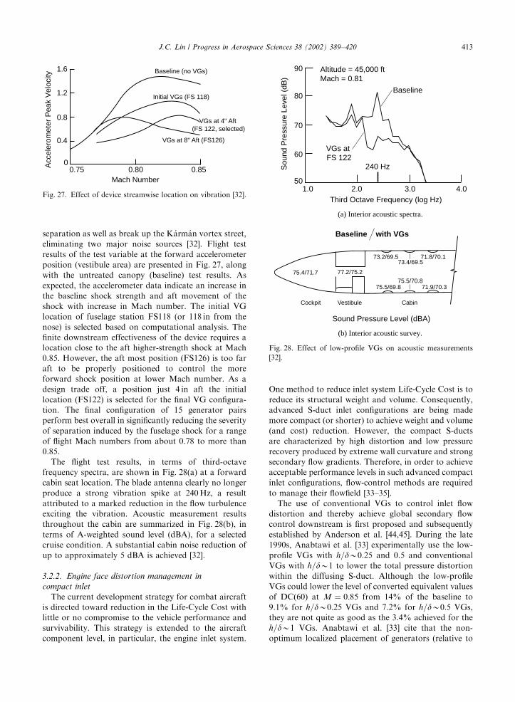
separation as well as break up the K!arm!an vortex street,
eliminating two major noise sources [32]. Flight test
results of the test variable at the forward accelerometer
position (vestibule area) are presented in Fig. 27, along
with the untreated canopy (baseline) test results. As
expected, the accelerometer data indicate an increase in
the baseline shock strength and aft movement of the
shock with increase in Mach number. The initial VG
location of fuselage station FS118 (or 118 in from the
nose) is selected based on computational analysis. The
finite downstream effectiveness of the device requires a
location close to the aft higher-strength shock at Mach
0.85. However, the aft most position (FS126) is too far
aft to be properly positioned to control the more
forward shock position at lower Mach number. As a
design trade off, a position just 4 in aft the initial
location (FS122) is selected for the final VG configura-
tion. The final configuration of 15 generator pairs
perform best overall in significantly reducing the severity
of separation induced by the fuselage shock for a range
of flight Mach numbers from about 0.78 to more than
0.85.
The flight test results, in terms of third-octave
frequency spectra, are shown in Fig. 28(a) at a forward
cabin seat location. The blade antenna clearly no longer
produce a strong vibration spike at 240Hz, a result
attributed to a marked reduction in the flow turbulence
exciting the vibration. Acoustic measurement results
throughout the cabin are summarized in Fig. 28(b), in
terms of A-weighted sound level (dBA), for a selected
cruise condition. A substantial cabin noise reduction of
up to approximately 5 dBA is achieved [32].
3.2.2. Engine face distortion management in
compact inlet
The current development strategy for combat aircraft
is directed toward reduction in the Life-Cycle Cost with
little or no compromise to the vehicle performance and
survivability. This strategy is extended to the aircraft
component level, in particular, the engine inlet system.
One method to reduce inlet system Life-Cycle Cost is to
reduce its structural weight and volume. Consequently,
advanced S-duct inlet configurations are being made
more compact (or shorter) to achieve weight and volume
(and cost) reduction. However, the compact S-ducts
are characterized by high distortion and low pressure
recovery produced by extreme wall curvature and strong
secondary flow gradients. Therefore, in order to achieve
acceptable performance levels in such advanced compact
inlet configurations, flow-control methods are required
to manage their flowfield [33–35].
The use of conventional VGs to control inlet flow
distortion and thereby achieve global secondary flow
control downstream is first proposed and subsequently
established by Anderson et al. [44,45]. During the late
1990s, Anabtawi et al. [33] experimentally use the low-
profile VGs with h=dB0:25 and 0.5 and conventional
VGs with h=dB1 to lower the total pressure distortion
within the diffusing S-duct. Although the low-profile
VGs could lower the level of converted equivalent values
of DC(60) at M ¼ 0:85 from 14% of the baseline to
9.1% for h=dB0:25 VGs and 7.2% for h=dB0:5 VGs,
they are not quite as good as the 3.4% achieved for the
h=dB1 VGs. Anabtawi et al. [33] cite that the non-
optimum localized placement of generators (relative to
Mach Number0.80 0.850.75
0
0.4
0.8
1.2
1.6
Acc
eler
omet
er P
eak
Vel
ocity
Baseline (no VGs)
Initial VGs (FS 118)
VGs at 4" Aft (FS 122, selected)
VGs at 8" Aft (FS126)
Fig. 27. Effect of device streamwise location on vibration [32].
90
80
70
60
501.0 2.0 3.0 4.0
Third Octave Frequency (log Hz)
Sou
nd P
ress
ure
Leve
l (dB
)
Altitude = 45,000 ftMach = 0.81
Baseline
VGs at FS 122
240 Hz
(a) Interior acoustic spectra.
75.4/71.7 77.2/75.2
75.5/69.8
73.2/69.5 71.8/70.173.4/69.5
71.9/70.375.5/70.8
Baseline with VGs
Cockpit Vestibule Cabin
Sound Pressure Level (dBA)
(b) Interior acoustic survey.
Fig. 28. Effect of low-profile VGs on acoustic measurements
[32].
J.C. Lin / Progress in Aerospace Sciences 38 (2002) 389–420 413

flow separation) and the small number of devices used
may be the reason for the ineffectiveness of the smaller
VGs. Placing the low-profile VGs inside and around the
surface of the duct closer to region of separation in an
attempt to evenly redistribute the boundary-layer flow
around the circumference of the fan face is suggested as
an improvement [33].
At about the same time, Anderson et al. [34] use CFD
and design of experiment (DOE) optimization proce-
dures to examine the effect of using low-profile co-
rotating vane VGs to ‘‘globally’’ manage the entire inlet
flowfield. The DOE method [46] is applied in the form of
a predetermined design array that defines a series of
experiments that can evaluate the effects of each design
variable over its range of values. The low-profile VGs
with a device height on the order of boundary-layer
momentum thickness, y; are found to effectively spread
out (circumferentially) the near-wall low-momentum
fluids that suppress 3D flow separation from the wall.
The research is done as a necessary prerequisite to define
the controlling properties for the future applications of
micro electrical mechanical systems (MEMS) actuators.
These actuators share the same objective of effectively
managing the entire flowfield of compact inlets using the
similar approach of ‘‘minimal’’ near-wall protuberances
as the low-profile VGs, hence the VG vanes Anderson
et al. [34] used are called the MEMS-scale effectors.
The CFD investigations are conducted on the DERA/
M2129 inlet S-duct at Mth;¼ 0:8 and Re ¼ 16� 106=ft,using the Lockheed Martin Tactical Aircraft Systems’
Full Navier-Stokes FALCON code [39] that includes a
vane VG (effector) model. Two types of gridding
methods are used for comparison: the effector analysis
grid and the effector model grid. The difference between
the two methods is that the individual vanes were not
gridded for the effector model grid. The latter uses a
simplified model of the VG vane by the means of the
boundary condition approach rather than fully gridding
the VGs. As a result, the effector model grid contains
539,700 fewer nodal points (72% less) than the effector
analysis grid and requires less computational cost [34].
The reference effector installation is defined as a VG
configuration such that the vane height is between 2 and
4mm above the duct walls, or hBy: Fig. 29(a) illustratesthe Full Navier–Stokes baseline solution for the 3D
flow-separation topography associated with vortex lift-
off in the M2129 inlet S-duct. The figure shows the
development of a pair of counter-rotating vortices that
form in the forward section of the duct, which leads to
vortex lift-off in the aft section. It is this lift-off or 3D
separation phenomenon that is the primary distortion
mechanism in compact inlet systems, and thereby the
flow phenomena that must be controlled. The purpose
of the low-profile co-rotating VGs is to create vortices
that merge quickly to form a single overall secondary
flow pattern that remains within the ‘‘thin’’ boundary
layer next to the wall. It is this induced secondary flow
pattern adjacent to the wall that prevents the formation
of the pair of counter-rotating vortices described in
Fig. 29(a), and consequently the undesirable effects of
the vortex lift-off phenomena on engine face flow
distortion. Producing this single overall secondary flow
pattern is the fundamental flow mechanism that allows
the entire inlet flowfield to be managed by controlling
(or redistributing) the flow within a thin layer adjacent
to the walls, as reported by Anderson et al. [34].
The baseline engine face total pressure recovery
contours obtained from the FFA/Sweden T1500 High
Fig. 29. Effect of low-profiles VGs in a compact (M2129) inlet
S-duct [34].
J.C. Lin / Progress in Aerospace Sciences 38 (2002) 389–420414

Reynolds Number Wind Tunnel are shown in Fig. 29(b).
The engine face flow distortion caused by the pair of
counter-rotating vortices described in Fig. 29(a) are
clearly seen in the pressure contours. Based on results
using CFD and DOE optimization procedures, it is
concluded that the performance of the low-profile VGs
is very sensitive to the device arrangement (design).
There appears to be an optimum number of VGs that
can be installed in any installation band, and this value
is 36 for optimal analysis and 34 for optimal model.
Beyond that optimum number, the reduction in engine
face DC(60) distortion is negligible. In any installation
arrangement, there is an optimum strength directly
associated with device angle of incidence (b) and the
values of b are 241 and 281, respectively, for optimal
analysis and optimal model. The optimum device
strength does not depend strongly on the number of
device within the installation itself. The device chord
length is found to be a very effective parameter in
reducing engine face flow distortion, and the device
chord length non-dimensionalized by throat radius is
0.168 for both optimal analysis and optimal model [34].
A comparison of the total pressure recovery contours
using optimal analysis and optimal model methods is
shown in Fig. 29(b). There is dramatic improvement
over the baseline, although little difference appears both
qualitatively and quantitatively between the two com-
putational methods. Of course, the optimal model
method has the advantage of using 72% less nodal
points. As the large pair of counter-rotating vortices is
eliminated from the bottom duct surface of the baseline
case, the DC(60) engine face distortion is predicted to
reduce by a factor of 3.5, from 0.336 to 0.096 using the
most conservative results of the optimum analysis
method.
A subsequent experimental verification test conducted
at the W1B Subsonic Diffuser Test Facility at NASA
Glenn Research Center examines the effect of low-
profile VGs on a 4:1 aspect ratio ultra-compact (length/
diameter=2.5) serpentine duct that fully obscures line-
of-sight view of the engine face [35]. The throat Mach
number for the test ranges from 0.43 to 0.68, and the
Reynolds number based on ‘‘aerodynamic interface
plane’’ diameter, Red; is approximately 3� 106. Two
arrays of 36 co-rotating low-profile VGs (referred to as
microvanes by Hamstra et al. [35]) with device height
ranging from 2 to 3mm are used.
Substantial improvements in all inlet system-level
metrics are found for the low-profile VGs across the
tested range. A comparison of pressure recovery,
distortion, and RMS turbulent levels for the baseline,
low-profile VG, and a microjet configuration is shown in
Fig. 30. The low-profile VGs provide dramatic improve-
ment over the baseline and microjet configurations in
both pressure recovery and turbulence over the entire
test range, and in distortion up to a throat Mach
number of 0.60. In particular, total pressure recovery is
increased by as much as 5%, and DC(60) spatial
distortion and RMS turbulence are decreased by as
much as 50% [35]. CFD predictions compare very well
with experimental data for substantial performance
improvement through the application of low-profile
VGs.
3.2.3. Overwing fairing of V-22
Tai [36] of the Naval Surface Warfare Center—
Carderock Division researches CFD using a multizone
thin-layer Navier–Stokes method to evaluate the effec-
tiveness of low-profile VGs (referred to as micro-vortex
generators). These VGs are simulated on the overwing
fairing of V-22 aircraft to enhance its forward-flight
aerodynamics performance. Computational analysis
uses NASA Langley’s CFL3D code [47] (with modifica-
tions for applying specific boundary conditions) as the
flow solver for a structured grid. A new gridding
procedure developed uses NASA Ames 3DGRAPE
code [48] for both master (basic) and sub-region grid
generations, as well as the CNS/ZONER code [49] for
zoning and clustering. The procedure involves creation
of six-sided ‘‘holes’’ within the master grid of the aircraft
and the six faces of each hole are used as the boundaries
for generating the sub-region grid that contains each
VG. This process allows for the seamless embedding of
the VGs (sub-region grid) onto the modeling of the
aircraft (master grid) without mesh over-lapping at each
boundary [36]. Because of its relatively small sub-
boundary-layer size, if the VGs are embedded using
the Chimera type scheme, the resulting effect could be
swallowed by inaccuracies due to grid overlapping and
interpolations.
Ten VGs are simulated on a modified overwing fairing
of the V-22 aircraft. The generators used are vane-type
counter-rotating trapezoid-wing shaped with h ¼ 2:0 in(e=h ¼ 3; Dz=hB3). Using a modified Baldwin–Lomax
turbulence model, the computed total velocity vectors
above the surface of the overwing fairing and particle
traces over the entire aircraft are plotted for the design
cruise angles of attack of 71, for configurations with and
without the VGs. Fig. 31(a) shows the velocity vectors
and particle traces of baseline (Configuration A) where
the flow is mostly attached on the fairing except at the
trailing edge, indicating that the need for using the VG is
there, but not crucial. Computational results indicate
that separation enhancement could be an undesirable
result if the generators are too large or improperly
placed too far forward of the baseline separation, as in
the case of Configuration B (Fig. 31(b)). The figure
shows that the flow begins to separate at mid chord and
the separation region extends well beyond the trailing
edge. However, by moving the generators closer to
approximately 10 h upstream of the baseline (mild)
separation and reducing the device incidence angle (b)
J.C. Lin / Progress in Aerospace Sciences 38 (2002) 389–420 415

from 7201 to 791, this new configuration completely
eliminates the flow separation (Configuration E), as
shown in Fig. 31(c). The above trends persist as the
aircraft a increased to 101 [36]. Upon a closer examina-
tion of the velocity profile data, the h=d for Configura-
tion E (best case) is found to be about 0.5, which makes
the generators low-profile VGs; whereas for Configura-
tion B, the h=d is on the order of 1, which makes them
the conventional VGs.
The CFD results using the Baldwin–Lomax model are
for the most part agreed with the more sophisticated
Menter k-o model. However, the Menter model yields
less tendency for flow separation; consequently there is
no evidence of separation in the baseline case and
therefore no performance improvements are predicted
for the VG applications. Using the Baldwin–Lomax
model for the best-case flow-control application (Con-
figuration E), the L=D improvements for the whole
aircraft are 0.4% and 1% for 71 and 101 angle of attack,
respectively [36]. These performance improvements are
relatively small and subject to verification by further
wind tunnel or flight tests. In addition, there is reason to
believe that the modified Baldwin–Lomax model may
have ‘‘over-predicted’’ the flow separation in these
vortex dominated flows that include baseline and
Configuration B. Of course, if there is no flow separation
for the baseline aircraft configuration, then there is no
need to use VGs for flow control. Nevertheless, the
study did clearly demonstrate an important point: that it
is ‘‘possible’’ to incorporate the low-profile VGs for
CFD design, with substantial detail and fidelity, through
innovated gridding for a complex aircraft configuration
such as the V-22. Further refinements to this technique
are to be expected.
4. Concluding remarks
This paper reviews and highlights several research
efforts on boundary-layer flow-separation control using
1.00
0.98
0.96
0.94
0.92
0.90
0.60
0.50
0.40
0.30
0.20
0.10
0
0.04
0.03
0.02
0.01
00.40 0.45 0.50 0.55
Throat Mach Number
0.60 0.65 0.70
Pt R
MS /
Pt d
DC
(60
)
Baseline Duct
Low-profile VGs
Microjets
Pressure Recovery
Pt d
/ P
t ∞
Distortion
RMS Turbulence
Fig. 30. Performance enhancement metrics for low-profile VGs and microjet configurations [35].
J.C. Lin / Progress in Aerospace Sciences 38 (2002) 389–420416

low-profile VGs with 0.1ph=dp0.5. Data analysis
from both basic fluid dynamics and applied aerody-
namics research reveals that the low-profile vortex
generators are typically best for being applied to
applications where flow-separation locations are
relatively fixed and the generators can be placed
reasonably close (less than 100 h) upstream of the
baseline separation. Thus, the placement of low-profile
VGs would be more critical than that of the conven-
tional VGs. As a sign of their flow-control efficiency, the
low-profile VGs use the approach of ‘‘minimal near-wall
protuberances’’ to produce streamwise vortices just
strong enough to overcome the baseline separation
without unnecessarily persisting within the boundary
layer once flow attachment is achieved. The rapid
dissipation of streamwise vortices is highly desirable
for flow-control application such as inside an S-duct
inlet. Because of their substantially reduced height,
device parameters such as the e=h; Dz=h; and b are
generally increased substantially when compared with
the classical design guideline for the conventional VGs
in order to ensure the generation of sufficiently strong
embedded streamwise vortices for flow-control pur-
poses. Generally speaking, the counter-rotating VGs
tend to be more effective in controlling 2D type of flow
separation, while for 3D separation (such as those on
Fig. 31. Velocity vectors and particle traces over V-22 overwing fairing at MN ¼ 0:345 and a ¼ 71 [36]. (CFD based on the modified
Baldwin–Lomax turbulence model).
J.C. Lin / Progress in Aerospace Sciences 38 (2002) 389–420 417

swept wings or inside compact-duct inlets) the co-
rotating VGs tend to perform better.
The comparative flow-separation control studies in
low-speed adverse pressure gradient flows show that
embedded streamwise (longitudinal) vortices produced
by low-profile VGs provide the most effective and
efficient means of mitigating both 2D and 3D turbulent
boundary-layer separations. Although the downstream
coverage distance is reduced due to smaller VG size, by
having them properly placed within their most effective
range (between 5 and 30 h upstream of baseline
separation), the low-profile VGs with a device height
of only 0.1–0.2d are still highly effective in separation
control. Investigation in supersonic flows reveals
that the low-profile doublet (double ramps) VGs are
highly effective in suppressing the shock-induced separa-
tion and significantly reduces the size of reverse flow
region (separation bubble), resulting in sharper rise to
pressure recovery. Although the boundary layer down-
stream becomes thinner and contains lower mixing
losses, the suppression of the separation bubble
decreases the extent of the lambda foot (oblique) shock
system that results in a higher shock loss, whereas the
passive cavity has exactly the opposite effect. Thus, the
VGs appear to be more applicable for a supersonic
diffuser because the shock-induced separation that
usually limits diffuser performance is suppressed, allow-
ing more subsonic pressure recovery to be obtained. In
high-speed flows, the distance between the effective VG
location and the baseline separation (DXVG) seems to be
over twice that of the low-speed flows, so as to allow
streamwise vortices ample time (and space) to energize
the low-momentum boundary-layer flow near the
surface.
From basic vortex characterization research for flows
over a flap plate, a correlation of vortex strength for
various types of low-profile VGs against device Rey-
nolds number for prediction purposes is developed using
the concept of an effective device height. Test results
covering up to 50 h downstream of the device indicate
that it is important to provide spaces between the vanes
of counter-rotating VGs to reduce the mutual vortex
interference (lead to faster vortex decay) and to prevent
the device adversely affecting the boundary layer in
adverse pressure gradient flows. Vortex decay is reason-
ably well predicted by a CFD method based on RANS
solutions just downstream of the generators, but the
prediction is less satisfactory further downstream.
Device drag of counter-rotating VGs is satisfactorily
predicted by CFD in zero pressure gradient. CFD also
consistently underestimates the strength of peak vorti-
city just downstream of the device by as much as 40% in
some cases. There might still be a need to improve
numerical scheme and/or modeling of turbulence diffu-
sion for a better simulation of VG-induced embedded
streamwise vortices.
For flow-control applications on airfoils and wings,
significant performance improvements are achieved
through increased lift and/or reduced drag for a low-
Reynolds number airfoil, high-lift airfoils, highly swept
wings, and a transonic airfoil using various low-profile
VGs. The wishbone VGs with h=dB0:3 and Dz=dB19
are shown to effectively control the laminar separation
bubble on a Liebeck airfoil at low Reynolds numbers,
providing up to 38% drag reduction. By keeping the
device height relatively low (h=dB0:3) and spacing
relatively large (Dz=hB65), it is possible to design low-
drag VGs that produce a desirable eddy structure
without prematurely generating a downstream turbulent
boundary layer, resulting in greater drag reduction than
those of larger VGs or transition trips. The device
spacing parameter, Dz=hB65; represents about 5 times
the values typically used for turbulent flow-separation
control. Counter-rotating VGs with device height as
small as 0.18% of reference airfoil chord could
effectively control flap separation at landing conditions
for a three-element high-lift airfoil that are optimized for
maximum lift. Separation alleviation on the flap could
significantly increase the lift on the order of 10%, reduce
the drag on the order of 50%, and increase L=D on the
order of 100% at approach angle of attack. The
optimum chordwise location of the VGs (25% flap
chord) allows the devices to be hidden inside the
flap well during aircraft cruise. Co-rotating wire VGs
with a diameter (or device height) approximately
equal to the local turbulent boundary layer’s displace-
ment thickness are effective in reducing the maximum
lift-dependent drag factor by up to 16% on a 601 swept
delta wing. The wire VGs could also delay the onset of
buffet by almost 10% in lift coefficient. In addition, co-
rotating vane VGs with h=dB0:5 are effective in
increasing L=D by about 5% when placed on the wing’s
leading edges or wing tips of a low-observable fighter
aircraft model with a 401 wing-swept. Counter-rotating
VGs with a device height equal to the boundary-layer
displacement thickness and vane gaps spaced 1 h apart
produce over 20% increase in maximum lift force for a
transonic airfoil at high subsonic speeds. A similar array
of forwards wedges increase the maximum L=D by
about 5%.
Performance enhancements using the low-profile
VGs for non-airfoil applications include aircraft
interior noise reduction, inlet flow distortion alleviation
inside compact ducts, and a more efficient overwing
fairing. Up to 5 dB reduction in interior noise on a
Gulfstream III corporate aircraft at high subsonic
cruise conditions is achieved through application of
low-profile counter-rotating VGs with h=dB1=8 on the
aircraft canopy. The VGs delay shock-induced bound-
ary-layer separation and attenuate the K!arm!an vortex
street shed from the canopy shock wave, minimizing two
major sources of noise. Theoretical investigations
J.C. Lin / Progress in Aerospace Sciences 38 (2002) 389–420418

through CFD and DOE optimization procedures
demonstrate that inlet flow distortion alleviation
inside a compact S-duct inlet could be achieved using
co-rotating VGs with a device height on the order
of boundary-layer momentum thickness. The VGs
effectively manage the entire inlet flowfield by redis-
tributing the near wall low-momentum fluids to suppress
a pair of counter-rotating vortices lifting from the duct
surface (3D flow separation), resulting in a reduction
of engine face flow distortion by at least a factor of 3.
A simplified CFD model of the VG vane could predict
the effect of VGs in the S-duct inlet reasonably well a
nd eliminate the need to model the device geometry,
thereby resulting in a reduced computational cost.
In addition, experimental results show that by properly
placing the VGs inside an ultra-compact serpentine
duct, total pressure recovery is increased by up to
5%, and DC(60) spatial distortion and RMS tur-
bulence are decreased by as much as 50%. A gridding
method recently introduced allows incorporation of the
VGs onto an aircraft configuration for CFD design
analysis. If the flow is separated on the overwing fairing
of a V-22 aircraft, then a properly designed VG
configuration could produce a small favorable effect
on both lift and drag. The chordwise location and the
device angle of incidence are found to be the two
important parameters to achieve the desired separation
alleviation.
In closing it should be noted that on top of their
significant separation control effectiveness, practical
advantages of low-profile vortex generators such as
their inherent simplicity, low cost, and low device drag
are also determined to be critically important for a wide
range of applications. This is not to suggest that the low-
profile VGs shall replace conventional VGs in all flow-
control situations, but rather as a logical complement
whenever the situations arise. Such as in flow-control
situations where flow-separation locations are reason-
ably fixed and the generators can be placed relatively
close upstream of the baseline separation. If properly
implemented, the low-profile VGs could contribute
substantially or play an important role in many real-
life flow-control applications. For example, in addition
to the flow-control application for the Gulfstream III
aircraft cited in this paper, the design philosophy of low-
profile VGs are being successfully used by at least two
other aircraft currently in production: the Gulfstream V
and Piper Malibu Meridian. The Gulfstream V aircraft,
the winner of 1997 Collier Trophy, is able to achieve a
higher maximum cruise speed as well as extend its
operational range and exhibit better high-speed man-
euver controllability by using the low-profile VGs on its
outboard wings. The Piper Malibu Meridian prototype
aircraft uses the flap-mounted low-profile VGs to easily
pass the FAA stall certification requirement (below
61 kt).
References
[1] Gad-el-Hak M, Bushnell DM. Separation control: review.
J Fluids Eng 1991;113:5–30.
[2] Chang PK. Control of flow separation. Washington, DC:
Hemisphere Publishing Corporation, 1976.
[3] Haines AB. Know your flow: the key to better prediction
and successful innovation. AIAA Paper 98-0221, 36th
AIAA Aerospace Sciences Meeting and Exhibit, Reno,
NV, January 12–15, 1998.
[4] Taylor HD. The elimination of diffuser separation by
vortex generators. United Aircraft Corporation Report
No. R-4012-3, June 1947.
[5] Schubauer GB, Spangenber WG. Forced mixing in
boundary layers. J Fluid Mech, 1 1960;8:10–32.
[6] Bragg MB, Gregorek GM. Experimental study of airfoil
performance with vortex generators. J Aircr 1987;24(5):
305–9.
[7] Pearcey HH. Shock induced separation and its prevention
by design and boundary-layer control. Boundary layer and
flow control, vol. 2. New York: Pergamon Press, 1961.
p. 1166–344.
[8] ESDU Transonic Data Memorandum 93024—Vortex
generators for control of shock-induced separation, Part
1: introduction and aerodynamics.
[9] Calarese W, Crisler WP, Gustsfson GL. Afterbody drag
reduction by vortex generators. AIAA Paper 85-0354,
AIAA 23rd Aerospace Sciences Meeting, Reno, NV,
January 14–17, 1985.
[10] Brown AC, Nawrocki HF, Paley PN. Subsonic diffusers
designed integrally with vortex generators. J Aircr 1968;
5(3):221–9.
[11] Kuethe AM. Effect of streamwise vortices on wake
properties associated with sound generation. J Aircr 1972;
9(10):715–9.
[12] Rao DM, Kariya TT. Boundary-layer submerged vortex
generators for separation control—an exploratory study.
AIAA Paper 88-3546-CP, AIAA/ASME/SIAM/APS 1st
National Fluid Dynamics Congress, Cincinnati, OH, July
25–28, 1988.
[13] Lin JC, Howard FG, Selby GV. Small submerged vortex
generators for turbulent flow separation control. J Spacecr
Rockets 1990;27(5):503–7.
[14] Lin JC, Howard FG, Bushnell DM, Selby GV. Investiga-
tion of several passive and active methods for turbulent
flow separation control. AIAA Paper 90-1598, AIAA 21st
Fluid Dynamics, Plasma Dynamics and Lasers Confer-
ence, Seattle, WA, June 18–20, 1990.
[15] Lin JC, Selby GV, Howard FG. Exploratory study of
vortex-generating devices for turbulent flow separation
control. AIAA Paper 91-0042, AIAA 29th Aerospace
Sciences Meeting, Reno, NV, January 7-10, 1991.
[16] Lin JC. Control of turbulent boundary-layer separation
using micro-vortex generators. AIAA Paper 99-3404,
30th AIAA Fluid Dynamics Conference, Norfolk, VA,
June 28–July 1, 1999.
[17] Jenkins L, Gorton SA, Anders S. Flow control device
evaluation for an internal flow with an adverse pressure
gradient. AIAA Paper 2002-0266, 40th AIAA Aerospace
Sciences Meeting and Exhibit, Reno, NV, January 14–17,
2002.
J.C. Lin / Progress in Aerospace Sciences 38 (2002) 389–420 419

[18] McCormick DC. Shock–boundary layer interaction con-
trol with low-profile vortex generators and passive cavity.
AIAA Paper 92-0064, 30th AIAA Aerospace Sciences
Meeting and Exhibit, Reno, NV, January 6–9, 1992.
[19] Mounts JS, Barber TJ. Numerical analysis of shock-
induced separation alleviation using vortex generators.
AIAA Paper 92-0751, 30th AIAA Aerospace Sciences
Meeting and Exhibit, Reno, NV, January 6–9, 1992.
[20] Ashill PR, Fulker JL, Hackett, KC. Research at DERA on
sub boundary layer vortex generators (SBVGs). AIAA
Paper 2001-0887, 39th AIAA Aerospace Sciences Meeting
and Exhibit, Reno, NV, January 8–11, 2001.
[21] Ashill PR, Fulker JL, Hackett, KC. Studies of flows
induced by sub boundary layer vortex generators (SBVGs).
AIAA Paper 2002-0968, 40th AIAA Aerospace Sciences
Meeting and Exhibit, Reno, NV, January 14–17, 2002.
[22] Yao C-S, Lin JC, Allan BG. Flowfield measurement of
device-induced embedded streamwise vortex on a flat
plate. AIAA Paper 2002-3162, 1st AIAA Flow Control
Conference, St. Louis, MO, June 24–27, 2002.
[23] Allan BG, Yao C-S, Lin JC. Numerical simulation of
vortex generator vanes and jets. AIAA Paper 2002-3160,
1st AIAA Flow Control Conference, St. Louis, MO, June
24–27, 2002.
[24] Kerho M, Hutcherson S, Blackwelder RF, Liebeck RH.
Vortex generators used to control laminar separation
bubbles. J Aircr 1993;30(3):315–9.
[25] Lin JC, Robinson SK, McGhee RJ, Valarezo WO.
Separation control on high-lift airfoils via micro-vortex
generators. J Aircr 1994;31(6):1317–23.
[26] Klausmeyer S, Papadakis M, Lin J. A flow physics study
of vortex generators on a multi-element airfoil. AIAA
Paper 96-0548, 34th AIAA Aerospace Sciences Meeting
and Exhibit, Reno, NV, January 15–18, 1996.
[27] Ashill PR, Riddle GL. Control of leading-edge separation
on a cambered delta wing. AGARD CP-548, March 1994.
p 11-1–11-13.
[28] Ashill PR, Riddle GL, Stanley MJ. Control of three-
dimensional separation on highly swept wings. ICAS-94-
4.6.2, September 1994.
[29] Ashill PR, Riddle GL, Stanley MJ. Separation control on
highly swept wings with fixed or variable camber.
Aeronaut J. 1995;99(988):317–27.
[30] Ashill PR, Fulker JL. A review of flow control research at
DERA. Mechanics of Passive and Active Flow Control,
IUTAM Symposium, Gottingen, Germany, September
7–11, 1998. p. 43–56.
[31] Langan KJ, Samuels JJ. Experimental investigation of
maneuver performance enhancements on an advanced
fighter/attack aircraft. AIAA Paper 95-0442, AIAA 33rd
Aerospace Sciences Meeting, Reno, NV, January 9–12,
1995.
[32] Holmes AE, Hickey PK, Murphy WR, Hilton DA. The
application of sub-boundary layer vortex generators to
reduce canopy Mach rumble interior noise on the Gulf-
stream III. AIAA Paper 87-0084, AIAA 25th Aerospace
Sciences Meeting, Reno, NV, January 12–15, 1987.
[33] Anabtawi AJ, Blackwelder RF, Lissaman PBS, Liebeck
RH. An experimental investigation of boundary layer
ingestion in a diffusing S-duct with and without passive
flow control. AIAA Paper 99-0739, 37th AIAA Aerospace
Sciences Meeting and Exhibit, Reno, NV, January 11–14,
1999.
[34] Anderson BH, Miller DN, Yagle PJ, Truax PP. A study on
MEMS flow control for the management of engine face
distortion in compact inlet systems. Third ASME/JSME
Joint Fluids Engineering Conference, ASME Paper
FEDSM99-9620, July 1999.
[35] Hamstra JW, Miller DN, Truax PP, Anderson BH, Wendt
BJ. Active inlet flow control technology demonstration.
ICAS-2000-6.11.2, 22nd International Congress of the
Aeronautical Sciences, Harrogate, UK, August 27–Sep-
tember 1, 2000.
[36] Tai TC. Effect of micro-vortex generators on V-22 aircraft
forward-flight aerodynamics. AIAA Paper 2002-0553, 40th
AIAA Aerospace Sciences Meeting and Exhibit, Reno,
NV, January 14–17, 2002.
[37] Wheeler GO. Means of maintaining attached flow of a flow
medium. US Patent 4455045, 1984.
[38] Wheeler GO. Low drag vortex generators. US Patent
5058837, 1991.
[39] Bender EE, Anderson BH, Yagle PJ. Vortex generator
modeling for Navier–Stokes codes. Third ASME/JSME
Joint Fluids Engineering Conference, ASME Paper
FEDSM99-6919, July 1999.
[40] Jesperson DC. Parallelism and OVERFLOW. NASA TP
NAS-98-013, October 1998.
[41] Valarezo WO. Topics in high-lift aerodynamics. AIAA
Paper 93-3136, AIAA 24th Fluid Dynamics Conference,
Orlando, FL, July 6–9, 1993.
[42] Woodward DS, Hardy BC, Ashill PR. Some types of scale
effect in low-speed high-lift flows. ICAS-88-4.9.3, August-
September 1988.
[43] Kuchemann D. The aerodynamic design of aircraft.
Oxford: Pergamon Press Ltd, 1978.
[44] Anderson BH, Huang PS, Paschal WA, Cavatorta E.
Study of vortex flow control of inlet distortion. J
Propulsion Power 1992;8(6):1266–72.
[45] Anderson BH, Gibb J. Vortex generator installation
studies on steady state and dynamic distoration. AIAA
Paper 96-3279, 32nd AIAA/ASME/SAE/ASEE Joint
Propulsion Conference, Lake Buena Vista, FL, July 1–3,
1996.
[46] Box EP, Hunter WG, Hunter JS. Statistics for experi-
menters. New York: John Wiley & Sons, 1978.
[47] Thomas JL, Krist ST, Anderson WK. Navier-Stokes
computations of vortical flows over low-aspect-ratio
wings. AIAA J 1990;28(2):205–12.
[48] Sorenson RL. The 3DGRAPE book: theory, users’
manual, examples. NASA TM 102224, July 1989.
[49] Flores J, Holst TL. Numerical solution of the Navier–
Stokes equations for complex configurations. Lecture
Series in Computational Fluid Dynamics, University of
Tennessee Space Inst., Tulahoma, TN, March 1988.
J.C. Lin / Progress in Aerospace Sciences 38 (2002) 389–420420