low pressure filters nf series - hydac-na.com · low pressure filters ... burst pressure 360 psi...
TRANSCRIPT

D12 PN#02081318 / 03.16 / FIL1505-1696
LOW PRESSURE FILTERS
Applications
Agricultural Gearboxes Industrial
Pulp & Paper Shipbuilding
PowerGeneration
Steel / HeavyIndustry
Technical SpecificationsMounting Method See drawingsPort Connection1310 / 2610 4” SAE DN 102 Flange Code 61
(with M16 bolts included) - other options available
1350 / 2650 SAE DN 51 (2”) Code 61 SAE DN (2 1/2”) Code 61 SAE DN 76 (3”) Code 61
Flow Direction1.0 version2.0 version1350 / 2650
Inlet: SideInlet: SideInlet: Side
Outlet: BottomOutlet: BottomOutlet: Side
Construction MaterialsHead, Housing, LidElbows, Manifolds
AluminumDuctile Iron
Flow Capacity 4” Headers3305007501310, 13502610, 2650, 5210, 7810, 10410
80 gpm (303 lpm)132 gpm (500 lpm)200 gpm (757 lpm)343 gpm (1300 lpm)450 gpm (1700 lpm)6” Headers
5210..D7/D87810.. D7/D810410.. D7/D8
900 gpm (3407 lpm)1350 gpm (5110 lpm)1350 gpm (5110 lpm)
Housing Pressure RatingMax. Allowable Working Pressure*Fatigue PressureBurst Pressure
360 psi (25 bar)360 psi (25 bar)1754 psi (121 bar)
Element Collapse Pressure RatingON, W/HC ECON2, BN4AM, P/HC, AM V
290 psid (20 bar)145 psid (10 bar) 435 psid (30 bar)
Fluid Temperature Range -22°F to 212°F (-30°C to 100°C)Consult HYDAC for applications below -22˚F (-30˚C)
Fluid Compatibility Compatible with all hydrocarbon based, synthetic, water glycol, oil/water emulsion, and high water based fluids when the appropriate seals are selected.
Indicator Trip Pressure∆P = 29 psid (2 bar) -10%∆P = 72 psid (5 bar) -10%
1.0 - Static2.0 - Differential
Bypass Valve Cracking Pressure∆P = 14.5 psid (1 bar) +10%∆P = 43 psid (3 bar) +10% (standard)∆P = 87 psid (6 bar) +10%
*Note: All NF…1.0 Filters MAWP reduce to 7 bar (101.5 psi) when using the following “VMF” and “VR” indicators: B, BM, E, ES, GC, LE, LZ.
Features• NF Filters have an extremely large filtration area and flow capacity
of 450 gpm (4” pipe size limitation)• NF Filters can be configured for in-tank or in-line applications• Vent and drain ports are standard• Aluminum alloy is water tolerant - anodizing is not required
for high water based fluids (HWBF)• Screw-on lid provides easy access to filter element
for replacement• Reusable contamination basket prevents re-entry of retained
contaminants into the reservoir during element replacement (1.0 Version only)
• Filters can be fitted with clogging indicators to monitor the contamination level of the element
• Flange connection bolts included for all SAE-DIN flange portsNote: This filter is configured with an …..R…. type (return/low pressure)
element, so if the filter requires a bypass, the bypass is located in the closed end cap of the cartridge element.
NF SeriesIn-Tank / Inline Filters360 psi • up to 450 gpm (4” piping) • up to 1350 gpm (6” piping)
1.0 Version
1.0 Version
2.0 Version
2.0 Version
1350 / 2650
A
B
A
B
Hydraulic Symbol

D13PN#02081318 / 03.16 / FIL1505-1696
LOW PRESSURE FILTERSModel Code
NF ON 1310 D P 3 BM 1.0 / A V Filter Type NF = In-Tank Return Line Filter
Element Media ON = Optimicron® BN/AM = Betamicron®/Aquamicron® ECON2 = ECOmicron® AM = Aquamicron® W/HC = Wire Mesh P/HC = Polyester
V = Metal Fiber
Size 330, 500, 750, 1310, 1350, 2610, 2650, 5210, 7810, 10410
Operating Pressure D = 360 psi (25 bar) V = 101.5 psi (7 bar) (When using the following “VR” indicators: B, BM, E, ES, GC, LE, LZ - 1.0 Ver.)
Type of Connection P = SAE DN 102 (4”) Code 61 flange L = SAE DN 51 (2”) Code 61 flange K = SAE DN 38 (1 1/2”) Code 61 flange M = SAE DN 64 (2 1/2”) Code 61 flange (1350/2650 only) 7 = 6” ANSI CS 300lb. flange N = SAE DN 76 (3”) Code 61 flange
Filtration Rating (micron) 1, 3, 5, 10, 15, 20 = ON 3, 5, 10, 20 = ECON2 3, 10 = BN4AM 40 = AM 10, 20 = P/HC 25, 74, 149 = W/HC 3, 5, 10, 20 = V
Type of Static or ∆P Clogging Indicator A, B, BM, C, D, LE (Others available upon request)
Type Number / Modification Number 1.0 = In-Tank Filter - Static indicator (1310/2610 only) 2.0 = Inline Filter - ∆P indicator
Flow Path (facing Inlet manifold headers) (omit) = Sizes 330, 500, 750, 1310 and 2610 only C = Left inlet, Right outlet (sizes 5210 - 10410 only) A = Left inlet, Left outlet (sizes 5210 - 10410 only) D = Right inlet, Left outlet B = Right inlet, Right outlet
Seals (omit) = Nitrile rubber (NBR) (standard) V = Fluorocarbon elastomer (FKM) EPR = Ethylene propylene rubber (EPR)
Bypass Valve (omit) = 43 psid (3 bar) (standard) B1 = 14.5 psid (1 bar) (lube or coolant) B6 = 87 psid (6 bar) (return line extended life)
not available with ECON2
KB = no bypass (flushing system)
Supplementary Details SO263 = Modification of ON and W/HC elements for Skydrol or HYJET phosphate ester fluids L24, L48, L110, L220 = Lamp for D-type clogging indicator (LXX, XX = voltage) EM = Manual vent valve set VKD = Drain manifold W = Modification of “V” elements for use with oil water emulsions (HFA) and water polymer solutions (HFC) SFREE = Element specially designed to minimize electrostatic charge generation
Model Codes Containing RED are non-stock items — Minimum quantities may apply – Contact HYDAC for information and availability
Replacement Element Model Code1300 R 003 ON / V .
Size 330, 500, 750, 1300 - for housings: 1310, 1350 2600 - for housings: 2610, 2650,
5210, 7810, 10410
Filtration Rating (micron) 1, 3, 5, 10, 15, 20 = ON 3, 5, 10, 20 = ECON2 3, 10 = BN4AM 40 = AM 10, 20 = P/HC 25, 74, 149 = W/HC 3, 5, 10, 20 = V
Element Media ON, ECON2, BN4AM, AM, P/HC, W/HC, V
Seals (omit) = Nitrile rubber (NBR) (standard) V = Fluorocarbon elastomer (FKM) EPR = Ethylene propylene rubber (EPR)
Bypass Valve (omit) = 43 psid (3 bar) (standard) B1 = 14.5 psid (1 bar) B6 = 87 psid (6 bar) KB = no bypass
Supplementary Details SO263 = (same as above) W = (same as above) SFREE = (same as above)
Clogging Indicator Model CodeVR 2 BM . X / V .
Indicator Prefix VR = Static Pressure, G 1/2” (1.0 ver.) VM = ∆P G 1/2” 3000 psi (2.0 ver.) VD = ∆P G 1/2” 6000 psi
(2.0 ver. - LE Indicators only)
Trip Pressure 2 = 29 psid (2 bar) (return filters) 5 = 72 psid (5 bar) (optional)
Type of Indicator A = No indicator, plugged port B = Pop-up indicator (auto reset - static only) BM = Pop-up indicator (manual reset) C = Electric switch - SPDT D = Electric switch and LED light - SPDT LE = Electric switch and pop-upModification NumberSupplementary Details Seals (omit) = Nitrile rubber (NBR) (standard) V = Fluorocarbon elastomer (FKM) EPR = Ethylene propylene rubber (EPR) Light Voltage (D type indicators only) L24 = 24V L110 = 110V
W = “VD…” indicator modified with a brass piston for use with high water based emulsions/solutions (HFA) & (HFC)
(For additional details and options, see Section G - Clogging Indicators.)

D14 PN#02081318 / 03.16 / FIL1505-1696
LOW PRESSURE FILTERS
Size 330 500 750
Weight (lbs.) 17.2 19.9 31.1
Dimensions shown are [inches] millimeters for general information and overall envelope size only. Weights listed include element. For complete dimensions please contact HYDAC to request a certified print.
Dimensions NF 330 - 750 2.0 Version (In-line)
50.82.00
50.82.00
~ 1325.20
Bottom View
Mounting Pattern
G1/4"
Vent portSW 6
NF 330: 170 [6.69]NF 500: 250 [9.84]NF 750: 600 [23.62]Clearancerequired forelement removal
Dirty sidedrain portG1/4" 0.71
18
∆P Clogging indicatorportG 1/2"
5.70144.8
7.00177.8
11.2Thru
4 Places
0.440
1435.63
169.76.68
INLET
2.75
401.57
69.9
35.71.41
4 PlacesM12 x 1.75 x 20 Dp
1.4737.3 Hex
INLETSAE code 611 1/2" Flange
OUTLETSAE code 611 1/2" Flange
∆P Clogging indicatorportG 1/2"
4.92
NF 330: 321.5
1325.20
[12.65]
15.85NF 500: 402.5 [29.63]NF 750: 752.5
125
4.92125

D15PN#02081318 / 03.16 / FIL1505-1696
LOW PRESSURE FILTERS
9.21234
Tank Cutout
11.42290
Bolt circle
0.7118
SAE DN 1004" Flange
SAE DN 1004" Flange
OUTLET
G 1/2"Indicator PortStatic Clogging
Connection
G 3/4"Port
Filling
INLETVent PortG 1/2"
693
NF 1310: [10.00] 254
NF 2610: [27.28]
NF 1310: [23.86] 606
NF 2610: [41.14]
4.33
1045
4.92
110
125
7.87200
NF 1310: [18.50] 470NF 2610: [36.02] 915Clearance required forelement removal
Mounting Pattern
∆P Clogging indicator port(not used in 1.0 configurationG 1/2")
Dirty Side Drain PortG 1/2"
M16 X 2 X 24 Dp
77.8
1305.12
4 Places
3.06
10.24260
Lid Top
11.42290
0.7118
Thru
M16 X 2 X 23 Dp4 Places
OUTLETSAE DN 4" Flange
Bottom View
3.06 77.8
130 5.12
11.02280
Size 1310 2610
Weight (lbs.) 37.5 50.7
Dimensions shown are [inches] millimeters for general information and overall envelope size only. Weights listed include element. For complete dimensions please contact HYDAC to request a certified print.
Dimensions: NF 1310 / 2610 1.0 Version (In-Tank)
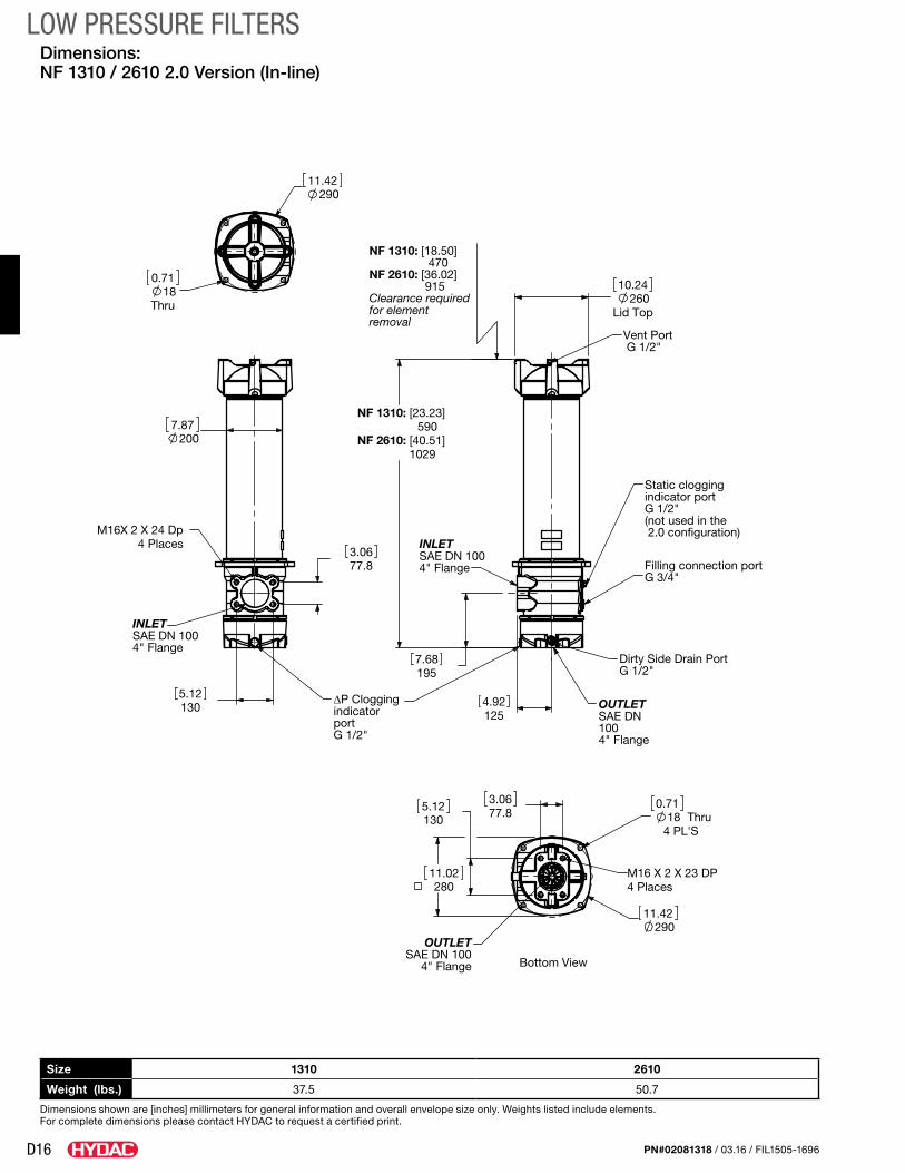
D16 PN#02081318 / 03.16 / FIL1505-1696
LOW PRESSURE FILTERS
Size 1310 2610
Weight (lbs.) 37.5 50.7
Dimensions shown are [inches] millimeters for general information and overall envelope size only. Weights listed include elements. For complete dimensions please contact HYDAC to request a certified print.
Dimensions: NF 1310 / 2610 2.0 Version (In-line)
OUTLETSAE DN 100
4" Flange
1305.12 77.8
3.06
Thru4 PL'S18
11.42290
M16 X 2 X 23 DP
0.71
4 Places
11.02280
INLETSAE DN 1004" Flange
M16X 2 X 24 Dp4 Places
5.12
3.0677.8
130
7.87200
4" Flange100
OUTLET
G 3/4"
Vent Port
SAE DN
Dirty Side Drain PortG 1/2"
G 1/2"
Filling connection port
INLETSAE DN 1004" Flange
Static cloggingindicator portG 1/2"(not used in the 2.0 configuration)
4.92
NF 2610: [40.51] 590
7.68195
NF 1310: [23.23]
1029
125
10.24260
Lid Top
NF 1310: [18.50] 470NF 2610: [36.02] 915Clearance requiredfor element removal
11.42290
0.7118
Thru
Bottom View
∆P Clogging indicatorportG 1/2"

D17PN#02081318 / 03.16 / FIL1505-1696
LOW PRESSURE FILTERS
Size 1350 2650
Weight (lbs.) 39.7 55.2
Dimensions shown are [inches] millimeters for general information and overall envelope size only. Weights listed include elements. For complete dimensions please contact HYDAC to request a certified print.
Mounting Pattern
Bottom View
portG 3/4"
G 1/2"
INLET
∆P Clogging indicator
Dirty side drain port
OUTLET
2.8
10.24
Lid top260
26.89683
NF 2650: 1122 [44.17]
7.6193
71
NF 1350:
7.87200
NF1350 :[18.50]470
NF2650 :[36.02] 915
Clearance required for element removal
Vent portG 1/2"
2509.84
G 1/2"port
∆P Clogging indicator
Dirty side drain portG 3/4"
A
B
M4 Places
C
0.9825
1666.54
1706.69
0.5313.5 Thru
4 Places
Dimensions: NF 1350 / 2650 2.0 Version
Port ConnectionsFlange A B øC M
2” SA-DN 50 77.8 42.9 50 M12 x 1.79 x 19 DP
2 1/2” SAE-DN 65 88.9 50.8 65 M12 x 1.79 x 19 DP
3” SAE-DN 80 106.4 62.9 75 M16 x 2.0 x 24 DP
4” SA-DN 100 130.2 77.8 100 M16 x 2.0 thru
D18 PN#02081318 / 03.16 / FIL1505-1696
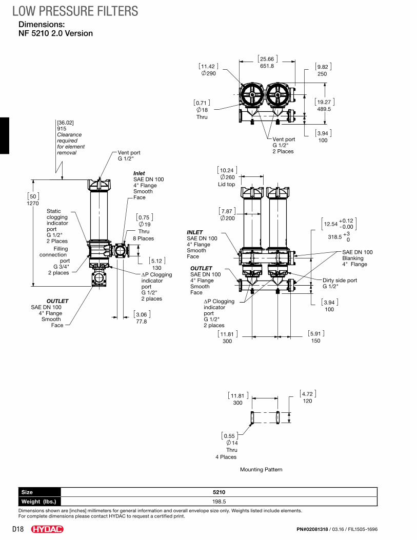
LOW PRESSURE FILTERS
Size 5210
Weight (lbs.) 198.5
Dimensions shown are [inches] millimeters for general information and overall envelope size only. Weights listed include elements. For complete dimensions please contact HYDAC to request a certified print.
Dimensions: NF 5210 2.0 Version
19.27489.5
12.54+-0.120.00
318.5 + 30
Mounting Pattern
30011.81
120 4.72
0.5514
Thru4 Places
Vent portG 1/2"2 Places
9.82 250
1003.94
29011.42
18Thru
0.71
25.66651.8
Smooth 4" FlangeSAE DN 100Inlet
Static
2 placesG 1/2"portindicator
P Clogging
Filling
Face
G 1/2"2 Places
connection port
G 3/4"
cloggingindicatorport
Vent portG 1/2"
2 places ∆
OUTLETSAE DN 100
4" FlangeSmooth
Face 77.8
3.06
1305.12
50 1270
0.7519
Thru8 Places
[36.02]915Clearance required for element removal
portG 1/2"2 places
Face
∆P Clogging indicator
INLETSAE DN 1004" FlangeSmooth
G 1/2"
4" Flange
Dirty side port
BlankingSAE DN 100
OUTLETSAE DN 1004" FlangeSmoothFace
10.24
Lid top260
300 11.81 5.91
150
2007.87
3.94100

D19PN#02081318 / 03.16 / FIL1505-1696
LOW PRESSURE FILTERS
Size 7810
Weight (lbs.) 275.6
Dimensions shown are [inches] millimeters for general information and overall envelope size only. Weights listed include elements. For complete dimensions please contact HYDAC to request a certified print.
Dimensions: NF 7810 2.0 Version
19.27489.5
4" Flange
FaceSmooth
Smooth
SAE DN 100OUTLET
Face
4" FlangeSAE DN 100
INLET
∆P Clogging indicatorportG 1/2"3 places
Dirty sidedrain portG 1/2"3 Places
7.87200
Lid top260
10.24
17.72450
+ 0.120
-0.00
319.5
0.00
29.53
+
750
3.94100
12.58
35.06890.5
Vent portG 1/2"3 Places
1505.91
0.7118
Thru
300
29011.42
9.84250
3.94100
11.81
35.04890
3 Places
Face
Filling connection
port
3 placesG 1/2"portindicator
P Clogging
G 3/4"
G 1/2"
INLETSAE DN 1004" Flange
Static
Smooth
cloggingindicatorport
Vent portG 1/2"
3 places∆
OUTLETSAE DN 100
4" FlangeSmooth
Face 77.83.06
1305.12
50.00 1270
0.7519
Thru8 Places
[36.02]915Clearance required for element removal
Mounting Pattern
348.5
13.72
30011.81
4.72120
0.5514
6 Places

D20 PN#02081318 / 03.16 / FIL1505-1696
LOW PRESSURE FILTERS
Size 10410
Weight (lbs.) 397
Dimensions shown are [inches] millimeters for general information and overall envelope size only. Weights listed include elements. For complete dimensions please contact HYDAC to request a certified print.
Dimensions: NF 10410 2.0 Version
12.54+-0.120.00
318.5+ 30
1003.94
9.84250
19.27489.5
flangesBlanking4" SAE DN
drain portG 1/2"4 PlacesG 1/2"
4 places
Dirty side∆P Clogging indicatorport
OUTLETSAE DN 4"Flange smooth face
5.91
260 10.24
2007.87
150
3.94100
Vent portG 1/2"4 Places
Typ.
11.81
300 5.91 150
29011.42
180.71
49.28
1251.8
smooth face
INLETSAE DN 4"
Flange
Mounting Pattern
300
Thru
11.81
300 11.81
4.73120
8 Places
0.5514
11.81300
4 Places
Face
Filling connection
port
4 placesG 1/2"portindicator
P Clogging G 3/4"
G 1/2"
INLETSAE DN 1004" Flange
Static Smooth
cloggingindicatorport
Vent portG 1/2"
4 places ∆
OUTLETSAE DN 100
4" FlangeSmooth
Face 77.8
3.06
1305.12
50 1270
0.7519
Thru8 Places
[36.02]915Clearance required for element removal

D21PN#02081318 / 03.16 / FIL1505-1696
LOW PRESSURE FILTERS
Size 5210DC7XX2.0/A EM-VKD
Weight (lbs.) 485
Dimensions shown are [inches] millimeters for general information and overall envelope size only. Weights listed include elements. For complete dimensions please contact HYDAC to request a certified print.
Dimensions: NF 5210DC7XX2.0/A EM-VKD (Modular Parallel High Flow)
15.55395
55.171401
61.41
1559.7
Drain
300 lb flange
OUTLET
(Option)
INLET
300 lb flange
manifold
6" ANSI CS
6" ANSI CS
∆ P Clogging indicatorport G 1/2"2 places
1229.7 48.41
656.3 25.84
6.25
158.7
Mounting Pattern
Manual ventvalves Option
G 1/2" ports2 places
30011.81
761.829.99
5.91150
[36.02]915Clearance requiredfor element removal
M16 X 2ThreadedTyp
38.1 1.5
4
13.31
101.6
338.1
38.1 1.5
11.81300
(not used in 2.0 version)clogging indicator G 1/2"
3 places
Connection for static
Filling connection G 3/4"3 places
200
26.67 677.4
7.87
12.8325
10.24260
Lid top

D22 PN#02081318 / 03.16 / FIL1505-1696
LOW PRESSURE FILTERS
Size 7810DC7XX2.0/C EM-VKD
Weight (lbs.) 520
Dimensions shown are [inches] millimeters for general information and overall envelope size only. Weights listed include element. For complete dimensions please contact HYDAC to request a certified print.
Dimensions NF 7810DC7XX2.0/A EM-VKD (Modular Parallel High Flow)
55.171401
61.421560
Drain
OUTLET6" ANSI CS
(Option)manifold
300 lb flange
6" ANSI CS300 lb flange
INLET
∆P Clogging indicatorport G 1/2"3 places
15.55395
2.1 53.2
1229.748.41
6.25158.8
M16 X 2ThreadedTyp
30011.81
38.1 1.5
4101.6
300
25.12638.1
11.81
1.538.1
[36.02]915Clearance requiredfor element removal
1505.91
30011.81
30011.81
39.881012.9
3 places(not used in 2.0 version)
clogging indicator G 1/2"Connection for static
Filling connection G 3/4"3 places
7.87200
677.4
26.67
12.8
325
10.24260
Lid top
Mounting Pattern
Manual ventvalves OptionG 1/2" ports3 places

D23PN#02081318 / 03.16 / FIL1505-1696
LOW PRESSURE FILTERSSizing InformationTotal pressure loss through the filter is as follows:
Assembly ∆P = Housing ∆P + Element ∆P
Housing Curve:
Pressure loss through housing is as follows:
Housing ∆P = Housing Curve ∆P x Actual Specific Gravity
0.86
Adjustments must be made for viscosity & specific gravity of the fluid to be used! (see “Sizing HYDAC Filter Assemblies” in Section B - Overview)
0 100 200 300 400 500
0
0.2
0.4
0.8
0.6
0
2
4
6
10
8
0 20 40 60 80 120 140 100
NF 330/500/750 HOUSINGQ in l/min
Q in gpm
0 400 800 1200 1600 2000
0
0.1
0.2
0.3
0
1.0
2.0
3.0
4.0
0 100 200 300 400 500
NF 1310-2650 HOUSINGQ in l/min
Q in gpm
NF 5210 HOUSINGQ in l/min
Q in gpm
0
0.05
0.1
0.15
0.2 0 400 800 1200 1600 2000
0
1.0
2.0
3.0
0 100 200 300 400 500
NF 7810 HOUSINGQ in l/min
Q in gpm
NF 10410 HOUSINGQ in l/min
Q in gpm
0
0.04
0.08
0.12
0.16
0 400 800 1200 1600 2000
0
0.5
1.0
1.5
2.0
2.5
0 100 200 300 400 5000
0.04
0.08
0.12
0 400 800 1200 1600 2000
0
0.4
0.8
1.2
1.6
2.0
0 100 200 300 400 500
NF 5210DC7 HOUSINGQ in l/min
Q in gpm
NF 7810DC7 HOUSINGQ in l/min
Q in gpm0
0
5.0
10.0
15.0
20.0
25.0
0
0.3
0.9
0.6
1.2
1.5
1.8
250 500 750 1000 1250 1500
0 1000 2000 3000 4000 60005000
00
5.0
10.0
0
0.3
0.6
0.9
250 500 750 1000 1250 1500
0 1000 2000 3000 4000 5000 6000
D24 PN#02081318 / 03.16 / FIL1505-1696
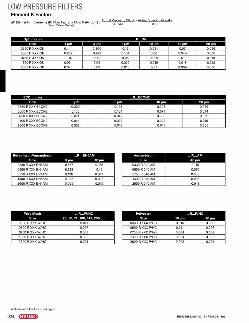
LOW PRESSURE FILTERSElement K Factors
∆P Elements = Elements (K) Flow Factor x Flow Rate (gpm) x Actual Viscosity (SUS) x Actual Specific Gravity
(From Tables Below) 141 SUS 0.86
Wire Mesh …R…W/HC Size 25, 50, 74, 100, 149, 200 µm
0330 R XXX W/HC 0.0110500 R XXX W/HC 0.0070750 R XXX W/HC 0.0031300 R XXX W/HC 0.0022600 R XXX W/HC 0.001
Polyester ...R...P/HCSize 10 μm 20 μm
0330 R XXX P/HC 0.016 0.0080500 R XXX P/HC 0.011 0.0050750 R XXX P/HC 0.004 0.0021300 R XXX P/HC 0.004 0.0022600 R XXX P/HC 0.002 0.001
Betamicron/Aquamicron …R…BN4AMSize 3 µm 10 µm
0330 R XXX BN4AM 0.477 0.1650500 R XXX BN4AM 0.313 0.110750 R XXX BN4AM 0.126 0.0441300 R XXX BN4AM 0.088 0.0332600 R XXX BN4AM 0.055 0.016
Aquamicron …R…AMSize 40 µm
0330 R 040 AM 0.1150500 R 040 AM 0.0760750 R 040 AM 0.0301300 R 040 AM 0.0262600 R 040 AM 0.013
Optimicron …R…ON Size 1 µm 3 µm 5 µm 10 µm 15 µm 20 µm
0330 R XXX ON 0.444 0.204 0.15 0.081 0.07 0.0560500 R XXX ON 0.289 0.143 0.104 0.06 0.046 0.0380750 R XXX ON 0.116 0.061 0.05 0.029 0.019 0.0181300 R XXX ON 0.094 0.04 0.032 0.019 0.018 0.0122600 R XXX ON 0.046 0.02 0.016 0.01 0.009 0.006
ECOmicron ...R...ECON2Size 3 μm 5 μm 10 μm 20 μm
0330 R XXX ECON2 0.230 0.148 0.093 0.0660500 R XXX ECON2 0.165 0.104 0.071 0.0440750 R XXX ECON2 0.071 0.049 0.033 0.0221300 R XXX ECON2 0.044 0.033 0.022 0.0162600 R XXX ECON2 0.022 0.016 0.011 0.005
All Element K Factors in psi / gpm.

D25PN#02081318 / 03.16 / FIL1505-1696
LOW PRESSURE FILTERSNotes