low power control systems for microbial fuel cell … power control systems for microbial fuel cell...
TRANSCRIPT
Low Power Control Systems for Microbial Fuel Cell Batteries
Robert Tyce*, Kenneth Critz*, Jeffrey W. Book**, and Leonard Tender**
*University of Rhode Island, Department of Ocean Engineering, Narragansett, RI 02882 USA **US Naval Research Laboratory, Stennis Space Center, MS and Washington, D.C.
Abstract- The URI Ocean Engineering Department has been working with the US Naval Research Laboratory to develop and test microbial fuel cell battery systems for low power seafloor applications of extended duration. These low power fuel cells utilize graphite electrodes in anoxic sediment coupled to bottle brush graphite electrodes in the water column to make up a battery system. These battery systems typically produce power on the order of 10-50 milli-watts per square meter of electrode area, or as much as ten times more if sediment electrode pore water can be exchanged by means of a pump. As part of this program, testing of these microbial fuel cell batteries has been conducted in the Potomac River Washington D.C., Narragansett Bay Rhode Island, Tuckerton New Jersey, and Monterey Bay California. For these tests it has been necessary to develop long term, low power control and monitoring systems to manage the batteries operation and to record their performance without consuming a significant portion of the meager power produced.
This paper details the development and testing of these low power monitoring systems and their results. For this project we have developed several related systems. All of the systems utilize Oopic microcontrollers as the core low power computer. The Oopic consumes about 20mA at 5 volts when on and none when off. Its programs are stored on EEPROM, and they start from the beginning each time the Oopic is powered up. Notes from the previous time awake can be stored in the EEPROM below the program. The microcontrollers are turned on by an electronic alarm from an I2C real time alarm clock chip with its own multi year lithium battery. The microcontrollers command the shut off of power as part of their program. The real time clock maintains crystal controlled date and time without using any system power. The clock can be programmed to wake up the system at a specific date and time, or at any of numerous intervals. Once awake, the Oopic can check the date, monitor/control the system status and even operate a low power pump.
Long term measurements over many months can be logged on a micro SD card by means of a serial file management storage chip which uses only 3 ma at 3.3 volts when not writing, and a momentary 40mA to write. When the system is asleep none of the subsystems consumes any power. Programmed to awake once an hour for 20 seconds to monitor the system and record the results on the SD card, the average power consumption can be kept to less than 2 milliwatts. The control system can be woken up, report data, accept commands, or be reprogrammed; all through an RS232 serial cable. The system utilizes an RS232 chip that manufactures +/- 10V RS232 signals from +5V with only a few milliamps of additional power consumption. This chip is capable of communicating over a 100m long cable at 9600 baud. In one instance in Tuckerton New Jersey near a dock, it was possible to continuously cable the control system ashore where a Netburner network based microcontroller was connected. The Netburner was programmed to provide an FTP and Telnet site, allowing remote monitoring and control from across the country over the internet.
I. INTRODUCTION/BACKGROUND
A. Benthic Unattended Generators: It has been known for some years that electricity generated
by Geobacteracea bacteria in marine sediments can be harvested by means of a pair of electrodes; one in the water column and the other buried in the seafloor [1]. The University of Rhode Island’s Department of Ocean Engineering (URI) has been assisting the US Naval Research Laboratory (NRL) in developing practical units employing this process, with the promise of long term power for remote low power instruments. NRL’s name for such a unit is Benthic Unattended Generator or BUG. The process has been shown to endure for years but produces only about 10-50 mW of power per m2 of electrode surface area at an optimum voltage below 0.4 volts. The first BUG powered an 18mW meteorological buoy off Tuckerton New Jersey [4]. More recently BUGs have been deployed to help power a 471 mW ADCP mooring in Monterey Bay and a 1-2 Watt SEPTR [5] profiling mooring in Mississippi.
B. Power Conversion:
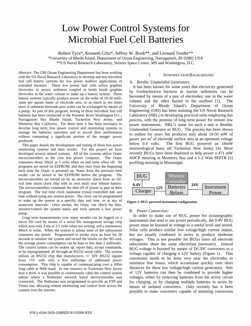
In order to make use of BUG power for oceanographic instruments that tend to use power periodically, the 0.4V BUG power must be boosted in voltage to a useful level and stored. Solar cells produce similar low voltage/high current output, but are usually combined in series to produce moderate voltages. This is not possible for BUGs since all electrode subsystems share the same electrolyte (seawater). Instead BUG voltage is boosted by means of DC/DC converters to a voltage capable of charging a 12V battery (Figure 1). This conversion needs to be done very near the electrodes to minimize line losses, which accumulate quickly over short distances for these low voltage/high current generators. Sets of 12V batteries can then be combined to provide higher voltages, either by removing batteries from the active circuit for charging, or by charging multiple batteries in series by means of isolated converters. Only recently has it been possible to make converters capable of initiating conversion
BUG
Charger
Monitor Controller Batteries Relays
InstrumentPower
12V0.4V 24V
Figure 1: BUG powered instrument configuration
978-1-4244-2620-1/08/$25.00 ©2008 IEEE
Report Documentation Page Form ApprovedOMB No. 0704-0188
Public reporting burden for the collection of information is estimated to average 1 hour per response, including the time for reviewing instructions, searching existing data sources, gathering andmaintaining the data needed, and completing and reviewing the collection of information. Send comments regarding this burden estimate or any other aspect of this collection of information,including suggestions for reducing this burden, to Washington Headquarters Services, Directorate for Information Operations and Reports, 1215 Jefferson Davis Highway, Suite 1204, ArlingtonVA 22202-4302. Respondents should be aware that notwithstanding any other provision of law, no person shall be subject to a penalty for failing to comply with a collection of information if itdoes not display a currently valid OMB control number.
1. REPORT DATE SEP 2008 2. REPORT TYPE
3. DATES COVERED 00-00-2008 to 00-00-2008
4. TITLE AND SUBTITLE Low Power Control Systems for Microbial Fuel Cell Batteries
5a. CONTRACT NUMBER
5b. GRANT NUMBER
5c. PROGRAM ELEMENT NUMBER
6. AUTHOR(S) 5d. PROJECT NUMBER
5e. TASK NUMBER
5f. WORK UNIT NUMBER
7. PERFORMING ORGANIZATION NAME(S) AND ADDRESS(ES) US Naval Research Laboratory,Washington,DC,20375
8. PERFORMING ORGANIZATIONREPORT NUMBER
9. SPONSORING/MONITORING AGENCY NAME(S) AND ADDRESS(ES) 10. SPONSOR/MONITOR’S ACRONYM(S)
11. SPONSOR/MONITOR’S REPORT NUMBER(S)
12. DISTRIBUTION/AVAILABILITY STATEMENT Approved for public release; distribution unlimited
13. SUPPLEMENTARY NOTES See also ADM002176. Presented at the MTS/IEEE Oceans 2008 Conference and Exhibition held in QuebecCity, Canada on 15-18 September 2008. U.S. Government or Federal Rights License.
14. ABSTRACT see report
15. SUBJECT TERMS
16. SECURITY CLASSIFICATION OF: 17. LIMITATION OF ABSTRACT Same as
Report (SAR)
18. NUMBEROF PAGES
7
19a. NAME OFRESPONSIBLE PERSON
a. REPORT unclassified
b. ABSTRACT unclassified
c. THIS PAGE unclassified
Standard Form 298 (Rev. 8-98) Prescribed by ANSI Std Z39-18
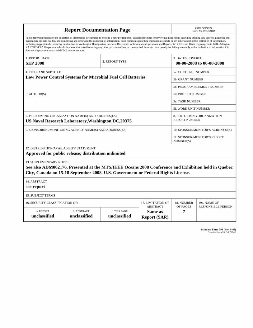
solely from a 0.4V source. BUG converters are isolated current mode converters developed for this project by Northwest Metasystems to charge 12V batteries with an efficiency of 60-70%. Figure 2 shows conversion calibration for one of these converters. Texas Instruments is now offering 5V non-isolated converters working from 0.4V solar cells.
Figure 2: BUG Converter/Charger Calibration
C. Batteries:
For deployments in excess of a year, efficient, low self-discharge rechargeable batteries are needed to store BUG energy. Lithium-Ion batteries have very low self discharge, but have shipping restrictions due to their risk of overheating. For these experiments both 12V Sealed Lead Acid (SLA) and new Hybrid NiMh batteries were used. Both of these have self discharge rates as low as 15% a year with coulombic charge efficiencies reportedly 66-85%. This means a BUG has to supply approximately 3 times the power used by an instrument to support long term operation. For ADCP and SEPTR profilers higher voltage 24V battery packs are required. The ADCP controller system used two small 12V hybrid NiMh battery backs connected in series. The packs are charged inline by a single isolated converter which switches battery packs each day via latching relays. The higher power SEPTR power system utilizes two pairs of 10Ahr sealed lead acid batteries. The pairs are connected in series for operation and isolated for charging. Four BUG converters are combined in parallel with diodes to charge each offline battery which is switched online every other day by means of 4PDT latching relays.
D. Pump Control:
For more efficient power production the BUG sediment electrodes can be enclosed in a caisson and embedded in the seafloor by means of pump suction. If pore water is pumped out periodically, power output can be improved by 10 or more times [3]. Of course this requires very low power pumping to avoid exceeding BUG power production. In our testing DC vane pumps have been used in pressure housings together with bungee accumulators for high power experiments. Small
diaphragm pumps in oil have been used for low power systems. Controlling the flow and suction pressure requires PWM motor speed control from a microcontroller along with differential pressure monitoring.
II. LOW POWER CONTROLLER
A. Oopic-c core processor: Developing BUG power generators has required the
development of long term, low power control and monitoring systems to manage their operation and record their performance without consuming a significant portion of the meager power produced. For systems producing as little as 100mW this represents a challenge. The main tasks of the controller are to 1) measure system voltages, currents and pressures; 2) swap batteries for charging; 3) record results (and report if online) for post mission analysis; and 4) control pump operations when appropriate. Several related system were developed for this project. All of the systems utilize Oopic microcontrollers programmed in Basic as the core low power computer. The Oopic is a very small microcontroller which consumes 16-20mA at 5 volts (80-100mW) when on and none when off. It operates and is programmed via 9600 baud RS232 3 wire serial communication. Its programs are stored on EEPROM, and they start from the beginning each time the Oopic is powered up. Notes from the previous time awake can be stored in the EEPROM below the program. The Oopic has a 4 channel/10bit A/D converter expanded by multiplexer chips to 12 channels for monitoring voltages and currents (via current sensing ICs).
B. Independent Real Time Clock to wake controller:
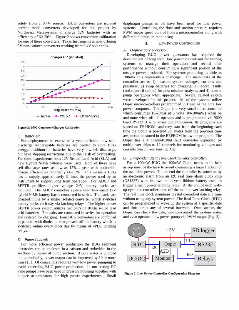
For a 100mW BUG the 100mW Oopic needs to be kept asleep most of the time to avoid consuming a large fraction of the available power. To this end the controller is turned on by an electronic alarm from an I2C real time alarm clock chip (DS1337) with its own multi-year lithium battery used to trigger a main power latching relay. At the end of each wake up cycle the controller turns off the main power latching relay. The real time clock maintains crystal controlled date and time without using any system power. The Real Time Clock (RTC) can be programmed to wake up the system at a specific date and time, or at any of several intervals. Once awake, the Oopic can check the date, monitor/control the system status and even operate a low power pump via PWM output (Fig. 3).
Figure 3: Low Power Controller Configuration Diagram
DC/DC
+3Vbatt
RTC Oopic
Monitor
SD logger
RS232
Relays
I2C TTL
I/O
+5V
A2D

C. SD Card logger and RS232 Subsystems: An independent micro SD card logger (Dosonchip or
uAlfat) is used to store long term measurements over many months by means of serial FAT16 ASCII files. The logger uses only 3-5 mA at 3.3 volts when not writing, and a momentary 40-70mA to write. Power to the SD card logger is controlled by the Oopic.
The controller can be woken up, report data, accept commands, or be reprogrammed; all through an 8 wire 3 x RS232 serial cable (1-Oopic, 2-SD logger, 3-ADCP or AUX device). The main power latching relay can be triggered with a few volts on one of the RS2332 handshake lines. The Oopic does not normally use the handshake lines, requiring only transmit, receive and ground signals for programming (and communication on the same lines). The controller system utilizes an RS232 chip (MAX242) that manufactures +/- 10V RS232 signals from +5V when enabled with only a few milliamps of additional power consumption. This chip is connected to TTL serial lines on the Oopic controller and SD card logger from which it produces RS232 signals capable of driving over 100m of cable at 9600 baud. The Oopic has RS232 signals available directly, but these signals are too weak to drive long cables. The Oopic controls RS232 power to minimize consumption. When the Oopic is asleep the controller subsystems don’t consume any power.
Table 1: SEPTR Once/hour Controller Power Consumption
Device Volts milliAmps on (sec) Avg. (mW) Oopic 5 20 20 0.56 RS232 5 4 20 0.11 Relays 12 150 2 1.0 SD idle 3.3 5 5 .02 SD write 3.3 70 3 .19 TOTAL 1.88
Programmed to awake once an hour for 20 seconds (0.55%)
to monitor a multi-month system deployment and record the results on SD card, the average controller power consumption can be kept to less than 2 mW. Table 1 show the average power consumption for the SEPTR controller with high power Panasonic 4PDT latching relays (133ma to switch). The ADCP controller uses smaller Omron DPDT relays which consume almost 1/10 the relay power, reducing average power consumption to less than 1 mW.
D. Managing charging: The system is designed to monitor and control the charging
of 12 volt batteries from the BUG converter / charger. Charging is a continuous process which is monitored once per hour, saving time, voltage and current measurement values as ASCII files on the SD card and switching which batteries are being charged by means of latching relays.
Figure 4 illustrates a 24V power system for powering an Acoustic Doppler Current Profiler (ADCP) instrument charged by means of a single isolated BUG converter/charger. The controller wakes up each hour to monitor voltage and currents. Each day the controller switches which battery is being charged. The ADCP can be programmed to consume anywhere from 0.1 to 1.2 watts of power within its normal operational specifications for reasonable current measurement accuracies.
Figure 5: ADCP Controller/Batteries/Charger in housing
Figure 5 shows the packaged controller system inside its
cast acrylic pressure housing. The housing contains Oopic controller and latching relay boards, dual 12V battery pack, and single BUG charger. BUG electrodes and ADCP connections are cabled through bulkhead connectors.
For our more power hungry SEPTR environmental profiler system, we designed a 24V power system that did not require isolated chargers. This system has two sets of high capacity 12V Sealed Lead Acid (SLA) batteries switched as pairs between independent charging and operation in series. Figure 6 shows the quad battery charging configuration for the SEPTR BUG controller.
Figure 6: SEPTR 24V quad battery system with 8 chargers
The batteries on charge each have 4 separate BUG systems
and converters contributing charge in parallel via low voltage Schotky diodes and underwater pluggable connectors. In all
- 12V +
- 12V +
- 12V +
- 12V +
Relays 4 Chargers
4 Chargers
+ 24 V
+12V DC/DC
Relay
DC/DC
- + 12 V
- + 12 V
Isolated Charger
+12 V
+24 V
Figure 4: ADCP 24V dual battery system with single isolated charger

8 separate converters charge the two offline batteries. Once a day the batteries are swapped in pairs between online and offline by means of two 4PDT latching relays. Figure 7 shows the insides of the SEPTR BUG controller canister. The top electronics board contains the Oopic controller, Real Time Clock with battery, SD Card logger, RS232 electronics and A/D converter multiplexer. Beneath this board is the main latching relay board with Schotky diodes and current monitor electronics for inputs from the 8 BUG chargers.
Figure 7: Inside of SEPTR quad battery/controller cannister
In this case the chargers are potted units attached directly to the BUG electrode assemblies and cabled to the controller canister. Cable length issues are greatly reduced once the chargers convert the 0.4V BUG voltage to 12V for charging, so an array of BUG units with potted chargers can be installed around a SEPTR instrument without significant line losses.
Figure 8: Eight BUG potted charger units for SEPTR 5 x 10 x 15 cm
Figure 8 shows the 8 encapsulated charger units which are
each about 5cm x 10cm x 15cm. Underwater pluggable connectors on the charger units and isolation diodes on the controller allow the chargers to be connected underwater after
the BUG electrode sets have been buried in the sediment and suspended in the water column.
Figure 9 shows the block diagram for the SEPTR BUG electrodes and charging system. Here sediment graphic plates have been assembled into electrode cubes approximately 30cm on a side. Three of these cubes are combined along with bottle brush shaped water column graphite electrodes for input to each converter.
Figure 9: SEPTR BUG Electrode / charging block diagram
In the foreground of figure 10 is a BUG equipped SEPTR
instrument rigged with trays to carry the BUG electrodes and chargers to the seafloor for deployment. In the background are two normal SEPTR units. SEPTR stands for “Shallow water Environmental Profiler in Trawl-resistant Real-time configuration”. The SEPTR contains an ADCP instrument plus a profiling buoy winched to and from the surface where it communicates ashore via satellite [2].
Figure 10: SEPTR with BUG Electrodes ready for deployment
SEPTR
Brush
4 x 3 Cubes – two sets
Program connector
SEPTR Controller
Battery / Controller
ConverterConverterConverter Converter
Brush Brush Brush

E. Controller programming: The Oopic-c microcontroller used in these systems is
programmed in basic via RS232 serial at 9600 baud. Its program is stored on EEPROM and immediately executed upon power up. At the end of the program the processor turns off power to keep power consumption to a minimum. Coupled with a Real Time Clock with alarm and its own battery, no system power is used by the controller until woken up. To enable reprogramming and system configuration changes, the controller can also be woken up remotely by applying a few volts of power to one of the RS232 handshake lines, which is connected to a parallel wakeup circuit which switches on both the controller and RS232 power.
When woken up the software will first determine if it was awoken by an RTC alarm or remotely. If a remote wakeup, the system will display an RS232 menu and stay awake for a short period awaiting input or reprogramming from the surface. A remote wakeup is indicated if the RTC alarm flag is not set. RS232 power is switched off by the Oopic under menu control.
If the RTC alarm flag is set, the system will proceed with its normal monitor and battery charge management tasks. These include recording time, system and battery voltages and charge/discharge currents on the SD card data logger after enabling logger power. They also include alternating the batteries being charged by switching the state of latching relays. The controller is woken up each hour by the RTC from which it gets the date and time. The controller is programmed to alternate batteries each day. When finished with all tasks, the system shuts down logger power before turning off its own power, which can then only be turned back on by the clock or by the surface RS232 connection. Figure 11 shows the basic functionality of the software in flow chart form.
F. Real Time Monitoring/ control via Internet
In some cases it has been possible to cable the BUG control system ashore and monitor operations in real time. Such was the case for a meteorological buoy first powered by a BUG in Tuckerton New Jersey, off the dock at Rutgers Marine Field Station or RMFS [4]. To enable remote monitoring and
control of the BUG controller, a Netburner 5270 Ethernet capable microcontroller was connected to the internet at RMFS. This system was programmed to provide serial connectivity to the BUG controller over the internet via Telnet. This allows us to connect to the controller from Rhode Island and either log data, or change system parameters via the controller menu when it was awake.
The controller was programmed to wake up every minute for several seconds instead of every hour. To insure no real time data was lost during internet communications failures, the Netburner computer was also programmed to log BUG controller data as serial data files on its own SD card which it was programmed to make available as an FTP site on the internet. Telnet and FTP software examples from Netburner were modified to make them work with our particular application. Figure 12 is a block diagram of the RMFS installation with the Internet-connected Netburner TCP/IP data logger and battery cannister located dockside. The controller/charger enclosure was submerged along with cathode and reference electrodes. The graphite anode electrode cubes were buried in the mud below the dock and connected to the controller.
The Tuckerton system output 6 ASCII strings that were
received real time over the internet to anywhere in the country via telnet. The data streamed out of the charge controller as RS232 at 9600 baud over a 100 meter cable to the Netburner network based microcontroller that broadcast the data via telnet and saved it to an SD card. The charge controller was on for 6 seconds of every minute for which it output 6 ASCII strings and listened for commands to switch batteries. In contrast, the ADCP and SEPTR systems were designed to stand alone and log data to a microSD card within the monitor/ controller.
III. SIMULATED LONG TERM TESTING
A. How to simulate Long Term Deployment: It is a particularly challenging task to simulate deployment
of a long term monitoring instrument in a short period of time. For deployments of a year or more this is a particular challenge. Often this requires significant software modifications which call into question the reliability of such tests. In our case a very simple simulation protocol was
TCP IP / Data Log
ControllerEnclosure
Cathode Float
Ref.
Anode Cubes
12 V Batts
Wake Up Alarm?
Date & Time Menu
Battery Select
SD Logger On Read A/D, Write to SD
SD Logger Off
System Off
No Yes
Figure 11: Oopic Controller Software flow chart
Figure 12: RMFS Dockside Internet data Logging configuration

developed which modifies almost none of the operating software. We call this the “quickflag” protocol.
When woken up by the surface RS232 handshake line, the Oopic controller displays a menu which includes the quickflag option. When turned on, this option sets to “1” a word in the Oopic’s EEPROM memory at the end of its program. The operator then uses the menu to set the present time and date into the RTC, to set the wake up dates into EEPROM memory, to enable RTC alarms and to put the controller to sleep. When awoken by a RTC alarm the controller performs its entire set of monitor and control functions as usual. Just before putting itself to sleep it checks the quickflag word in memory. If not set it goes to sleep. If set it goes to sleep only after resetting the RTC date and time to 15-30 seconds before the next alarm date and time.
This simple change means that the system can skip ahead a month or more in a few seconds, and simulate deployments of a year or more in minutes or hours. Since the controller consumes no power when asleep, this high speed simulation accurately simulates controller power consumption. If BUG charging and instrument power consumption are scaled in accordance, then an accurate simulation of long term deployment results.
For the ADCP controller, a minimum 2 month deployment was anticipated. Figure 13 shows the bottom 12V battery voltage data for a 2 month simulated deployment where no BUG charging was available. The battery voltage declined to 9 volts in just over 2 months. Below 9 volts the controller is unable to toggle its latching relays. The spikes in voltage represent the charged battery switching which occurs each month, except when the month has 31 days, since the battery to charge is determined by whether the day is even or odd. The bottom battery which powers the controller is always the one to get the extra charge.
Figure 13: ADCP controller Bottom Battery long-term testing
Long term testing was also conducted on the SEPTR controller system for simulated periods of over a year. These tests revealed two critical system problems which were remedied as a result of this testing. The first problem resulted from our initial approach to SD card writing. Using serial commands the Oopic opens a file for writing on the SD card
logger with a name corresponding to the date, tells the SD card logger the number of characters to write, then sends the string of characters. During our testing we used a standard time delay between issuing file write commands instead of checking for confirmation. After a month of writing hourly files the time required by the logger to prepare for writing a new file increased enough to result in command errors. Apparently file setup time grows as more files are stored to the SD card. This problem was fixed by having the Oopic wait for command confirmation from the logger after each command.
The second problem only occurred after more than a year of simulated data logging from the SEPTR system. The Oopic uses the RTC date as the file name for data logging. Each new day a new file is created. The logger writes FAT16 files which are limited in number to 512 in each directory. After 1.4 years of logging no new files can be created. The solution to this problem is to have the Oopic create separate directories for each year of deployment.
B. Data Retrieval:
After deployment, data will be found on the SD card which can be removed and inserted directly into a PC SD card reader. Files are named with the date and easily read with WordPad or other simple text file program. Of course, this requires opening the controller cannister to remove the SD card.
For data retrieval both after the deployment and anytime during the deployment or deployment preparation, data can be accessed by means of the 8-pin serial program connector and cable. This connector is wired for 3 separate RS232 connections, with one for programming the ADCP instrument on the ADCP controller version. In both SEPTR and ADCP controller versions the other two RS232 connections are for the Oopic and the SD card Logger. When woken up by means of the cable, the Oopic and logger are available to the surface through the MAX242 dual RS232 chip. By means of HyperTerminal or other serial communication program on the PC one can access the logger directory and files directly, and transfer data without opening the system. Under normal operations the RS232 chip is turned off to save power and the Oopic connects to the logger via TTL serial.
IV. CONCLUSIONS
By combining low power microcontroller, Real Time Clock, SD card logger and latching relay components, it has been possible to develop monitor / controller systems for seafloor microbial fuel cell batteries that consume less than 2 milli-watts average power and can run for years. Connecting these to an internet based microcontroller with FTP and TCP/IP Telnet functionality allows real time monitoring and control when the system can be cabled or wirelessly connected ashore. Realistic long term deployment simulation of these systems can be achieved by automatically advancing the time being kept by the Real Time Clock wakeup system.

ACKNOWLEDGEMENTS
The work presented here was supported by the US Naval Research Laboratory under a grant to the University of Rhode Island. This grant and the work of J.W. Book and L. Tender were supported by the Office of Naval Research as part of the research program “Unattended Sea-bed Power for In-water Operations” under Program Element 0602435N.
REFERENCES
[1] D.R. Bond, D.E. Holmes, L.M. Tender, and D.R. Lovley; “Electrode-Reducing Microorganisms That Harvest Energy from Marine Sediments” Science: Vol. 295, pp. 483-485. 18 January 2002.
[2] J.W. Book, M. Rixen, A. Carta, M. Hulbert, A. Quaid,
E. Coelho, V. Grandi, and L. Gualdesi; “Shallow Water Environmental Profiler in Trawl-resistant Real-time Configuration (SEPTR) Used for Frontal Dynamics Research”, In 2007 – Rapp. Comm. Int. Mer Medit. Vol. 38, pg. 130, CIESM Congress (Istanbul, 2007), CIESM: The Mediterranean Science Commission, Monaco, 2007.
[3] D.C. Flynn; “Engineering a BUG (Benthic Unattended
Generator): Development of a Benthic Microbial Fuel Cell,” University of Rhode Island Master’s Degree Thesis, Dept. of Ocean Engineering, 2007.
[4] L. M. Tender, S. Gray, E. Grooveman, D. Lowy, P.
Kauffman, J. Melhado, R. Tyce, D. Flynn, R. Petrecca and J. Dobarro; “The First Demonstration of a Microbial Fuel Cell as a Viable Power Supply: Powering a Meteorological Buoy.” Journal of Atmospheric and Oceanic Technology: in press 2008.
[5] R. Tyce, F. de Strobel, V. Grandi, and L. Gualdesi;
“Trawl-Safe Profiler Development at SACLANT Centre for Shallow Water Environmental Assessment and Real Time Modeling” Oceans 2000 MTS/IEEE – Where Marine Science and Technology Meet, Conference Proceedings: pp. 99-104. September 2000.