low-nox hydrogen burner
TRANSCRIPT
Pergamon ht. J. Hydrogen Energy Vol. 21, No. 6, pp. 445 449, 1996
Copyright @ 1996 International Association for Hydrogen Energy Elsevier Science Ltd
0360-31!B(%)oo1oM Printed in Great Britain. All rights reserved 036&3199/96 s15.00 -I- om
LOW-NO, HYDROGEN BURNER
A. VAN DER DRIFT, S. L. TJENG, G. J. J. BECKERS and J. BEESTEHEERDE Netherlands Energy Research Foundation (ECN), P.O. Box 1, 1755 ZG Petten, Holland
(Received for publication 22 September 1995)
A&&act--ECN ceramic foam burners, originally designed to bum premixed air/natural gas, prove to be suitable for burning mixtures of H, and CH, up to a H&H, ratio of 70/30 (by volume) at any air ratio (air factor from 0.6 to 1.6) at power densities ranging from 200 to 2000 kW m-‘. No catalyst is used. NO, emissions wm relatively low (5-50 ppm), as compared to a commercially available nozzle mix burner (90-120 ppm) measured at 30% excess air. ECN have developed a new (non-catalytic) burner capable of burning hydrogen-rich fuels with extremely low NO,-emissions: under 5 ppm NO, measured at 30% excess air. Finally both concepts have been combined and a third burner has been made which can bum H&H, mixtures at any comp&tkn with NO,-emissi~ns beIow 15 ppm. This new burner is still under investigation. Copyright @I996 International Association for Hydrogen Energy
1. INTRODUCTION
Most combustion processes use hydrocarbons, usually fossil fuels, as fuel. During combustion these fuels are converted to water and carbon dioxide while ‘releasing heat. During this reaction, however, a secondary reaction often takes place between oxygen and nitrogen from the air. The products (nitrogen oxides: NO,), play an im- portant role in the acidification of the environment. Much research has been done in order to reduce the emission of NO, but only recently has it been realised that CO,, the inevitable product of fossil fuel combustion, can also
methane
0 20 40 00
Exces8 Alr [K)
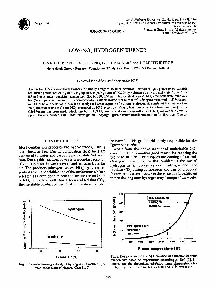
Fig. 1. Laminar burning velocig of hydrogen and methane (the main constituent of Natural Gas) [1, 23.
be harmful. This gas is held partly responsible for the “greenhouse-effect”.
Apart from the above mentioned undesirable CO, emission, there is another good reason for reducing the use of fossil fuels. The supplies are coming to an end. One possible solution to this problem is the use of hydrogen as an energy carrier. Hydrogen does not produce CO, during combustion and can be produced from water by electrolysis. For these reasons it is expected that in the long term hydrogen may “conquer” the world.
IWO 1000 2wo 2100 2200 2300 24olI
Flame temperature [K]
Fig. 2. Rough estimation of NO, emission as a,fun&%n of tkme temperature based on experiments to Rd. 533. In- dicated are the theoretical adiabatic Aatne tcmpe;ratures for
hydrogen and methane for both 10 and 30% excess air.
445

446 A. VAN DER DRIFT et al.
Pressure tap
Suction pyrometer -
Pressure tap
Ceramic burner plate
Peephole for IR pyrometer
Heat exchanger
t Flue gas
Fig. 3. Test facility at ECN for ceramic foam burners, H burner and combined concept used for the measurement of flue gas composition.
In the intermediate phase of this scenario hydrogen is The combustion of hydrogen instead of fossil fuels, mixed with natural gas. In anticipation of this develop- however, is associated with some major difficulties. For ment ECN started several projects concerning hydrogen example, hydrogen will burn much faster than, e.g., production. H, recovery and separation with ceramic natural gas. The difference is shown in Fig. 1 with the membranes and application of hydrogen. One of these laminar burning velocity of hydrogen together with that “application projects” concerns the development of a of methane, being the main constituent of natural gas [l, low-NO, burner for the combustion of pure hydrogen 21. From this it is clear that natural gas burners will not and hydrogen/natural gas mixtures. usually be suitable for burning hydrogen safely.
LOW-NO, HYDROGEN BlJRNER 441
Apart from the high reaction speed, the flame tempera- ture for hydrogen combustion is also high. As NO,- production strongly depends on temperature it is ex- pected that NO, emission from hydrogen flames will be greater than that from methane flames. Figure 2 illustrates the effect of flame temperature on NO, emission in practical situations [3]. Flame temperatures of methane and hydrogen are indicated.
Since most conventional (natural gas) burners will not be suitable for hydrogen and hydrogen/natural gas mix- tures, new burners have to be developed in order to (1) prevent problems associated with the high reactivity of hydrogen and (2) reduce NO, emissions caused by the high flame temperature.
2. EXPERIMENTAL SET-UP
Measurements with all ECN burners were performed in a standard test facility (Fig. 3) which resembles a domestic central heating boiler. The ceramic foam burner plate measures 0.013 m2, both the H burner and the combined concept burner measure 0.01 m2. Experiments were carried out with hydrogen and methane. Flue gas samples were continuously taken and subsequently dried in order to measure NO,, O,, CO,, CO, H, and C,H,. Radiation measurements were performed with a radiometer in a separate test using an open test rig without a heat exchanger.
Tests with a commerically available nozzle mix burner were performed for comparison purposes in a slightly adapted test facility due to the extended flame. The burner was operated at 20 kW.
3. RESULTS AND DISCUSSION
Ceramic foam burner
At ECN (Netherlands Energy Research Foundation) surface burners have been developed on the basis of highly porous ceramic foam material [4]. Premixed fuel gas (hydrogen/natural gas mixtures) and air are supplied to the burner which can operate in a radiant as well as a “blue flame” mode. These burners show very low NO, emissions because gas and air are premixed and conse- quently peak temperatures are avoided. Furthermore, when operated in the radiant mode an extra effect occurs: part of the combustion energy is radiated to the sur- roundings resulting in low flame temperatures and thus even lower NO, emissions.
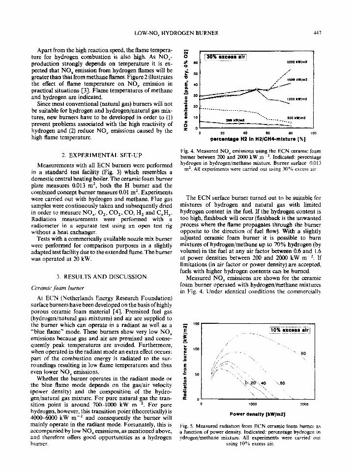
Whether the burner operates in the radiant mode or the blue flame mode depends on the gas/air velocity (power density) and the composition of the hydro- gen/natural gas mixture. For pure natural gas the tran- sition point is around 7O&lOOO kW m-2. For pure hydrogen, however, this transition point (theoretically) is 4000-6000 kW me2 and consequently the burner will mainly operate in the radiant mode. Fortunately, this is accompanied by low NO, emissions, as mentioned above, and therefore offers good opportunities as a hydrogen burner.
percentage H2 in Hi/CHGmixture [%I
Fig. 4. Measured NO, emissions using the ECN ceramic foam burner between 200 and 2ooO kW m-‘. Indicated: percentage hydrogen in hydrogen/methane mixture. Burner surface: 0.013
m2. All experiments were carried out using 30% excess air
The ECN surface burner turned out to be suitable for mixtures of hydrogen and natural gas with limited hydrogen content in the fuel. If the hydrogen content is too high, flashback will occur (flashback is the unwanted process where the flame propagates through the burner opposite to the direction of fuel flow). With a slightly adjusted ceramic foam burner it is possible to burn mixtures of hydrogen/methane up to 70% hydrogen (by volume) in the fuel at any air factor between 0.6 and 1.6 at power densities between 200 and 2000 kW me-‘. If limitations (in air factor or power density) are accepted. fuels with higher hydrogen contents can be burned.
Measured NO, emissions are shown for the ceramic foam burner operated with hydrogen/m&bane mixtures in Fig. 4. Under identical conditions the commercially
0 1000
Power density [kW/m2]
2000
Fig. 5. Measured radiation from ECN ceramic foam burner as a function of power density. Indicated: percentage hydrogen in ydrogen/methane mixture. All experiments were carried out
using 10% excess air,
448 A. VAN DER DRIFT et al.
2300 I
2200
2100
2000
12OQ
1800
1700 0 1000 2000
Power density [kW/mP]
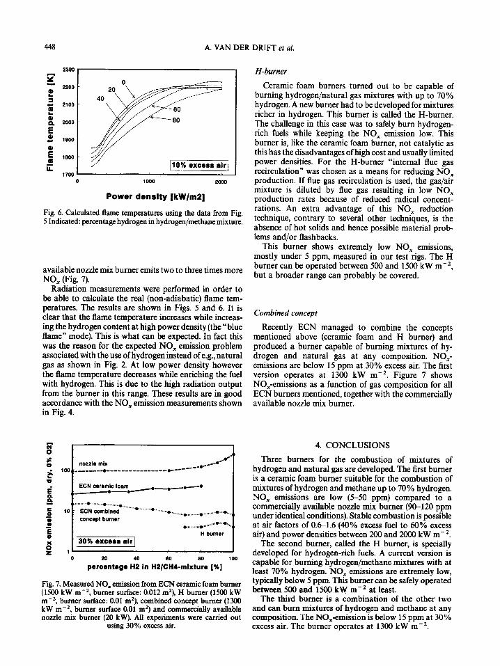
Fig. 6. Calculated flame temperatures using the data from Fig. 5 Indicated: percentage hydrogen in hydrogen/methane mixture.
available nozzle mix burner emits two to three times more NO, (Fig. 7).
Radiation measurements were performed in order to be able to calculate the real (non-adiabatic) flame tem- peratures. The results are shown in Figs. 5 and 6. It is clear that the flame temperature increases while increas- ing the hydrogen content at high power density (the “blue flame” mode). This is what can be expected. In fact this was the reason for the expected NO, emission problem associated with the use of hydrogen instead of e.g., natural gas as shown in Fig. 2. At low power density however the flame temperature decreases while enriching the fuel with hydrogen. This is due to the high radiation output from the burner in this range. These results are in good accordance with the NO, emission measurements shown in Fig. 4.
Fig. 7. Measured NO, emission from ECN ceramic foam burner (1500 kW m -‘, burner surface: 0.012 m2), H burner (1500 kW m-‘, burner surface: 0.01 rn’), combined concept burner (1300 kW m-‘, burner surface 0.01 m’) and commercially available nozzle mix burner (20 kW). All experiments were carried out
using 30% excess air.
H-burner
Ceramic foam burners turned out to be capable of burning hydrogen/natural gas mixtures with up to 70% hydrogen. A new burner had to be developed for mixtures richer in hydrogen. This burner is called the H-burner. The challenge in this case was to safely burn hydrogen- rich fuels while keeping the NO, emission low. This burner is, like the ceramic foam burner, not catalytic as this has the disadvantages of high cost and usually limited power densities. For the H-burner “internal flue gas recirculation” was chosen as a means for reducing NO, production. If flue gas recirculation is used, the gas/air mixture is diluted by flue gas resulting in low NO, production rates because of reduced radical concent- rations. An extra advantage of this NO, reduction technique, contrary to several other techniques, is the absence of hot solids and hence possible material prob- lems and/or flashbacks.
This burner shows extremely low NO, emissions, mostly under 5 ppm, measured in our test rigs. The H burner can be operated between 500 and 1500 kW m-‘, but a broader range can probably be covered.
Combined concept
Recently ECN managed to combine the concepts mentioned above (ceramic foam and H burner) and produced a burner capable of burning mixtures of hy- drogen and natural gas at any composition. NO,- emissions are below 15 ppm at 30% excess air. The first version operates at 1300 kW m-‘. Figure 7 shows NO,-emissions as a function of gas composition for all ECN burners mentioned, together with the commercially available nozzle mix burner.
4. CONCLUSIONS
Three burners for the combustion of mixtures of hydrogen and natural gas are developed. The first burner is a ceramic foam burner suitable for the combustion of mixtures of hydrogen and methane up to 70% hydrogen. NO, emissions are low (5-50 ppm) compared to a commercially available nozzle mix burner (90-120 ppm under identical conditions). Stable combustion is possible at air factors of 0.61.6 (40% excess fuel to 60% excess air) and power densities between 200 and 2000 kW m-‘.
The second burner, called the H burner, is specially developed for hydrogen-rich fuels. A current version is capable for burning hydrogen/methane mixtures with at least 70% hydrogen. NO, emissions are extremely low, typically below 5 ppm. This burner can be safely operated between 500 and 1500 kW mm2 at least.
The third burner is a combination of the other two and can bum mixtures of hydrogen and methane at any composition. The NO,emission is below 15 ppm at 30% excess air. The burner operates at 1300 kW m-‘.
LOW-NO, HYDROGEN BURNER 449
5. REFERENCES 3. M. B. M. Visser and H. B. Levinsky, Premixed combustion in gas fired equipment, 16. Deutscher Flammentag, VDI Beri- chte 1090, Claustal, Germany, 14-15 September, pp. 139-146 (1993).
1. G. W. Koroll, R. K. Kumar and E. M. Bowles, Burning 4. J. Beesteheerde, G. J. J. Beckers, P. R. Visser, S. L. Tjeng and velocities of hydrogen-air mixtures. Cornbust. Flame 94, A. van der Drift, Low NO, ceramic foam burner for domestic 33+340 (1993). and industrial utilisation. International gas research confer-
2. B. Lewis and G. von Elbe, Combustion, Flames and Explosions ence, Gas Research Institute. Vol. IV, 16-19 November. qf Guses, 3rd edn. Academic Press, New York (1987). Orlando. Florida, U.S.A., pp. 286295 11992).