low flow cimv overview - skoflo flow cimv specification.pdf · low flow cimv chemical injection...
TRANSCRIPT

Low Flow CIMV Chemical Injection Metering Valves
L200-R, L200-S, L201-R, L201-S
SkoFlo L200 series are the industry leading subsea chemical injection metering valves. CIMVs are used to inject low dosage chemicals such as wax, scale, corrosion, and asphaltene inhibitors and demulsifiers.
The L series CIMVs bring together the following advantages:
Pressure independence: Flow delivery rates are unaffected by fluctuations in supply or well pressure.
SkoFlo’s proprietary pressure-balanced piston maintains constant flow while using no electric power.
Advanced ceramics eliminate filming.
SkoFlo’s highly accurate Positive Displacement Flow Meter (PDFM) with accurate volumetric flow measurement.
Self-calibrating: The capability to change chemicals easily as project requirements change.
Three methods of flow measurement for built-in redundancy.
10 LOW FLOW CIMV | Over view SUBSEA SYSTEMS 11
LF
SkoFlo CIMV technology delivers precise and stable flow, regardless of fluctuations in supply or well pressure.
Over
view
LOW FLOW CIMV
For Receptacles see page 34
FLOW
(%
FUL
L SC
ALE)
VALVE PERFORMANCE CURVE
PRESSURE (BAR)
Pressure Independence +/- 5% of reading
10%
50%
100%
5%
75%
100
200
300
400
500
PRESSURE (BAR)
FLO
W (%
FU
LL S
CA
LE)
60
+/- 5% OF Rated Full ScaleFlow Delivery Accuracy
31
Model No.
Connection Min Flow (GPD)
Min Flow (LPH)
Max Flow (GPD)
Max Flow (LPH)
Turn Down Ratio
L200-R ROV Mate 2 .32 500 78.9 250 L200-S Stab Mate 2 .32 500 78.9 250 L201-R ROV Mate 10 1.6 1,200 189.0 119 L201-S Stab Mate 10 1.6 1,200 189.0 119

Pressure Sensors
Four pressure sensors calculate flow rate and are used for diagnostic purposes. See Benefits on page 15
P3 P4P2P1
12 LOW FLOW CIMV | System Architecture and Key Features SUBSEA SYSTEMS 13
LF
P2P1
P3 OUTLETCOUPLERCHECKVALVE
SENSORMeasures oulet pressure
SENSOROrifice inlet pressure
SENSOROrifice outlet pressure
POSITIVE DISPLACEMENTFLOW METER
VARIABLE ORIFICE
P4
SENSOR Measures inlet pressure
INLET COUPLER CATCHSCREEN
Variable OrificeSkoFlo patented variable orifice ensures a higher turndown ratio with maximum debris tolerance. See Benefits on page 15
Pressure-Balanced PistonSkoFlo patented Pressure-Balanced Piston ensures constant flow regardless of any pressure changes. It effectively allows debris to pass through the system. The pressure-balanced piston device is fail as-is without drift.See Benefits on page 15
Key
Fea
ture
sLOW FLOW CIMV
Positive Displacement Flow MeterPositive Displacement Flow Meter (PDFM) is a device used to measure chemical flow rates that provides accurate volumetric flow measurements. See Benefits on page 14
M
PRESSURE BALANCED PISTON
SUBSEA SYSTEMS 1514 LOW FLOW CIMV | Benefits
LF
Bene
fitsLOW FLOW CIMV
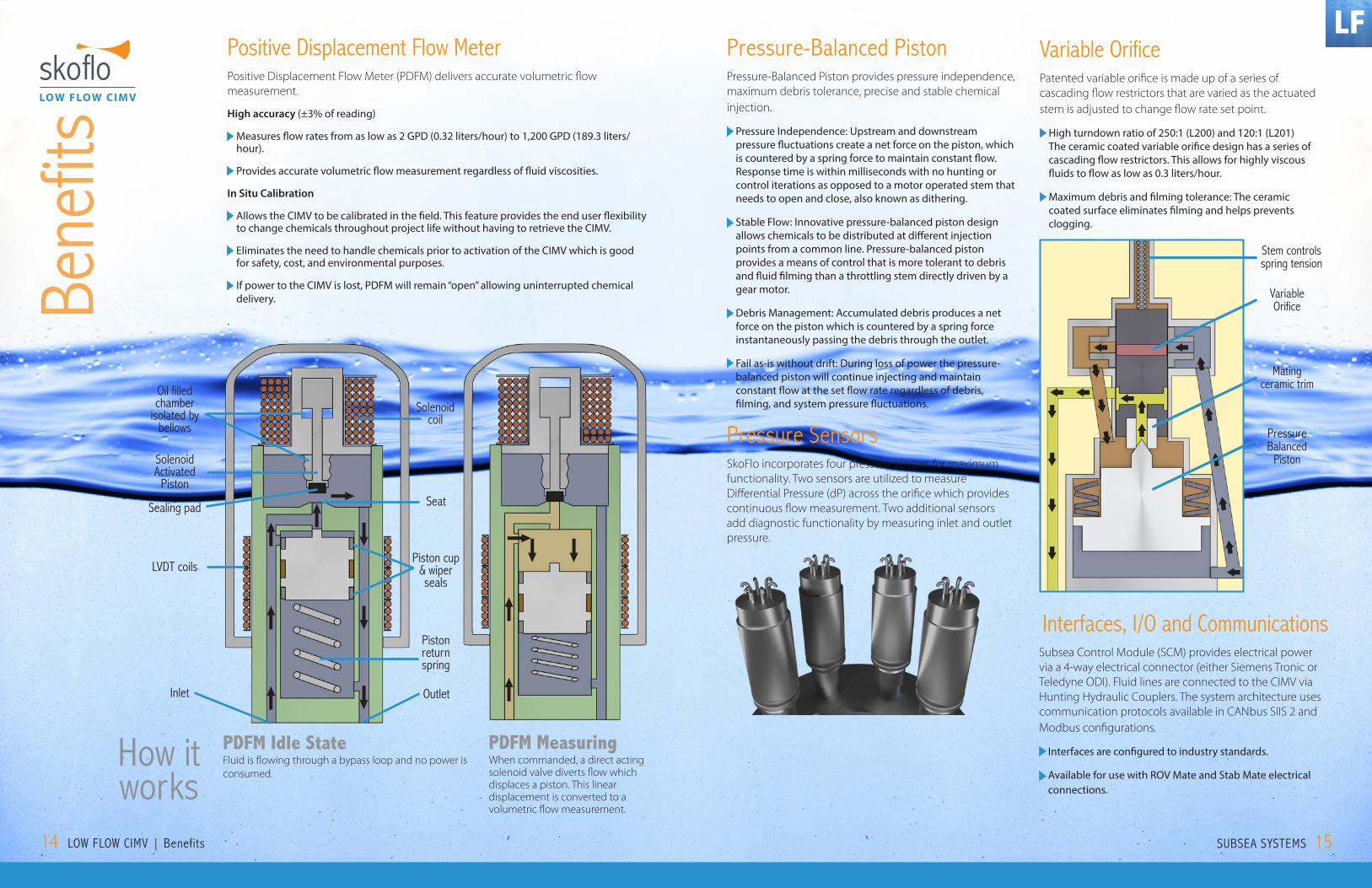
PDFM Idle StateFluid is flowing through a bypass loop and no power is consumed.
PDFM Measuring When commanded, a direct acting solenoid valve diverts flow which displaces a piston. This linear displacement is converted to a volumetric flow measurement.
How it works
Positive Displacement Flow MeterPositive Displacement Flow Meter (PDFM) delivers accurate volumetric flow measurement.
High accuracy (±3% of reading)
Measures flow rates from as low as 2 GPD (0.32 liters/hour) to 1,200 GPD (189.3 liters/hour).
Provides accurate volumetric flow measurement regardless of fluid viscosities.
In Situ Calibration
Allows the CIMV to be calibrated in the field. This feature provides the end user flexibility to change chemicals throughout project life without having to retrieve the CIMV.
Eliminates the need to handle chemicals prior to activation of the CIMV which is good for safety, cost, and environmental purposes.
If power to the CIMV is lost, PDFM will remain “open” allowing uninterrupted chemical delivery.
.
SolenoidActivated
Piston
Piston cup& wiper seals
Piston return spring
Oil filled chamber
isolated by bellows
Sealing pad
LVDT coils
Inlet
Solenoidcoil
Seat
Pressure-Balanced PistonPressure-Balanced Piston provides pressure independence, maximum debris tolerance, precise and stable chemical injection.
Pressure Independence: Upstream and downstream pressure fluctuations create a net force on the piston, which is countered by a spring force to maintain constant flow. Response time is within milliseconds with no hunting or control iterations as opposed to a motor operated stem that needs to open and close, also known as dithering.
Stable Flow: Innovative pressure-balanced piston design allows chemicals to be distributed at different injection points from a common line. Pressure-balanced piston provides a means of control that is more tolerant to debris and fluid filming than a throttling stem directly driven by a gear motor.
Debris Management: Accumulated debris produces a net force on the piston which is countered by a spring force instantaneously passing the debris through the outlet.
Fail as-is without drift: During loss of power the pressure-balanced piston will continue injecting and maintain constant flow at the set flow rate regardless of debris, filming, and system pressure fluctuations.
Pressure SensorsSkoFlo incorporates four pressure sensors for maximum functionality. Two sensors are utilized to measure Differential Pressure (dP) across the orifice which provides continuous flow measurement. Two additional sensors add diagnostic functionality by measuring inlet and outlet pressure.
Stem controls spring tension
Mating ceramic trim
VariableOrifice
Pressure Balanced
Piston
Outlet
Interfaces, I/O and CommunicationsSubsea Control Module (SCM) provides electrical power via a 4-way electrical connector (either Siemens Tronic or Teledyne ODI). Fluid lines are connected to the CIMV via Hunting Hydraulic Couplers. The system architecture uses communication protocols available in CANbus SIIS 2 and Modbus configurations.
Interfaces are configured to industry standards.
Available for use with ROV Mate and Stab Mate electrical connections.
Variable Orifice Patented variable orifice is made up of a series of cascading flow restrictors that are varied as the actuated stem is adjusted to change flow rate set point.
High turndown ratio of 250:1 (L200) and 120:1 (L201) The ceramic coated variable orifice design has a series of cascading flow restrictors. This allows for highly viscous fluids to flow as low as 0.3 liters/hour.
Maximum debris and filming tolerance: The ceramic coated surface eliminates filming and helps prevents clogging.

Flow Measurement Range Flow Range
1 2 to 500 gpd (0.3 to 79 liters/hr)
2 10 to 1200 gpd (1.6 to 189 liters/hr)
Flow Measurement
Method Description Flow by PDFM Positive displacement flowmeter integral to the valve. Flow by DP Flow calculation from differential pressure sensing across a precision orifice. Flow by Stem Flow inference comparing current stem position to a calibration table.
Pressure Independence Maintains set flow rate despite debris and upstream or downstream pressure fluctuations. See attached graph (Actual flow measurement reading per 1000psi DP change)
Loss of power/communication Fail as is without drift. In event of loss of power or communication, valve will continue to control set flow rate.
Minimum Differential Pressure 250 psi (17 bar) required to regulate flow independent of pressure. (25% MEG in water at room temperature. For fluid viscosities 3-100cP, see equation above)
Design Ratings Design Standards ISO 13628-6 (API 17F), ISO 13628-8 (API 17H), ASME B31.3, ASME BPVC Section VIIII
Design Life 25 years
Working Pressure Rating 10,000 psig (690 barg)
Water Depth Rating 10,000 ft (3,048 m)
Temperature Rating Operating: 38°F to +100°F (3.3°C to 37.8°C), (0°F to +158°F with reduced performance)
Storage: 0°F to +158°F (-18°C to 70°C)
Viscosity 0.5 - 100 cp
Debris tolerance SAE AS4059 Class 12B-F
Materials (chemically wetted)
Valve Body Nitronic 50HS
Metallic components Nitronic 50HS, 316/316L SS, Inconel 600/625/718/X750, Elgiloy, Monel K500, Hastelloy C276, Gold, Alloy 49 Nickel plated, Incoloy 945, Ni (bellows)
Non-metallic components Chemraz 510, PEEK, PTFE
Valve Trim Ceramic
Seals, chemical to electronics Primary: Welded Inconel 718 bellows Secondary: Chemraz 510 o-ring
Seals, chemical to sea water Primary: Gold plated Inconel 718 C-Ring Secondary: Metal-to-metal shoulder seal, or PEEK crown seal
Electronics Electrical Connector 4-Pin, Teledyne ODI or Siemens Tronic
Electrical Conn Location Electrical connector located in the stab plate or ROV-deployed.
Motor High Efficiency Servo
Voltage 24 +/- 4VDC
Power Consumption Steady State: 2 watts. Stem adjustment: 4 watts. Launch PDFM: 5 watts for <200ms
Inrush Current Per SkoFlo SPEC-10609
Pressure Transducers Sensor accuracy ±0.75% of full-scale (Sensor full-scale rating is 18,000psi) Included with diagnostic sensors for outlet pressure and catch screen dP.
Electronics Housing Electronics housed in 2 atm nitrogen. Separated from chemical by welded inconel bellows, from sea water by oil bathed Penetrator and oil bathed double elastomeric seals.
Communications Protocol* CANbus (SIIS Rev2 Compliant for Level 2 device)
*Also available in Modbus communications protocol
Flow Measurement Range Flow Range
1 2 to 500 GPD (0.3 to 79 LPH) 2 10 to 1200 GPD (1.6 to 189 LPH)
Flow Measurement
Method Description Flow by PDFM Positive displacement flowmeter integral to the valve. Flow by DP Flow calculation from differential pressure sensing across a precision orifice. Flow by Stem Flow inference comparing current stem position to a calibration table.
Pressure Independence Maintains set flow rate despite debris and upstream or downstream pressure fluctuations. See attached graph (Actual flow measurement reading per 1,000 PSI dP change)
Loss of power/communication Fail as is without drift. In event of loss of power or communication, valve will continue to control set flow rate.
Minimum Differential Pressure 250 PSI (17 BAR) required to regulate flow independent of pressure. (25% MEG in water at room temperature. For fluid viscosities 3-100cP, contact factory)
Design Ratings Design Standards ISO 13628-6 (API 17F), ISO 13628-8 (API 17H), ASME B31.3, ASME BPVC Section VIIII Design Life 25 years Working Pressure Rating 10,000 PSIG (690 BARG) Water Depth Rating 10,000 ft (3,048 m)
Temperature Rating Operating: 38°F to +100°F (3.3°C to 37.8°C), (0°F to +158°F with reduced performance) Storage: 0°F to +158°F (-18°C to 70°C)
Viscosity 0.5 - 110 cP Debris tolerance SAE AS4059 Class 12B-F
Materials (chemically wetted)
Valve Body Nitronic 50HS
Metallic components Nitronic 50HS, 316/316L SS, Inconel 600/625/718/X750, Elgiloy, Monel K500, Hastelloy C276, Monel R405, Gold, Alloy 49 Nickel plated, Incoloy 945X, Ni (bellows)
Non-metallic components Chemraz 510, PEEK, PTFE, GTFE Valve Trim Ceramic
Seals, chemical to electronics Primary: Welded Inconel 718 bellows Secondary: Chemraz 510 O-ring
Seals, chemical to sea water Primary: Gold plated Inconel 718 C-Ring Secondary: Metal-to-metal shoulder seal, or PEEK crown seal
Electronics Electrical Connector 4-Pin, Teledyne ODI or Siemens Tronic Electrical Conn Location Electrical connector located in the Stab plate or ROV deployed. Motor High Efficiency Servo Voltage 24 +/- 4VDC Power Consumption Steady State: 2 watts. Stem adjustment: 4 watts. PDFM Measurement (Steady State): 6 watts. Inrush Current Per SkoFlo SPEC-10609
Pressure Transducers Sensor accuracy ±0.75% of full-scale (Sensor full-scale rating is 18,000 PSI) Included with diagnostic sensors for outlet pressure and catch screen DP.
Electronics Housing Electronics housed in 2 atm nitrogen. Separated from chemical by welded Inconel bellows, from sea water by oil bathed Penetrator and oil bathed double elastomeric seals.
Communications Protocol* CANbus (SIIS Rev2 Compliant for Level 2 device) *Also available in Modbus communications protocol
16 LOW FLOW CIMV | Flow Measurement SUBSEA SYSTEMS 17
LF
Flow
Mea
sure
men
tLOW FLOW CIMV
Flow measurement techniquesThe Low Flow CIMV architecture provides three ways to measure flow including Flow by PDFM, Flow by dP and Flow by Stem.
Flow by PDFMThe most accurate measurement method. A solenoid valve diverts flows from the normal flow path to move the PDFM piston. This movement is measured by a Linear Variable Differential Transformer (LVDT). The LVDT is calibrated to convert piston movement into a flow measurement.
Flow by dPCalculated by using an internal orifice and a dP sensor system that forms an orifice-type of flow meter. This is a continuous flow measurement.
Flow by StemCalculated by measuring the motor stem position. The external flow rate and stem position are captured in the CIMV calibration table.
1
2
3
FLOW MEASUREMENT
MATERIALS CHEMICALLY WETTED
ELECTRONICS
Low Flow CIMV Specifications
DESIGN RATINGS
Typical Flow Measurement Accuracy for 2-500 GPD Low Flow CIMV
Flow (GPD)
% o
f Rea
ding