low cost prime focus reflector feed
TRANSCRIPT

5428 IEEE TRANSACTIONS ON ANTENNAS AND PROPAGATION, VOL. 60, NO. 11, NOVEMBER 2012
REFERENCES
[1] H. A. Wheeler, “The radiation resistance of an antenna in an infinitearray or waveguide,” Proc. IRE, vol. 36, no. 4, pp. 478–487, Apr. 1948.
[2] L. Stark, “Microwave theory of phased array antennas—A review,”Proc. IEEE, vol. 62, no. 12, pp. 1661–1701, Dec. 1974.
[3] R. J. Mailloux, “Phased array theory and technology,” Proc. IEEE, vol.70, no. 3, pp. 246–291, Mar. 1982.
[4] M. Tian, D. P. Tran, and L. P. Ligthart, “Aperture admittance andmatching technique of dielectric filled waveguide antennas,” presentedat the Eur. Microwave Conf., Madrid, Spain, Sep. 1993.
[5] J. J. Lee and R. S. Chu, “Aperture matching of a dielectric loaded cir-cular waveguide element array,” IEEE Trans. Antennas Propag., vol.37, no. 3, Mar. 1989.
[6] R. Chernobrovkin et al., “Wide-band antenna array,” presented at theEur. Microwave Conf., Amsterdam, Netherlands, Oct. 2008.
[7] M. N.M. Kehn and P. S. Kildal, “Miniaturized rectangular hard waveg-uides for use in multifrequency phased arrays,” IEEE Trans. AntennasPropag., vol. 53, no. 1, pp. 100–109, Jan. 2005.
[8] S. Hrabar, “Miniaturized open-ended radiator based on waveguidefilled with uniaxial negative permeability metamaterial,” presented atthe IEEE Antennas Propag. Society Int. Symp., Washington DC, Jul.2005.
[9] A. R. Lopez, “Wideband dual-polarised element for a phased array an-tenna,” Wheeler Laboratory, Hazeltine Corporation, Greenlawn, NY,1974, Tech. Rep. No. AFAL-TR-74-000.
[10] S. J. Foti and M. W. Shelley, “An experimental wideband polarisationdiverse phased array,” Proc. Military Microwaves, no. 7, pp. 263–271,Jul. 1990.
[11] E. D. Jersey, “Imaginary Smith Chart for evanescent-mode structures,”Electron. Lett., vol. 16, no. 3, pp. 93–94, Jan. 1980.
[12] P. Ludlow andV. Fusco, “Matching evanescent open-ended waveguideantennas using the Imaginary Smith Chart,” presented at the Eur. Conf.Antennas Propag., Rome, Italy, Apr. 2011.
[13] P. Ludlow and V. Fusco, “Reconfigurable small-aperture evanescentwaveguide antenna,” IEEE Trans. Antennas Propag., vol. 59, no. 12,pp. 4815–4819, Dec. 2011.
[14] Computer Simulation Technology (CST)Microwave Studio 2010 [On-line]. Available: www.cst.com
[15] E. G. Magill and H. A. Wheeler, “Wide-angle impedance matching ofa planar array antenna by a dielectric sheet,” IEEE Trans. AntennasPropag., vol. AP-14, no. 1, pp. 49–53, Jan. 1966.
Low-Cost, Microstrip-Fed Printed Dipole for Prime FocusReflector Feed
Mohmamad Qudrat-E-Maula and Lotfollah Shafai
Abstract—A low cost printed dipole antenna is proposed as a feed forprime focus reflectors. Its geometry is arranged such that the two dipolearms are on opposite sides of a dielectric substrate, fed by a microstrip line.A printed dipole-reflector is placed parasitically in front of the radiatingdipole arms to make its radiation backward, toward the microstrip line.This allows mounting the feed centrally on a parabolic reflector from itsapex, eliminating the needs for supporting struts. The feed antenna offersan impedance bandwidth of 16.5%, when printed on a substrate of dielec-tric constant 2.5, and an overall dimension of 60 60 1.58 at 3GHz. Its impedance bandwidth is enhanced up to 29.1% by modifying thefeed line. The pattern symmetry and cross-polarization of the antenna areimproved by slightly changing the arms length. Its performance on a smallavailable deep dish, with and , is experimen-tally calculated at 3 GHz, and overall efficiency of 55% is measured. Forfurther verification, a second feed for operation at 6 GHz is also designedand verified on the same reflector, providing the same level of efficiency.
Index Terms—Microstrip fed, prime focus reflector, printed dipole an-tenna, reflector feed.
I. INTRODUCTION
Reflector antennas are used in terrestrial and satellite communica-tions due to their high gains and simplicity of geometry. In these an-tennas, the performance depends primarily on the feed, as the reflectorgeometry is fixed. In prime focus reflectors, the feeds are normallywaveguide feed horns or coaxial waveguides [1], [2], located at thefocal point of the main reflector. However, the presence of the feedassembly can increase the reflector blockage and worsen the radiationpatterns and gain. The struts that support the feed can also deterioratethe side lobe and the cross-polarization levels. One possible solution tothese problems is the rear-radiating feeds such as the splash plate feed[3], [4], ring feed [5], [6], cup feed [7], and hat feed [8], [9]. However,they also suffer from limitations specific to their geometry.Microstrip antennas have simpler geometries, smaller size, and light
weight. Furthermore, they are also easier to integrate with electronicsand are readily adaptable to hybrid and monolithic integrated circuitfabrication techniques at microwave frequencies [10]. Therefore, ear-lier attempts have been made to design microstrip based antennas asreflector feeds, to benefit from their salient features as indicated above[11], [12]. However, the selected designs provided broadside radiationpatterns, which required conventional strut supports, with large aper-ture blockage.In this communication we present the design of a printed dipole feed,
with a dipole-reflector for operation at 3 GHz. In the antenna design, wefollow [13]–[16] except that the antenna main beam is directed back-ward, toward the feed transmission line, for backward radiation. There-fore, it can be mounted on a parabolic reflector, directly from its apex,
Manuscript received December 02, 2011; revised April 16, 2012; acceptedMay 18, 2012. Date of publication July 11, 2012; date of current version October26, 2012.The authors are with the Electrical and Computer Engineering Department,
University of Manitoba, MB R3T 5V6, Canada (e-mail: [email protected]).Color versions of one or more of the figures in this communication are avail-
able online at http://ieeexplore.ieee.org.Digital Object Identifier 10.1109/TAP.2012.2208170
0018-926X/$31.00 © 2012 IEEE

IEEE TRANSACTIONS ON ANTENNAS AND PROPAGATION, VOL. 60, NO. 11, NOVEMBER 2012 5429
using a simple rod support, thereby eliminating the need for strut sup-ports and their blockage. Hence, the overall reflector-feed mountingsystem is simple and low cost to implement.The simulation and analysis for the presented feed antennas are per-
formed using the 3-D full wave simulator Ansoft HFSS [17], a finiteelement method based simulation software. To confirm the simulationresults, a prototype feed antenna is fabricated and experimentally testedfor its bandwidth and performance on a parabolic reflector. The avail-able reflector was a deep dish with , and has a small diam-eter of . For further verification, a second feed for operationon 6 GHz was also designed, and experimentally verified on the samereflector. It provided a similar performance.
II. DESIGN OF THE PROPOSED FEED ANTENNA
The geometry and co-ordinate system of the proposed feed antennaare shown in Fig. 1. The antenna is designed for operation at 3 GHzand is printed on a substrate with metallization on both sides. The twoarms of the dipole antenna act as a driver element, which is fed from amicrostrip line through a two parallel strips transmission line. The armsof the dipole are located at the end of this transmission line, placed oneither face of the substrate in a complementary manner, which creates180 phase difference between the arms, providing the correct feedto the antenna. The length of the printed dipole, i.e., the driver length
, which is basically half wavelength, is chosen through numer-ical simulation. It is found numerically to be about 0.4 , indicatingthat the substrate effective permittivity is about 1.56. The width of thedipole arm, is chosen approximately to be one-tenth of a wave-length based on iteration process to achieve good radiation patterns andimpedance bandwidth.The metallization on the bottom plane is a truncated ground plane,
and behaves like a director element for the antenna. It is called a “trun-cated ground plane” because its width , perpendicular to the mi-crostrip feed transmission line, is reduced to less than 4 times the widthof the microstrip line. The length of the ground plane can beset to any length as long as the impedance of the line matches a 50impedance.The dipole-reflector is placed parasitically on the upper face of the
substrate opposite to the ground plane. The main goal of designingthe dipole-reflector is to direct the radiation backward, toward the mi-crostrip feed line. Its length is set slightly larger than the driverlength, similar to Yagi antenna case. Its width is chosenapproximately to be one-tenth of a wavelength based on iterationprocess to achieve good radiation patterns and impedance bandwidth.The separation between the driver element and dipole-reflector ele-ment is set approximately to one twentieth of the wavelength. Thisselection is based on the coupling nature between the dipole-reflectorand driver element.The feeding structure consists of a microstrip line on one side of the
substrate and truncated ground plane on the other side, both connectingto two arms of a parallel strip transmission line that feeds the dipole,as shown in Fig. 1. Using this simplified feeding structure, the lengthof the feed transmission line and consequently, the feed losses are re-duced; although, the length should be carefully selected as it affects theradiation patterns of the feed antenna. The width of the microstrip line
is set for the characteristics impedance of a 50 [18], basedon the substrate thickness t, and relative permittivity .
III. SIMULATION AND MEASUREMENT RESULT
The feed antenna is designed for operation at 3 GHz. Its design pa-rameters are given in Table I, which were selected after several simula-tions and iterations. The results of this study are carried out using An-soft HFSS version 12. The antenna is also fabricated in the laboratory
Fig. 1. Geometry and co-ordinate system of a microstrip fed printed dipoleantenna (feed) with a reflector. (a) reflector and feed front view with enlargedfeed cross section, (b) reflector and feed side view, (c) feed 3 D view (d) feedtop view.
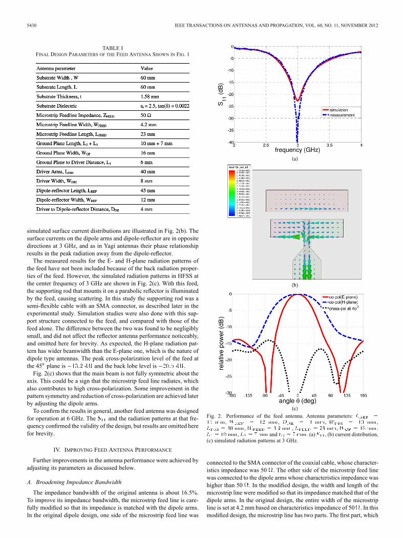
on an Arlon Diclad substrate with a thickness of 1.58 mm, dielectricconstant of 2.5, loss tangent of 0.0022, and an area of 60 60 .Fig. 2(a) shows the HFSS simulated of the antenna in solid line,
and measured in dashed line. The simulated band-width is from 2.78 to 3.28GHz, whichmeans the impedance bandwidthis 16.5% and the measured bandwidth is from 2.81 to 3.28GHz corresponding to impedance bandwidth of 15.4%. Therefore, forboth cases the results are very close to each other and the antenna pro-vides a very good impedance matching at 3 GHz, validating the design.To confirm the backward radiation mechanism, which requires
higher gain in the backward than forward direction , the
5430 IEEE TRANSACTIONS ON ANTENNAS AND PROPAGATION, VOL. 60, NO. 11, NOVEMBER 2012
TABLE IFINAL DESIGN PARAMETERS OF THE FEED ANTENNA SHOWN IN FIG. 1
simulated surface current distributions are illustrated in Fig. 2(b). Thesurface currents on the dipole arms and dipole-reflector are in oppositedirections at 3 GHz, and as in Yagi antennas their phase relationshipresults in the peak radiation away from the dipole-reflector.The measured results for the E- and H-plane radiation patterns of
the feed have not been included because of the back radiation proper-ties of the feed. However, the simulated radiation patterns in HFSS atthe center frequency of 3 GHz are shown in Fig. 2(c). With this feed,the supporting rod that mounts it on a parabolic reflector is illuminatedby the feed, causing scattering. In this study the supporting rod was asemi-flexible cable with an SMA connector, as described later in theexperimental study. Simulation studies were also done with this sup-port structure connected to the feed, and compared with those of thefeed alone. The difference between the two was found to be negligiblysmall, and did not affect the reflector antenna performance noticeably,and omitted here for brevity. As expected, the H-plane radiation pat-tern has wider beamwidth than the E-plane one, which is the nature ofdipole type antennas. The peak cross-polarization level of the feed atthe 45 plane is and the back lobe level is .Fig. 2(c) shows that the main beam is not fully symmetric about the
axis. This could be a sign that the microstrip feed line radiates, whichalso contributes to high cross-polarization. Some improvement in thepattern symmetry and reduction of cross-polarization are achieved laterby adjusting the dipole arms.To confirm the results in general, another feed antenna was designed
for operation at 6 GHz. The and the radiation patterns at that fre-quency confirmed the validity of the design, but results are omitted herefor brevity.
IV. IMPROVING FEED ANTENNA PERFORMANCE
Further improvements in the antenna performance were achieved byadjusting its parameters as discussed below.
A. Broadening Impedance Bandwidth
The impedance bandwidth of the original antenna is about 16.5%.To improve its impedance bandwidth, the microstrip feed line is care-fully modified so that its impedance is matched with the dipole arms.In the original dipole design, one side of the microstrip feed line was
Fig. 2. Performance of the feed antenna. Antenna parameters:, , , ,
, , , ., and . (a) , (b) current distribution,
(c) simulated radiation patterns at 3 GHz.
connected to the SMA connector of the coaxial cable, whose character-istics impedance was 50 . The other side of the microstrip feed linewas connected to the dipole arms whose characteristics impedance washigher than 50 . In the modified design, the width and length of themicrostrip line were modified so that its impedance matched that of thedipole arms. In the original design, the entire width of the microstripline is set at 4.2 mm based on characteristics impedance of 50 . In thismodified design, the microstrip line has two parts. The first part, which

IEEE TRANSACTIONS ON ANTENNAS AND PROPAGATION, VOL. 60, NO. 11, NOVEMBER 2012 5431
Fig. 3. Modified microstrip feed line case. (a) Microstrip line parameters, (b), (c) input impedance. The other antenna parameters are the same as men-
tioned in Table I.
is connected to the SMA connector of the co-axial cable, has a lengthand width of 10 mm and 4.2 mm respectively, for the characteristicsimpedance of 50 . The second part, which is connected to the dipolearms has a length and width of 33 mm and 1 mm respectively, and actsas an impedance transformer to match the characteristic impedance tothat of the dipole arms. The width of the transmission line, which isconnected between the ground plane and other dipole arm is also mod-ified and set to 1 mm.Fig. 3(a) shows the layout of the modified microstrip feed line.
Fig. 3(b) shows that, for the modified feed line case, thebandwidth is from 2.85 to 3.82 GHz. That means 29.1% impedancebandwidth is achieved in this case. Fig. 3(c) shows the Smith chartcorresponding to the input impedance of the two cases. For the mod-ified feed line case, the matching section has moved the impedanceloop to the centre of Smith chart, so the entire loop is within a constant
, indicating a broadband . The E- and H-planepatterns are unchanged with the modified feed line and therefore areomitted for brevity.
Fig. 4. Feed antenna with unequal dipole arms. Antenna parameters are thesame as mentioned in Table I, except and
. (a) geometry, (b) radiation patterns at 3 GHz.
B. Improving Pattern Symmetry
The original antenna is symmetric about the x-z plane which shouldgive symmetrical E-plane radiation patterns. However with the pres-ence of the transmission line, the co-polarization patterns of the an-tenna are not symmetric at the principal planes, which also cause highercross-polarizations at the 45 plane. To improve the E-plane patternsymmetry for co-polarization, the lengths of the dipole arms are madeunequal, but keeping the total dipole length the same. Using this tech-nique, a good symmetry is found for co-polarization patterns, whichalso improves the cross-polarization level at 45 plane. This techniqueis a useful solution, and does not change the overall structure of theantenna.Fig. 4(a) shows the left and right dipole arms, with unequal lengths,
connected through the microstrip line. The width of the dipole armsis the same as the original case. With the change of the dipole armslengths, now the symmetry about the x-z plane is slightly changed andthe center point of the dipole-reflector is also adjusted accordingly.The radiation patterns of the modified antenna at 3 GHz are shown inFig. 4(b). As shown in the figure, the E- and H-plane co-polar patternsare more symmetrical compared to the original case. The cross-polar-ization level is also lower than the original case and it isat 45 plane, which is about improvement from the originalcase. The is unchanged with this case and therefore omitted fromstudy.

5432 IEEE TRANSACTIONS ON ANTENNAS AND PROPAGATION, VOL. 60, NO. 11, NOVEMBER 2012
Fig. 5. Computed feed efficiency of a symmetrical parabolic reflector as a func-tion of its subtended angle. The efficiency is calculated using the feed radiationpatterns at 3 GHz.
Fig. 6. Themicrostrip fed printed dipole on a 45 cm reflector with a focal lengthof 11.25 cm. The feed is connected to a semi rigid coaxial cable RG 402 and ismounted centrally on the reflector by foam.
V. FEED PERFORMANCE WITH A PARABOLIC REFLECTOR ANTENNA
The performance of the feed on a parabolic reflector antenna is in-vestigated following the established methods in [19], [20]. The resultsfor the gain factor, i.e., the overall efficiency, of the reflector are shownin Fig. 5, which excludes all the losses. It indicates a peak efficiency of78% with a reflector having an aperture angle of 67.5 , correspondingto an f/D of 0.375. This should be compared with 82% efficiency oftheoretical feeds, as discussed in [19]. Fig. 5 also shows that the feedefficiency drops to 65%, for a deeper reflector with , oraperture angle 90 .In the antenna laboratory a small 45 cm parabolic reflector was avail-
able, which had an f/D of 0.25. Its focal length was 11.25 cm, whichis slightly larger than one wavelength at 3 GHz. The dipole feed wasconnected to an RG 402 semi rigid cable with an outer diameter of 3.6mm, and mounted on the reflector through a central hole on the para-bolic reflector without any strut support, as shown in Fig. 6.The measured radiation patterns of the reflector are shown in Fig. 7,
indicating a gain of 20 dBi at 3 GHz, which includes the feed mismatchand external feed line losses. This corresponds to an overall efficiencyof 50.3%. Excluding these losses the actual reflector gain increases to20.4 dBi, which corresponds to an efficiency of 55%, at the feed inputafter the SMA connector. Thus, compared to Fig. 5, the measured ef-ficiency is lower than the calculated efficiency of 65%, by about 10%.This difference can be attributed to a few factors, inherent in the feedand measurement. The microstrip feed has metallization and dielectric
Fig. 7. Measured radiation patterns of the reflector-feed antenna at 3 GHz. Re-flector diameter and focal length are 45 mm, and 11.25 cm. Feed parametersare: , , , ,
, , , ., and .
TABLE IIGAIN, LOSSES AND EFFICIENCY OF THE FEED ANTENNA WITH A 45 CM
REFLECTOR AT THREE DIFFERENT FREQUENCIES
losses, which were calculated to be about 0.3 dB. The feed line also ra-diates the cross-polarized field, which is not included in the measuredgain. In addition, the reflector focal length of is too small at 3GHz. Thus the reflector is at the near field distance of the feed, causingsome phase errors. Table II shows the analysis of the reflector gain, andmagnitude of various losses.Finally, it should be noted that we have verified the feed performance
on a deep dish with an f/D of 0.25, which from Fig. 5 gives a theoreticalefficiency of 65%. To improve the efficiency we either need a reflectorwith f/D of 0.375, which from Fig. 5 gives a higher efficiency of 78%.Or, use an appropriate reflector with an elliptical aperture shape. Wedid not have access to such reflectors to verify the feed performancefor higher efficiencies.
VI. CONCLUSION
In this communication, a very simple microstrip fed printed dipoleantenna was presented as a feed for prime focus reflectors. It achieved16.5% impedance bandwidth at 3 GHz and provided good radiationcharacteristics with wider H-plane patterns then the E-plane patterns.The feed antenna was further modified by including an impedancematching section in series with the feed transmission line to achieve29.1% impedance bandwidth. The pattern symmetry was improvedand cross-polarization level was decreased by by making thedipole arm lengths unequal.Based on the radiation characteristics of the feed, the reflector pro-
vided radiation with elliptical beam shape (the E-plane pattern wasslightly wider than the H-plane pattern). With a 45 cm parabolic re-flector, having f/D of 0.25, the measured efficiency including all losses

IEEE TRANSACTIONS ON ANTENNAS AND PROPAGATION, VOL. 60, NO. 11, NOVEMBER 2012 5433
was 50.3%. Excluding the losses external to the feed and the peak ef-ficiency was found to be 55%, which corresponds to 65% theoreticalefficiency, calculated using the feed radiation patterns. For further eval-uation, a second feed for operation at 6 GHz was also designed, fab-ricated and used with the same reflector. The measured patterns andefficiencies were similar and omitted for brevity. As the feed produceselliptical beam shapes, it is suitable as a feed for illuminating a reflectorwith elliptic aperture shape. Note also that as Fig. 5 shows, the feed ismore suitable for a reflector with larger f/D of 0.375.
ACKNOWLEDGMENT
The authors would like to thank C. Smit for the fabrication of theantenna and B. Tabachnick for the antenna radiation pattern measure-ments.
REFERENCES[1] A. D. Olver, P. J. B. Clarricoats, A. A. Kishk, and L. Shafai, Microwave
Horns and Feeds, ser. 39. London, U.K.: Institute of Electrical Engi-neers, 1994.
[2] P. J. B. Clarricoats and A. D. Olver, Corrugated Horns for MicrowaveAntennas. London, U.K.: Peter Peregrinus, 1994.
[3] G. L. James and D. P. S. Malik, “Towards the theoretical design ofsplash-plate feeds,” Electron. Lett., vol. 11, no. 24, pp. 593–594,1975.
[4] P. Newham, “A high efficiency splash plate feed for small reflectorantennas,” in Proc. IEEE Antennas Propag. Int. Symp., 1985, pp.420–423.
[5] P.-S. Kildal and S. A. Skyttemyr, “Dipole-disk antenna withbeam-forming ring,” IEEE Trans. Antennas Propag., vol. 30, no.4, pp. 529–534, 1982.
[6] C. C. Cutler, “Parabolic-antenna design for microwaves,” Proc. IRE,vol. 35, no. 11, pp. 1284–1294, 1947.
[7] G. T. Poulton and T. S. Bird, “Improved rear-radiating waveguide cupfeeds,” in Proc. IEEE Antennas Propag. Int. Symp., Mill Valley, CA,1986, vol. 1, pp. 79–82.
[8] P.-S. Kildal, “The hat feed: A dual-mode rear-radiating waveguide an-tenna having low cross polarization,” IEEE Trans. Antennas Propag.,vol. 35, no. 9, pp. 1010–1016, 1987.
[9] J. Hansen, A. A. Kishk, P.-S. Kildal, and O. Dahlsjo, “High perfor-mance reflector hat antenna with very low side lobes for radio-link ap-plications,” in Proc. Antennas Propag. Soc. Int. Symp., 1995, vol. 2,pp. 893–896.
[10] D. M. Pozar and D. Schaubert, Microstrip Antennas: The Analysis andDesign of Microstrip Antennas and Arrays. London, U.K.: Instituteof Electrical Engineers, 1994.
[11] P. S. Hall and C. J. Prior, “Microstrip feeds for prime focusfed reflector antennas,” Proc. Inst. Elect. Eng., vol. 134, no.2, pp. 185–193, 1987.
[12] A. A. Kishk and L. Shafai, “Optimization of microstrip feed geometryfor prime focus reflector antennas,” IEEE Trans. Antennas Propag.,vol. 37, no. 4, pp. 445–451, 1989.
[13] N. Kaneda, W. R. Deal, Y. Qian, R.Waterhouse, and T. Itoh, “A broad-band planar quasi-Yagi Antenna,” IEEE Trans. Antennas Propag., vol.50, no. 8, pp. 1158–1160, 2002.
[14] G. Zheng, A. A. Kishk, A.W. Glisson, and A. B. Yakovlev, “Simplifiedfeed for modified printed Yagi antenna,” Electron. Lett., vol. 40, no. 8,pp. 464–466, 2004.
[15] G. Zheng, A. A. Kishk, A. B. Yakovlev, and A. W. Glisson, “A broadband printed bow-tie antenna with a simplified feed,” inProc. AntennasPropag. Society Int. Symp., CA, Jun. 2004, vol. IV, pp. 4024–4027.
[16] A. A. Eldek, A. Z. Elsherbeni, and C. E. Smith, “Wideband modifiedprinted bow-tie antenna with single and dual polarization for C andX-band applications,” IEEE Trans. Antennas Propag., vol. 53, no. 9,pp. 3067–3072, 2005.
[17] Ansoft HFSS Version 12 [Online]. Available: http://www.ansoft.com[18] C. A. Balanis, Antenna Theory: Analysis and Design, 2nd ed. New
York: Wiley, 1997.[19] S. Silver, Microwave Antenna Theory and Design. London, U.K.:
Peter Peregrinus Ltd., 1984.[20] P.-S. Kildal, “Factorization of the feed efficiency of paraboloids and
Cassegrain antennas,” IEEE Trans. Antennas Propag., vol. AP-33, no.8, pp. 903–908, 1985.
Radiation by a Slotted Conducting Elliptic CylinderCoated by a Nonconfocal Dielectric
Biglar N. Khatir and Abdel R. Sebak
Abstract—The characteristics of a slot antenna on a perfectly conductingelliptic cylinder coated by a nonconfocal dielectric are investigated ex-perimentally. Tow prototypes of non-coated and dielectric-coated ellipticslot antennas are designed, fabricated, and tested. The simulations andmeasurements results of non-coated and nonconfocal coated slot antennasare compared and discussed. It is found that the radiation patterns due tocoating material become more directive.
Index Terms—Elliptic cylinder, experiment, nonconfocal coated, slot an-tenna.
I. INTRODUCTION
Wireless communications technology is one of the most rapidlygrowing fields. An antenna is a key element that makes wirelesscommunications possible. One of the most popular antennas is the slotantenna which is widely used in many wireless systems such as radarand satellite communications, space vehicles, aircrafts, missiles, and instandard desktop microwave sources for research purposes Dependingon the application, slot antennas are mounted on bodies which havedifferent shapes. The slotted elliptic cylinder is an attractive geometrybecause of some advantages including extra design parameters and forsome applications where the elliptic cylinder provides a useful modelfor the mounting body.Generally, slot antennas mounted on aircrafts, space shuttles, and
missiles are coated by materials for different purposes. For example,the slot antenna on the space shuttle is covered by heat-shielding tiles.In some applications, the coated materials can protect slot antennasfrom the oxidations or damages. Also, the electromagnetic propertiesof (loaded and coated) materials can be used to further control the ra-diated power as an extra design parameter. Therefore, extensive inves-tigations are reported about the characteristics of slotted antennas onelliptic [1]–[10] cylinders loaded and/or coated by confocal or noncon-focal [9], [10] materials. The number of design parameters increaseswhen the coating is nonconfocal including uniform and non-uniformcoating of the slot antenna.Some related experimental works are also reported in which the
cylindrical slot antennas are fabricated and tested [11]–[15]. However,for those antennas the slots are mounted on rectangular or circularcylinders. In this communication, we introduce a slot antenna in whichthe slot is mounted on an elliptic cylinder with an extra degree of de-sign parameters. In particular, design, fabrication, and testing of thenon-coated and dielectric-coated elliptic cylinder slot antennas are pre-sented. The simulations and measurements results of these antennasare compared and discussed. The proposed antennas are very usefulin several aerospace and military communication systems and in fixedstations for personal and beacons communication services where, for
Manuscript received March 03, 2012; revised June 02, 2012; accepted July02, 2012. Date of publication July 11, 2012; date of current version October 26,2012.The authors are with the Department of Electrical and Computer Engineering,
Concordia University, Montreal QC, Canada (e-mail: [email protected];[email protected]).Color versions of one or more of the figures in this communication are avail-
able online at http://ieeexplore.ieee.org.Digital Object Identifier 10.1109/TAP.2012.2207938
0018-926X/$31.00 © 2012 IEEE