louis varney’s g5rv antenna · louis varney’s g5rv antenna g8ode rsars 1691 louis varney (g5rv)...
TRANSCRIPT

Louis Varney’s G5RV Antenna
G8ODE RSARS 1691
Louis Varney (G5RV) –SK, served in the Royal Corps of Signals in an HF
Interception and DF unit , and was rapidly promoted to Captain. He was
demobbed in 1946 and moved to a house in Stony Stratford that had a
garden barely 100ft long - and a need for a multi-band HF antenna.
Eventually Louis came up with the design now universally known as
“The G5RV Multi-band HF Dipole”
Louis later joined the Royal Signals Amateur Radio Society (RSARS Member 795). The
renowned G5RV is the legacy Louis left the amateur radio fraternity. He never made a penny out
of his invention, that has been copied by many, improved by some , studied by many others using
computers, and manufactured and sold by many companies worldwide.
The following study was carried out using the Freeware MMANA (Method of Moments - ANAlysis)
program, an produced as a tribute to the Society’s famous member.
http://mmhamsoft.amateur-radio.ca/
Note :- This publication only deals with the G5RV using the 300 ohm feeder .
Mario Chomicz G8ODE RSARS 1691
July 2008 issue A Page 1 -25
In September 1990 Louis Varney gave a talk on his G5RV antenna to the Norfolk ARC. The video is in two parts on YouTube
http://www.youtube.com/watch?v=4-6Gq5Od6m4 for part 1 and http://www.youtube.com/watch?v=HnZiEMb-gzE for part 2,
or can be accessed here, on the Southgate ARC website.http://www.southgatearc.org/news/may2011/louis_varney_video.htm

51’ = 15.54m 51’ = 15.54m
Typical UK Height
25’- 40’
7.6 m – 13m
See Note50/75 Ohm Coax Kept as short as practicable
Louis Varney’s Classic G5RV
Drawn by G8ODE RSARS 1691
Coax toAntenna Tuner
Matching Transformer section
Open line 534 ohm (vf = 0.98) : 34 ‘ = 10.36m
Window line 450 ohm (vf = 0.9) : 30.6 = 9.3m
TV Line 300 ohm ( vf = 0.82) : 28’ = 8.5m
NOTE S 1. Louis Varney mentions that he used a choke BALUN . This can made from 12-15m of coax forming a 7-9 turns coil, and tie-wrapped to form a circle 20-25 cm diameter.
2. If the G5RV is erected lower than 12 metres, ensure that the ladder line is well clear of the ground and other objects .
Page 2

SOME IMPORTANT NOTES FOR THIS G5RV ANTENNA STUDY
Although the G5RV can operate 80m-10m, this study has only selected 6 frequencies. The
primary reason for this is because of the limitation of the MMANA “Calculate TAB (Page)
which can only display 6 results on the computer screen at any one time. Since this page
cannot be saved as a file, a “Print-Screen” image had to be made and imported into
PowerPoint for annotation etc . This was also the case for all the other images
The study only investigates the horizontal Far Fields as these predominantly produce the
“low Angle” radiation used in DX QSOs. It was therefore felt that these would be of most
interest .
One thing to notice is the current which is displayed as a magnitude value. This can be
seen to vary in size and relates to the impedance of the antenna as seen by the
transceiver for the various frequencies studied.
The G5RV’s open wire ladder line acts as a variable matching transformer reducing the
impedance presented at the centre feed point to more easily managed values. This enables
the antenna matching unit (ATU) connected to the transceiver to easily adjust the SWR to a
value close to 1:1. Only on the 20m band does this open wire line behave as a 1:1 ratio
transformer. The SWR values shown on the “Calculate “ page indicate the values the ATU
has to reduce to a value close to 1:1 .
Page 3

Classic G5RV-Flat top T Radiation Patterns With vertical 300R feeder 12.66 m long model & bottom @ +1m
G8ODE RSARS 1691
Antenna SWR optimised @14.15 MHz feeder is open wire
Page 4

Plan View
3D View
3.75 MHz Horizontal
Radiation Patterns
Classic G5RV-Flat top T
Radiation Patterns 300R feeder bottom @ +1m above
“Real” Ground & Antenna optimised
for SWR 1.53 :1 @ 14.15 MHz
G8ODE RSARS 1691Page 5

7.05 MHz Horizontal
Radiation Patterns
Plan View
3D View
G8ODE RSARS 1691
Classic G5RV-Flat top T
Radiation Patterns 300R feeder bottom @ +1m above
“Real” Ground & Antenna optimised
for SWR 1.53 :1 @ 14.15 MHz
Page 6

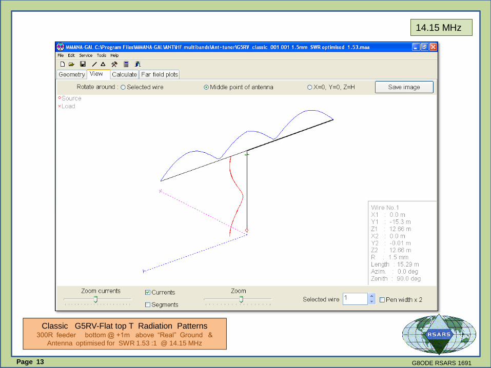
14.15 MHz Horizontal
Radiation Patterns
Plan View
3D View
G8ODE RSARS 1691
Classic G5RV-Flat top T
Radiation Patterns 300R feeder bottom @ +1m above
“Real” Ground & Antenna optimised
for SWR 1.53 :1 @ 14.15 MHz
Page 7

Plan View
18.12 MHz Horizontal
Radiation Patterns
3D View
G8ODE RSARS 1691
Classic G5RV-Flat top T
Radiation Patterns 300R feeder bottom @ +1m above
“Real” Ground & Antenna optimised
for SWR 1.53 :1 @ 14.15 MHz
Page 8

Plan View
21.20 MHz Horizontal
Radiation Patterns
3D View
G8ODE RSARS 1691
Classic G5RV-Flat top T
Radiation Patterns 300R feeder bottom @ +1m above
“Real” Ground & Antenna optimised
for SWR 1.53 :1 @ 14.15 MHz
Page 9

24.94MHz Horizontal
Radiation Patterns
Plan View
3D View
G8ODE RSARS 1691
Classic G5RV-Flat top T
Radiation Patterns 300R feeder bottom @ +1m above
“Real” Ground & Antenna optimised
for SWR 1.53 :1 @ 14.15 MHz
Page 10

3.75 MHz
G8ODE RSARS 1691
Classic G5RV-Flat top T Radiation Patterns 300R feeder bottom @ +1m above “Real” Ground &
Antenna optimised for SWR 1.53 :1 @ 14.15 MHz
Page 11

7.05 MHz
G8ODE RSARS 1691
Classic G5RV-Flat top T Radiation Patterns 300R feeder bottom @ +1m above “Real” Ground &
Antenna optimised for SWR 1.53 :1 @ 14.15 MHz
Page 12
14.15 MHz
G8ODE RSARS 1691
Classic G5RV-Flat top T Radiation Patterns 300R feeder bottom @ +1m above “Real” Ground &
Antenna optimised for SWR 1.53 :1 @ 14.15 MHz
Page 13

18.12 MHz
G8ODE RSARS 1691
Classic G5RV-Flat top T Radiation Patterns 300R feeder bottom @ +1m above “Real” Ground &
Antenna optimised for SWR 1.53 :1 @ 14.15 MHz
Page 14

21.20 MHz
G8ODE RSARS 1691
Classic G5RV-Flat top T Radiation Patterns 300R feeder bottom @ +1m above “Real” Ground &
Antenna optimised for SWR 1.53 :1 @ 14.15 MHz
Page 15

24.940 MHz
G8ODE RSARS 1691
Classic G5RV-Flat top T Radiation Patterns 300R feeder bottom @ +1m above “Real” Ground &
Antenna optimised for SWR 1.53 :1 @ 14.15 MHz
Page 16

3.75 MHz
Classic G5RV-Flat top T Radiation Patterns
300R feeder bottom @ +1m above “Real” Ground & Antenna optimised for SWR 1.68 :1 @ 14.15 MHz
G8ODE RSARS 1691Page 17

7.05 MHzG8ODE RSARS 1691
Classic G5RV-Flat top T Radiation Patterns
300R feeder bottom @ +1m above “Real” Ground & Antenna optimised for SWR 1.53 :1 @ 14.15 MHz
Page 18
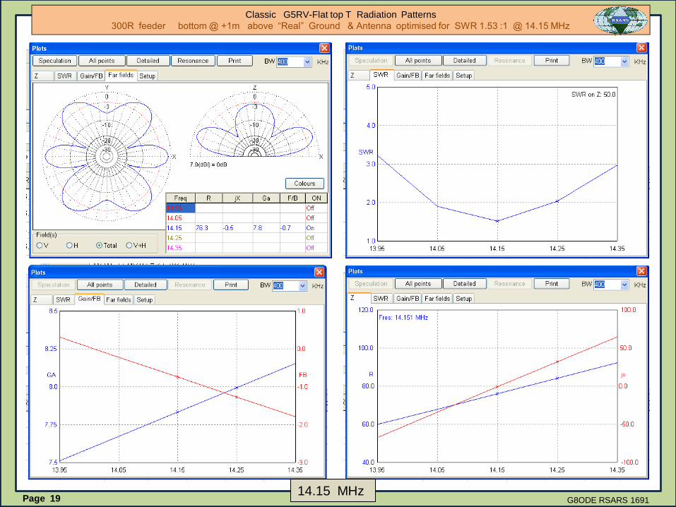
14.15 MHzG8ODE RSARS 1691
Classic G5RV-Flat top T Radiation Patterns
300R feeder bottom @ +1m above “Real” Ground & Antenna optimised for SWR 1.53 :1 @ 14.15 MHz
Page 19

18.12 MHzG8ODE RSARS 1691
Classic G5RV-Flat top T Radiation Patterns
300R feeder bottom @ +1m above “Real” Ground & Antenna optimised for SWR 1.53 :1 @ 14.15 MHz
Page 20
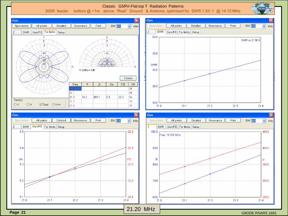
G8ODE RSARS 169121.20 MHz
Classic G5RV-Flat top T Radiation Patterns
300R feeder bottom @ +1m above “Real” Ground & Antenna optimised for SWR 1.53 :1 @ 14.15 MHz
Page 21

24.94 MHz
Classic G5RV-Flat top T Radiation Patterns
300R feeder bottom @ +1m above “Real” Ground & Antenna optimised for SWR 1.53 :1 @ 14.15 MHz
G8ODE RSARS 1691Page 22

Classic G5RV-Flat top T Radiation Patterns
300R feeder bottom @ +1m above “Real” Ground & Antenna optimised for SWR 1.53:1 @ 14.15 MHz
G8ODE RSARS 1691
NOTES:-
The MMANA Program comes with a library of antenna models, one of which is the G5RV. There are also some
transmission lines modelled . The simple checks at the beginning of this study indicated that the section of “300 ohm”
transmission line used in the MMANA-GAL model appeared to be a very close approximation to the ideal. It also
gave some confidence that the program would yield reasonable results for the G5RV. SEE APPENDIX A& B
The MMANA-GAL G5RV model provides reasonable results, that closely match those of other studies that can be
viewed on the internet. The effects of the ground conditions in the real world will obviously modify the way in
which the G5RV operates . This study used the default values provided by the designers of the program . Hopefully
the results are close to the G5RV Louis Varney operated from his QTH in West Sussex England
Page 23

Classic G5RV-Flat top T Radiation Patterns Check of the vertical 300R feeder 5 m long model & bottom @ +1m
G8ODE RSARS 1691
~
0.02m
1.5mm
300R
300R
5 m long
Test Txm Line
NOTE -1 MMANA-GAL cannot model insulation dielectric , consequently the transmission line
has to be modelled as an open wire feeder - shown in the diagram at the side. A 5m length of
line was used for the initial check -- Results are within acceptable limits.
APPENDIX A
1.0 m
Page 24
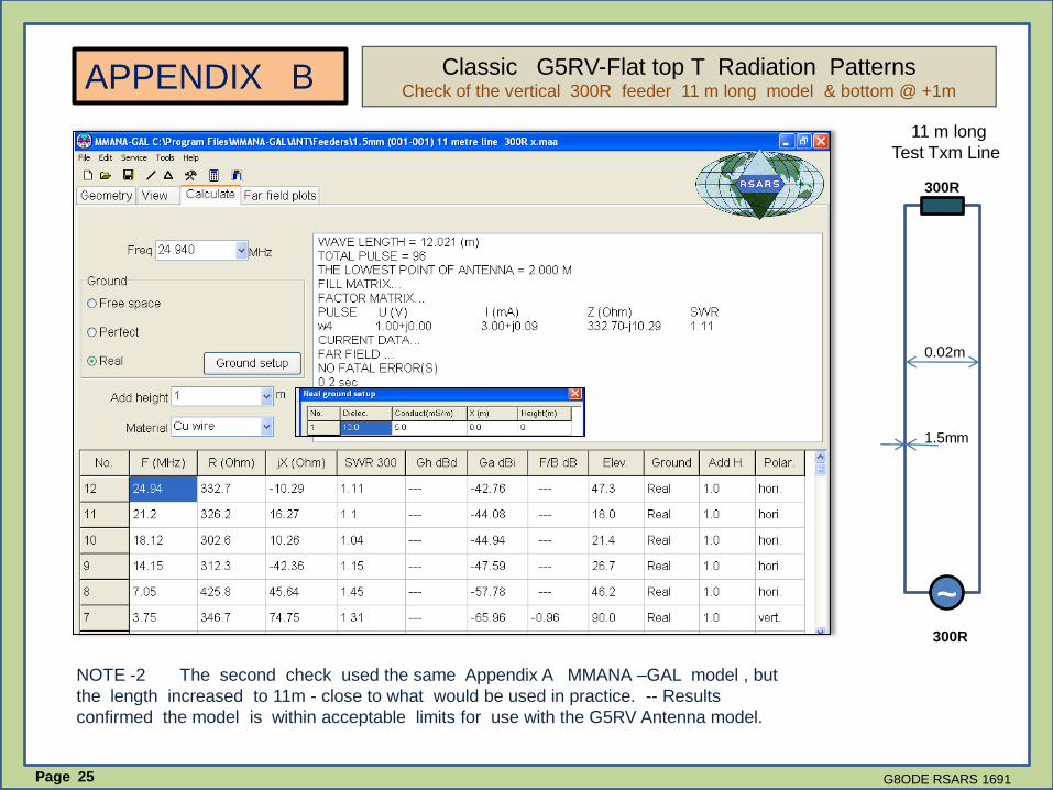
Classic G5RV-Flat top T Radiation Patterns Check of the vertical 300R feeder 11 m long model & bottom @ +1m
G8ODE RSARS 1691
~
0.02m
1.5mm
300R
300R
11 m long
Test Txm Line
NOTE -2 The second check used the same Appendix A MMANA –GAL model , but
the length increased to 11m - close to what would be used in practice. -- Results
confirmed the model is within acceptable limits for use with the G5RV Antenna model.
APPENDIX B
Page 25