loss-in-weight flexwall plus feeders
TRANSCRIPT

3/05 Supersedes 8/04 Page 1 of 7 Document: 3110-C30-2
RELATED DOCUMENTS:3110-C00-1 – Loss-In-Weight FlexWall® Plus Table of Contents3110-C25-1 – Product Description3110-C26-1 – Model Selection Guide3110-C31-1 – Standard Options and Accessories7200-C25-1 – Congrav® ControlsComponents:1300-C21-2 – FlexWall® Screw Trough1300-C21-3 – AC Motor Controller1300-C21-9 – Digital and Analog Scales1300-C21-10 – Digital Load Cell (DigiMASS-2)7200-C30-5 – ISC Controls (ISC-CM, ISC-DC)
WEIGHTS AND MEASURES
Model NumberTotal Scale Capacity
Feeder Dead Weight
Max. Ingredient Capacity
Screw Trough Volume
Extension Hopper Volume Total Volume
Kg (lb) Kg (lb) Kg (lb) liters (cu.ft.) liters (cu.ft.) liters (cu.ft.)DDW-MD5-FW40/5Plus-50DDW-MD5-FW40/6Plus-50 95 (209) 48 (106) 47 (103) 10 (0.35) 50 (1.8) 60 (2.15)
Loss-In-Weight FlexWall® Plus FeedersDDW-MD5-FW40/5Plus, DDW-MD5-FW40/6Plus Model Specifications
Congrav®Controls
MonoblockScale with SingleDigiMASS-2 Load Cell
ScrewandTube
Feeder
ExtensionHopper
Auto Refill Lid
AC MotorControl
SCREW AND TUBE SIZES AND FEED RATES
Screw and Tube Designation
Max. Particle Size Tube ID Tube ODMax. Feed Rate at Specified Screw Speed*
High Screw Speed** Low Screw Speed
mm (inch) mm (inch) mm (inch) RPM (Hz) cu.ft./hr (liters/hr) RPM (Hz) cu.ft./hr
(liters/hr)Spiral Screw and Tube for PowdersS18/13-210 1.5 (0.06) 21 (0.83) 25 (0.98) 144 (75) 0.708 (20)S18/19-210 1.5 (0.06) 21 (0.83) 25 (0.98) 144 (75) 1.16 (32.8)S20/24-210 0.5 (0.02) 21 (0.83) 25 (0.98) 144 (75) 1.93 (54.7)S24/35-260 1.0 (0.04) 26 (1.02) 30 (1.18) 144 (75) 4.35 (123)S28/22-320 2.0 (0.08) 32 (1.26) 35 (1.38) 144 (75) 3.61 (102)S28/35-320 2.0 (0.08) 32 (1.26) 35 (1.38) 144 (75) 6.01 (170)S33/35-350 1.0 (0.04) 35 (1.38) 38 (1.50) 144 (75) 8.47 (240)S40/27-443 2.2 (0.08) 44.3 (1.74) 48.3 (1.90) 144 (75) 9.56 (271)S40/42-443 2.2 (0.08) 44.3 (1.74) 48.3 (1.90) 144 (75) 15.3 (433)Spiral Screw and Tube for Granules/PelletsS18/13-320 7.0 (0.28) 32 (1.26) 35 (1.38) 251 (75) 1.73 (49) 144 (75) 0.991 (28.1)S18/19-320 7.0 (0.28) 32 (1.26) 35 (1.38) 251 (75) 2.83 (80.2) 144 (75) 1.62 (45.9)S20/24-320 6.0 (0.24) 32 (1.26) 35 (1.38) 251 (75) 4.71 (133) 144 (75) 2.7 (76.5)S24/35-350 5.5 (0.22) 35 (1.38) 38 (1.50) 251 (75) 10.6 (301) 144 (75) 6.09 (172)S28/22-443 8.2 (0.32) 44.3 (1.74) 48.3 (1.90) 251 (75) 8.81 (249) 144 (75) 5.05 (143)S28/35-443 8.2 (0.32) 44.3 (1.74) 48.3 (1.90) 251 (75) 14.7 (416) 144 (75) 8.42 (238)S33/35-443 5.7 (0.22) 44.3 (1.74) 48.3 (1.90) 251 (75) 20.7 (586) 144 (75) 11.9 (336)Blade Screw and TubeB28/28-320 2.0 (0.08) 32 (1.26) 38 (1.50) 144 (75) 3.68 (104)B32/38-350 1.5 (0.06) 35 (1.38) 38 (1.50) 144 (75) 7.14 (202)B40/32-443 2.2 (0.08) 44.3 (1.74) 48.3 (1.90) 144 (75) 9.56 (271)B40/46-443 2.2 (0.08) 44.3 (1.74) 48.3 (1.90) 144 (75) 14.5 (409)Mass Flow Screw and TubeF33/22/35/K24-350 1.0 (0.04) 35 (1.38) 38 (1.50) 144 (75) 1.81 (51.3)F33/22/35/K13-350 1.0 (0.04) 35 (1.38) 38 (1.50) 144 (75) 3.96 (112)F40/32/46/K15-443 2.2 (0.08) 44.3 (1.74) 48.3 (1.90) 144 (75) 9.37 (265)* The screw speed shown is the standard maximum Loss-In-Weight screw speed (75% of full speed). Higher maximum screw speeds are possible. The Maximum Feed Rates are theoretical values based on a screw filling efficiency of 100% at the specified screw speed. Ingredient flow characteristics determine the screw filling efficiency.** The high screw speed is only available on ‘/6’ models.
3/05 Supersedes 8/04 Page 2 of 7 Document: 3110-C30-2
DDW-MD5-FW40/5Plus, DDW-MD5-FW40/6Plus Model Specifications
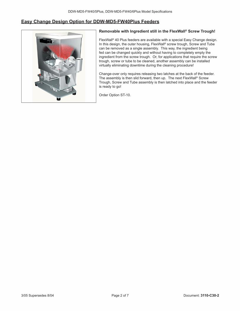
Easy Change Design Option for DDW-MD5-FW40Plus Feeders
Removable with Ingredient still in the FlexWall® Screw Trough!
FlexWall® 40 Plus feeders are available with a special Easy Change design. In this design, the outer housing, FlexWall® screw trough, Screw and Tube can be removed as a single assembly. This way, the ingredient being fed can be changed quickly and without having to completely empty the ingredient from the screw trough. Or, for applications that require the screw trough, screw or tube to be cleaned, another assembly can be installed virtually eliminating downtime during the cleaning procedure!
Change-over only requires releasing two latches at the back of the feeder. The assembly is then slid forward, then up. The next FlexWall® Screw Trough, Screw and Tube assembly is then latched into place and the feeder is ready to go!
Order Option ST-10.
3/05 Supersedes 8/04 Page 3 of 7 Document: 3110-C30-2
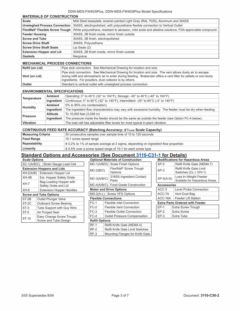
DDW-MD5-FW40/5Plus, DDW-MD5-FW40/6Plus Model SpecificationsMATERIALS OF CONSTRUCTIONScale Mild Steel baseplate, enamel painted Light Gray (RAL 7035), Aluminum and 304SSUnwieghed Process Connection 304SS, electropolished, with polyurethane flexible connection to Vertical OutletFlexWall® Flexible Screw Trough White polyurethane, resistant to abrasion, mild acids and alkaline solutions, FDA approvable compoundFeeder Housing 304SS, 2B finish inside, mirror finish outsideScrew and Tube 304SS, 2B finish, electropolishedScrew Drive Shaft 304SS, PolyurethaneScrew Drive Shaft Seals Lip Seals (2)Extension Hopper and Lid 304SS, 2B finish inside, mirror finish outsideGaskets Neoprene
MECHANICAL PROCESS CONNECTIONSRefill (on Lid) Pipe stub connection. See Mechanical Drawing for location and size.
Vent (on Lid)Pipe stub connection. See Mechanical Drawing for location and size. The vent allows dusty air to escape during refill and atmospheric air to enter during feeding. Brabender offers a vent filter for pellets or non-dusty ingredients. For powders, dust collector is by others.
Outlet Standard is vertical outlet with unweighed process connection.
ENVIRONMENTAL SPECIFICATIONS
TemperatureAmbient Operating: 0° to 40°C (32° to 104°F), Storage: -40° to 40°C (-40° to 104°F)Ingredient Continuous: 0° to 60°C (32° to 140°F), Intermittent: -20° to 60°C (-4° to 140°F)
HumidityAmbient 5% to 95% (no condensation)Ingredient The ingredient flow characteristics may vary with excessive humidity. The feeder must be dry when feeding.
PressureAltitude To 10,000 feet (3,048 m)Ingredient The pressure inside the feeder should be the same as outside the feeder (see Option FC-4 below).
Vibration The load cell has adjustable filter levels for most typical in-plant vibration.
CONTINUOUS FEED RATE ACCURACY (Batching Accuracy: ±1/10,000 Scale Capacity)Measuring Criteria 30 consecutive samples over sample time of 10 to 120 secondsFeed Range 15:1 screw speed rangeRepeatability ± 0.2% to 1% of sample average at 2 sigma, depending on ingredient flow propertiesLinearity ± 0.5% over a screw speed range of 10:1 for each screw type
Standard Options and Accessories (See Document 3110-C31-1 for Details)Scale OptionsSC-1(A/B/C) Strain Gauge Load CellExtension Hoppers and LidsXH-2(A/B) Extension Hopper LidXH-4B Ext. Hopper Safety Grate
XH-7 Bag-Loading Hopper with Safety Grate and Lid
XH-8 Extension Hopper HandlesScrew and Tube OptionsST-2B Outlet Plunger ValveST-2C Outboard Screw BearingST-3 Tube Support with Guy WireST-5 Air Purged Seal
ST-10 Easy Change Screw Trough, Screw and Tube Design
Optional Materials of ConstructionMC-1(A/B/D) Scale Finish Options
MC-2(B/C) FlexWall® Screw Trough Options
MC-3(A/B/C) 316SS Ingredient Contact Parts
MC-4(A/B/C) Food Grade ConstructionMotor and Drive OptionsMD-2(A-L) Screw VFD OptionsFlexible ConnectionsFC-1 Flexible Inlet ConnectionFC-2 Flexible Vent ConnectionFC-3 Flexible Outlet ConnectionFC-4 Outlet Pressure CompensationRefill OptionsRF-1 Refill Knife Gate (NEMA 4)RF-2 Refill Knife Gate Limit SwitchesRF-3 Mounting Flanges for Knife Gate
Modifications for Hazardous AreasXP-2 Refill Knife Gate (NEMA 7)
XP-3 Refill Knife Gate Limit Switches (CL.I, DIV.1)
XP-5(A-D) Loss-In-Weight Feeder Suitable for Hazardous Areas
AccessoriesACC-3 Level Probe Connection ACC-7A Vent Dust BagACC-16A Feeder Lift StationExtra Parts Ordered with FeederEP-1 Extra Screw TroughEP-2 Extra ScrewEP-3 Extra Tube

3/05 Supersedes 8/04 Page 4 of 7 Document: 3110-C30-2
DDW-MD5-FW40/5Plus, DDW-MD5-FW40/6Plus Model SpecificationsMechanical Drawing
E
C
D
ITEM DESCRIPTION1 FlexWall® Plus DDW-MD5-FW40/6Plus Feeder2 Screw Motor3 Paddles4 Extension Hopper - 50L (1.8 cu.ft.)5 Screw6 Tube7 Auto Refill Lid (Optional)8 Inlet (On Auto Refill Lid)9 Vent Dust Bag (Optional)
10 Manual Refill Lid (Optional)11 Unweighed Process Connection12 Monoblock Scale with Single DigiMASS-2 Load Cell
(MD5)13 Feeder Controller (ISC-CM)14 AC Motor Controller (ISC-FC)
Notes:1) All Dimensions are in Millimeters [Inches]2) The Junction Boxes shown are for use with ISC controls - other
Junction Boxes are similar.
Description ‘A’ ‘C’ ‘D’Standard Tube Length 100 [3.9] 115 [4.5] 300 [11.8]Standard Extended Tube Length
250 [9.8] 265 [10.4] 450 [17.7]
Description ‘E’Standard Inlet Diameter 150 [5.9]Standard Larger Inlet Diameter 200 [7.9]
Empty Feeder and Scale Weight Kg (lb)With 50L (1.8 cu.ft.) Extension Hopper 67 (148)
Screw Availability1) All Tubes and standard Spiral Screws are available in Standard
and Standard Extended lengths from stock2) Whenever possible, use a stocked length screw and tube and
move the inlet location to align the inlet and outlet of the feeder with the existing equipment
3) All Spiral Screws requiring modifications, all Blade Screws and all Mass Flow Screws are special order

3/05 Supersedes 8/04 Page 5 of 7 Document: 3110-C30-2
DDW-MD5-FW40/5Plus, DDW-MD5-FW40/6Plus Model Specifications
Typical Feeder Electrical Connections – ISC Controls / OP1 Display - Single Feeder
Interconnecting Cable
ISC-CM(Mounted on Feeder)
(Load Cell wiredat factory)
Communication ‘Out’(RS-485)230VAC
AC Power10A Fuses
ISC-FC(Mounted on Feeder)
(AC Motor wired atfactory - max.1⁄2 HP)
RefillOutput
Feeder ‘On’Output} }
Feeder InterlockInput}
(Wired at factory)(AC Power Wiring, Communication Wiring andFuses are not included with the feeder)
S1 Setpoint 90.549 kg/hAct.value 90.550 kg/h
Congrav® OP 1TECHNOLOGIE
Typical Feeder Electrical Connections – ISC Controls / RC4 Display - Multiple Feeders
Interconnecting Cable
ISC-CM(Mounted on Feeder)
(Load Cell wiredat factory)
Communication ‘Out’(RS-485)
Communication ‘In’ (RS-485)(From Next Feeder)}
230VACAC Power10A Fuses
ISC-FC(Mounted on Feeder)
(AC Motor wired atfactory - max.1⁄2 HP)
RefillOutput
Feeder ‘On’Output} }
Feeder InterlockInput}
(Wired at factory)
Congrav® RC 4
TECHNOLOGIE1 2 3 4 5 6 7 8 9 10 11 12 13 14 15 16
(AC Power Wiring, Communication Wiring andFuses are not included with the feeder)
FEEDER ELECTRICAL SPECIFICATIONS - FEEDERS WITH ISC CONTROLS (See Document 7200-C30-5 for Information on ISC Controls)
Screw/Paddle AC MotorController – ISC-FC
Input Power: 230 VAC, 50/60Hz, Single Phase;Motor Output: 230 VAC, 3 Phase; Motor Control I/O: RS-485 (ISC-CM); 24 VDC Out, 2 Dry Contact Outputs;Enclosure: IP55 (NEMA 12)
Feeder Controller – ISC-CM
Input Power: 24 VDC (from ISC-FC); Load Cell Input: RS-422 (DigiMASS-2); Motor Control Output: RS-485 (ISC-FC); Congrav® Communications (ISC); Enclosure: IP65 (NEMA 12)
Screw/Paddle Motor 1⁄2 HP (0.37 KW), 230/460 VAC, 3 Phase, TEFC
Load Cell Monoblock Scale with a Single DigiMASS-2 Load Cell with Serial Communications (RS-422);Enclosure: IP64 (NEMA 12)

3/05 Supersedes 8/04 Page 6 of 7 Document: 3110-C30-2
DDW-MD5-FW40/5Plus, DDW-MD5-FW40/6Plus Model Specifications
Typical Feeder Electrical Connections – Congrav® S Controls - Single Feeder
JB-1Load Cell Junction Box
for DigiMASS-2(Mounted on Feeder)
JB-2Motor Junction Boxwith Terminals
(Mounted on Feeder)
Load Cell Communications (RS-422)
FieldWiringModule
S1 Setpoint 90.549 kg/hAct.value 90.550 kg/h
Congrav® STECHNOLOGIE
AC Motor Controller (VFD)Allen-Bradley PowerFlex 40Model 22B-V2P3N104115V, Single Phase In230V, 3 Phase Out (0.5 HP)(Provides Class 10overload protection)
115V, 1PhAC Power15A Fuse
(Congrav® S, Field Wiring Module, I/O Cable Set,AC Power Wiring, Wiring to JB-1 and JB-2, andFuses are not included with the feeder)
Typical Feeder Electrical Connections – Congrav® L/M3A Controls - Multiple Feeders
JB-1Load Cell Junction Box
for DigiMASS-2(Mounted on Feeder)
JB-2Motor Junction Boxwith Terminals
(Mounted on Feeder)
Load Cell Communications (RS-422)
DigitalFieldWiringModuleAC Motor Controller (VFD)
Lenze 8200 VectorModel E82EV371_2B230V, Single Phase In230V, 3 Phase Out (0.5 HP)
230V, 1PhAC Power10A Fuse
(Congrav® L/M3A, Field Wiring Modules, I/O Cable Set,AC Power Wiring, Wiring to JB-1 and JB-2, andFuses are not included with the feeder)
Congrav® L/M 3
TECHNOLOGIE1 2 3 4 5 6 7 8 9 10 11 12 13 14 15 16
FEEDER ELECTRICAL SPECIFICATIONS - FEEDERS WITH CONGRAV® CONTROLS (See Document 7200-C00-1 for Information on Congrav® Controls)
Screw/Paddle AC Motor Controller (A-B VFD) – Congrav® S
Input Power: 115 VAC, 50/60Hz, Single Phase; Motor Output: 230 VAC, 3 Phase; Motor Control Input: 0-10V; Enclosure: NEMA 1 with Keypad for Speed Control and Run/Stop
Screw/Paddle AC Motor Controller (Lenze VFD) – Congrav® L/M3A
Input Power: 230 VAC, 50/60Hz, Single Phase; Motor Output: 230 VAC, 3 Phase; Motor Control Input: RS-485; Enclosure: NEMA 1 with Keypad for Speed Control and Run/Stop
Screw/Paddle Motor 1⁄2 HP (0.37 KW), 230/460 VAC, 3 Phase, TEFC
Load Cell for Congrav® Controls Monoblock Scale with a Single DigiMASS-2 Load Cell with Serial Communications (RS-422); Enclosure: IP64 (NEMA 12)
Feeder Mounted Junction Boxes for use with Congrav® Controls
1 NEMA 4 Junction Box for Motor Connections; 1 NEMA 4 Junction Box for DigiMASS-2 Load Cell Connections
3/05 Supersedes 8/04 Page 7 of 7 Document: 3110-C30-2
DDW-MD5-FW40/5Plus, DDW-MD5-FW40/6Plus Model Specifications
Head Office:6500 Kestrel Road
Mississauga, OntarioCanada, L5T 1Z6
Telephone:Toll Free:
Facsimile:Email:
(905) 670-2933(888) 284-4574(905) [email protected]
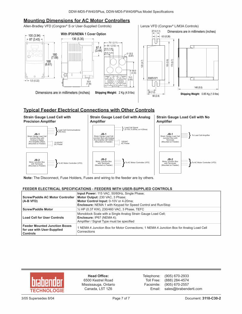
Mounting Dimensions for AC Motor ControllersAllen-Bradley VFD (Congrav® S or User-Supplied Controls) Lenze VFD (Congrav® L/M3A Controls)
Dimensions are in millimeters (inches)
100 (3.94)136 (5.35)87 (3.43)
168(6.61)
180(7.09)
87.4(3.44)
Shipping Weight: 2 Kg (4.9 lbs)
5.5 (0.22) 33.0(1.30)
74.3(2.93)
109.9(4.33)
64.1 (2.52)79.1 (3.11)
Æ 22.2(0.87)
25.6 (1.01)
40.6 (1.60)
With IP30/NEMA 1 Cover Option
150(
5.9)
170(
6.7)
120(
4.7)
60 (2.4)30 (1.2)
140 (5.5)
6.5 (0.26)
E82EV371
27.5 (1.1) Dimensions are in millimeters (inches)
Shipping Weight: 0.85 Kg (1.9 lbs)
Typical Feeder Electrical Connections with Other ControlsStrain Gauge Load Cell with Precision Amplifier
Strain Gauge Load Cell with Analog Amplifier
Strain Gauge Load Cell with No Amplifier
JB-1Strain Gauge Load CellJunction Box withAnalog to DigitalPre-Amplifier (AED)(Mounted on Feeder)
JB-2Motor Junction Boxwith Terminals
(Mounted on Feeder)
Load Cell Communications(RS-422)
To AC Motor Controller (VFD)
10-30VDCDC Power
}
}
JB-1Strain Gauge Load CellJunction Box with AnalogPre-Amplifier (BT-0296)(Mounted on Feeder)
JB-2Motor Junction Boxwith Terminals
(Mounted on Feeder)
Load Cell Signal(0-10V, 0-20ma, or 4-20ma)
To AC Motor Controller (VFD)
120VACAC Power
}
}JB-1
Strain Gauge Load CellJunction Box with
Terminals(Mounted on Feeder)
JB-2Motor Junction Boxwith Terminals
(Mounted on Feeder)
To Load Cell Amplifier
To AC Motor Controller (VFD)
}
}Note: The Disconnect, Fuse Holders, Fuses and wiring to the feeder are by others.
FEEDER ELECTRICAL SPECIFICATIONS - FEEDERS WITH USER-SUPPLIED CONTROLS
Screw/Paddle AC Motor Controller (A-B VFD)
Input Power: 115 VAC, 50/60Hz, Single Phase; Motor Output: 230 VAC, 3 Phase; Motor Control Input: 0-10V or 4-20ma; Enclosure: NEMA 1 with Keypad for Speed Control and Run/Stop
Screw/Paddle Motor 1⁄2 HP (0.37 KW), 230/460 VAC, 3 Phase, TEFC
Load Cell for User ControlsMonoblock Scale with a Single Analog Strain Gauge Load Cell; Enclosure: IP67 (NEMA 4); Amplifier / Signal Type must be specified
Feeder Mounted Junction Boxes for use with User-Supplied Controls
1 NEMA 4 Junction Box for Motor Connections; 1 NEMA 4 Junction Box for Analog Load Cell Connections