loop heat pipes and capillary pumped loops- an ... · loop heat pipes and capillary pumped loops-...
TRANSCRIPT

Loop Heat Pipes and Capillary Pumped Loops- an
Applications Perspective
Dan Butler, Jentung Ku, Theodore Swanson
NASA/GSFC, Code 545, Greenbelt, MD 20771
(301) 286-3478, e-mail: [email protected]
Abstract. Capillary pumped loops (CPLs) and loop heat pipes (LHPs) are versatile two-phase heat transfer devices whichhave recently gained increasing acceptance in space applications. Both systems work based on the same principles and havevery similar designs. Nevertheless, some differences exist in the construction of the evaporator and the hydro-accumulator,and these differences lead to very distinct operating characteristics for each loop. This paper presents comparisons of the twoloops from an applications perspective, and addresses their impact on spacecraft design, integration, and test. Some technicalchallenges and issues for both loops are also addressed.
_TRODUCTION
The use of two-phase thelmal control systems such as Capillary Pumped Loops (CPLs) and Loop Heat Pipes (LHPs)has been increasing substantially in the last several years. They offer greatly increased heat transport capabilities
compared to conventional heat pipes. There have been many publications on CPLs and LHPs with regard to theiroperating characteristics, with some comparisons of these two-phase heat transfer systems, such as Ku
(1993,1997,1999), Maidanik (1997) and Cullimore (1998). However, these papers have focused on the detailedtechnical and analytical attributes of the systems, without an emphasis on their applications. There have been some
publications addressing applications such as Baker (2001), Chalmers (2000), Ku (1998), and Mcintosh (1999).
However, these papers focused on specific applications, without addressing genetic design considerations that applyto two-phase system implementation. This paper attempts to provide a guide to the attributes and limitations of
these systems, including the requirements on the spacecraft builder for their utilization. A comparison of the twosystems is also offered, to assist in the determination of which system is best suited for a particular application.
LOOP HEAT PIPE AND CAPILLARY PUMPED LOOP OVERVIEW
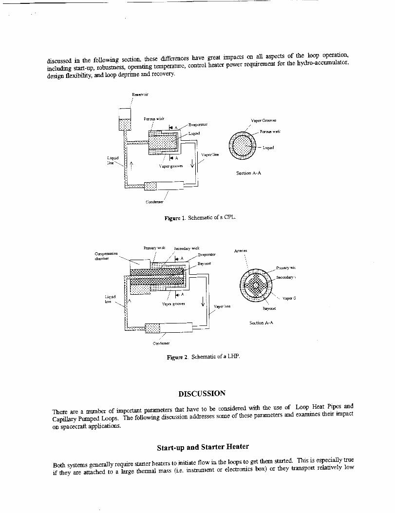
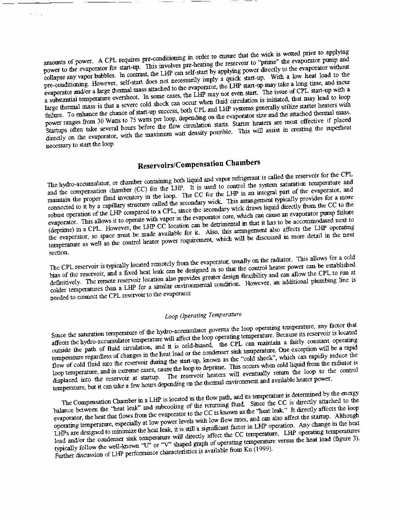
Both LHPs and CPLs are two-phase heat transfer devices that utilize boiling and condensation to transfer heat andthe surface tension force developed by the wick to circulate the fluid. As shown schematically in Figures I and 2,
each device consists of an evaporator, a condenser, a vapor line, a liquid line and a hydro-accumulator. The wick is
required only in the evaporator and hydro-accumulator, the rest of the loop is made of smooth walled tubing. In theliterature, the hydro-accumulator is usually called a reservoir in CPLs and a compensation chamber (CC) in LHPs.
Both loops work based on the same principle: as the heat load is applied to the evaporator, liquid is vaporized and, atthe same time, a meniscus is formed at the liquid/vapor interface in the wick The surface tension force develops a
pressure gradient that moves the vapor to the condenser where it condenses. The liquid is pushed back to theevaporator by the same surface tension force.
A major difference between the two loops is the construction of the evaporator and hydro-acclmmlator, and the
physical location of the latter. In a LHP, the CC is made as an integral part of the evaporator, and is connected tothe evaporator by a secondary wick. In addition, the CC is located directly in the path of the liquid flow. The
reservoir in a CPL is usually located remotely from the evaporator and is outside the path of fluid circulation.Another difference between the two systems is that LHPs use a sintered powder metallic wick with pore sizes on the
order of 1 micron while CPLs use a polyethylene wick with pore sizes on the order of 15 microns. As will be
https://ntrs.nasa.gov/search.jsp?R=20020013939 2020-04-04T10:13:08+00:00Z

discussed m the following section, these differences have great impacts on all aspects of the loop operation,including start-up, robustness, operating temperat_e, control heater power requirement for the hydro-accumulator,design flexibility, and loop deprime and recovery.
Reservoir
//
Porous wick
Vapor Grooves/
Por ous wick
Liquid
Section A-A
Figure I. Schematic ofa CPL.
Liquid/me
Primary w_ek Secondary wick
_Evapor'mor
/
///
Condemer
Arteries
Figure 2. Schematic ofa LHP.
_ Primary wic
$¢eondary
_ \ Vapor G
Bayonet
Section A-A
DISCUSSION
There are a number of important parameters that have to be considered with the use of Loop Heat Pipes andCapillary Pumped Loops. The following discussion addresses some of these parameters and examines their impacton spacecraft applications.
Start-up and Starter Heater
Both systems generally require starter heaters to initiate flow in the loops to get them started. This is especially trueff they are attached to a large thermal mass (i.e. msmunent or electronics box) or they transport relatively low

amounts of power. A CPL requires pre-conditionmg in order to ensure that the wick is wetted prior to applyingpower to the evaporator for start-up. This involves pre-heating the reservoir to "prime" the evaporator pump and
collapse any vapor bubbles. In contrast, the LHP can self-start by applying power directly to the evaporator withoutpre-conditioning. However, self-start does not necessarily imply a quick start-up. With a low heat load to the
evaporator and/or a large thermal mass attached to the evaporator, the LHP start-up may take a long time, and incura substantial temperature overshoot. In some cases, the LHP may not even start. The issue of CPL start-up with alarge thermal mass is that a severe cold shock can occur when fluid circulation is initiate& that may lead to loop
failure. To enhance the chance of start-up success, both CPL and LHP systems generally utilize starter heaters withpower ranges from 30 Watts to 75 watts per loop, depending on the evaporator size and the attached thermal mass.
Startups often take several hours before the flow circulation starts. Starter heaters are most effective if placeddirectly on the evaporator, with the maximum watt density possible. This will assist in creating the supenheat
necessary to start the loop
Reservoirs/Compensation Chambers
The hydro-accumulator, or chamber containing both liquid and vapor refrigerant is called the reservoir for the CPL
and the compensation chamber (CC) for the LHP. It is used to control the system saturation temperature andmamta/n the proper fluid inventory in the loop. The CC for the LHP is an integral part of the evaporator, and
connected to it by a capillary smacture called the secondary wick. This arrangement typically provides for a morerobust operation of the LHP compared to a CPL, since the secondary wick draws liquid directly from the CC to the
evaporator. This allows it to operate with vapor in the evaporator core, which can cause an evaporator pump failure(deprime) in a CPL. However, the LHP CC location can be detrimental in that it has to be accommodated next tothe evaporator, so space must be made available for it. Also, this arrangement also affects the LHP operatingtemperature as well as the control heater power requirement, which will be discussed in more detail m the nextsection.
The CPL reservoir is typically located remotely from the evaporator, usually on the radiator. This allows for a cold
bias of the reservoir, and a fixed heat leak can be designed in so that the control heater power can be establisheddefmilively. The remote reservoir location also provides greater design flexibility and cart allow the CPL to run atcolder temperatures than a LHP for a similar environmental condition. However, an additional plumbing line is
needed to connect the CPL reservoir to the evaporator
Loop Operating Temperature
Since the saturation temperature of the hydro-accumulator governs the loop operating temperature, any factor thataffects the hydro-accumulator temperature will affect the loop operating temperature. Because its reservoir is located
outside the path of fluid circulation, and it is cold-biased, the CPL can maintain a fairly constant operating
temperature regardless of changes in the heat load or the condenser sink temperature. One exception will be a rapidflow of cold fluid into the reservoir during the start-up, known as the "cold shock", which can rapidly reduce the
loop temperature, and in extreme cases, cause the loop to deprime. This occurs when cold liquid from the radiator isdisplaced into the reservoir at startup, The reservoir heaters will eventually return the loop to the controltemperature, but it can take a few hours depending on the themaal environment and available heater power.
The Compensation Chamber in a LHP is located in the flow path, and its temperature is detemained by the energybalance between the '_aeat leak" and subcoolmg of the returning fluid. Since the CC is directly attached to theevaporator, the heat that flows from the evaporator to the CC is known as the "heat leak." It directly affects the loop
operating temperature, especially at low power levels with low flow rates, and can also affect the startup. AlthoughLHPs are designed to minimize the heat leak, it is still a significant factor m LHP operation. Any change m the heat
load and/or the condenser sink temperature will directly affect the CC temperature. LHP operating temperatures
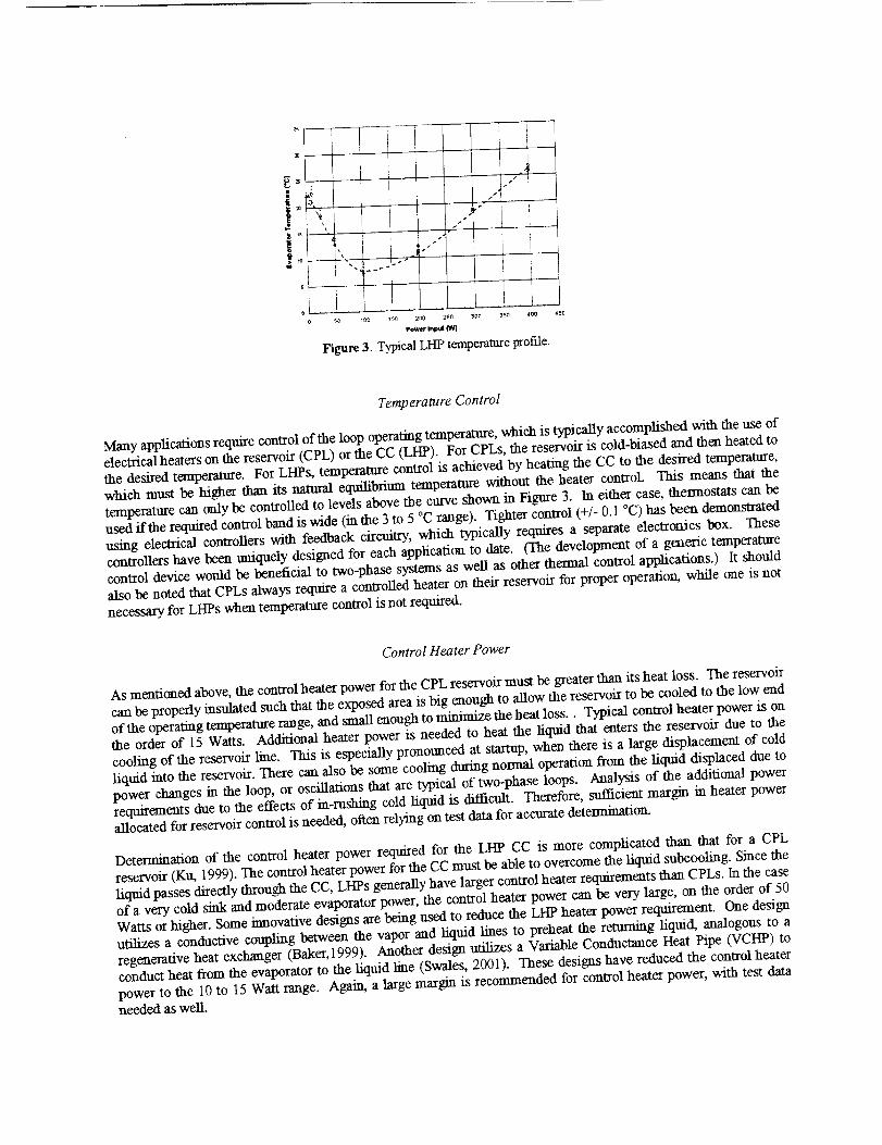
typically follow the well-known "U" or "V" shaped graph of operating temperature versus the heat load (figure 3).Further discussion of LHP performance characteristics is available from Ku (1999).

iI
! t
_o 4oo 45o 2oO 25o _00 35O
Poweri_
Figure 3. Typical LHP temperature profile.
i
s-' L
1
Temperature Control
Many applications require control of the loop operating temperature, which is typically accomplished with the use ofelectrica/heaters on the reservoir (CPL) or the CC (LHP). For CPLs, the reservoir is cold-biased and then heated to
the desired temperature. For LHPs, temperature control is achieved by heating the CC to the desired temperature,which must be higher than its natural equilibrium temperature without the heater control. This means that the
temperature can only be controlled to levels above the curve shown in Figure 3. In either case, thermostats can be
used if the required control band is wide (in the 3 to 5 °C range). Tighter control (+/- O. 1 °C) has been demonstratedusing electrical controllers with feedback circuitry, which typically requires a separate electronics box. These
controllers have been uniquely designed for each application to date. (The development of a generic temperaturecontrol device would be beneficial to two-phase systems as well as other thermal control applications.) It shouldalso be noted that CPLs always require a controlled heater on their reservoir for proper operation, while one is not
necessary for LHPs when temperature control is not required.
Control Heater Power
As mentioned above, the control heater power for the CPL reservoir must be greater than its heat loss. The reservoir
can be properly insulated such that the exposed area is big enough to allow the reservoir to be cooled to the low end
of the operating temperature range, and sma//enough to minimize the heat loss.. Typical control heater power is onthe order of 15 Watts. Additional heater power is needed to heat the liquid that enters the reservoir due to the
cooling of the reservoir line. This is especially pronounced at startup, when there is a large displacement of coldliquid into the reservoir. There can also be some cooling during normal operation from the liquid displaced due to
power changes in the loop, or oscillations that are typJca/of two-phase loops. Analysis of the additional powerrequirements due to the effects of in-rushing cold liquid is difficult. Therefore, sufficient margin m heater powerallocated for reservoir control is needed, oiten relying on test data for accurate detemaination.
Determination of the control heater power required for the LHP CC is more complicated than that for a CPLreservoir (Ku, 1999). The control heater power for the CC must be able to overcome the liquid suboooling. Since the
liquid passes directly through the CC, LI-IPs generally have larger control heater requirements than CPLs. In the case
of a very cold sink and moderate evaporator power, the control heater power can be very large, on the order of 50Watts or higher. Some innovative designs are being used to reduce the LI-IP heater power requirement. One design
utilizes a conductive coupling between the vapor and/iquid lines to preheat the returning liquid, analogous to aregenerative heat exchanger (Baker,1999). Another design utilizes a Variable Conductance Heat Pipe (VCHP) toconduct heat from the evaporator to the liquid line (Swales, 2001). These designs have reduced the control heater
power to the 10 to 15 Watt range. AgaJm, a hrge mar_n is recommended for control heater power, with test dataneeded as well.

Radiator (Condenser)
The radiator should be sized to accommodate the maximum heat load at the worst case hot, end of life conditions,
with at least 10 C of subcoolmg on the returning liquid, and a suggested area margin of 15%. If the condenser candissipate the maximum power applied to the evaporator, temperatt_e control can be achieved over the full range ofthe heat load. On the other hand, if the condenser heat dissipation capability is exceeded, vapor will flow back to
the evaporator. For the CPL, the presence of vapor bubbles in the evaporator is detrimental, resulting in eventual
deprime of the loop. This means that if the radiator cannot reject the entire heat load, a CPL will fail. Oneadvantage of LHPs over CPLs is that when the condenser is fully utilized, vapor will flow back to the evaporator
and CC, automatically raising the CC temperature. Even though the temperature control feature is lost, the loop cancontinue to function. The Lift' will increase in temperature, but continue to run.
Loop Shutdown
One of the greatest attributes of both of these systems is the capability to shut them down when they are not needed
(diode action). This occurs when the power dissipating insmmaent or equipment is powered down, such as when thespacecraft enters a survival mode. The shutdown capability can provide a large savings in heater power. One of the
best methods to accomplish the loop shutdown is with the use of a heater on the reservoir or CC. If a heater isalready employed for temperature control, it can also be used to shut down the loop simply by raising the looptemperature and flooding the loop. However, this requires that the power to the evaporators be removed first. Other
methods of loop shutdown include valves or heaters located on the liquid line.
Pumping Capability
The pumping capability of the two-phase loop is determined by the pore diameter of the wick material utilized in the
evaporator, and is calculated from:
AP = 2 cr/r (1)
where o the surface tension force of the working fluid and r is the radius of curvature of the meniscus at the wick.To date, CPL systems have utilized polyethylene wicks that have typical pore diameters in the 15 micron range,
yielding approximately 3000 pascal (0.4 psi) pumping capability with ammonia at 20 C. Use of lower pore size
metallic wicks in CPL evaporators has been problematic due to the high thermal conductivity through the wick,which leads to bubble generation in the core and deprime of the loop. LI-IPs typically utilize metallic titamum ornickel wicks with pore sizes near 1.0 micron, which produce a much higher pumping capability, 40,000 Pascal (5.8
psi) with ammonia at 20 C. The higher pumping capability has facilitated the use of propylene working fluid inLHPs, which has only 1/3 of the surface tension of ammonia. It is advantageous for applications where the
condenser temperature can drop below the freezing point of ammonia (- 77 °C). With propylene, heaters are notrequired on the radiator because the freezing point of propylene (- 185 °C) is well below typical sink temperatures,However, stanup transients can be more severe when the cold condenser fluid enters the CC, so additional heaters
may be required on the CC.
Number of Evaporator Pumps
Currently only single evaporator systems are flight qualified for both CPLs and LHPs. As demonstrated in ground
testing, implementation of LHPs with more than two evaporators will be problematic due to the integral coupling
between the evaporator and the CC, and the fluid volume requirements. CPLs can utilize more than one evaporatoras long as start-up issues in microgravity are properly addressed. The CAPL 3 flight experiment, currently
manifested for November of 2001 will provide a flight verification of a system with four evaporators and a starterpump (Ku, 1998). A multiple pump system provides multiple heat acquisition sites in a single loop, and can provide
heat sharing, which is the capability to remove heat from an evaporator as well as add heat to it. This cansignificantly reduce heater power requirements as it allows redistribution of "waste heat" to equipment, which

wouldotherwiserequireadditionalheaterpower.Amultiplepumpsystemcanfunctionasa"centralutility"forthe
spacecraft, whereas single pump loops are analogous to smaller "room size" units.
Transport Lines
Both LHPs and CPLs utilize transport lines for the liquid and vapor flowing between the evaporator and the radiator.They are typically smooth walled, standard stainless steel lines ranging from 1.6 ram. (1/16 inch) diameter up to12.7 ram. (% inch) diameter, depending on the heat transport requirements. Unlike heat pipes, transport lines in
CPLs and LHPs do not have wicks, which greatly facilitates their implementation on spacecraft. Determination ofthe line diameter is a compromise between the desire to keep the lines small in order to minimize weight and fluid
charge, and the need to keep the lines large enough to minimize the pressure losses. The frictional pressure lossesin the liquid line and vapor line are inversely proportional to the 4 thand 4.75 t_ power of the line diameter for laminar
and turbulent flows, respectively. Thus, the pressure losses increase rapidly with decreasing diameter. Also notethat additional pressure drops occur in bends and transitions. A total system pressure drop analysis is required forthe use of a two-phase system, including all of the pressure losses in the condenser, evaporator, and lines. It is
recommended that at least a 50% margin exist between the calculated maximum system pressure loss, and the wick
pumping capability (equation 1).
As previously noted, CPLs require an additional transport line from the reservoir to the evaporators. Furthermore,
provisions have to be made to provide subcoolmg to the reservoir line to keep its temperature below the loop setpoint temperature so that bubbles are not introduced into the core of the evaporator and cause the loop to fail. The
approach used on the Terra Spacecraft routes the reservoir line along with the liquid line, with a controlled thelmalcoupling between them. The subcooled liquid from the liquid line provides the necessary cooling for the reservoirline. More recently, an intriguing design which utilizes a reservoir line that is imbedded in the liquid Line, has been
employed for the upcoming Hubble Space Telescope (HST) CPL system (Mclntosh 1998). This not only reducesthe number of transport lines, but also provides direct subcoolmg to the reservoir line.
Careful attention has to be given to the themaal environment of the transport Lines and reservoir lines (in the case ofthe CPL). It is recommended that the transport lines be insulated if possible. If the loop operating temperature isbelow the temperature of the surroundings, there will be a low power limit related to the minimum flow rate
required to achieve the necessary subcoolmg on the working fluid as it enters the evaporator. This is true for both
LHPs and CPLs, although it is more critical for CPLs. If CPLs loose subcoolmg, the loop can faLL whereas a LHPwill just increase its operating temperature (although it may no longer be able to maintain temperature control).
Again, careful analysis and testing in the anticipated Spacecraft environment is needed.
Adverse Height and Tilt considerations
CPLs and LHPs offer at least two orders of magnitude improvement in heat transport capability compared to
traditional heat pipes and VCHPs. They also perform much better when considering adverse heights and tilts, whichis important dining the Spacecraft integration and test phase. In ground testing,, heat pipes are generally limited toan adverse tilt on the order of 0.25 era. (0.1 inch). Most CPL and LHP systems function with adverse tilts of 0.6 can
(0.25 inch) in any direction. CPLs can operate with the evaporator more than 25.4 centimeters (10 inches) above the
condenser, and LHPs have been successfully tested with the evaporator located more than 3 meters (10 feet) abovethe condenser. Both systems work in the reflux mode (condenser above the evaporator), but they can also act as
themaosyphons in this mode even when they are supposedly shut down, due to gravitational effects on the fluid. Toinsure that inoperative loops are shut down, the reservoir or CC temperature will have to be increased above the
evaporator temperature.
Analysis Requirements
The state of the art of the analytical capability for two-phase systems seriously lags the capability for traditionalpassive thelmal control systems, which are based on radiation and conduction heat transfer. This is due to the

relativelyrecentimplementation of two-phase devices, lack of funding for the effort, and most significantly, the
complicated behavior of the two-phase system. Stand-alone models of CPLs and LHPs exist, but implementation ofa turnkey two-phase model with a Spacecratt SINDA model has yet to be developed fully. Steady state analyses are
relatively straightforward, but transient analytical techniques still require development, especially related to systemstart-up. Some of the parameters that must be considered in the analysis of two-phase systems, along withrecommended design margins are:
1. Pressure loss/Ptmaping capability - system pressure loss calculations per section 7 above, 50 % marginrecommended.
2. Radiator capability- Heat rejection margin (15 % recommended) + 10 C of subcooling on the returning
_iquid.3.Spacecraftinternalenvironment- Effecton transportlinesand theCC
4. Adverse Height - ground testing requirements5. Startup Conditions - effect on startup time and power needed
6. Control Heater Power - how much power will be needed
It is recommended that the analysis of two-phase systems be performed by personnel experienced with this type ofwork.
Spacecraft/Instrument Integration
Spacecratl or insmmaent integration can be greatly facilitated with LHPs or CPI_,s, especially compared to
conventional heat pipes. The use of flexible lines for part of the transport lines offers ease of integration, capabilityfor deployable radiators, and mechamcal de-coupling of the radiator from the remainder of the loop. This reduces
the tolerance issues of the transport Rue locations and allows them to be routed around other Spacecraft equipment.This ability to accommodate change is especially useful later in the design process when equipment must berelocated. Another significant advantage is that the flex Rues provide mechanical de-coupling of the radiator or
other components from the remainder of the spacecraft; which reduces mechanical loading (CTE effects, vibration,etc.) in these areas. The flex Rues also facilitate the use of deployable radiators, which can double the effective
radiator area, and reduce weight. In addition, two-phase systems allow greater design flexibility in locating highpower dissipating equipment. This equipment does not have to be located directly on or near to a radiator. One
concern with two-phase loops during integration and test is that additional safety considerations are needed due tothe refrigerant, usually ammonia or propylene. These are important concerns, but can be accommodated with proper
planning. Also, the amount of refrigerant is usually no more than a few pounds for loops rated up to a few kilowatts.
Test Considerations
As stated previously, LHPs and CPLs offer much greater test flexibility than heat pipes, due to a much a larger
pumping capability and static wicking height capability. Nonetheless, there are several issues that should be kept inmind for the test program. If the application differs from previous LHP or CPL applications, a high fidelityengineering development unit is highly recommended. This is particularly true for applications where there is a
large thermal mass, extreme themlal environments, or power ranges and temperature ranges not previously tested.Themaal vacuum tests of two-phase loops are also highly recommended, since ambient tests of the loops do not
accurately reflect the thermal environment that the loops will be exposed to. For example, startups can besignificantly affected by cold condenser temperatures which can only be reached in thermal vacuum tests, and low
power tests are affected by parasitic losses experienced in ambient testing (Baker, 2001).
Another consideration is the test configuration of the loop(s) after integration with the spacecraft. Both CPLs andLHPs have some limits on wicking height and extreme tilt situations. The Spacecraft TV test should include
operation of the loops and accommodations have to be made in the test program to a/low for this. Also, provisionsfor separate ground cooling lines may be required in order to test an item during its assembly and checkout on the
ground, if it is impractical to do so using the two phase loop. Typical cold plate designs include provisions forseparate cooling lines that are hooked up to a chiller to facilitate testing during the integration phase.

CONCLUSIONS
While there are a number of issues related to the implementation of two-phase systems, they do offer a substantial
increase in capability. They provide a great deal of design flexibility, allow tight temperature control with minimalheater power requirements, and enable missions at lower power and weight levels (and cost) that would not be
possible with conventional designs. This is demonstrated by their selection for spacecraft applications by a number
of designers. Although CPLs and LHPs function under the same basic principles, differences m their design lead todifferent operating characteristics, which affects their potential uses. By comparing the similaxities and differencesof the two systems, it is hoped that this paper will help to identify these issues and raise the awareness of them to the
spacecraft community.
DISCLAIMER
The opinions expressed in this paper are solely those of the authors and do not represent an official endorsementfrom NASA or the thermal engineering community.
REFERENCES
Baker, C., Buffer, D., Ku, L, and E. G-rob, "Acceptance Thermal Vacuum Tests of the GLAS Flight Loop Heat Pipe
Systems," m proceedings of STAIF2001, edited by M. E1-Genlq American Institute of Physics, Albuquerque, NewMexico, February 11-14, 2001.
Chalmers, Fredley, J., and M. Kurtz, "A New Era of Instrument Thermal management with Capillary HeatTransport Systems," 51 sr International Astronautical Congress, October 2-6, 2000, Rio de Janeiro, Brazil
CuUimore, B. and J. Baumann, "CPL and LHP Technologies: What are the Differences, What are the Similarities. _r' SAEPaper No. 981587, 28_hInternational Conference on Environmental Systems, Society of Automotive Engineers,
Danvers, Massachusetts, July 13-16, 1998.
Ku, J., "Overview of Capillary Pumped Loop Technology, "ASME HTD-Vol. 236, Heat Pipes and Capillary PumpedLoops, pp. 1-17, 1993.
Kth J., "Recent Advances in Capillary Pumped Loop Technology," AIAA Paper No. 97-3870, 1997 National HeatTransfer Conference, Baltimore, Maryland, August 10-12, 1997.
Ku, J., "Operating C]aaxacteristics of Loop Heat Pipes," SAE Paper No. 1999-01-2007, 29 thInternatT"onal Conference on
Environmental Systems, Society of Automotive Engineers, Denver, Colorado, July 12-15, 1999.Ku, J., ORen_ein, L., Cheung, M., Hoang, T., and S. Yun, "Ground Tests of Capillary Pumped Loop (CAPL 3) Flight
Experiment," SAE paper No. 981812, 2g _ International Conference on Environmental Systems, Society of
Automotive Engineers, Danvers, Massachusetts, July 13-16, 1998.
Maidanik; Y., and Y. Fershtater, "Theoretical Basis and Classi.ficatic_a of Loop Heat Pipes and Capillary PumpedLoops," 10 thInternational Heat Pipe Conference, Stuttgart, Genmany, 1997.
Mclntosh, R., Kaylor, M., Buchko, M., Krohczek; E., and tL Smi_ "A Capillary Pump Loop Cooling System for theNICMOS Instrument," SAE Paper No. 981814, 28 hInternational Conference on Environmental Systems, Society of
Automotive Engineers, Danvers, Massachusetts, July 13-16, 1998.Swales Aerospace, "SWIFT BAT Engineering Test Unit Loop Heat Pipes," Design Review Meeting, April 24, 2001.