longitudinal ship launching
TRANSCRIPT

239Pomorski zbornik Posebno izdanje, 239-249
ISSN 0554-6397Stručni članak(Professional paper)
Daniel ŽgombaE-mail: [email protected] TurkE-mail: [email protected] HadjinaE-mail: [email protected] of Rijeka, Faculty of Engineering, Vukovarska 58, 51000 Rijeka, CroatiaDijana PražićE-mail: [email protected] MargićE-mail: [email protected] "3. maj" d.d., Liburnijska 3, 51000 Rijeka, Croatia
Longitudinal Ship Launching
Abstract
In this paper the ship placement on the slipway and technology of longitudinal launching is analyzed along with conducted static calculation. The first part of the paper describes the longitudinal slipway with all of its equipment made for reception and placement of the particular type of ship. The second part of the paper is describing longitudinal launching of the ship with all of the critical moments during the launching. Every one of the critical positions of the ship is defined and the prevention discussed. Forces and moments of forces for every stage of the launching are calculated with the selected computer software and the static diagram is made and discussed for the particular ship.
Keywords: ship longitudinal lounching, slipway technology, static calculations, static diagram
1. Introduction
This paper examines the sequence of technological activities related to the placement and launching of a ship from a longitudinal approach. Launching is one of the most important moments in the making of a ship. Whether this process is uncertain and risky depends on the method of launch. The most common method of launching is to lower the boat from the slipway. Depending on whether the launch is in the longitudinal or transverse direction, there are two different ways of launching: end launching and side launching. Side launching is common in river shipyards because of the limited sail and the construction of the riverboats themselves. Given that the length of the available shoreline is small for naval shipyards, and sufficient free sail is available, longitudinal
240 Pomorski zbornik Posebno izdanje, 239-249
Longitudinal ...Daniel Žgomba, Anton Turk, Marko Hadjina, Dijana Pražić, Ivan Margić
launching is applied. As the forces that load the ship’s structure occur during launch, it is necessary, in advance, to determine all possible critical positions that threaten the safety of the ship during launching. For this reason, it is necessary to create a launch calculation. The equipment needed to place the ship in the dock, and for the launch, is described in more detail with the attached pictures from the shipyard “3. May”. Static launch calculation was performed in “SIKOB“ software.
The aim of this paper is to illustrate the complexity of the boat placement itself and the longitudinal launch, and to present a number of factors related to the launch itself, which should be considered before assemblying the boat on the slipway. Listed data was received directly from shipyard 3. Maj.
2. Longitudinal slipway for launching of the ship into the water
The longitudinal slipway is a concreted surface that’s used to build, launch and/or overhaul the ship. The inclination of the slipway has to produce a large enough force to overcome friction between the sledges and the surface of the slipway. The most common incline is from 3,5% to 9%, and the ship is usually launched on one or two lanes. Curved design of the slipway has to outline the arc of a circle with the diameter of 1500 – 10 000 m. The purpose of the curved design is to reduce the submersed part of a slipway and the stresses on the structure of the ship. Every slipway consists of the track, the foundation of the slipway, space for scaffolding and the crane track. Types of cranes are bridge cranes with a capacity of 500 - 1500 tons, portal cranes with a capacity of up to 100 tons, mobile cranes, construction cranes. It is necessary to ensure the placement of the cranes in such a way that the reach of the cranes oversrpreads the surface of the whole driveway.
Slipway blocks are a part of the equipment that the hull stands on during construction. The number of blocks must be sufficient to support the weight of the ship, with its equipment, before its delivery to the water. Prior to the start of the construction, a ship supporting plan is drawn up detailing the positions in which the blocks are placed, paying attention to stress concentrations within the hull itself, to prevent deformation of the bottom plating. Therefore, a slipway block must be placed at the intersections of the primary elements of the ship’s structure. The stern and the engine compartment area will have a denser arrangement of bilge blocks under the plating because of the weight in that hull section. The height of the block must be sufficient to allow the sleigh and cradle to be pulled in between the hull and the launching way before launching. Depending on the weight of the ship, the concentration of weights along the length of the hull, and the placement of the elements inside the hull, a supporting plan is drawn up separately for each ship. All this information shows how many slipway blocks are needed, in which for parts of the hull a denser placement of blocks is needed, and in what places a block is allowed to be positioned, so that the hull does not deform. There are several types of slipway blocks:

241Pomorski zbornik Posebno izdanje, 239-249
Longitudinal ...Daniel Žgomba, Anton Turk, Marko Hadjina, Dijana Pražić, Ivan Margić
Steel block – the most common type of slipway block when making large ships and also used in combination with wood.
Block with sand – before launching, the ship must be lowered on the sleigh from slipway blocks. This is accomplished by releasing moisture-protected dry quartz sand through the openings of the block which are demountable.
As the shape of the ship changes along the ship’s lines, the packages must adapt to the shape of the ship. Therefore, the foundations are made with strips that follow the curvature of the hull form and, depending on the position, are placed on the steel blocks, or towers. On Figure 1 the today’s slipway blocks are shown. It shows two basic types of blocks depending on the position below the ship.
Figure 1: Different types of slipway blocks, [1]
Basically, inclined pillars are brackets that prevent the boat from falling from slipway blocks. When building a ship, unexpected situations can occur that could endanger the ship on a slipway, such as the impact of a section on the hull of a ship. In this case, additional forces may occur which could impair the stability of the ship on the supporting blocks. Inclined pillars are also mounted on the supporting parts of the structure to prevent deformation of the hull. When installing the pillar, the angle between the hull and the pillar has to be as small as possible, so the pillar is as long as possible, thus ensuring that there is no bending of the pillar.
Launching way is the fixed part of the slipway that the ship moves on during launching. It usually consists of one or two lanes, of which the distance is 1/3 or 1/4 of the width of the ship. For ships of greater width, three to four lanes can be used. The launching way is composed of two parts: an underwater part and a part above water. During the launch, the ship slides on a launching way while standing on sliding ways. Between the sliding ways and the launching way, the friction should be minimized so that before setting the sliding ways, the launching way shall first be lubricated with a base lubricant and then a sliding lubricant, as seen in figure 2, according to the lubrication plan. Base lubricant can be reused, while sliding lubricant is disposable. Both lubricants are heated in separate boilers before application. Their thickness is

242 Pomorski zbornik Posebno izdanje, 239-249
Longitudinal ...Daniel Žgomba, Anton Turk, Marko Hadjina, Dijana Pražić, Ivan Margić
predetermined at 3-4 mm, but this is difficult to check in practice, so it is important that everything is evenly distributed.
Figure 2: Launching way, [1]
The sliding ways are located between the hull of the ship and the slipway, as seen in figure 3. When launching, the boat slides across the launching way. The sliding ways are made of 300 x 300 oak beams, usually 6-8 meters long and width dependent on the expected specific pressure. The ends of the sliding ways are usually studded with steel with welded lifting eyes for easy handling, and longitudinally interconnected by cables. In order to prevent the sliding ways from being tilted transversely and separated from the hull, they must be attached to the hull by turnbuckles.
Figure 3: Sliding ways with the packaging (on the curved part of the hull), [1]

243Pomorski zbornik Posebno izdanje, 239-249
Longitudinal ...Daniel Žgomba, Anton Turk, Marko Hadjina, Dijana Pražić, Ivan Margić
3. Placement of the selected ship on the slipway
As an example of a ship´s placement on a slipway, a “car carrier” (construction 705) built in the shipyard 3. Maj in Rijeka is presented. The input parameters needed to place the ship in the dock are, [2]:
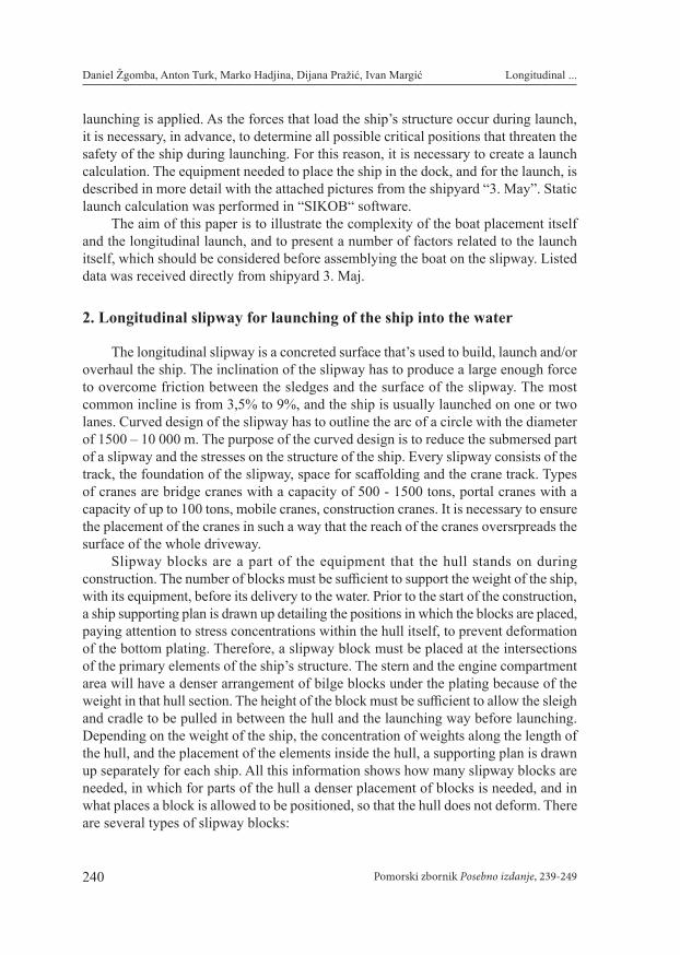
Construction 705 was put together on the slipway No. 2 (cross section of the slipway is shown on figure 4) because the slipway No. 1 was closer to the wall causing the return wave. That wave can have a detrimental impact on the stability of the ship during the launching. This ship has somewhat higher center of gravity and there is a small likelihood of it ejecting the ship from the slipway. The ship can be placed in four ways depending on the shape. Slipway tracks are the ones that allow these placement methods. Which combination of two tracks (out of four) will br used depends on the shape of the vessel. For construction 705, which had a slim hull form with a small flat bottom width relative to the width of the ship, the two closest tracks were taken (second and third, counting from left to right). By comparing the characteristics of the ship and the slipway, first to define the position of the ship by its lenght, breadth and height is needed using the benchmarks on the slipway and the ship´s frames. The selected ship is positioned with the frame number 91 on the benchmark number 15, while its centerline is placed 1200 mm from the benchmarks axis. The height of the ship is defined to be 2300 mm on the benchmark number 1, and 1600 mm on the benchmark number 20. What it actually means is that the stern is positioned higher than the peak of the ship because the slipway has an incline.
244 Pomorski zbornik Posebno izdanje, 239-249
Longitudinal ...Daniel Žgomba, Anton Turk, Marko Hadjina, Dijana Pražić, Ivan Margić
Figure 4: Cross section of the slipway, [2]
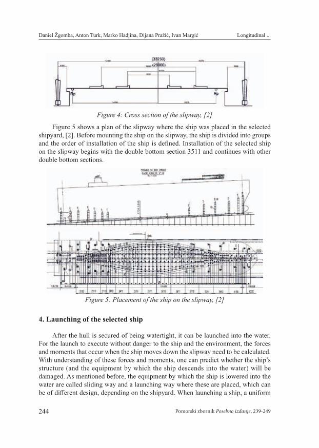
Figure 5 shows a plan of the slipway where the ship was placed in the selected shipyard, [2]. Before mounting the ship on the slipway, the ship is divided into groups and the order of installation of the ship is defined. Installation of the selected ship on the slipway begins with the double bottom section 3511 and continues with other double bottom sections.
Figure 5: Placement of the ship on the slipway, [2]
4. Launching of the selected ship
After the hull is secured of being watertight, it can be launched into the water. For the launch to execute without danger to the ship and the environment, the forces and moments that occur when the ship moves down the slipway need to be calculated. With understanding of these forces and moments, one can predict whether the ship’s structure (and the equipment by which the ship descends into the water) will be damaged. As mentioned before, the equipment by which the ship is lowered into the water are called sliding way and a launching way where these are placed, which can be of different design, depending on the shipyard. When launching a ship, a uniform

245Pomorski zbornik Posebno izdanje, 239-249
Longitudinal ...Daniel Žgomba, Anton Turk, Marko Hadjina, Dijana Pražić, Ivan Margić
motion is assumed at launch, i.e. inertia forces due to uneven ship motion are ignored. Once a ship has moved from its equilibrium position, there is no way to stop it. For this reason, a static launch calculation is created that gives an insight into the launch before the launch itself. The static launch calculation calculates the forces and moments occurring in the critical positions of the ship and compares the stresses with those that the hull and devices can withstand. In a naval shipyard, longitudinal launching is common because of the large area for free drift. For longitudinal launching, the ship is pushed aft first into the sea for a number of reasons. The most important reason is that there are very sensitive devices installed on the stern of the ship, such as steering gear and shaft lines, which must be properly centered. Any major deformation could prevent the operation of these devices and thus prolong the course and cost of building the ship. As explained later, the maximum reaction upon launching occurs on the part that enters the water last. The launch calculation was made for previously mentioned ship using the software called “SIKOB”, which was emloyed during the construction of selected ship in Shipyard 3. May. Today, this program is no longer used, instead a program called “NAPA” is very much in use, which is very similar to the previous one.
The input to the calculation is as follows:For the ship:• Light Weight: W = 12093 t• Center of gravity position from the main frame: LCG = -7.490 m (towards
the stern)• Height of the center of gravity: KG = 15.27 m• Distance from the stern perpendicular to the end of the slipway: A = 93.8 m
For the sliding ways:• Distance from the stern perpendicular to the nearest sliding way: B = 15.8 m• Height from top edge of the launching way to base on 1st sliding way: CRDH1
= 1.78 m• Height from the top edge of the launching way to the base on the last sliding
way: CRDH2 =1.28 m• Length of the sliding ways: CRDL = 138 m• Breadth of the sliding ways: CRDB = 4 m• Length of the cradle: POPPL = 9.6 m
For the launching way:• Lenght: WAYL = 259.8 m• Height between the start and end points of the slipway: WAYH = 13.561 m• Height of the radius segment of the slipway: WAYC = 0.872 m• Water height from the deepest point of the launching way: WATERLEVELS
= 4.723 m [2]

246 Pomorski zbornik Posebno izdanje, 239-249
Longitudinal ...Daniel Žgomba, Anton Turk, Marko Hadjina, Dijana Pražić, Ivan Margić
4.1. First phase of the launch
During the first launch phase, the ship moves uniformly along the dry part of the driveway. The buoyancy force begins to emerge only after the stern perpendicular has touched the surface of the water. Path travelled by the boat can be calculated using the following formula:
Tp = x · m - p · n - (l · m + h - g) (1)Tk = x · m + (L- p) · n - (l · m + h - g) (2)Whereby it is:p – distance from end of the slipway to aft perependicularL – boat lengthl – length of the slipwayh – height of the sliding waysg – water height above the submersed part of the slipway
By now the ship has traveled 54 meters. The position of the center of gravity of the system and the weight of the system (boat + sleigh with packaging) are constant. The force exerted by the ship on the slipway is constant until buoyancy occurs, then the total force of the ship on the sleeve decreases. For the selected ship, that force is described by the total mass of the ship and sliding ways in tonnes and amounts to 12093 tonnes, [1].
4.2. Second phase of the launch
The moment when the center of gravity crosses the end of the slipway is called tipping. At this point it is possible that the moment of buoyancy did not outweigh the mass moment of the whole system and the ship is starting to upright itself. This results in the lifting of the bow from the slipway and thus a high concentration of stresses on the ship’s hull. In order to avoid this, it is necessary to provide sufficient launching way length so that, before that occurs, the ship already has sufficient moment of buoyancy.
Moment of buoyancy in regards to the first point of the sliding ways:M = U · b (3)U – Buoyancy of the boat, tb – distance from center of buoyancy to the first point of the sliding ways, m
Reaction on the crane is calculated by subtracting the buoyancy from the weight of the ship.
Moment of buoyancy in regards to the end of the slipway: M = U · d (4)d – distance from center of buoyancy to the end of the slipway, m

247Pomorski zbornik Posebno izdanje, 239-249
Longitudinal ...Daniel Žgomba, Anton Turk, Marko Hadjina, Dijana Pražić, Ivan Margić
Moment of weight in regards to the end of the slipway:MT = G · e (5)e – distance from center of gravity to the end of the slipway, m
In order to avoid tipping, we have to examine whether the curve of moment of buoyancy on the end of the slipway is located above the curve of the moment of weights on the end of the slipway. This can also be ensured by boarding the ballast into the bow peak to move the mass center of gravity towards the bow and consequently to cross the end of the slipway later. No tipping occurred during launching of the selected ship, [2].
4.3. Third phase of the launch
The third phase begins with the ship’s rotation around the cradle. When rotation starts it means that the moment of buoyancy has overcome the moment of mass and the ship begins to rotate. The position of foces during the third phase of the launch is shown in Figure 6.
Figure 6: Third phase of launching [3]
Waterline during the rotation is calculated by formulas (3.1) and (3.2). CRANE REACTION (Turning) - The start of turning of the selected ship starts
after traveling 184.5 m. The intensity of reaction force is calculated by the difference of buoyancy force and weight force of the ship after traveling 184.5 m. The mentioned software, used for the launch calculation, calculates the reaction force around the cradle when turning occurs, and it is Q = 18590 kN. The force on the cradle can be reduced in two ways: by shifting the center of gravity towards the stern by ballasting the stern tanks, or reducing the trim when placing the ship in the dock [3].
4.4. Fourth phase of the launch
Fourth phase starts when the ship is not in the contact with the slipway. During this phase the ship should be on it’s project draft. In the static calculation, the software has calculated the value of stern, and bow, draft to be,
Tp = 3,29 mTk = 6.64 m This launch did not require the means to stop the ship because the ship was allowed
to drift freely. [2]

248 Pomorski zbornik Posebno izdanje, 239-249
Longitudinal ...Daniel Žgomba, Anton Turk, Marko Hadjina, Dijana Pražić, Ivan Margić
4.5. Stability control
The static launch calculation also includes stability control. It is made for the position of the ship at the beginning of the rotate around the bow, because at that moment the ship rests only on the bow cradle and the reaction force on the cradle is the greatest. The moment of static stability has the same shape as for a ship floating freely on the water. In this part of the calculation, the transverse metacentre Mo is replaced by the reduced metacentre M0’. It is determined by connecting M0 with the point around which the ship turns. Where this connection crosses the vertical line from of the center of gravity, the reduced metacenter M0’ is located [3].
If Mo’ is above the center of gravity of the system during turning, the ship is in stable equilibrium. If this is not the case, then the center of gravity of the system is shifted by the ballast or possibly the front of the sliding ways is moved forward [3].
In the launch calculation, the distance of the reduced metacenter from the center of gravity of the system was calculated to be 0.610 m, which means that the ship is stable [2].
4.6. Slipway stress calculation for the launch of the selected ship
The length of the sliding ways in contact with the slipway during the first phase is 138 m. The reaction force is equal to the weight of the ship because during the first phase the ship did not acquire buoyancy force and the reaction force is at 66.7 m from the cradle. As the ship moves along the slipway, the resulting load moves toward the cradle. At the moment of turning, the stress on the slipway is highest corresponding to 484 N/mm2. The total reaction force is 18589.95 kN, after which the load reduces, and the resultant load remains centered at the same distance from the main frame, [2]. After all the calculations previously mentioned have been done, static launch diagram is made (shown in figure 6).
Figure 7: Static launch diagram [1]

249Pomorski zbornik Posebno izdanje, 239-249
Longitudinal ...Daniel Žgomba, Anton Turk, Marko Hadjina, Dijana Pražić, Ivan Margić
5. Conclusion
The purpose of this research is to present a more in-depth insight into the longitudinal launching of a ship, using the knowledge gained from the shipyard 3. Maj. The launching of the ship is the final, and also the most critical, action in the construction of the ship. In order to perform the launch safely, a series of actions must be performed beforehand. One of the basic is the launch calculation. From the launch calculation, it is possible to predict, in advance, difficulties and dangers during launching. In this paper the calculation of launching of the ship number 705 from the shipyard „3. Maj” was conducted. The characteristics of the slipway and the dimensions of the ship were the input parameters that are needed to describe the position of the ship. With the software called „SIKOB” the values of drafts at stern and bow, the buoyancy and the position of center of gravity were calculated depending on the distance traveled. Also, the software has calculated the pressure distribution on the slipway during standstill and during launch. Those numbers determine the type of lubricating oil and the thickness of layers. It’s imprtant that the coefficients of friction correspond the ones taken in the calculation so that the results are credible. After the final calculation and the static launch chart have been made, the preparatory actions on the ship and the slipway have to be carried out. After that, further preparation of the launch and the launch itself is carried out. The results and procedure of this research may be further used to investigate the launch of the same or similar vessels. This information can be compared to previous research, thus enhancing the technology and launch calculation process itself, unbound to the specific type of ship.
References
1. Shipyard „3.Maj” various materials and documentation, 2018.2. Daniel Žgomba, Final paper: Ship longitudinal launching methodology, University of Rijeka
Faculty of Engineering, 2018.3. Josip Uršić, Ship Stability II, University of Zagreb Faculty of Mechanical Engineering and naval
Architecture, Zagreb, 1991.
