longitudinal control of a platoon of road vehicles ... · longitudinal control of a platoon of road...
TRANSCRIPT
Longitudinal Control of a Platoon of Road Vehicles Equippedwith Adaptive Cruise Control System
ZEESHAN ALI MEMON*, SALEH JUMANI*, AND JAVED LARIK**
RECEIVED ON 2O.02.2012 ACCEPTED ON 21.06.2012
ABSTRACT
Automotive vehicle following systems are essential for the design of automated highway system. Theproblem associated with the automatic vehicle following system is the string stability of the platoon ofvehicles, i.e. the problem of uniform velocity and spacing errors propagation. Different control algorithmfor the longitudinal control of a platoon are discussed based on different spacing policies, communicationlink among the vehicles of a platoon, and the performance of a platoon have been analysed in the presenceof disturbance (noise) and parametric uncertainties. This paper presented the PID (Proportional IntegralDerivative) feedback control algorithm for the longitudinal control of a platoon in the presence of noisesignal and investigates the performance of platoon under the influence of sudden acceleration andbraking in severe conditions. This model has been applied on 6 vehicles moving in a platoon. The platoonhas been analysed to retain the uniform velocity and safe spacing among the vehicles. The limitations ofPID control algorithm have been discussed and the alternate methods have been suggested. Modelsimulations, in comparison with the literature, are also presented.
Key Words: Longitudinal Control, Vehicle Following, String Stability, PID Control.
* Assistant Professor, and ** Lecturer,Department of Mechanical Engineering, Mehran University of Engineering & Technology Jamshoro.
1. INTRODUCTION
emergency. The stable behaviour of a platoon can beachieved if the individual vehicle stability and stringstability of the platoon are ensured. In the literature, mostof the researchers have discussed the steady stateoperation of a platoon based on different spacing policies,communication link between the lead vehicle and thefollowing vehicles, in the presence of parametricuncertainties and the control system accuracy in thepresence of noise signal in the measurement. Someresearchers have designed the adaptive controller forautomatic vehicle following system. Among them, only afew researchers analysed the behaviour of platoon under
Mehran University Research Journal of Engineering & Technology, Volume 31, No. 3, July, 2012 [ISSN 0254-7821]475
Control problems arising from the automaticvehicle following system have been receivingincreasing attention, due to requirements for
high safety and traffic capacity. Decreasing inter-vehicularspacing is the major way to increase highway capacity.There are several approaches that can be used to increasethe traffic flow. Among them, platooning is one of theseapproaches that has acquired much attention in last twodecades. A platoon (automatic vehicle following system)can be defined as a group of vehicles travelling togetherwith relatively small spacing to improve the capacity andto minimize the relative velocity of the vehicles in case of

Mehran University Research Journal of Engineering & Technology, Volume 31, No. 3, July, 2012 [ISSN 0254-7821]476
Longitudinal Control of a Platoon of Road Vehicles Equipped with Adaptive Cruise Control System
the severe extreme condition, e.g. how the platoon willbehave if the lead vehicle encounters an accident or if anyof the following vehicle have the similar situation (tyreburst). The problem associated with such a situation isthe control of the braking force with a maximum possibledeceleration so it should not cause a collision of thevehicles in the platoon.
The purpose of this study is to investigate the performancea platoon with different control strategies under differentspacing policies, communication link among the vehicles,performance of a platoon in the presence of disturbanceand large acceleration/deceleration variations so it couldbe decided that which control strategy should be adaptedfor further research.
The control strategies adapted in the literature are:
(1) Constant spacing control strategies [4].
(2) Variable spacing control strategies (constantheadway) [10-12, 8].
(3) Hybrid strategies [8].
(4) Global communication among the vehicles [17].
(5) Local communication among the vehicles [10,12].
(6) Platoon performance in the presence of noisesignal [9,18].
(7) Platoon performance when large accelerationsare applied [16].
(8) Platoon performance when large decelerationsare applied [18].
(9) Effect of parametric uncertainties on the platoonperformance [7,17].
The advantage of this study is to investigate the behaviourof the following vehicles if a large acceleration or
deceleration is applied to lead vehicle due to accident orany other reason. How quickly and safely the followingvehicle should decelerate to come in rest position avoidingthe collision and then continue the operation?
There are mainly two types of controllers for a platoon;longitudinal control, which deals with the spacing
regulation without considering the steering, and the lateral
control, which controls the steering of the vehicle to keepit in lane. This study focuses only on longitudinal control
of the platoon of vehicles, i.e. the vehicles are moving in a
straight line.
In the literature, Peppard [1] designed a model for thestring stability of relative-motion based on the PIDfeedback control algorithm for an individual vehicle whichuses the velocity error of that vehicle from a specifiedvalue and its distance error to the vehicle ahead andvehicle behind it and a constant spacing policy has beenadapted. Peppard [1] did not consider the measurementerror propagation towards to the tail of the platoon instead,Peppard [1] investigated the relative-motion stability ofthe platoon and his model disregarded the actuation andsensing lags of the system operations. One drawback ofthe PID controller is, if the controlled model is nonlinearand if the initial condition changes then it will be necessaryto retune the controller gains in order to keep the desiredperformance. As the technology advanced in the platoondynamics control systems, PID controllers were modifiedand replaced by advanced controllers. The widely usedcontrollers in the literature are adaptive controllers, slidingmode controllers, predictive controllers, switching modecontrollers, transitional controllers and so on. An adaptivecontroller is a controller with adjustable parameters and amechanism for adjusting parameters [2]. Swaroop, et. al.[3] presented a mathematical definition for string stabilitywhere string stability requires the uniform boundednesson the system states if the initial conditions are uniformlybounded. They have also introduced the lp-string stability
Mehran University Research Journal of Engineering & Technology, Volume 31, No. 3, July, 2012 [ISSN 0254-7821]477
Longitudinal Control of a Platoon of Road Vehicles Equipped with Adaptive Cruise Control System
and produced the satisfactory results for l2-string stabilitywhich is a weaker property than string stability. Swaroop,et. al. [4] have also debated on performances of a platoonbased on different spacing strategies and the informationavailable for the controlled vehicle. They have presenteddifferent control algorithms using the constant and variablespacing control strategies with the information of referencevehicle, lead vehicle and preceding vehicle to thecontrolled vehicle. Based on all the above discussionSwaroop, et. al. [4] designed a decentralized controllerwhich is based on constant spacing policy and uses theinformation of vehicles in front of the controlled vehiclefor vehicle following control algorithm. They discussedthe limitation and problems associated with other controlstrategies. The control strategies they discussed are; theautonomous control, semi-autonomous control, controllerwith the information of the reference vehicle only, controllerwith the information of lead vehicle and preceding vehicle,semi-autonomous control with vehicle ID knowledge,controller with information of only "r" immediatelypreceding vehicles, mini-platoon control strategy, mini-platoon control with lead vehicle information. They arguedthat the control algorithms which do not use the leadvehicle information result in the weak string stability. Alsothese controllers are not robust to signal processing lagsand actuator lags and suggested that, it is necessary tohave single reference (lead) vehicle information forconstant spacing vehicle following systems. However, thereference (lead) vehicle information can be obtained at thecost of communication load which results in time delays.
Huang, et. al. [5] introduced a control theorem for mergingand splitting of the vehicle platoon with other platoonbased on safe velocity profile. They have used the relativedistance, relative velocity and relative accelerationbetween the platoons and the same approach is used inthis study for a member vehicle of the platoon. Kato, et al.[6] have proposed the model which uses the current speedof the preceding vehicle as an input for the following
vehicle. They use the longitudinal velocity as the controlinput; tracking the maximum acceleration and decelerationcoupled with road geometry and adapt the real-time datatransmission characteristics for the inter-vehiclecommunication control.
Yi, et. al. [7] designed an impedance control system whichuses serial chain of spring-damper to generate the linkbetween the vehicles. The lead vehicle's informationpropagates to the following vehicles through the elasticityof the spring-damper. The spring-damper is a force controlstrategy to minimize the effects of forces exerted fromuncertain environment. Although their model is stable inthe presence of noise and parametric uncertainties but itlacks the situation when high acceleration and decelerationare applied to any one of the platoon vehicle. Girard, et al.,[8] have tested ACC (Adaptive Cruise Control) and CACC(Cooperative Adaptive Cruise Control) systems using real-time, embedded, hybrid control software while trackingthe speed profile and vehicle following applications forpassenger vehicles. Girard, et al., [8] designed the controlleras a function of spacing error, derivative of error and/orintegral of errors. Martinez, et. al. [9] proposed a non-linear model with simple feedback loop to compensate theun-modelled dynamics and external disturbances and usesthe acceleration signal of the lead vehicle to maintain thesafe distance among vehicles.
Different performance criterions for a platoon of vehiclehave been discussed in literature. Many researchers havedesigned a control law based on sliding mode technique[8,10-12]. In the literature, much effort has been made ondeveloping various platoon-stable control schemes basedon different spacing policies. Canudas, et. al. [13] havediscussed linear control strategies, based on inter-vehiclespacing policy, for the string stability of the platoon ofvehicles. They analysed that for unidirectional operation,a platoon will be string unstable if constant spacing policyis used and designed a stable controller with speed-
( ) (⎣
Mehran University Research Journal of Engineering & Technology, Volume 31, No. 3, July, 2012 [ISSN 0254-7821]478
Longitudinal Control of a Platoon of Road Vehicles Equipped with Adaptive Cruise Control System
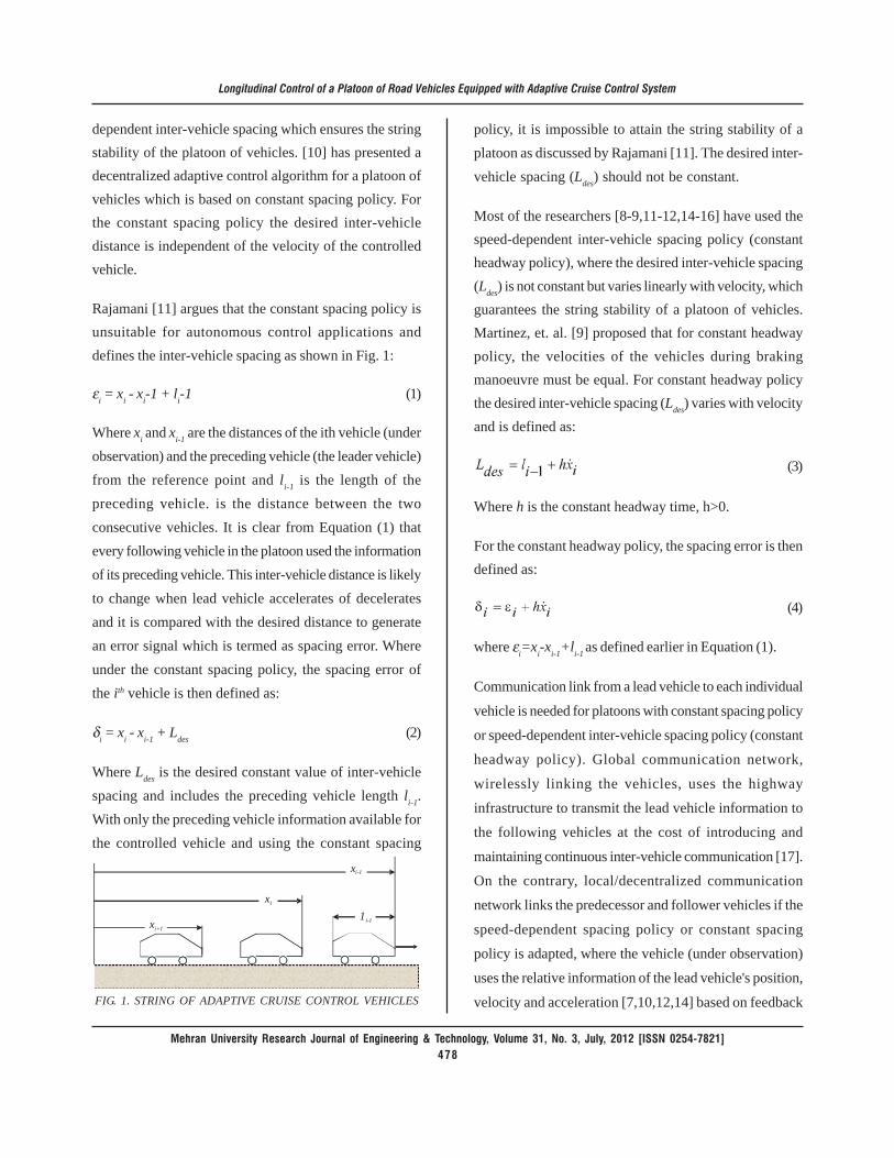
FIG. 1. STRING OF ADAPTIVE CRUISE CONTROL VEHICLES
policy, it is impossible to attain the string stability of aplatoon as discussed by Rajamani [11]. The desired inter-vehicle spacing (Ldes) should not be constant.
Most of the researchers [8-9,11-12,14-16] have used thespeed-dependent inter-vehicle spacing policy (constantheadway policy), where the desired inter-vehicle spacing(Ldes) is not constant but varies linearly with velocity, whichguarantees the string stability of a platoon of vehicles.Martinez, et. al. [9] proposed that for constant headwaypolicy, the velocities of the vehicles during brakingmanoeuvre must be equal. For constant headway policythe desired inter-vehicle spacing (Ldes) varies with velocityand is defined as:
(3)
Where h is the constant headway time, h>0.
For the constant headway policy, the spacing error is thendefined as:
(4)
where εi=xi-xi-1+li-1 as defined earlier in Equation (1).
Communication link from a lead vehicle to each individual
vehicle is needed for platoons with constant spacing policy
or speed-dependent inter-vehicle spacing policy (constant
headway policy). Global communication network,
wirelessly linking the vehicles, uses the highway
infrastructure to transmit the lead vehicle information to
the following vehicles at the cost of introducing and
maintaining continuous inter-vehicle communication [17].
On the contrary, local/decentralized communication
network links the predecessor and follower vehicles if the
speed-dependent spacing policy or constant spacing
policy is adapted, where the vehicle (under observation)
uses the relative information of the lead vehicle's position,
velocity and acceleration [7,10,12,14] based on feedback
dependent inter-vehicle spacing which ensures the stringstability of the platoon of vehicles. [10] has presented adecentralized adaptive control algorithm for a platoon ofvehicles which is based on constant spacing policy. Forthe constant spacing policy the desired inter-vehicledistance is independent of the velocity of the controlledvehicle.
Rajamani [11] argues that the constant spacing policy isunsuitable for autonomous control applications anddefines the inter-vehicle spacing as shown in Fig. 1:
εi = xi - xi-1 + li-1 (1)
Where xi and xi-1 are the distances of the ith vehicle (underobservation) and the preceding vehicle (the leader vehicle)from the reference point and li-1 is the length of thepreceding vehicle. is the distance between the twoconsecutive vehicles. It is clear from Equation (1) thatevery following vehicle in the platoon used the informationof its preceding vehicle. This inter-vehicle distance is likelyto change when lead vehicle accelerates of deceleratesand it is compared with the desired distance to generatean error signal which is termed as spacing error. Whereunder the constant spacing policy, the spacing error ofthe ith vehicle is then defined as:
δi = xi - xi-1 + Ldes (2)
Where Ldes is the desired constant value of inter-vehiclespacing and includes the preceding vehicle length li-1.With only the preceding vehicle information available forthe controlled vehicle and using the constant spacing
xi
xi-1
xi+1
1i-1
Mehran University Research Journal of Engineering & Technology, Volume 31, No. 3, July, 2012 [ISSN 0254-7821]479
Longitudinal Control of a Platoon of Road Vehicles Equipped with Adaptive Cruise Control System
linearization. Global communication link, due to setting
the link between the lead vehicle and the following vehicle
through the highway infrastructure, can be avoided by
using the local communication network. Global
communication network causes the noise in the
measurement and inaccuracies in the performance of the
platoon and increases the cost of the operation.
In the literature, research work has been focused on theeffects of parametric uncertainties on the performance ofthe platoon. Shladover [17] has analysed the behaviourof controller in the presence of uncertainties in mass,aerodynamic drag coefficient, and rolling resistance. Inaddition of that, Shladover [17] has focused on the effectsof severe manoeuvres, rapid changes in acceleration andjerks, measurement noise and different vehicle propulsiondynamics (due to less responsive power-train anddynamics of internal combustion engine which includeboth first-order and transport lags). Shladover [17]suggested that the existing controller should be modifiedto compensate the effects of the above parametricuncertainties. Swaroop, et. al. [10] has investigated theeffect of uncertainties in mass of the vehicle,aerodynamic drag coefficient, rolling resistance, and theircombined effect on the performance of a platoon. Theircontroller design is based on simplified model which doesnot take account of the states associated with torqueconverter, manifold air dynamics, slip between the tireand the wheels, and the lag in delivering the desiredbrake torque. Their analysis shows that the estimatedparameters do not converge to their true values becausethey have neglected the above state variables in theircontroller model. There is enough room to improve thestability of a platoon under these parametric uncertaintiescoupled with the above state variables effects in thecontroller design. Yi, et. al. [7] proposed the impedancecontrol algorithm, which is quite efficient and stable, andshows the robustness and stability of the vehicle platoonperformance against the uncertainties in vehicle model
parameters and the noise in the measurement signals.Sun et. al. [16] have estimated the parameters for thevehicles which can improve the string stability of theplatoon and have discussed the parametric uncertaintiesdue to varying road conditions like weather changes orroad gradients. This may seriously affect the performanceof the platoon. Their designed controller maintains thedesired performance under the influence of parametricuncertainties. Their designed model only simulates thebehaviour of platoon for the steady state operation butdoes not analyse the platoon in the emergency condition.Also, they have designed the controller for fixedparametric values but if the vehicle parameter change, asthe mass of the vehicle is variable with the number ofpassengers, the aerodynamic drag coefficient could bedifferent and the important thing is the severe weathercondition like heavy rain. Their model is not suitable forthese variable conditions. There is room for designing acontroller which can cope with large changes in theseparameters. Canudas, et. al. [13] referred the problem ofdesigning safe controllers for the internal dynamics ofthe platoon as the objective for future work.
This paper presents a control law, based on PID feedbackcontrol algorithm, for a constant inter-vehicle spacing ofthe vehicles of the platoon and investigates the effects ofnoise signal and sudden acceleration and braking in severeconditions on the performance of the platoon.
The paper is organised as follows. In Section 2 ACC systemwith its performance limitations are discussed and thestability conditions for individual vehicle stability andstring stability of the platoon are discussed. Section 3presents a simple longitudinal dynamics model for a membervehicle of the platoon and introduces a control law forlead vehicle. Performance of lead vehicle under theinfluence of noise signal is also shown in this section.Section 4 presents the control law for follower vehicle andinvestigates the behaviour of 2-vehicle and 6-vehicleplatoons in the presence of noise signal and large

Mehran University Research Journal of Engineering & Technology, Volume 31, No. 3, July, 2012 [ISSN 0254-7821]480
Longitudinal Control of a Platoon of Road Vehicles Equipped with Adaptive Cruise Control System
acceleration and deceleration. Section 5 discusses thesimulation results. Section 6 provides the conclusions andSection 7 highlights the directions for future research.
2. ACC SYSTEM AND ITSPERFORMANCE LIMITATIONS
An ACC system is the modified form of a standard cruisecontrol system. A cruise control system is used for thespeed control of a vehicle when the driver sets the vehicleat desired speed and vehicle travel under the cruise controlsystem. As the brake is applied the cruise control isdisconnected and control comes back in the driver control.An ACC vehicle is equipped with radar or any other sensorto measure the distance from the preceding vehicle. Whenthere is no preceding vehicle, ACC vehicle moves with theuser set speed and when it detects a preceding vehicle,ACC vehicle follows the preceding vehicle while trackingthe velocity trajectory of preceding vehicle andmaintaining a safe distance from preceding vehicle. ACCvehicle does not require any wireless communication fromother vehicles on the highway, it just reads the informationof the relative displacement, relative velocity and relativeacceleration of the preceding vehicle through the sensoror radar. ACC is an autonomous system.
ACC vehicle has two modes of steady state operation.
(1) Speed control
(2) Vehicle following control (space control)
In the speed control mode, much like a cruise controlsystem, ACC vehicle travels at user set speed. In thevehicle following mode, ACC vehicle maintains a desiredspacing from the preceding vehicle. ACC control thethrottle and brake to maintain that desired distance. Thissection mainly discusses the vehicle following mode ofthe ACC system and the need for transition trajectoriesfor the smooth transition from speed control mode tovehicle following mode and vice-versa. The vehicle
following mode must meet the two important performancecriterions. The performance criterions are the individualvehicle stability and the string stability of the platoon.
2.1 Individual Vehicle Stability
Individual vehicle stability is the ability of any membervehicle in the platoon to track any bounded accelerationand velocity profile of its predecessor with boundedspacing and velocity errors [11].
2.2 String Stability
String stability of a string of vehicles refers to a propertyin which spacing errors are guaranteed not to amplify asthey propagate towards the tail of the string [10,11,15,16].It is desired that the errors in spacing and velocity mustnot amplify upstream from one vehicle to another, i.e.spacing error between second and third vehicle shouldnot propagate to other member vehicles and so on. Stringstability ensures that spacing error decreases as theypropagate downstream through the platoon [12]. Whenthe preceding vehicle accelerates or decelerates then thespacing error would become non-zero, it is essential thento know that how the spacing error would propagate fromvehicle to vehicle in a string of ACC vehicles that use thesame spacing policy and control law. It is important for thestring stability that the spacing errors of successivevehicles should be independent of each other [11].
ACC is an autonomous control strategy. When a constantspacing policy is adapted, ACC vehicle satisfies theindividual vehicle stability condition but the string stabilitycondition is not satisfied with constant spacing policy.Rajamani [11] has analysed that the constant spacing policyis unsuitable for autonomous control operations.Therefore, a constant time-gap (constant headway) policyshould be adapted for ACC systems where the desiredinter-vehicle distance is not constant but varies linearlywith ACC vehicle velocity.
Mehran University Research Journal of Engineering & Technology, Volume 31, No. 3, July, 2012 [ISSN 0254-7821]481
Longitudinal Control of a Platoon of Road Vehicles Equipped with Adaptive Cruise Control System
Consider the situation when the ACC vehicle operatesunder the speed control mode and it detects a slow ordecelerating target vehicle ahead of it. ACC vehicle willaccelerate first to get to the desired distance and by thetime ACC vehicle will acquire the high acceleration whilethe target vehicle is decelerating. As the ACC vehiclereaches the desired distance quickly and decides todecelerate when the actual distance is less than the desireddistance. At this moment, even the maximum braking forceis applied, it will be difficult to avoid the collision.Therefore, a transitional trajectory [11] must be designedfor the steady state following distance during the transitionfrom speed control mode to vehicle following mode andvice-versa.
The main reasons for the transition trajectory are:
(1) To avoid/prevent collision.
(2) The brake and engine actuators have limitedallowable forces and they saturate.
(3) Whether a new detected vehicle should alwaysbe the target vehicle for ACC vehicle or not.
When a new vehicle is encountered, then the ACC vehiclehas to decide:
(1) The ACC vehicle should use the speed controlmode.
(2) The ACC vehicle should use the vehicle followingmode.
(3) The ACC vehicle should brake as hard aspossible to prevent collision.
For the transitional controller design, a range-rang ratecan be used to make the above decisions [11]. Themanoeuvres controlled by transitional controller do notaffect the string stability of the platoon. They only control
the lead vehicle, the rest of the platoon follow the samecontrol law to maintain the string stability.
3. A SIMPLE MODEL OF A MEMBER-VEHICLE OF THE PLATOON
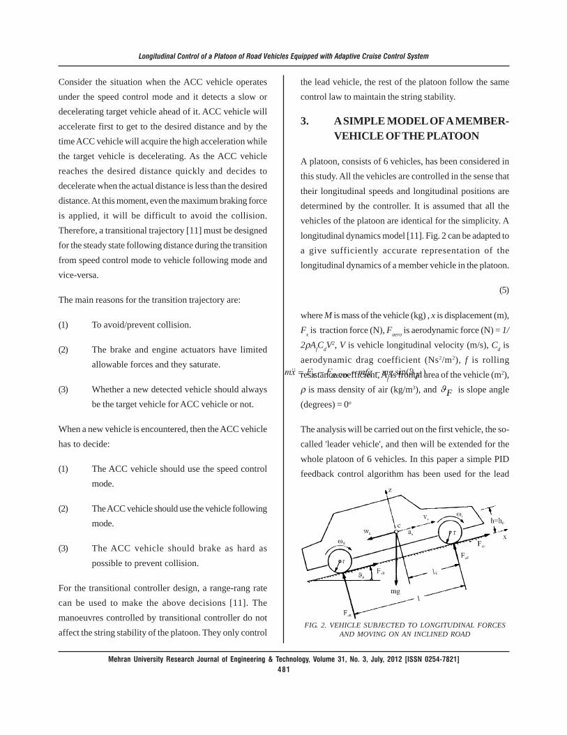
A platoon, consists of 6 vehicles, has been considered inthis study. All the vehicles are controlled in the sense thattheir longitudinal speeds and longitudinal positions aredetermined by the controller. It is assumed that all thevehicles of the platoon are identical for the simplicity. Alongitudinal dynamics model [11]. Fig. 2 can be adapted toa give sufficiently accurate representation of thelongitudinal dynamics of a member vehicle in the platoon.
(5)
where M is mass of the vehicle (kg) , x is displacement (m),Fx is traction force (N), Faero is aerodynamic force (N) = 1/2ρAfCdV
2, V is vehicle longitudinal velocity (m/s), Cd isaerodynamic drag coefficient (Ns2/m2), f is rollingresistance coefficient, Af is frontal area of the vehicle (m2),ρ is mass density of air (kg/m3), and Fϑ is slope angle(degrees) = 0o
The analysis will be carried out on the first vehicle, the so-called 'leader vehicle', and then will be extended for thewhole platoon of 6 vehicles. In this paper a simple PIDfeedback control algorithm has been used for the lead
FIG. 2. VEHICLE SUBJECTED TO LONGITUDINAL FORCESAND MOVING ON AN INCLINED ROAD

Mehran University Research Journal of Engineering & Technology, Volume 31, No. 3, July, 2012 [ISSN 0254-7821]482
Longitudinal Control of a Platoon of Road Vehicles Equipped with Adaptive Cruise Control System
vehicle, where the only feedback signal is the actualvelocity of the lead vehicle. The block diagram for feedbackcontrol system is shown in Fig. 3.
The control signal is Fx, the traction force at the contactpoint between the tire and the ground.
(6)
where Vd=5 m/s is the desired velocity of the lead vehicleand Kp=3000 is the proportional gain, Ki=800 in theintegral gain and Kd=500 is the derivative gain.
For the design of any controller, it is important to knowabout the transient and steady state behaviour of thesystem. The control strategy, PID controller, used for leadvehicle, in Fig. 4 (a-b), shows that the transient behaviourof the lead vehicle dies away quickly with a little oscillationand the lead vehicle attains the steady state position withina short time. This shows the stability in the designedcontroller.
The simulation is carried out when the lead vehicle issubjected to the noise signal. The possible causes forthe noise are gust of air, noise in the measurement signal,uncertainty in the traction force due to time delays,weather condition, actuation lags, sensing lags or anyother disturbance. In this study the source of noise isthe disturbance in the input force and it is assumed to be300 N between 25-27 seconds and 400 N between 45-47seconds as shown in Fig. 5. The controller is quite stablefor the lead vehicle in the presence of the noise signal.The desired velocity for the lead vehicle is 5m/s. The
mass of all the vehicles is 1200 kg, aerodynamic dragcoefficient is 0.3 and the coefficient of rolling resistanceis 0.01.
4. EFFECT OF NOISE SIGNAL ANDACCELERATION VARIATION ONTHE PERFORMANCE OFPLATOON
This section discusses the performance of 2-vehicle and6-vehicle platoon under the influence of noise signal andlarge acceleration and deceleration. A numerical simulationhas been conducted for the designed controller.
FIG. 3. BLOCK DIAGRAM FOR THE PID FEEDBACKCONTROL SYSTEM
5.5
5
4.5
4
3.5
3
2.5
2
1.50 10 20 30 40 50 60
Long
itudi
nal V
eloc
ity (m
/s)
Time (s)
FIG. 4(a). VELOCITY OF THE LEAD VEHICLE
FIG. 4(b). ACCELERATION OF THE LEAD VEHICLEWITHOUT NOISE
Mehran University Research Journal of Engineering & Technology, Volume 31, No. 3, July, 2012 [ISSN 0254-7821]483
Longitudinal Control of a Platoon of Road Vehicles Equipped with Adaptive Cruise Control System
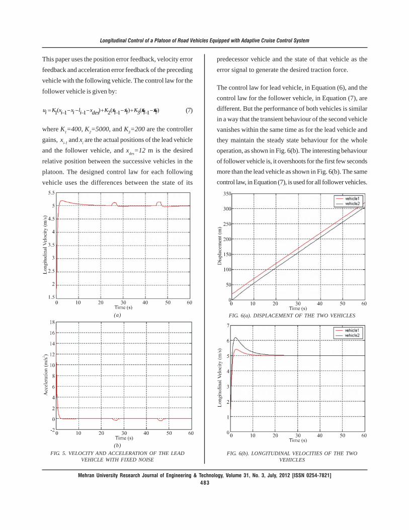
This paper uses the position error feedback, velocity errorfeedback and acceleration error feedback of the precedingvehicle with the following vehicle. The control law for thefollower vehicle is given by:
)1(3)1(2)11(1 ixixKixixKdesxilixixKiu &&&&&& −−+−−+−−−−−= (7)
where K1=400, K2=5000, and K3=200 are the controllergains, xi-1 and xi are the actual positions of the lead vehicleand the follower vehicle, and xdes=12 m is the desiredrelative position between the successive vehicles in theplatoon. The designed control law for each followingvehicle uses the differences between the state of its
predecessor vehicle and the state of that vehicle as theerror signal to generate the desired traction force.
The control law for lead vehicle, in Equation (6), and thecontrol law for the follower vehicle, in Equation (7), aredifferent. But the performance of both vehicles is similarin a way that the transient behaviour of the second vehiclevanishes within the same time as for the lead vehicle andthey maintain the steady state behaviour for the wholeoperation, as shown in Fig. 6(b). The interesting behaviourof follower vehicle is, it overshoots for the first few secondsmore than the lead vehicle as shown in Fig. 6(b). The samecontrol law, in Equation (7), is used for all follower vehicles.
(a)
(b)FIG. 5. VELOCITY AND ACCELERATION OF THE LEAD
VEHICLE WITH FIXED NOISE
FIG. 6(a). DISPLACEMENT OF THE TWO VEHICLES
FIG. 6(b). LONGITUDINAL VELOCITIES OF THE TWOVEHICLES
Mehran University Research Journal of Engineering & Technology, Volume 31, No. 3, July, 2012 [ISSN 0254-7821]484
Longitudinal Control of a Platoon of Road Vehicles Equipped with Adaptive Cruise Control System
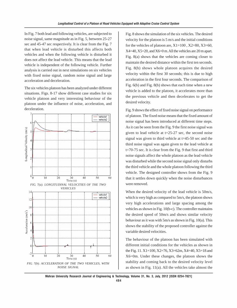
In Fig. 7 both lead and following vehicles, are subjected tonoise signal, same magnitude as in Fig. 5, between 25-27sec and 45-47 sec respectively. It is clear from the Fig. 7that when lead vehicle is disturbed this affects bothvehicles and when the following vehicle is disturbed itdoes not affect the lead vehicle. This means that the leadvehicle is independent of the following vehicle. Furtheranalysis is carried out in next simulations on six vehicleswith fixed noise signal, random noise signal and largeacceleration and deceleration.
The six vehicles platoon has been analyzed under differentsituations. Figs. 8-17 show different case studies for sixvehicle platoon and very interesting behaviour of theplatoon under the influence of noise, acceleration, anddeceleration.
Fig. 8 shows the simulation of the six vehicles. The desiredvelocity for the platoon is 5 m/s and the initial conditionsfor the vehicles of platoon are, X1=100 , X2=80, X3=60,X4=40, X5=20, and X6=0 m. All the vehicles are 20 m apart.Fig. 8(a) shows that the vehicles are coming closer tomaintain the desired distance within the first ten seconds.Fig. 8(b) shows whole platoon acquires the desiredvelocity within the first 30 seconds; this is due to highacceleration in the first four seconds. The comparison ofFig. 6(b) and Fig. 8(b) shows that each time when a newvehicle is added to the platoon, it accelerates more thanthe previous vehicle and then decelerates to get thedesired velocity.
Fig. 9 shows the effect of fixed noise signal on performanceof platoon. The fixed noise means that the fixed amount ofnoise signal has been introduced at different time steps.As it can be seen from the Fig. 9 the first noise signal wasgiven to lead vehicle at t=25-27 sec, the second noisesignal was given to third vehicle at t=45-50 sec and thethird noise signal was again given to the lead vehicle att=70-75 sec. It is clear from the Fig. 9 that first and thirdnoise signals affect the whole platoon as the lead vehiclewas disturbed while the second noise signal only disturbsthe third vehicle and the whole platoon following the thirdvehicle. The designed controller shows from the Fig. 9that it settles down quickly when the noise disturbanceswere removed.
When the desired velocity of the lead vehicle is 50m/s,which is very high as compared to 5m/s, the platoon showsvery high accelerations and large spacing among thevehicles as shown in Fig. 10(b-c). The controller maintainsthe desired speed of 50m/s and shows similar velocitybehaviour as it was with 5m/s as shown in Fig. 10(a). Thisshows the stability of the proposed controller against thevariable desired velocities.
The behaviour of the platoon has been simulated withdifferent initial conditions for the vehicles as shown inthe Fig. 11. X1=100, X2=76, X3=62m, X4=40, X5=18 andX6=0m. Under these changes, the platoon shows thestability and coming back to the desired velocity levelas shown in Fig. 11(a). All the vehicles take almost the
FIG. 7(a). LONGITUDINAL VELOCITIES OF THE TWOVEHICLES
FIG. 7(b). ACCELERATION OF THE TWO VEHICLES, WITHNOISE SIGNAL

Mehran University Research Journal of Engineering & Technology, Volume 31, No. 3, July, 2012 [ISSN 0254-7821]485
Longitudinal Control of a Platoon of Road Vehicles Equipped with Adaptive Cruise Control System
same time to reach the steady state position whencompared with uniform initial inter-vehicle distances.This shows the robustness of the proposed controlleragainst these changes. Fig. 11(a) (non-uniform initialinter-vehicle distances) is compared with Fig. 8(b)(uniform initial inter-vehicle distances), it can be seenthat vehicle 2 accelerates more in Fig. 11(a) as comparedto Fig. 8(b) because vehicle 2 is more distant from vehicle1, X1-X2=24m. Fig. 12. shows the performance of platoonwhen lead vehicle is subjected to random noise. In thepresence of random noise, the transient and steady-statebehaviours of the platoon are hardly affected and theplatoon is trying to maintain the desired velocity duringthe steady-state operation
Fig. 13 shows a very interesting behaviour of the platoonwhen the brake is applied on the third vehicle for the timespan of 35-40 seconds. The brake affects the whole platoonfollowing the third vehicle but it does not affect the firsttwo vehicles. Fig. 13(a) shows that the velocity of theremaining four vehicles is reduced during the same timespan and the vehicles decelerate first during the brakeand when the brake is removed vehicles accelerate quicklyto acquire the required velocity as shown in Fig. 13(b).The spacing among the vehicles increases when the brakeis applied but it settles down when the brake is removedas shown in Fig. 13(c). This shows quite stable behaviourof the platoon.
FIG. 8(a). INTER-VEHICLE DISTANCES OF 6 VEHICLES
FIG. 8(b). LONGITUDINAL VELOCITIES OF 6 VEHICLES
FIG. 8(c). ACCELERATIONS OF 6 VEHICLES
FIG. 8(d). VEHICLES SPACING, WITHOUT NOISE SIGNALAND UNIFORM SPACING BETWEEN THE VEHICLES

Mehran University Research Journal of Engineering & Technology, Volume 31, No. 3, July, 2012 [ISSN 0254-7821]486
Longitudinal Control of a Platoon of Road Vehicles Equipped with Adaptive Cruise Control System
FIG. 9(a). LONGITUDINAL VELOCITIES OF 6 VEHICLES
FIG. 9(b). ACCELERATIONS OF 6 VEHICLES
FIG. 9(c). VEHICLES SPACING, WITH FIXED NOISE SIGNALAND UNIFORM SPACING BETWEEN THE VEHICLES
FIG. 10(a). LONGITUDINAL VELOCITIES OF 6 VEHICLES
FIG. 10(b). ACCELERATIONS OF 6 VEHICLES
FIG. 10(c). VEHICLES SPACING, AT DESIRED VELOCITY50m/s AND UNIFORM SPACING BETWEEN THE VEHICLES

Mehran University Research Journal of Engineering & Technology, Volume 31, No. 3, July, 2012 [ISSN 0254-7821]487
Longitudinal Control of a Platoon of Road Vehicles Equipped with Adaptive Cruise Control System
One important fact can be seen from the above Fig. 13that the 4th, 5th, and 6th vehicles do not need theinformation of the lead vehicle. Each following vehicleuses the information of its preceding vehicle only.Suppose there is large platoon and every followingvehicle needs the information of its preceding and leadvehicles then there would be large communicationdelays of information for the following vehicles in thetail. Therefore, it is worth understanding that anyfollowing vehicle should use the information of itspreceding vehicle only or the information of itspreceding vehicle and its following vehicle or the
information of its preceding vehicle and the leadvehicle.
Consider the condition when the platoon is moving at aconstant velocity and the lead vehicle suddenly executesan acceleration manoeuvre. The acceleration in the leadvehicle causes the whole platoon to accelerate and thespacing among the vehicles is likely to increase and similarbehaviour is shown in Fig. 14(a-c). This accelerationcreates a lot of oscillations in the control input commandof each vehicle of the platoon. The platoon is comingback to the desired velocity when the acceleration isremoved.
FIG. 11(a). LONGITUDINAL VELOCITIES OF 6 VEHICLES
FIG. 11(b). VEHICLES SPACING, NON-UNIFORM SPACINGBETWEEN THE VEHICLES
FIG. 12(b). VEHICLES SPACING, WHEN LEAD VEHICLE ISSUBJECTED TO RANDOM NOISE
FIG. 12(a). LONGITUDINAL VELOCITIES OF 6 VEHICLES

Mehran University Research Journal of Engineering & Technology, Volume 31, No. 3, July, 2012 [ISSN 0254-7821]488
Longitudinal Control of a Platoon of Road Vehicles Equipped with Adaptive Cruise Control System
FIG. 13(a). LONGITUDINAL VELOCITIES OF 6 VEHICLES
FIG. 13(b). ACCELERATIONS OF 6 VEHICLES
FIG. 13(c). VEHICLES SPACING, AT DESIRED VELOCITY 5m/sAND WHEN THE BRAKE IS APPLIED ON VEHICLE 3 FOR
t=35 TO 40 SEC
FIG. 14(a). LONGITUDINAL VELOCITIES OF 6 VEHICLES
FIG. 14(b). ACCELERATIONS OF 6 VEHICLES
FIG. 14(c). VEHICLES SPACING, AT DESIRED VELOCITY 5m/sAND WHEN THE LEAD VEHICLE IS ACCELERATED

Mehran University Research Journal of Engineering & Technology, Volume 31, No. 3, July, 2012 [ISSN 0254-7821]489
Longitudinal Control of a Platoon of Road Vehicles Equipped with Adaptive Cruise Control System
Consider the condition when the platoon in moving at aconstant velocity and suddenly the lead vehicle executesa deceleration manoeuvre. The deceleration of the leadvehicle causes the whole platoon to decelerate and thespacing among the vehicles is likely to decrease and similarbehaviour is shown in Fig.15(a-c). The platoon is comingback to the desired velocity when the deceleration isremoved.
Fig. 16 shows the performance of the platoon when theplatoon is moving on a slope with the slope angle of 10degrees. The velocities of the vehicle and the spacingamong the vehicles decrease due to the slope but theacceleration increases to maintain the desired velocity andspacing as shown in Fig. 16(b).
Fig. 17 shows a very important feature of the platoon whenthe brakes are applied to stop the vehicle. The platoonstarts with the initial conditions and acquires the desiredvelocity of 5 m/s and then at t=60 sec brake is applied onlead vehicle to stop the platoon. The displacement of allvehicles, the velocity of all vehicles, the acceleration of allvehicles, and the spacing of all vehicles can be seen inFig. 17(a-d) respectively. The velocities reduce quicklywithin ten seconds of brakes and there is a largedeceleration in the vehicles of platoon to reduce the speed,the spacing reduces within the same time when the brakeis applied and then comes back to safe level.
For simplicity only six vehicles were considered for thesimulation in this study as it is difficult to view the graphsif more vehicles are included in the platoon. Figs. 18-19shows the simulation of ten vehicles under normalsituation which is very similar to Fig. 8.
Initially all the ten vehicles in Fig. 18 are 20 m apart. It canbe seen from the Fig. 18 that all the following vehicles arecoming closer in the first few seconds to reach the desiredinter-vehicle distance; this is the transient response ofthe platoon and taking very short time to disappear. Theplatoon is showing very stable behaviour in the steadystate condition. The results of the above simulation are
FIG. 15(a). LONGITUDINAL VELOCITIES OF 6 VEHICLES
FIG. 15(b). ACCELERATIONS OF 6 VEHICLES
FIG. 15(c). VEHICLES SPACING, AT DESIRED VELOCITY 5m/sAND WHEN THE BRAKE IS APPLIED ON THE LEAD VEHICLE

Mehran University Research Journal of Engineering & Technology, Volume 31, No. 3, July, 2012 [ISSN 0254-7821]490
Longitudinal Control of a Platoon of Road Vehicles Equipped with Adaptive Cruise Control System
FIG. 16(a). LONGITUDINAL VELOCITIES OF 6 VEHICLES
FIG. 16(b). ACCELERATIONS OF 6 VEHICLES
FIG. 16(c). VEHICLES SPACING, AT DESIRED VELOCITY 5m/sAND WHEN THE PLATOON IN MOVING ON A SLOPE WITH
THE SLOPE ANGEL OF 10 DEGREES
discussed in comparison with the previous models in theSection 5. The limitations and shortcomings of theproposed PID feedback control algorithm will be observedin Section 6 and the alternate control algorithm will besuggested in the Section 7.
5. SIMULATION RESULT
Simulations are performed for lead vehicle, 2-vehicle and6-vehicle platoons. Fig. 4 shows the stable PID feedbackcontroller for the lead vehicle. The result shows that thelead vehicle (vehicle 1) achieves the desired velocity withzero steady state error. Fig. 5 shows the effect of noisesignal on the lead vehicle (vehicle 1) performance. The
FIG. 17(a). INTER-VEHICLE DISTANCES OF 6 VEHICLES
FIG. 17(b). LONGITUDINAL VELOCITIES OF 6 VEHICLES
Mehran University Research Journal of Engineering & Technology, Volume 31, No. 3, July, 2012 [ISSN 0254-7821]491
Longitudinal Control of a Platoon of Road Vehicles Equipped with Adaptive Cruise Control System
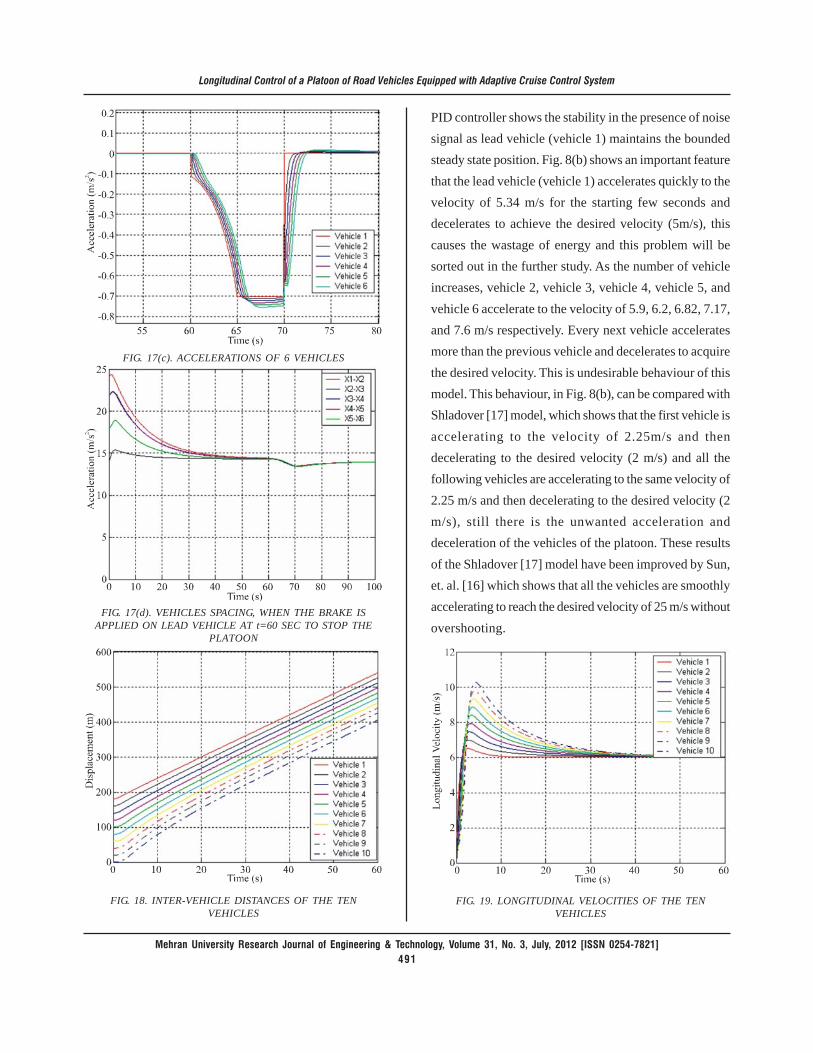
FIG. 17(c). ACCELERATIONS OF 6 VEHICLES
FIG. 17(d). VEHICLES SPACING, WHEN THE BRAKE ISAPPLIED ON LEAD VEHICLE AT t=60 SEC TO STOP THE
PLATOON
PID controller shows the stability in the presence of noisesignal as lead vehicle (vehicle 1) maintains the boundedsteady state position. Fig. 8(b) shows an important featurethat the lead vehicle (vehicle 1) accelerates quickly to thevelocity of 5.34 m/s for the starting few seconds anddecelerates to achieve the desired velocity (5m/s), thiscauses the wastage of energy and this problem will besorted out in the further study. As the number of vehicleincreases, vehicle 2, vehicle 3, vehicle 4, vehicle 5, andvehicle 6 accelerate to the velocity of 5.9, 6.2, 6.82, 7.17,and 7.6 m/s respectively. Every next vehicle acceleratesmore than the previous vehicle and decelerates to acquirethe desired velocity. This is undesirable behaviour of thismodel. This behaviour, in Fig. 8(b), can be compared withShladover [17] model, which shows that the first vehicle isaccelerating to the velocity of 2.25m/s and thendecelerating to the desired velocity (2 m/s) and all thefollowing vehicles are accelerating to the same velocity of2.25 m/s and then decelerating to the desired velocity (2m/s), still there is the unwanted acceleration anddeceleration of the vehicles of the platoon. These resultsof the Shladover [17] model have been improved by Sun,et. al. [16] which shows that all the vehicles are smoothlyaccelerating to reach the desired velocity of 25 m/s withoutovershooting.
FIG. 18. INTER-VEHICLE DISTANCES OF THE TENVEHICLES
FIG. 19. LONGITUDINAL VELOCITIES OF THE TENVEHICLES

Mehran University Research Journal of Engineering & Technology, Volume 31, No. 3, July, 2012 [ISSN 0254-7821]492
Longitudinal Control of a Platoon of Road Vehicles Equipped with Adaptive Cruise Control System
Once the platoon acquires the steady-state condition thenit shows very stable behaviour under the changes inacceleration and deceleration and in the presence of noisesignal. The designed controller shows the robustnessagainst the different noise signal, against the largevariation in the initial conditions, against large variationin acceleration and deceleration and when the platoon istravelling on a slope and these all can be seen in Section 4simulations. The behaviour of acceleration of six vehicles,Fig. 8(c), is quite similar to Shladover [17] model but thevehicles should reach the desired velocity smoothly andshould not start with the high acceleration. The comparisonof Fig. 8(c) with Sun, et. al. [16] shows that the maximumstarting acceleration for the proposed model is 12.3 m/s2
which is practically unsuitable and maximum startingacceleration for the Sun, et al .[16] is 2.5 m/s2, even thedesired velocity (25m/s) in the Sun et al [16] model is muchgreater than the proposed model desired velocity (5 m/s).
The simulation results of Figs. 14-15, and 17 can becompared with Shladover [17] for the changes inacceleration and deceleration commands and shows quitesimilar behaviour to Shladover [17] model. But both modelsare not suitable because they do not consider theactuation lags in their designed controllers.
The simulation result of Fig. 12(b) can be compared withthe Figs. 7-5 [11]. The spacing errors in Fig. 12(b) deviateswithin the range of 14.37-14.27m in the presence of noisesignal and Figs. 7-5 [11] shows the deviation of 6.7-6.27m.The platoons performances in both figures are similar butdeviation in Fig. 12(b) is small. This is because themagnitude for the considered random noise signal is verysmall as compared to Figs. 7-5 [11].
The reasons for the above shortcomings in the proposedPID controller are following. The proposed model doesnot consider the non-linearity in the system. This modeluses the constant spacing policy, while for a smooth
execution of acceleration manoeuvre constant headwaypolicy should be employed in this model. The essentialfeature is the control signal, to drive the vehicles to desiredsafe distance and required velocity, which should bechosen using the sliding mode control method which isused by most of the researchers in the literature. The actualspacing between the vehicles achieved by the proposedcontroller is 14.3m while the desired spacing between thevehicles is 12m, therefore, the designed model is notcapable to keep the desired distance, the reason is; in thismodel the vehicles are dynamically coupled and the modeldoes not consider the spacing error dynamics, this alsocan cause the string instability. The consideration ofspacing error dynamics is essential to control the vehiclesat desired distance. The time delays in the signalprocessing and actuation signals have been neglectedand the controller gains have not been selected by usingan appropriate technical method.
The above results also satisfy the results of [1] and showsthe limitations of PID controller when compared withShladover [17] and Sun, et. al. [16]. Due to incapability ofthe PID controller, to cope with the complicated non-linearmodels PID controllers should be replaced by moreadvanced controllers and these advanced controllers arediscussed in Section 7.
6. CONCLUSIONS
In this paper, a simple PID feedback control algorithmshave been designed for the lead vehicle and the followingvehicle. The proposed controller is giving stable behaviourin terms of transient and steady-state behaviour. Theperformance of the platoon, in the presence of noise signaland large changes in acceleration and deceleration, havealso been investigated. The designed PID feedbackcontroller is quite stable once the steady-state behaviouris achieved and shows good agreement with the boundedvelocity and bounded spacing error.
Mehran University Research Journal of Engineering & Technology, Volume 31, No. 3, July, 2012 [ISSN 0254-7821]493
Longitudinal Control of a Platoon of Road Vehicles Equipped with Adaptive Cruise Control System
As the designed model is based on the constant spacingpolicy, therefore, it is not suitable for autonomousoperation. Because only the relative information of thepreceding vehicle have been used for the control law forthe following vehicle which is not enough for the stringstability when the constant spacing policy is used. For aconstant spacing policy, more information is required forthe controlled vehicle and this adds more communicationload. The results show that there is an undesired behaviourof the acceleration of each individual following vehicle toreach the desired velocity. This is because the time delaysin actuation and sensing have been neglected and alsothis is due to the fact that the design of the controller isbased on a simplified model and used the PID controlstrategy which is very simple and cannot be adapted forthe control of a ACC vehicle platoon. The designed controllaw for each following vehicle uses the differences betweenthe state of its predecessor vehicle and the state of thatvehicle as the error signal generates the desired tractionforce. The only information of the predecessor vehicle forthe controlled vehicle is not enough to ensure the stringstability of the platoon. The information of the precedingvehicle with the information of the lead vehicle and spacingerror dynamics are necessary to be included in the controllaw for the safe control of the platoon and with ensuredstring stability. The control law in Equation (7) is used tocalculate the differences in states of predecessor vehicleand the controlled vehicle and the same control law isused for all the following vehicles. It has been observedthrough this study that PID feedback control strategy isnot suitable for the longitudinal control of the platoonand should be replaced be advanced controllers, asdiscussed in Section 5.
7. FUTURE WORK
To improve the controller design, an advanced controlstrategy is required. The controller should have thecapability to cope with the spacing error dynamics andshould take into account of the signal processing lagsand internal actuation lags. The advanced controllers
which can make the model more realistic are Adaptivecontroller, sliding mode control method, predictivecontroller, switching mode controller or transitionalcontroller and should be based on constant headway policyto maintain the safe distance among the vehicles of theplatoon.
The proposed PID controller should be replaced byintroducing the ACC system (autonomous control). TheACC, with sliding mode control method, should use theconstant headway policy where the spacing distance isnot constant but varies linearly with the velocity of thecontrolled vehicle. The conditions for string stabilityshould be analysed and guaranteed in the further study.And then the controller should be further modified byintroducing the transitional trajectories which helps insmooth switching between the different modes of ACC toavoid collisions while keeping the control on maximumallowable brake force for maximum possible deceleration.
The information available for the following vehicle controllaw is also very important. The proposed controller designcan be improved if the lead vehicle information could beavailable for all the following vehicles (requires globalcommunication network) in addition with the precedingvehicle information. This can increase the communicationload and highway infrastructure is needed to generate thelink between the lead vehicle and the following vehicles.The transmission of signals through this medium causesthe noise in the measurement and time delays in theoperation.
One other strategy discussed in the literature is to use theinformation of the state of the predecessor vehicle andthe follower vehicle for the vehicle under observation.This requires more devices at the rear of the vehicle andincreases the communication load, the calculation time,and noise in the measurement signal. Also, for a constantheadway policy the controller design using a sliding modecontrol method would be very complicated for such astrategy.
Mehran University Research Journal of Engineering & Technology, Volume 31, No. 3, July, 2012 [ISSN 0254-7821]494
Longitudinal Control of a Platoon of Road Vehicles Equipped with Adaptive Cruise Control System
It has been observed that the lead vehicle information isnecessary for all the following vehicles. It is necessary toinvestigate that whether the information of the precedingvehicle is useful along with the information of the leadvehicle. It should be noted that if the information of bothlead and preceding vehicles are used for the followingvehicle then it will result in communication delays.
ACKNOWLEDGMENTS
The authors would like to express their sincere thanks toMehran University of Engineering & Technology,Jamshoro, Pakistan, for giving them an opportunity topursue this study. The research work/study was supportedby Higher Education Commission, Govternment ofPakistan under Faculty Development Scheme.
REFERENCES
[1] Peppard, L.E., "String Stability of Relative-Motion PIDVehicle Control Systems", IEEE Transactions onAutomatic Control, Volume 19, No. 5, pp. 579-581,1974.
[2] Vlacic, L., Parent, M., and Harashima, F., "IntelligentVehicle Technologies", Oxford, Butterworth-Heinemann,2001.
[3] Swaroop, D., and Hedrick, J.K., "String Stability ofInterconnected Systems", IEEE Transactions onAutomatic Control, Volume 41, No. 3, pp. 349-356,1996.
[3] Swaroop, D., and Hedrick, J.K., "Constant SpacingStrategies of Platooning in Automated Highway Systems",Transactions of the ASME, Volume 121, pp. 462-470,1999.
[5] Huang, A.C., and Chen, Y.J., "Safe Platoon Control ofAutomated Highway Systems", Proceedings Institute ofMechancial Engineers Part-I, Volume 215, No. 5,pp. 531-543, 2001.
[6] Kato, S., Tsugawa, S., Tokuda, K., Matsui, T., and Fujii,H., "Vehicle Control Algorithms for Cooperative Drivingwith Automated Vehicles and IntervehicleCommunications", IEEE Transactions on IntelligentTransportation Systems, Volume 3, No. 3, pp. 155-161,2002.
[7] Yi, S.Y., and Chong, K.T., "Impedance Control for aVehicle Platoon System", Mechatronics, Volume 15,No. 5, pp. 627-638, 2005.
[8] Girard, A.R., Spry, S., and Hedrick, J.K., "IntelligentCruise-Control Applications", IEEE Robotics andAutomation Magazine, Volume 12, No. 1, pp. 22-28,2005.
[9] Martinez, J.J., and Canudas de Wit, C., "A SafeLongitudinal Control for Adaptive Cruise Control andStop-and-Go Scenarios", IEEE Transactions on ControlSystems Technology, 15, No. 2, pp. 246-258, 2007.
[10] Swaroop, D., Hedrick, J.K., and Choi, S.B., "DirectAdaptive Longitudinal Control of Vehicle Platoons",IEEE Transactions on Vehicular Technology, Volume50, No. 1, pp. 150-161, 2001.
[11] Rajamani, R., "Vehicle Dynamics and Control", NewYork, Springer. 2006.
[12] Ferrara, A., and Vecchio, C., "Collision AvoidanceStrategies and Coordinated Control of PassengerVehicles", Nonlinear Dynamics, Volume 49,pp. 475-492, 2007.
[13] Canudas de Wit, C., and Brogliato, B., "Stability Issuesfor Vehicle Platooning in Automated Highway Systems".Proceedings of the IEEE International Conference onControl Applicalions, Kohala Coast-Island of Hawai'i,Hawai'i, USA, 1999.
[14] Liang, C.Y., and Peng, H., "Optimal Adaptive CruiseControl with Guaranteed String Stability", Vehicle SystemDynamics, Volume 31, pp. 313-330, 1999.
[15] Rajamani, R., and Zhu, C., "Semi-Autonomous AdaptiveCruise Control Systems", IEEE Transactions on VehicularTechnology,Volume 51, No. 5, pp. 1186-1192, 2002.
[16] Sun, M., Lewis, F.L., and Ge, S.S., "Platoon-StableAdaptive Controller Design", 43rd IEEE Conference onDecision and Control, Atlantis, Paradise Island, Bahamas,2004.
[17] Shladover, S.E., "Longitudinal Control of AutomativeVehicles in Close-Formation Platoons", Journal ofDynamic Systems, Measurement, and Control,Volume 113, pp. 231-241, 1991.
[18] Ali, Z., Popov, A.A., and Charles, G., "TransitionController for Adaptive Cruise Control System", AVEC10, 10th International Symposium on Advanced VehicleControl. Loughborough, UK, 2010.