long-term field monitoring of paving fabric interlayer...
TRANSCRIPT
i
Long-Term Field Monitoring of Paving Fabric Interlayer
Systems to Reduce Reflective Cracking
FINAL REPORT
by
Farshad Amini & Kejun Wen
Department of Civil & Environmental Engineering
Jackson State University
In Cooperation with the
Mississippi Department of Transportation
Burns Cooley and Dennis, Inc.
and the
U.S. Department of Transportation
Federal Highway Administration
Jackson State University
Jackson, Mississippi
June 2016
i
Technical Report Documentation Page 1.Report No.
FHWA/MS-DOT-RD-16-184
2. Government Accession No.
3. Recipient’s Catalog No.
4. Title and Subtitle
Long-Term Field Monitoring of Paving Fabric Interlayer Systems
to Reduce Reflective Cracking
5. Report Date
June 2016 6. Performing Organization Code
MS-DOT-RD-16-184
7. Author(s)
Farshad Amini & Kejun Wen
8. Performing Organization Report No.
9. Performing Organization Name and Address
Department of Civil & Environmental Engineering
Jackson State University
1400 J. R. Lynch Street
P.O. Box 17068
Jackson, MS 39217-0168
10. Work Unit No. (TRAIS)
11. Contract or Grant No.
State Study 184
12. Sponsoring Agency Name and Address
Mississippi Department of Transportation
Research Division
P O Box 1850
Jackson, MS 39215-1850
13. Type Report and Period Covered
Final Report – October 2005 – June
2016 14. Sponsoring Agency Code
15. Supplementary Notes
Conducted in cooperation with the Mississippi Department of Transportation and the U.S. Department of
Transportation Federal Highway Administration
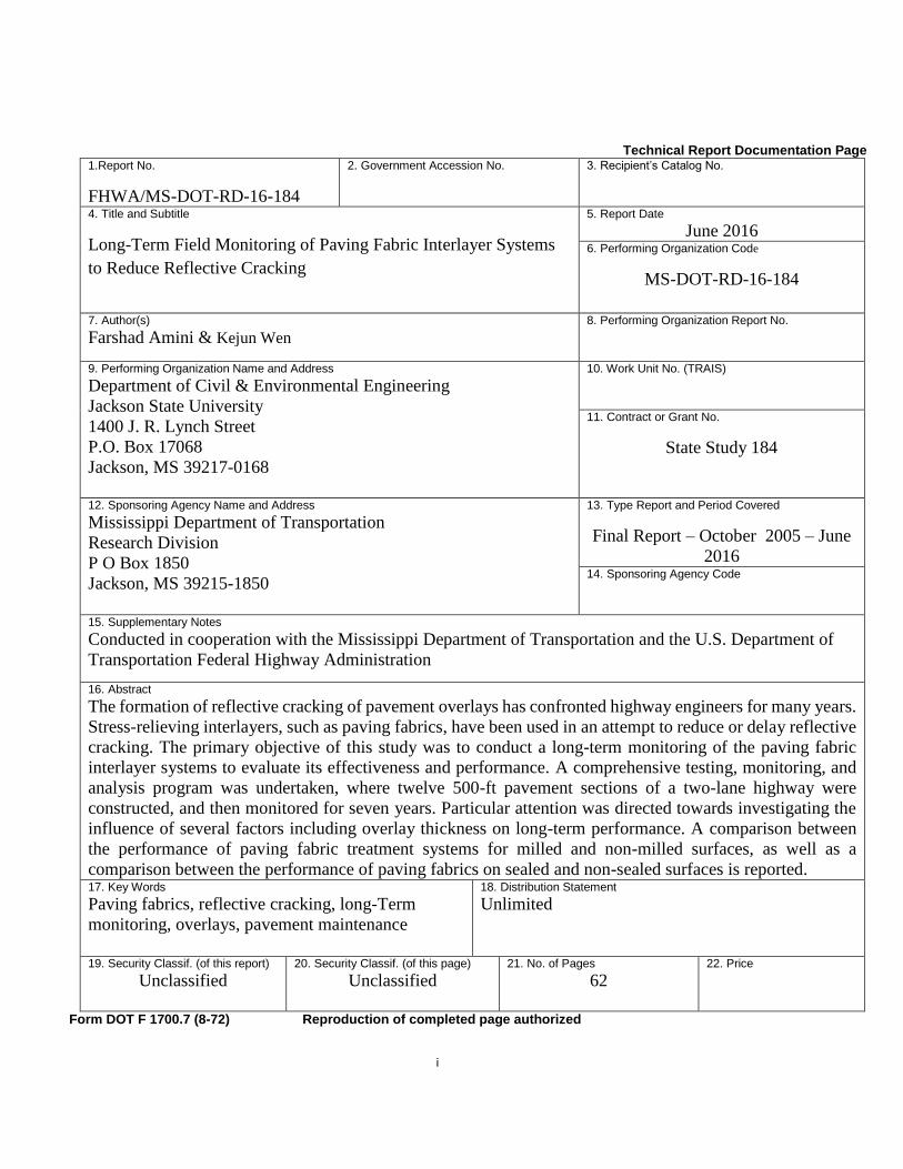
16. Abstract
The formation of reflective cracking of pavement overlays has confronted highway engineers for many years.
Stress-relieving interlayers, such as paving fabrics, have been used in an attempt to reduce or delay reflective
cracking. The primary objective of this study was to conduct a long-term monitoring of the paving fabric
interlayer systems to evaluate its effectiveness and performance. A comprehensive testing, monitoring, and
analysis program was undertaken, where twelve 500-ft pavement sections of a two-lane highway were
constructed, and then monitored for seven years. Particular attention was directed towards investigating the
influence of several factors including overlay thickness on long-term performance. A comparison between
the performance of paving fabric treatment systems for milled and non-milled surfaces, as well as a
comparison between the performance of paving fabrics on sealed and non-sealed surfaces is reported. 17. Key Words
Paving fabrics, reflective cracking, long-Term
monitoring, overlays, pavement maintenance
18. Distribution Statement
Unlimited
19. Security Classif. (of this report)
Unclassified 20. Security Classif. (of this page)
Unclassified
21. No. of Pages
62 22. Price
Form DOT F 1700.7 (8-72) Reproduction of completed page authorized

ii
ACKNOWLEDGEMENT
This report presents the results of a study titled “Long-Term Monitoring and
Performance of Paving Fabrics Interlayer Systems to Reduce Reflective Cracking”, conducted
by the Department of Civil and Environmental Engineering, Jackson State University, in
cooperation with the Mississippi Department of Transportation (MDOT) and the U.S.
Department of Transportation, Federal Highway Administration.
The author would like to express his sincere appreciation to Mr. William Barstis of the
MDOT’s Research Division, for his contribution and constant encouragement. Dr. Randy
Ahlrich, of the Burns, Cooley, and Dennis, Inc. (BCD) contributed heavily to this research
during the various phases of the project and during the preparation of the final report. Ms.
Cindy Smith of the MDOT’s Research Division coordinated several research tasks, and
participated in many of the research meetings. Thanks are also extended to the MDOT districts
engineers particularly Mr. Alan Cross for identifying a construction project and for sharing his
experience with paving fabrics. Thanks are also due to the MDOT Research Advisory
Committee for their interest in this project.
DISCLAIMER
The contents of this report reflect the views of the author who is responsible for the
facts and accuracy of the information provided. The contents do not necessarily reflect the
views or policies of the Mississippi Department of Transportation at the time of publication.
This report does not constitute a standard, specification, or regulation.
iii
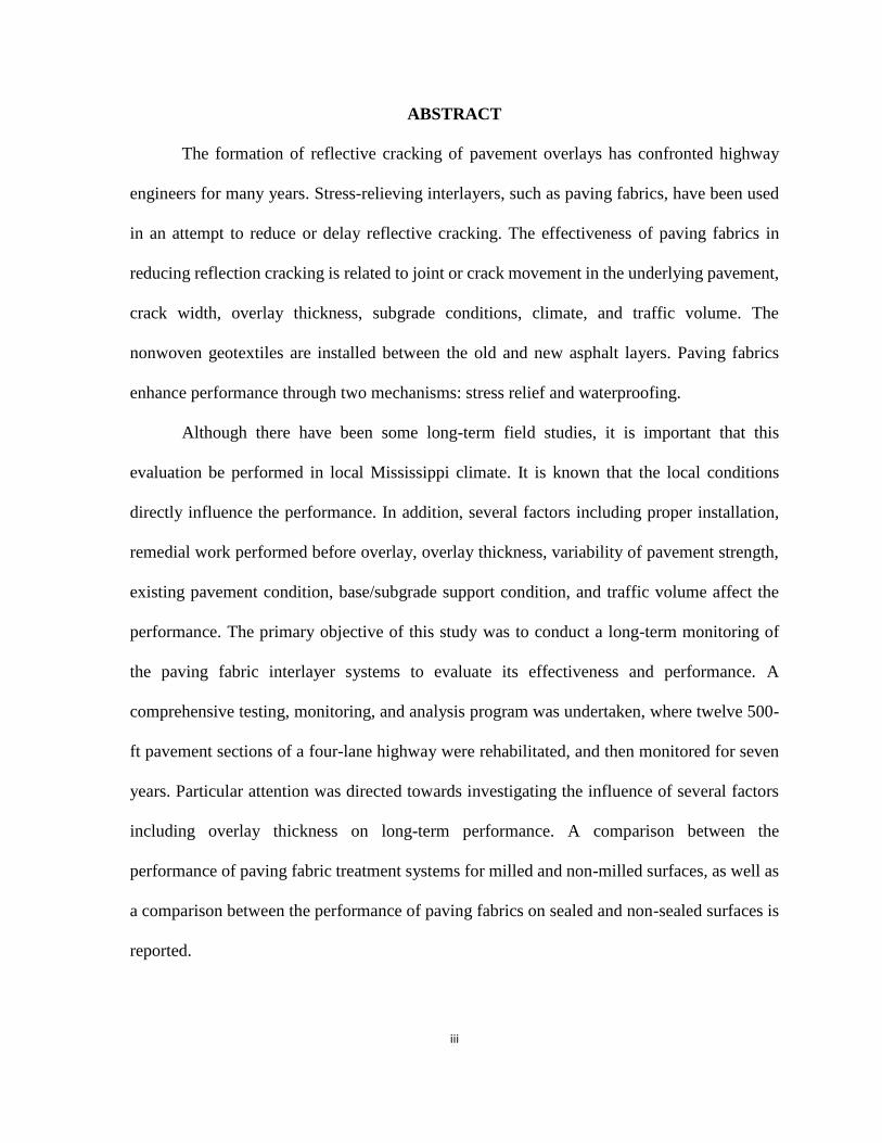
ABSTRACT
The formation of reflective cracking of pavement overlays has confronted highway
engineers for many years. Stress-relieving interlayers, such as paving fabrics, have been used
in an attempt to reduce or delay reflective cracking. The effectiveness of paving fabrics in
reducing reflection cracking is related to joint or crack movement in the underlying pavement,
crack width, overlay thickness, subgrade conditions, climate, and traffic volume. The
nonwoven geotextiles are installed between the old and new asphalt layers. Paving fabrics
enhance performance through two mechanisms: stress relief and waterproofing.
Although there have been some long-term field studies, it is important that this
evaluation be performed in local Mississippi climate. It is known that the local conditions
directly influence the performance. In addition, several factors including proper installation,
remedial work performed before overlay, overlay thickness, variability of pavement strength,
existing pavement condition, base/subgrade support condition, and traffic volume affect the
performance. The primary objective of this study was to conduct a long-term monitoring of
the paving fabric interlayer systems to evaluate its effectiveness and performance. A
comprehensive testing, monitoring, and analysis program was undertaken, where twelve 500-
ft pavement sections of a four-lane highway were rehabilitated, and then monitored for seven
years. Particular attention was directed towards investigating the influence of several factors
including overlay thickness on long-term performance. A comparison between the
performance of paving fabric treatment systems for milled and non-milled surfaces, as well as
a comparison between the performance of paving fabrics on sealed and non-sealed surfaces is
reported.
iv
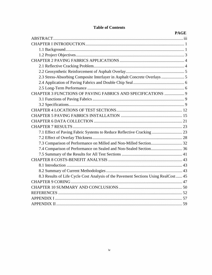
Table of Contents
PAGE
ABSTRACT ............................................................................................................................. iii
CHAPTER I INTRODUCTION ............................................................................................... 1
1.1 Background .................................................................................................................. 1
1.2 Project Objectives ........................................................................................................ 3
CHAPTER 2 PAVING FABRICS APPLICATIONS .............................................................. 4
2.1 Reflective Cracking Problem....................................................................................... 4
2.2 Geosynthetic Reinforcement of Asphalt Overlay ........................................................ 5
2.3 Stress-Absorbing Composite Interlayer in Asphalt Concrete Overlays ...................... 5
2.4 Application of Paving Fabrics and Double Chip Seal ................................................. 6
2.5 Long-Term Performance ............................................................................................. 6
CHAPTER 3 FUNCTIONS OF PAVING FABRICS AND SPECIFICATIONS ................... 9
3.1 Functions of Paving Fabrics ........................................................................................ 9
3.2 Specifications............................................................................................................... 9
CHAPTER 4 LOCATIONS OF TEST SECTIONS ............................................................... 12
CHAPTER 5 PAVING FABRICS INSTALLATION ........................................................... 15
CHAPTER 6 DATA COLLECTION ..................................................................................... 21
CHAPTER 7 RESULTS ......................................................................................................... 23
7.1 Effect of Paving Fabric Systems to Reduce Reflective Cracking ............................. 23
7.2 Effect of Overlay Thickness ...................................................................................... 28
7.3 Comparison of Performance on Milled and Non-Milled Section .............................. 32
7.4 Comparison of Performance on Sealed and Non-Sealed Section .............................. 36
7.5 Summary of the Results for All Test Sections .......................................................... 41
CHAPTER 8 COSTS-BENEFIT ANALYSIS ....................................................................... 43
8.1 Introduction ............................................................................................................... 43
8.2 Summary of Current Methodologies ......................................................................... 43
8.3 Results of Life Cycle Cost Analysis of the Pavement Sections Using RealCost ...... 45
CHAPTER 9 CORING ........................................................................................................... 47
CHAPTER 10 SUMMARY AND CONCLUSIONS ............................................................. 50
REFERENCES ....................................................................................................................... 52
APPENDIX I .......................................................................................................................... 57
APPENDIX II ......................................................................................................................... 59

v
LIST OF FIGURES
FIGURE PAGE
Figure 4.1 Typical Transverse Crack in Pavement 12
Figure 4.2 Typical Longitudinal Crack in Pavement 13
Figure 5.1 Applying Uniform Tack Coat on Test Section 16
Figure 5.2 Placing Fabric on Test Section 19
Figure 5.3 Placement of Paving Fabric 19
Figure 5.4 Wrinkles after Placement of Fabric 20
Figure 5.5 Engineer Inspecting of Fabric after Placement 20
Figure 7.1.1 Performance of Pavement with and without Paving Fabrics, (a)
1.5 in (38.1 mm) Overlay Thickness; (b) 3.0 in (76.2 mm)
Overlay Thickness 24
Figure 7.1.2 Equivalency between Performance of Pavement with Paving
Fabrics and Thicker Overlay Control Section 25
Figure 7.1.3 Milled Test Section 26
Figure 7.1.4 Sealing Cracks in Section 7 26
Figure 7.1.5 Performance of Pavement with and without Paving Fabrics
under Milling and Sealing Conditions 28
Figure 7.2.1 Performance of Pavement without Paving Fabrics for Various
Overlay Thicknesses 29
Figure 7.2.2 Performance of Pavement with Paving Fabrics for Various
Overlay Thicknesses 30
Figure 7.2.3 Performance of Pavement with Paving Fabrics and Milling
Method for Various Overlay Thicknesses 31
Figure 7.2.4 Performance of Pavement with Paving Fabrics and Sealing
Method for Various Overlay Thicknesses 32
Figure 7.3.1 Performance of Pavement without Paving Fabrics under Milling
Method 33
Figure 7.3.2 Performance of Pavement with Paving Fabrics under Milling
Method, (a) 1.5 in Overlay Thickness (38.1 mm); (b) 3.0 in
(76.2 mm) Overlay Thickness 34
Figure 7.3.3 Effect of Milling on Different Cracking Type 35
Figure 7.3.4 Equivalency between Paving Fabrics with Milling and Thicker
Overlay Control Section 36
Figure 7.4.1 Performance of Pavement without Paving Fabrics under Sealing
Method 37
Figure 7.4.2 Performance of Pavement with Paving Fabrics under Sealing
Method, (a) 1.5 in. Overlay Thickness (38.1 mm); (b) 3.0 in
(76.2 mm) Overlay Thickness 38
Figure 7.4.3 Cracks Over-Sealed in Sealed Section 39
Figure 7.4.4 Damage of Over Sealed Cracks 39
Figure 7.4.5 Equivalency between Paving Fabrics with Sealing and Thicker
Overlay Control Section 40
vi
Figure 7.5.1 Summary of All Test Sections 41
Figure 8.1 Cost Analysis of Five Different Type Test Sections 44
Figure 9.1 Effect of Paving Fabrics on Moisture Damage 46
Figure 9.2 Coring Sample at Section 6 in 2007 47
Figure 9.3 Coring Sample at Section 6 in 2011 47
Figure 9.4 Coring Sample at Section 6 in 2014 47

vii
LIST OF TABLES
TABLE PAGE
Table 4.1 Summary of Research Sections 22
Table 6.1 Cracking Data 33
Table 7.1 Ranking of All Test Sections 42
Table 8.1 Life Cycle Cost Analysis Results 52

1
CHAPTER I
INTRODUCTION
1.1 Background
Pavement rehabilitation programs are consuming an increasing percentage of the
available transportation system construction funds at many highway departments. The overall
objective of any rehabilitation scheme is to return the pavement to a safe condition, and to
provide a high level of serviceability. Any rehabilitation method must be carefully engineered
to ensure the rehabilitated pavement has sufficient structural strength to perform satisfactorily.
One of the most commonly used techniques for rehabilitating deteriorated pavements has been
the application of asphalt concrete overlay. A major type of distress influencing the life of an
overlay is reflective cracking (e.g., Dempsey, 2002). When an overlay is placed on existing
pavement, physical tearing of the overlay occurs because of movements at the joints and cracks
in the underlying pavement layer. This phenomenon is commonly defined as the propagation
of cracks due to the movement of the underlying pavement or base course into and through the
new overlay as a result of load-induced and/or temperature-induced stresses (Cleveland et al.,
2002). Load induced vertical movement leads to shear stresses in the overlay, and is an
important contributing factor to reflective cracking. Temperature-associated horizontal
movement leads to tensile stresses, and also contributes to reflective cracking. Reflective
cracking in the overlay allows water to penetrate into the pavement structure and weaken the
subbase, and which contributes to many forms of pavement deterioration.
Considerable efforts have been expended over the years to develop treatment
techniques to reduce or delay reflective cracking. These techniques may be grouped into four
2
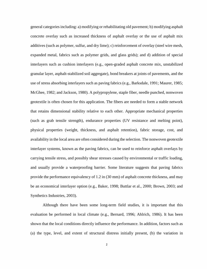
general categories including: a) modifying or rehabilitating old pavement; b) modifying asphalt
concrete overlay such as increased thickness of asphalt overlay or the use of asphalt mix
additives (such as polymer, sulfur, and dry lime); c) reinforcement of overlay (steel wire mesh,
expanded metal, fabrics such as polymer grids, and glass grids); and d) addition of special
interlayers such as cushion interlayers (e.g., open-graded asphalt concrete mix, unstabilized
granular layer, asphalt-stabilized soil aggregate), bond breakers at joints of pavements, and the
use of stress absorbing interlayers such as paving fabrics (e.g., Barksdale, 1991; Maurer, 1985;
McGhee, 1982; and Jackson, 1980). A polypropylene, staple fiber, needle punched, nonwoven
geotextile is often chosen for this application. The fibers are needed to form a stable network
that retains dimensional stability relative to each other. Appropriate mechanical properties
(such as grab tensile strength), endurance properties (UV resistance and melting point),
physical properties (weight, thickness, and asphalt retention), fabric storage, cost, and
availability in the local area are often considered during the selection. The nonwoven geotextile
interlayer systems, known as the paving fabrics, can be used to reinforce asphalt overlays by
carrying tensile stress, and possibly shear stresses caused by environmental or traffic loading,
and usually provide a waterproofing barrier. Some literature suggests that paving fabrics
provide the performance equivalency of 1.2 in (30 mm) of asphalt concrete thickness, and may
be an economical interlayer option (e.g., Baker, 1998; Buttlar et al., 2000; Brown, 2003; and
Synthetics Industries, 2003).
Although there have been some long-term field studies, it is important that this
evaluation be performed in local climate (e.g., Bernard, 1996; Ahlrich, 1986). It has been
shown that the local conditions directly influence the performance. In addition, factors such as
(a) the type, level, and extent of structural distress initially present, (b) the variation in
3
structural strength among test sections within a study, (c) the specific level of remedial work
performed on the pavement before the placement of overlay, and (d) overlay thickness may
influence the performance (e.g., Barksdale, 1991).
1.2 Project Objectives
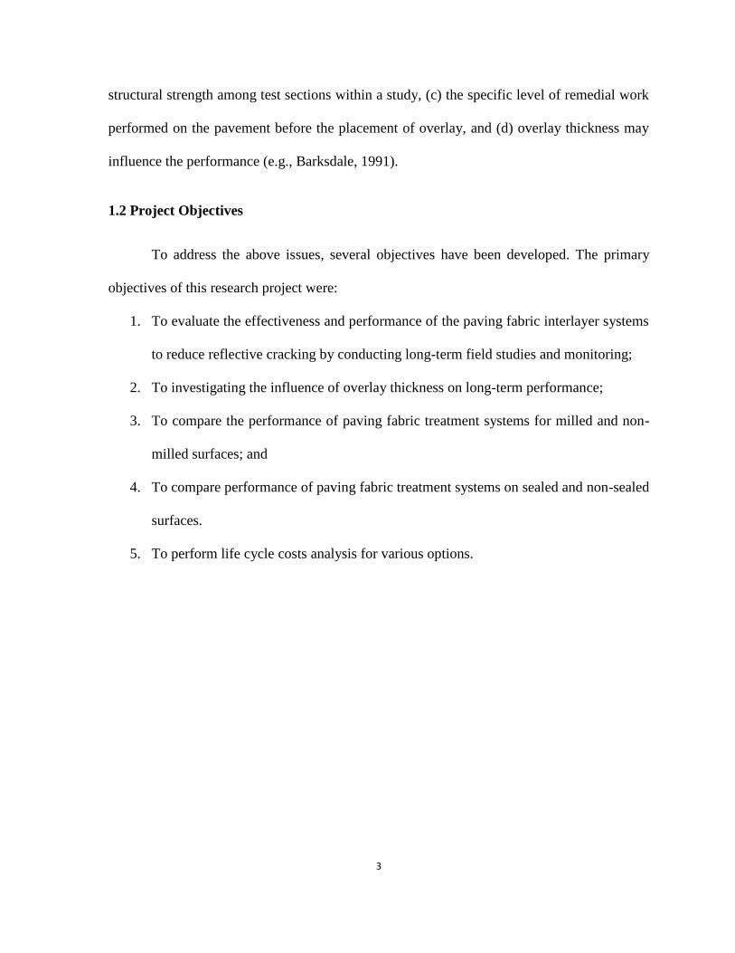
To address the above issues, several objectives have been developed. The primary
objectives of this research project were:
1. To evaluate the effectiveness and performance of the paving fabric interlayer systems
to reduce reflective cracking by conducting long-term field studies and monitoring;
2. To investigating the influence of overlay thickness on long-term performance;
3. To compare the performance of paving fabric treatment systems for milled and non-
milled surfaces; and
4. To compare performance of paving fabric treatment systems on sealed and non-sealed
surfaces.
5. To perform life cycle costs analysis for various options.
4
CHAPTER 2
PAVING FABRICS APPLICATIONS
In this section, the reflective cracking problem is first defined. Then, several techniques
of using geosynthetics for the purpose of controlling reflective cracking are discussed. Finally,
a brief summary of available literature on the long-term performance of paving fabric systems
is presented. A comprehensive study of the state-of-the-art applications of paving fabrics is
included in Amini (2005).
2.1 Reflective Cracking Problem
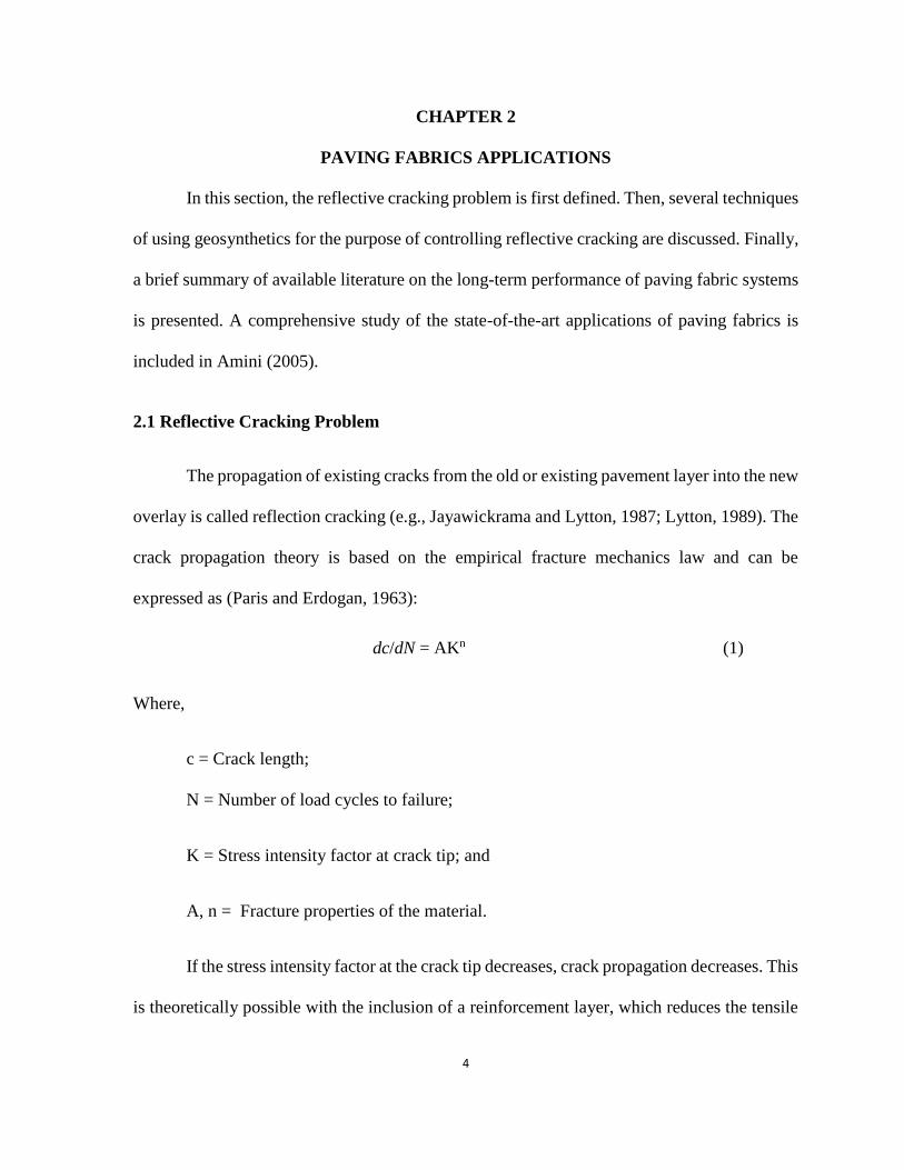
The propagation of existing cracks from the old or existing pavement layer into the new
overlay is called reflection cracking (e.g., Jayawickrama and Lytton, 1987; Lytton, 1989). The
crack propagation theory is based on the empirical fracture mechanics law and can be
expressed as (Paris and Erdogan, 1963):
dc/dN = AKn (1)
Where,
c = Crack length;
N = Number of load cycles to failure;
K = Stress intensity factor at crack tip; and
A, n = Fracture properties of the material.
If the stress intensity factor at the crack tip decreases, crack propagation decreases. This
is theoretically possible with the inclusion of a reinforcement layer, which reduces the tensile

5
stress at the crack tip (e.g., Barksdale, 1991; Paris and Erdogan, 1963; Kutuk, 1998). Several
treatment techniques have been introduced to reduce or prevent reflective cracking. These are
discussed below.
2.2 Geosynthetic Reinforcement of Asphalt Overlay
Sprague et al. (1998) described the mechanisms that lead to the enhanced performance
of reinforced overlays. They showed that the high-stiffness grids and fabrics can possibly turn
a reflective crack into a horizontal plane beneath the interlayer and delay reflective cracking
indefinitely, provided they are constructed properly. However, specifying the appropriate
reinforcing material relies on the uniform definition and measurement of stiffness of the
interlayer, so that materials can be properly compared.
2.3 Stress-Absorbing Composite Interlayer in Asphalt Concrete Overlays
Dempsey (2002) described an interlayer stress-absorbing composite (ISAC) for the
purpose of alleviating or mitigating the problem of reflection cracking in an asphalt concrete
(AC) overlay. The ISAC system consists of a low-modulus, low-stiffness geotextile as the
bottom layer, a viscoelastic membrane layer (such as a blend of vulcanized rubber and
appropriate viscosity asphalt) as the core, and a very high stiffness geotextile [(with stiffness
greater than 48 kips/ft or (700 KN/m)] for the upper layer. A tack coat is needed on the existing
pavement surface prior to placement of the ISAC material. A tack coat may also be required
between the ISAC layer and the AC overlay. Several years of field performance testing have
shown that the ISAC system is highly effective for mitigating reflective cracking in AC
overlays used on both airport and highway pavement systems.
6
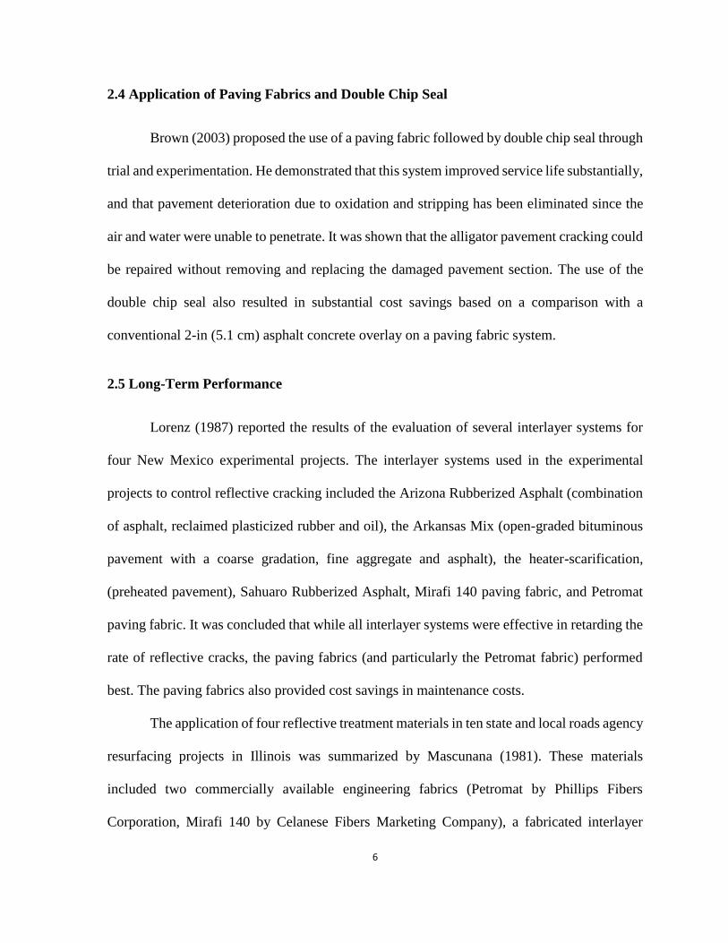
2.4 Application of Paving Fabrics and Double Chip Seal
Brown (2003) proposed the use of a paving fabric followed by double chip seal through
trial and experimentation. He demonstrated that this system improved service life substantially,
and that pavement deterioration due to oxidation and stripping has been eliminated since the
air and water were unable to penetrate. It was shown that the alligator pavement cracking could
be repaired without removing and replacing the damaged pavement section. The use of the
double chip seal also resulted in substantial cost savings based on a comparison with a
conventional 2-in (5.1 cm) asphalt concrete overlay on a paving fabric system.
2.5 Long-Term Performance
Lorenz (1987) reported the results of the evaluation of several interlayer systems for
four New Mexico experimental projects. The interlayer systems used in the experimental
projects to control reflective cracking included the Arizona Rubberized Asphalt (combination
of asphalt, reclaimed plasticized rubber and oil), the Arkansas Mix (open-graded bituminous
pavement with a coarse gradation, fine aggregate and asphalt), the heater-scarification,
(preheated pavement), Sahuaro Rubberized Asphalt, Mirafi 140 paving fabric, and Petromat
paving fabric. It was concluded that while all interlayer systems were effective in retarding the
rate of reflective cracks, the paving fabrics (and particularly the Petromat fabric) performed
best. The paving fabrics also provided cost savings in maintenance costs.
The application of four reflective treatment materials in ten state and local roads agency
resurfacing projects in Illinois was summarized by Mascunana (1981). These materials
included two commercially available engineering fabrics (Petromat by Phillips Fibers
Corporation, Mirafi 140 by Celanese Fibers Marketing Company), a fabricated interlayer
7
membrane (Heavy Duty Bituthene by W. R. Grace & Company), and an asphalt-rubber
membrane interlayer. The findings of this study indicated that the treatment methods were not
effective in preventing the development of transverse reflective cracking on overlays with rigid
bases. However, they controlled longitudinal reflective cracking. In addition, they were
generally effective in reducing or retarding both transverse and longitudinal reflective cracking
on overlays with flexible bases.
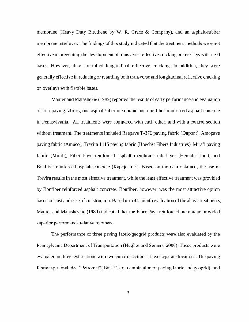
Maurer and Malashekie (1989) reported the results of early performance and evaluation
of four paving fabrics, one asphalt/fiber membrane and one fiber-reinforced asphalt concrete
in Pennsylvania. All treatments were compared with each other, and with a control section
without treatment. The treatments included Reepave T-376 paving fabric (Dupont), Amopave
paving fabric (Amoco), Trevira 1115 paving fabric (Hoechst Fibers Industries), Mirafi paving
fabric (Mirafi), Fiber Pave reinforced asphalt membrane interlayer (Hercules Inc.), and
Bonfiber reinforced asphalt concrete (Kapejo Inc.). Based on the data obtained, the use of
Trevira results in the most effective treatment, while the least effective treatment was provided
by Bonfiber reinforced asphalt concrete. Bonfiber, however, was the most attractive option
based on cost and ease of construction. Based on a 44-month evaluation of the above treatments,
Maurer and Malasheskie (1989) indicated that the Fiber Pave reinforced membrane provided
superior performance relative to others.
The performance of three paving fabric/geogrid products were also evaluated by the
Pennsylvania Department of Transportation (Hughes and Somers, 2000). These products were
evaluated in three test sections with two control sections at two separate locations. The paving
fabric types included “Petromat”, Bit-U-Tex (combination of paving fabric and geogrid), and

8
“Glassgrid”. Based on the results of this study, none of the three paving fabric/geogrid types
were found to be effective in preventing or retarding reflective cracking.
In summary, the long-term monitoring has generally indicated that paving fabrics can
be very effective in reducing reflective cracking. However, paving fabrics may not reduce
cracking significantly with thin overlays.
9
CHAPTER 3
FUNCTIONS OF PAVING FABRICS AND SPECIFICATIONS
3.1 Functions of Paving Fabrics
The paving fabric interlayer systems are recognized to extend the service life of
overlays. The major functions of geosynthetic materials for pavement interlayer applications
are reinforcement and water proofing. In providing reinforcement, the geosynthetic material
structurally strengthens the pavement section by changing the response of the pavement to
loading (Koerner, 2005). In the waterproofing function, the paving fabric can help maintain
lower moisture content beneath the pavement by minimizing water infiltration through the
pavement (e.g., Burmania, 1988; Marienfeld and Baker, 1999; Brown, 2000). Maintaining the
materials at a lower level of moisture can result in maintaining the strength of materials at
higher levels. The relative contribution of the two functions depends on the pavement condition
and the environment (e.g., Buttlar, et al., 1999).
3.2 Specifications
The designer often provides specifications for the fabric properties. These properties
can be tested using ASTM or AASHTO standards (e.g., Roads and Bridges, 1989). The most
commonly used paving fabric properties include the following (e.g., Barazone, 2000): weight:
oz/sq yd; grab tensile strength (weakest principle direction); elongation; asphalt retention;
fabric storage; and melting point.

10
Weight/sq yd refers to the quantity of fabric needed to absorb a sufficient
amount of tack coat to form a membrane. Most specifications require four-oz/sq
yd.
Grab tensile strength is an important property indicating the fabric’s strength
when it is pulled between the jaws of a testing machine until it ruptures. A grab
tensile strength in the range of 115 lbs (512 N) or greater is usually specified.
Elongation is also determined from the grab tensile test. It measures the percent
the fabric stretched at maximum strength. Most agencies require an elongation
of between 50 and 100%.
Asphalt retention is an important property for this application, and is an
indication of how much asphalt is necessary to saturate the fabric and make a
bond. Various fabrics absorb different amounts of tack coat depending upon
weight and thickness. A typical 4-oz/sq yd (136 gm/sq m) fabric will absorb
about 0.20 gal/yd2 (0.91 liters/m2). An additional 0.05 gal/yd2 (0.023 liters/m2)
of tack coat should be included for bonding to the old and new asphalt concrete
layers.
Improper storage can cause many problems. Damage to plastic wrappers allows
moisture and UV rays to reach the fabric, breaking down some fibers in a very
short time.
Melting point in the range of 300 degrees F (150 degrees C) or greater are often
required.
Among the above properties, grab tensile strength and asphalt retention are the most
critical ones. AASHTO M288 (AASHTO, 1993) also lists current commercial paving fabrics
11
that satisfy AASHTO default specifications for the application (e.g., Suits and Richardson,
1998; Suits, 1999; Suits, 2001). Manufacturers typically provide at least the following
information: mechanical properties (grab tensile strength, grab elongation, puncture strength,
Mullen burst, and trapezoidal tear), endurance properties (UV resistance and melting point),
physical properties (weight, thickness, and asphalt retention), fabric storage, and roll size.
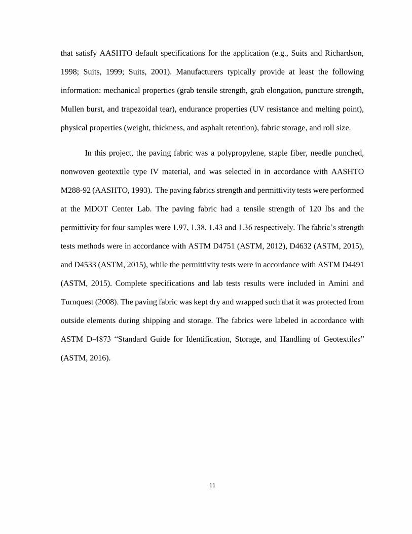
In this project, the paving fabric was a polypropylene, staple fiber, needle punched,
nonwoven geotextile type IV material, and was selected in in accordance with AASHTO
M288-92 (AASHTO, 1993). The paving fabrics strength and permittivity tests were performed
at the MDOT Center Lab. The paving fabric had a tensile strength of 120 lbs and the
permittivity for four samples were 1.97, 1.38, 1.43 and 1.36 respectively. The fabric’s strength
tests methods were in accordance with ASTM D4751 (ASTM, 2012), D4632 (ASTM, 2015),
and D4533 (ASTM, 2015), while the permittivity tests were in accordance with ASTM D4491
(ASTM, 2015). Complete specifications and lab tests results were included in Amini and
Turnquest (2008). The paving fabric was kept dry and wrapped such that it was protected from
outside elements during shipping and storage. The fabrics were labeled in accordance with
ASTM D-4873 “Standard Guide for Identification, Storage, and Handling of Geotextiles”
(ASTM, 2016).

12
CHAPTER 4
LOCATIONS OF TEST SECTIONS
The project site is located in the City of Pearl, Rankin County, MS in the outside
lane of US 80 in the westbound direction, beginning at the west side of the US 80/SR 475
intersection and extending approximately 1 ¼ miles (2 km) to a point approximately ¼ mile
(402 m) west of South Fox Hall Road. A map for the site location is shown in Appendix I.
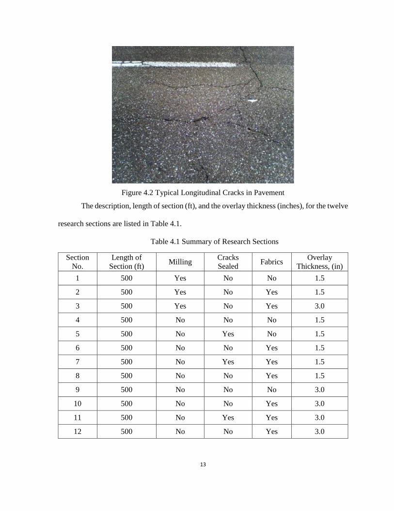
Figures 4.1 and 4.2 show typical transverse and longitudinal cracks in the existing
pavement. This portion of roadway indicates many distresses in asphalt pavements including
raveling and transverse cracking with the need for milling, sealing, and overlay. There were
cracks of considerable lengths and widths, small pot holes, and sections with uneven roadway.
These characteristics made this part of roadway a suitable location for research purposes.
Figure 4.1 Typical Longitudinal Cracks in Pavement
13
Figure 4.2 Typical Longitudinal Cracks in Pavement
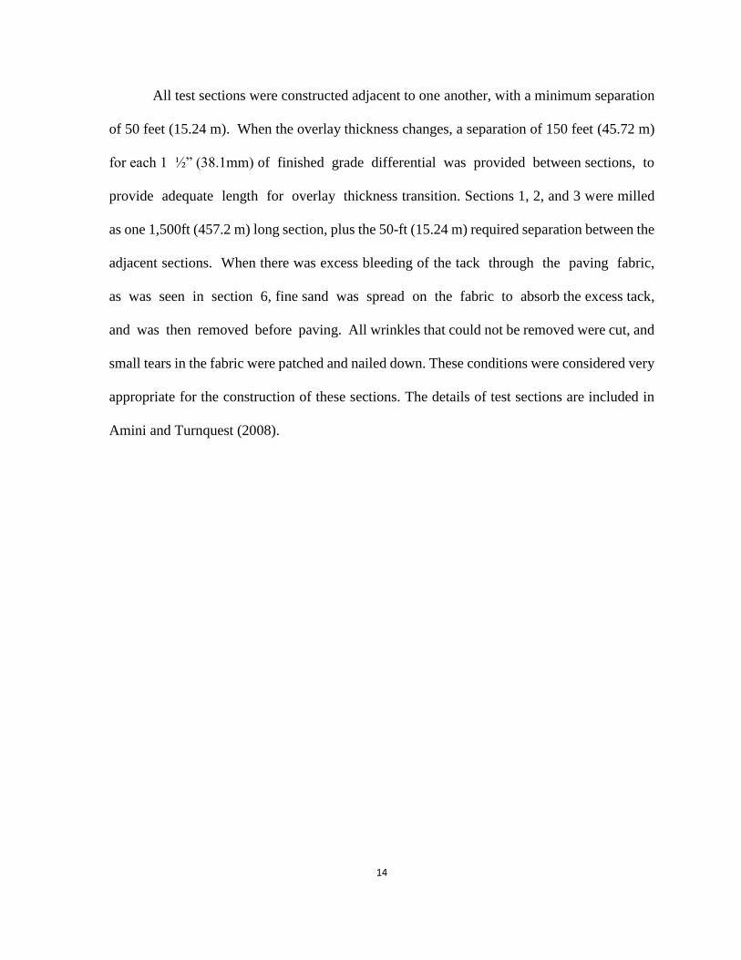
The description, length of section (ft), and the overlay thickness (inches), for the twelve
research sections are listed in Table 4.1.
Table 4.1 Summary of Research Sections
Section
No.
Length of
Section (ft) Milling
Cracks
Sealed Fabrics
Overlay
Thickness, (in)
1 500 Yes No No 1.5
2 500 Yes No Yes 1.5
3 500 Yes No Yes 3.0
4 500 No No No 1.5
5 500 No Yes No 1.5
6 500 No No Yes 1.5
7 500 No Yes Yes 1.5
8 500 No No Yes 1.5
9 500 No No No 3.0
10 500 No No Yes 3.0
11 500 No Yes Yes 3.0
12 500 No No Yes 3.0
14
All test sections were constructed adjacent to one another, with a minimum separation
of 50 feet (15.24 m). When the overlay thickness changes, a separation of 150 feet (45.72 m)
for each 1 ½” (38.1mm) of finished grade differential was provided between sections, to
provide adequate length for overlay thickness transition. Sections 1, 2, and 3 were milled
as one 1,500ft (457.2 m) long section, plus the 50-ft (15.24 m) required separation between the
adjacent sections. When there was excess bleeding of the tack through the paving fabric,
as was seen in section 6, fine sand was spread on the fabric to absorb the excess tack,
and was then removed before paving. All wrinkles that could not be removed were cut, and
small tears in the fabric were patched and nailed down. These conditions were considered very
appropriate for the construction of these sections. The details of test sections are included in
Amini and Turnquest (2008).

15
CHAPTER 5
PAVING FABRICS INSTALLATION
Several studies have reported the significance of proper installation in achieving the
desired function for the paving fabric systems (e.g., Rahman, et al., 1989; Baker, 1998; and
Barazone, 2000). The fact that paving fabrics have been found to be an effective treatment
system in test sections is largely due to tightly controlled installation procedures rigidly
adhered to for asphalt temperature, spread rate, fabric placement, wrinkles and overlaps. To
assure the performance record for paving fabric, the installation specifications and guidelines
should be strictly enforced.
The installation of paving fabric system usually follows the same general pattern
wherever it is used. First, the surface is prepared by removing loose material and sealing cracks,
as necessary. Sealing the cracks is particularly important if there is a lot of random cracking,
¼- to 3/8- in. (6.3 to 9.5 mm) wide. The cracks should be filled with suitable crack filler
material. The primary purpose of crack sealing is to fill voids to prevent the fabric from
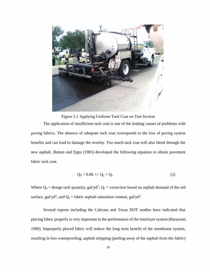
spanning a crack. A tack coat (such as asphalt-cement) is then applied to the existing pavement
surface (see Figure 5.1). Typically, a tack-coat application of approximately 0.25 gal/yd2 (1.1
liters/m2) is recommended. After spraying on the tack coat, the paving fabric is rolled onto the
sprayed surface. Finally an asphalt-cement concrete overlay is placed over the fabric. The heat
of the overlay and the pressure applied by its compaction force the tack coat into the paving
fabric and complete the process (Baker, 1998).
16
Figure 5.1 Applying Uniform Tack Coat on Test Section
The application of insufficient tack coat is one of the leading causes of problems with
paving fabrics. The absence of adequate tack coat corresponds to the loss of paving system
benefits and can lead to damage the overlay. Too much tack coat will also bleed through the
new asphalt. Button and Epps (1983) developed the following equation to obtain pavement
fabric tack coat.
Qd = 0.08 +/- Qc + Qs (2)
Where Qd = design tack quantity; gal/yd2; Qc = correction based on asphalt demand of the old
surface, gal/yd2; and Qs = fabric asphalt saturation content, gal/yd2.
Several reports including the Caltrans and Texas DOT studies have indicated that
placing fabric properly is very important in the performance of the interlayer system (Barazone,
1990). Improperly placed fabric will reduce the long term benefit of the membrane system,
resulting in less waterproofing, asphalt stripping (peeling away of the asphalt from the fabric)
17
and cracks from heat damage, wrinkles, overlaps and in wheel paths. Mechanized fabric
placement is faster than hand placement. When placing fabrics, the shiny, heat-bonded side
should be up, exposed to traffic. If paving fabrics is placed in extreme temperatures (90 to 95
degrees F), some sand should be placed on fabric to keep traffic from picking up the material.
Many published reports indicate that wrinkles and overlaps in the fabric can cause cracks in
the new overlay if not properly handled during construction process. Winkles twice the
thickness of the fabric should be slit at the bottom of the wrinkle and laid flat. Overlaps and
slit wrinkles should be laid at top of each other. A 2- to 3-in. (2.54 to 7.62-cm) overlap on the
fabric is often recommended (Roads and Bridges, 1989). It should also be noted that
installation around curves without producing excessive wrinkles requires proper procedures
(Barazone, 2000).
Another problem during installation is the heat shrinkage. The most significant
shrinkage problem often occurs when the fabric is placed onto hot asphalt which exceeds the
fabric shrinkage temperature (Barazone, 1990). Los Angeles County, Texas, and Caltrans have
documented shrinkage of polypropylene fabrics when placed on hot asphalt material over 250
degrees F.
Barazone (1990) has indicated the minimum asphalt wearing course (overlay thickness)
of 1 ½ to 2 inches (3.81 to 5.08 cm) in ideal paving temperatures (above 70 degrees F), and
minimum of 2 inches (5.08 cm) in less than ideal temperatures (between 50 and 70 degrees F).
Overlays should not be attempted with temperatures less than 50 degrees F. The heat from the
overlay draws the asphalt material up through the fabric making a bond. It may also be noted
that paving fabrics are recyclable in both hot and cold milling processes.
18
Rahman, et al. (1989) documented the results of the installation of three commercial
paving fabrics for the reduction of reflective cracking in asphalt overlays in Arizona. The
fabrics installed were Paveprep (PavePrep Corporation), Glassgrid (Bay Mills Ltd.) and
Tapecoat (Tapecoat Company). Their recommendations included 1) the need for proper binder
coat selection based on the expected construction conditions and product selections when
paving fabrics are used in pavement rehabilitation; 2) the need for additional field testing of
Paveprep on milled surfaces; and 3) caution regarding the use of Glassgrid on rough surfaces.
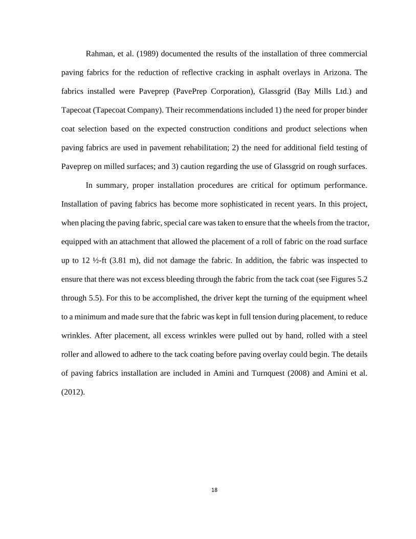
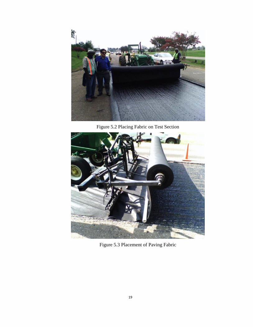
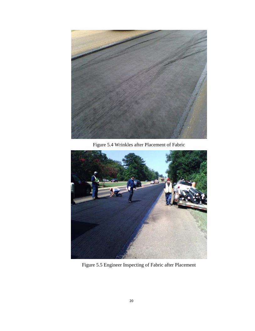
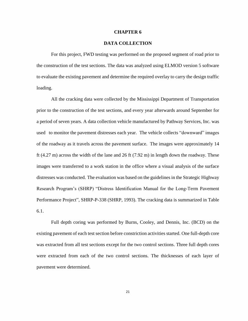
In summary, proper installation procedures are critical for optimum performance.
Installation of paving fabrics has become more sophisticated in recent years. In this project,
when placing the paving fabric, special care was taken to ensure that the wheels from the tractor,
equipped with an attachment that allowed the placement of a roll of fabric on the road surface
up to 12 ½-ft (3.81 m), did not damage the fabric. In addition, the fabric was inspected to
ensure that there was not excess bleeding through the fabric from the tack coat (see Figures 5.2
through 5.5). For this to be accomplished, the driver kept the turning of the equipment wheel
to a minimum and made sure that the fabric was kept in full tension during placement, to reduce
wrinkles. After placement, all excess wrinkles were pulled out by hand, rolled with a steel
roller and allowed to adhere to the tack coating before paving overlay could begin. The details
of paving fabrics installation are included in Amini and Turnquest (2008) and Amini et al.
(2012).
19
Figure 5.2 Placing Fabric on Test Section
Figure 5.3 Placement of Paving Fabric
20
Figure 5.4 Wrinkles after Placement of Fabric
Figure 5.5 Engineer Inspecting of Fabric after Placement
21
CHAPTER 6
DATA COLLECTION
For this project, FWD testing was performed on the proposed segment of road prior to
the construction of the test sections. The data was analyzed using ELMOD version 5 software
to evaluate the existing pavement and determine the required overlay to carry the design traffic
loading.
All the cracking data were collected by the Mississippi Department of Transportation
prior to the construction of the test sections, and every year afterwards around September for
a period of seven years. A data collection vehicle manufactured by Pathway Services, Inc. was
used to monitor the pavement distresses each year. The vehicle collects “downward” images
of the roadway as it travels across the pavement surface. The images were approximately 14
ft (4.27 m) across the width of the lane and 26 ft (7.92 m) in length down the roadway. These
images were transferred to a work station in the office where a visual analysis of the surface
distresses was conducted. The evaluation was based on the guidelines in the Strategic Highway
Research Program’s (SHRP) “Distress Identification Manual for the Long-Term Pavement
Performance Project”, SHRP-P-338 (SHRP, 1993). The cracking data is summarized in Table
6.1.
Full depth coring was performed by Burns, Cooley, and Dennis, Inc. (BCD) on the
existing pavement of each test section before constriction activities started. One full-depth core
was extracted from all test sections except for the two control sections. Three full depth cores
were extracted from each of the two control sections. The thicknesses of each layer of
pavement were determined.

22
Table 6.1 Cracking Data
Section
No. Description
Overlay
Thickness
(in)
2006
(Total
Length,
in) 2007 2008 2009 2010 2011 2012 2013 2014
1 Control Section, No Paving
Fabrics, Milled, Non-Sealed 1.5 1458.4 0.00% 0.00% 0.27% 3.47% 5.99% 11.66% 27.23% 48.13%
2 Paving fabrics, Milled, Non-
Sealed 1.5 1700.6 0.00% 0.00% 0.00% 0.00% 0.00% 0.00% 2.94% 3.79%
3 Paving Fabrics, Milled, Non-
Sealed 3.0 1718.7 0.00% 0.00% 0.00% 0.00% 0.00% 1.20% 2.39% 4.26%
4
Control Section, No Paving
Fabrics, Non-Milled, Non-
Sealed
1.5 1340.9 0.00% 0.00% 1.44% 3.75% 4.25% 7.09% 8.43% 10.82%
5 Control, No Paving Fabrics,
Non-Milled, Sealed 1.5 1982.6 0.00% 0.00% 0.99% 3.89% 6.34% 9.17% 12.20% 15.63%
6 Paving Fabrics, Non-milled,
Non-Sealed 1.5 1773.3 0.00% 0.00% 0.00% 0.00% 0.58% 1.67% 2.83% 5.72%
7 Paving Fabrics, Non-Milled,
Sealed 1.5 1611 0.00% 0.00% 0.00% 0.50% 1.16% 2.84% 5.47% 10.01%
8 Paving Fabrics, Non-Milled,
Non-Sealed 1.5 1066.4 0.00% 0.00% 0.00% 0.00% 0.00% 0.16% 1.28% 3.03%
9
Control Section, No paving
Fabrics, Non-Milled, Non-
Sealed
3.0 1554 0.00% 0.00% 0.00% 0.00% 0.00% 0.13% 0.79% 2.12%
10 Paving Fabrics, Non-Milled,
Non-Sealed 3.0 1557.2 0.00% 0.00% 0.00% 0.00% 0.00% 0.00% 0.21% 0.53%
11 Paving Fabrics, Non-Milled,
Sealed 3.0 1121.8 0.00% 0.00% 0.00% 0.00% 0.00% 0.97% 2.79% 4.97%
12 Paving Fabrics, Non-Milled,
Non-Sealed 3.0 1358.1 0.00% 0.00% 0.00% 0.00% 0.00% 0.00% 0.26% 1.23%

23
CHAPTER 7
RESULTS
In this section, the results of the long-term monitoring are provided. In particular, the
effects of paving fabric, overlay thickness, as well as milling and sealing on the long term
performance of the pavement sections are presented and discussed.
7.1 Effect of Paving Fabric Systems to Reduce Reflective Cracking
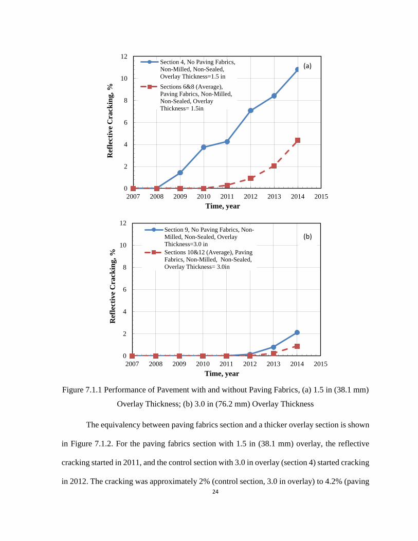
Figure 7.1.1 shows the effect of paving fabrics on the performance of the pavement
section. Figure 7.1.1 (a) compares the reflective cracking of the Section 4 and the average of
Sections 6 and 8 with 1.5 in. (38.1 mm) overlay thickness. As shown in this figure, Section 4
started cracking in 2008 and the reflective cracking increased to 11% by 2014. With the
addition of paving fabrics, the cracking started in 2010. By 2014, the reflective cracking in
Sections 6 and 8 increased to 4.3%, which was 40% of the cracking of Section 4. The pavement
without paving fabrics started to crack in 2009, while for Sections 6 and 8, it started to crack
in 2011. The improved performance of the paving fabrics section may be explained by the fact
that the paving fabrics provided higher shear strength to prevent or delay cracking. In addition,
the paving fabrics layer functioned as a waterproof barrier to prevent the water to go through
the sub base that could cause more structure damage. In Figure 7.1.1 (b), when the overlay
thickness was increased to 3.0 in (76.2 mm), the reflective cracking showed a similar trend in
both the control section and the paving fabrics section (very limited early cracking). However,
for the 3.0 in (76.2 mm) overlay thickness test section, it takes longer to crack due to the thicker
overlay.
24
Figure 7.1.1 Performance of Pavement with and without Paving Fabrics, (a) 1.5 in (38.1 mm)
Overlay Thickness; (b) 3.0 in (76.2 mm) Overlay Thickness
The equivalency between paving fabrics section and a thicker overlay section is shown
in Figure 7.1.2. For the paving fabrics section with 1.5 in (38.1 mm) overlay, the reflective
cracking started in 2011, and the control section with 3.0 in overlay (section 4) started cracking
in 2012. The cracking was approximately 2% (control section, 3.0 in overlay) to 4.2% (paving
0
2
4
6
8
10
12
2007 2008 2009 2010 2011 2012 2013 2014 2015
Ref
lect
ive
Cra
ckin
g, %
Time, year
Section 4, No Paving Fabrics,
Non-Milled, Non-Sealed,
Overlay Thickness=1.5 in
Sections 6&8 (Average),
Paving Fabrics, Non-Milled,
Non-Sealed, Overlay
Thickness= 1.5in
0
2
4
6
8
10
12
2007 2008 2009 2010 2011 2012 2013 2014 2015
Ref
lect
ive
Cra
ckin
g, %
Time, year
Section 9, No Paving Fabrics, Non-
Milled, Non-Sealed, Overlay
Thickness=3.0 in
Sections 10&12 (Average), Paving
Fabrics, Non-Milled, Non-Sealed,
Overlay Thickness= 3.0in
(a)
(b)

25
fabrics, 1.5 in overlay) in 2014. In this case, the function of adding paving fabrics for the 1.5
in (38.1 mm) overlay section was somewhat similar to the increasing the overlay thickness to
3.0 in (76.2 mm). From the cracking data, the performance of Section 4 (2% cracking) was
better than that of Sections 6 and 8 (4.2% cracking). However, the cost of thicker overlay is
much higher than that of the paving fabrics (See Chapter 8 “Cost-Benefit Analysis”). Based
on the interpolation of the cracking data in 2014, it may be considered as an equivalent overlay
to paving fabrics thickness of approximately 1.2 in (30.5 mm). The equivalency calculation is
shown below.
Cracking data of section 4
1.5 in.=
Cracking data of compared section
X − 1.5 in.=
Cracking data of section 9
3.0 in.
Where X = the equivalent total overlay thickness of compared section.
Figure 7.1.2 Equivalency between Performance of Pavement with Paving Fabrics and
Thicker Overlay Control Section
0
2
4
6
8
10
12
2007 2008 2009 2010 2011 2012 2013 2014 2015
Ref
lect
ive
Cra
ckin
g, %
Time, year
Section 4, No Paving Fabrics,
Non-Milled, Non-Sealed, Overlay
Thickness=3.0 inSections 6&8 (Average), Paving
Fabrics, Non-Sealed, Non-Milled,
Overlay Thickness= 1.5inSection 9, No Paving Fabrics,
Non-Milled, Non-Sealed, Overlay
Thickness=1.5 in
26
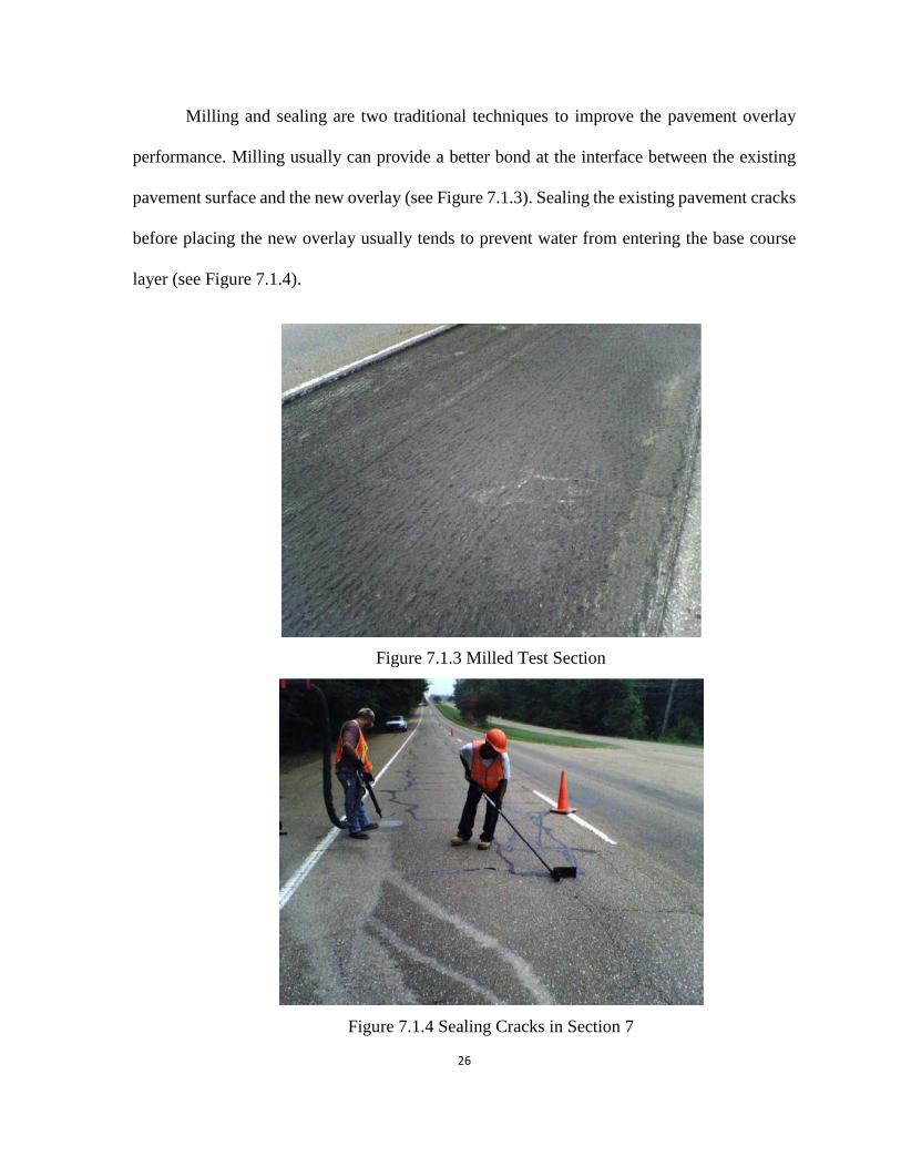
Milling and sealing are two traditional techniques to improve the pavement overlay
performance. Milling usually can provide a better bond at the interface between the existing
pavement surface and the new overlay (see Figure 7.1.3). Sealing the existing pavement cracks
before placing the new overlay usually tends to prevent water from entering the base course
layer (see Figure 7.1.4).
Figure 7.1.3 Milled Test Section
Figure 7.1.4 Sealing Cracks in Section 7

27
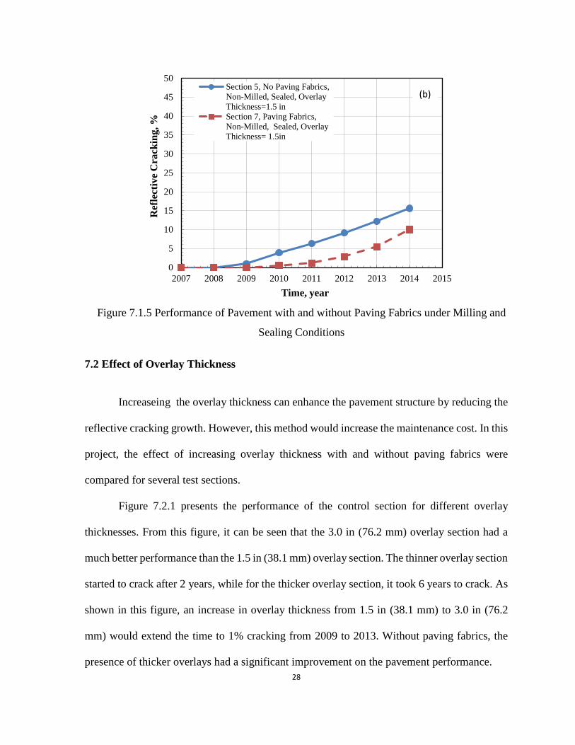
In this project, milling and sealing methods were used in both the control section and
the paving fabrics section to examine the performance of paving fabrics with milling and
sealing methods. As shown in Figure 7.1.5(a), the paving fabric section over the milled
section performed considerably better than the control section. The paving fabric section
started cracking in 2012, three years later than the control section. By 2014, the paving fabric
section had substantially less cracking than the control section (5% for the paving fabric
section compared to 48% for the control section). Figure 7.1.5 (b) compares the performance
of the pavement section with and without paving fabrics under sealing condition. As shown
in this figure, the addition of paving fabrics delayed and reduced the reflective cracking. By
2014, the paving fabric section (10% cracking) had 5% less cracking than the control section
(15% cracking). These results indicated that the paving fabrics sections still functioned well
under milling and sealing conditions.
0
5
10
15
20
25
30
35
40
45
50
2007 2008 2009 2010 2011 2012 2013 2014 2015
Ref
lect
ive
Cra
ckin
g, %
Time, year
Section 1, No Paving Fabrics,
Milled, Non-Sealed, Overlay
Thickness=1.5 inSection 2, Paving Fabrics,
Milled, Non-Sealed, Overlay
Thickness= 1.5in
(a)
28
Figure 7.1.5 Performance of Pavement with and without Paving Fabrics under Milling and
Sealing Conditions
7.2 Effect of Overlay Thickness
Increaseing the overlay thickness can enhance the pavement structure by reducing the
reflective cracking growth. However, this method would increase the maintenance cost. In this
project, the effect of increasing overlay thickness with and without paving fabrics were
compared for several test sections.
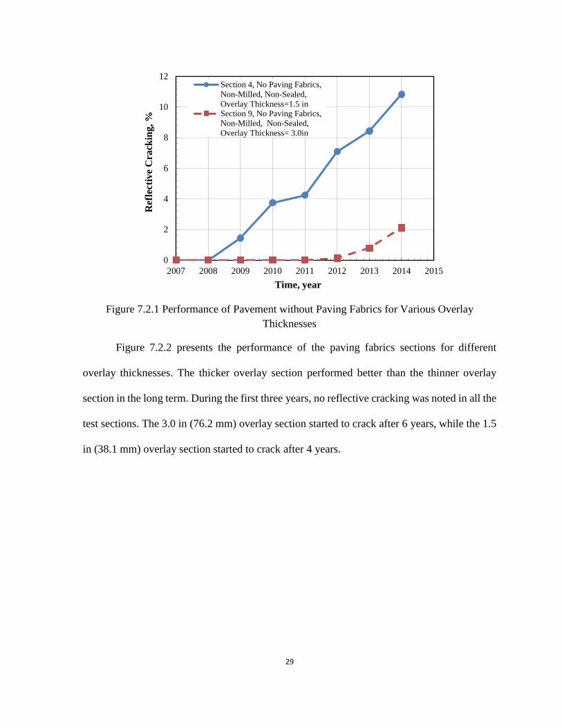
Figure 7.2.1 presents the performance of the control section for different overlay
thicknesses. From this figure, it can be seen that the 3.0 in (76.2 mm) overlay section had a
much better performance than the 1.5 in (38.1 mm) overlay section. The thinner overlay section
started to crack after 2 years, while for the thicker overlay section, it took 6 years to crack. As
shown in this figure, an increase in overlay thickness from 1.5 in (38.1 mm) to 3.0 in (76.2
mm) would extend the time to 1% cracking from 2009 to 2013. Without paving fabrics, the
presence of thicker overlays had a significant improvement on the pavement performance.
0
5
10
15
20
25
30
35
40
45
50
2007 2008 2009 2010 2011 2012 2013 2014 2015
Ref
lect
ive
Cra
ckin
g, %
Time, year
Section 5, No Paving Fabrics,
Non-Milled, Sealed, Overlay
Thickness=1.5 in
Section 7, Paving Fabrics,
Non-Milled, Sealed, Overlay
Thickness= 1.5in
(b)
29
Figure 7.2.1 Performance of Pavement without Paving Fabrics for Various Overlay
Thicknesses
Figure 7.2.2 presents the performance of the paving fabrics sections for different
overlay thicknesses. The thicker overlay section performed better than the thinner overlay
section in the long term. During the first three years, no reflective cracking was noted in all the
test sections. The 3.0 in (76.2 mm) overlay section started to crack after 6 years, while the 1.5
in (38.1 mm) overlay section started to crack after 4 years.
0
2
4
6
8
10
12
2007 2008 2009 2010 2011 2012 2013 2014 2015
Ref
lect
ive
Cra
ckin
g, %
Time, year
Section 4, No Paving Fabrics,
Non-Milled, Non-Sealed,
Overlay Thickness=1.5 inSection 9, No Paving Fabrics,
Non-Milled, Non-Sealed,
Overlay Thickness= 3.0in

30
Figure 7.2.2 Performance of Pavement with Paving Fabrics for Various Overlay Thicknesses
Figure 7.2.3 shows the performance of pavements with paving fabrics for different
overlay thicknesses under milling condition. As shown in this figure, the trends for both curves
are essentially the same. Nevertheless, the 1.5 in (38.1 mm) overlay section started to crack
one year later than the 3.0 in (76.2 mm) overlay section. However, there was no significant
difference between the 1.5 in (38.1 mm) overlay (with paving fabrics) section and the 3.0 in
(76.2 mm) overlay section during the first 8 years. The increase in overlay thickness on milled
section did not influence the reflective cracking.
0
2
4
6
8
10
12
2007 2008 2009 2010 2011 2012 2013 2014 2015
Ref
lect
ive
Cra
ckin
g, %
Time, year
Sections 6&8 (Average), Paving
Fabrics, Non-Milled, Non-Sealed,
Overlay Thickness=1.5 in
Sections 10&12 (Average), Paving
Fabrics, Non-Milled, Non-Sealed,
Overlay Thickness= 3.0in
31
Figure 7.2.3 Performance of Pavement with Paving Fabrics and Milling Method for Various
Overlay Thicknesses
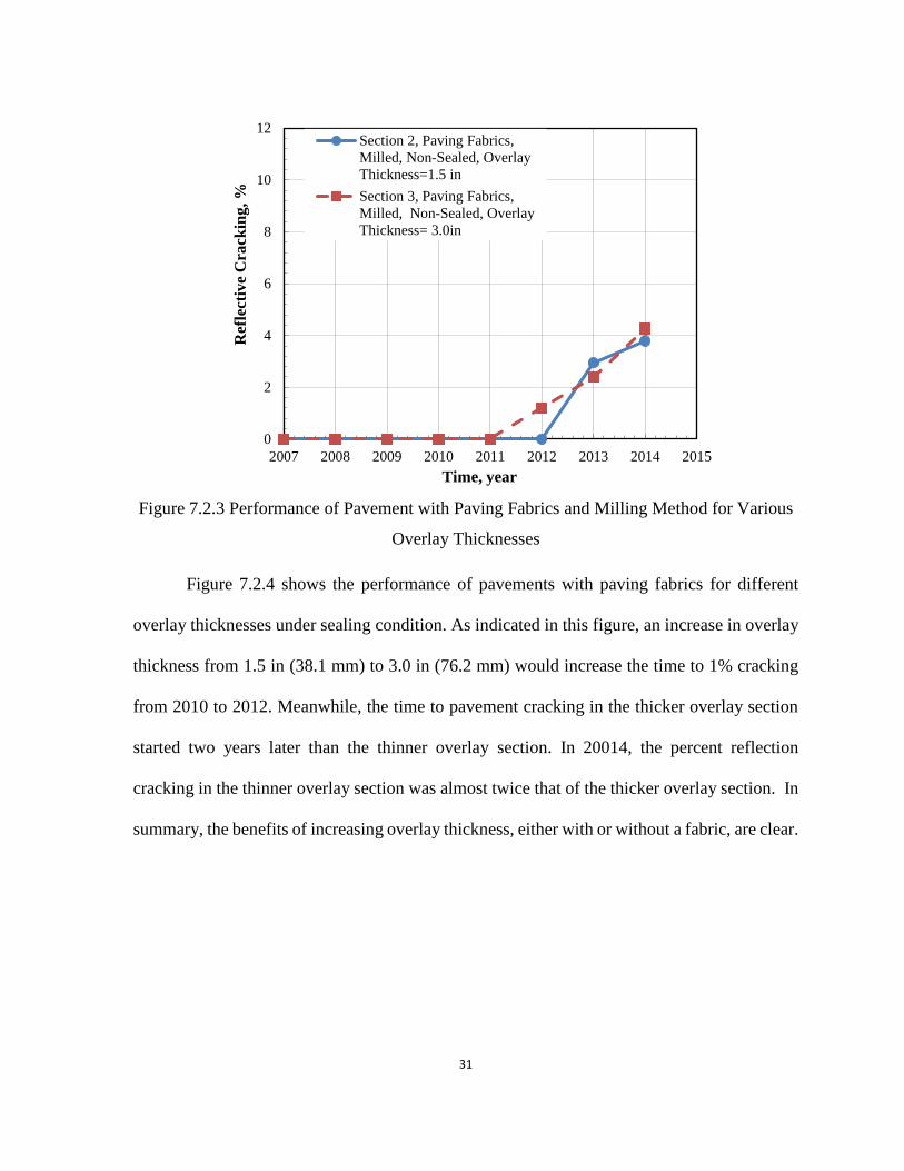
Figure 7.2.4 shows the performance of pavements with paving fabrics for different
overlay thicknesses under sealing condition. As indicated in this figure, an increase in overlay
thickness from 1.5 in (38.1 mm) to 3.0 in (76.2 mm) would increase the time to 1% cracking
from 2010 to 2012. Meanwhile, the time to pavement cracking in the thicker overlay section
started two years later than the thinner overlay section. In 20014, the percent reflection
cracking in the thinner overlay section was almost twice that of the thicker overlay section. In
summary, the benefits of increasing overlay thickness, either with or without a fabric, are clear.
0
2
4
6
8
10
12
2007 2008 2009 2010 2011 2012 2013 2014 2015
Ref
lect
ive
Cra
ckin
g, %
Time, year
Section 2, Paving Fabrics,
Milled, Non-Sealed, Overlay
Thickness=1.5 in
Section 3, Paving Fabrics,
Milled, Non-Sealed, Overlay
Thickness= 3.0in
32
Figure 7.2.4 Performance of Pavement with Paving Fabrics and Sealing Method for Various
Overlay Thicknesses
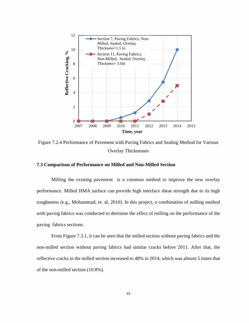
7.3 Comparison of Performance on Milled and Non-Milled Section
Milling the existing pavement is a common method to improve the new overlay
performance. Milled HMA surface can provide high interface shear strength due to its high
roughnness (e.g., Mohammad, et. al, 2010). In this project, a combination of milling method
with paving fabrics was conducted to detrmine the effect of milling on the performance of the
paving fabrics sections.
From Figure 7.3.1, it can be seen that the milled section without paving fabrics and the
non-milled section without paving fabrics had similar cracks before 2011. After that, the
reflective cracks in the milled section increased to 48% in 2014, which was almost 5 times that
of the non-milled section (10.8%).
0
2
4
6
8
10
12
2007 2008 2009 2010 2011 2012 2013 2014 2015
Ref
lect
ive
Cra
ckin
g, %
Time, year
Section 7, Paving Fabrics, Non-
Milled, Sealed, Overlay
Thickness=1.5 in
Section 11, Paving Fabrics,
Non-Milled, Sealed, Overlay
Thickness= 3.0in

33
7.3.1 Performance of Pavement without Paving Fabrics under Milling Method
Figure 7.3.2 provides the effect of milling on the performance of pavements with
paving fabrics for 1.5 in (38.1 mm) and 3.0 in (76.2 mm) overlay thickness. In Figure 7.3.2 (a),
the milled section started to crack in 2013, while the non-milled section cracked in 2011. The
performance of the milled section was better than the non-milled section between 2007 and
2012. After 2012, these two sections almost had the same reflective cracking in the new overlay
surface. One year later in 2014, after seven years, the reflective cracking in the non-milled
section increased to 4.4%, while for the milled section, the cracking increased to approximately
4%. As shown in Figure 7.3.2 (b), the milled section started cracking in 2012, while for the
non-milled section, the cracking started in 2013. After 2011, the milled section started to crack
and the reflective cracking increased to 4.3% by 2014. The non-milled section had less than 1%
cracking by 2014.
0
10
20
30
40
50
60
2007 2008 2009 2010 2011 2012 2013 2014 2015
Ref
lect
ive
Cra
ckin
g, %
Time, year
Section 4, No Paving Fabrics,
Non-Milled, Non-Sealed,
Overlay Thickness=1.5 inSection 1, No Paving Fabrics,
Milled, Non-Sealed, Overlay
Thickness=1.5 in

34
Figure 7.3.2 Performance of Pavement with Paving Fabrics under Milling Method, (a) 1.5 in
(38.1 mm) Overlay Thickness; (b) 3.0 in (76.2 mm) Overlay Thickness
In this case, the milling technique did not have a significant improvement on the
performance of paving fabric sections, and for the thicker overlay section, the performance of
the milled section was even worse than the non-milled section. This may be explained by the
0
1
2
3
4
5
6
7
8
9
10
2007 2008 2009 2010 2011 2012 2013 2014 2015
Ref
lect
ive
Cra
ckin
g, %
Time, year
Sections 6&8 (Average), Paving
Fabrics, Non-Milled, Non-Sealed,
Overlay Thickness=1.5 in
Section 2, Paving Fabrics, Milled, Non-
Sealed, Overlay Thickness=1.5 in
0
1
2
3
4
5
6
7
8
9
10
2007 2008 2009 2010 2011 2012 2013 2014 2015
Ref
lect
ive
Cra
ckin
g, %
Time, year
Sections 10&12 (Average), Paving
Fabrics, Non-Milled, Non-Sealed,
Overlay Thickness=3.0 inSection 3, Paving Fabrics, Milled,
Non-Sealed, Overlay Thickness=3.0
in
(a)
(b)
35
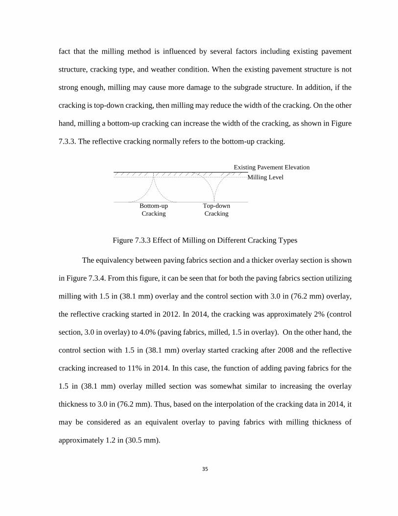
fact that the milling method is influenced by several factors including existing pavement
structure, cracking type, and weather condition. When the existing pavement structure is not
strong enough, milling may cause more damage to the subgrade structure. In addition, if the
cracking is top-down cracking, then milling may reduce the width of the cracking. On the other
hand, milling a bottom-up cracking can increase the width of the cracking, as shown in Figure
7.3.3. The reflective cracking normally refers to the bottom-up cracking.
Bottom-up
Cracking
Top-down
Cracking
Milling Level
Existing Pavement Elevation
Figure 7.3.3 Effect of Milling on Different Cracking Types
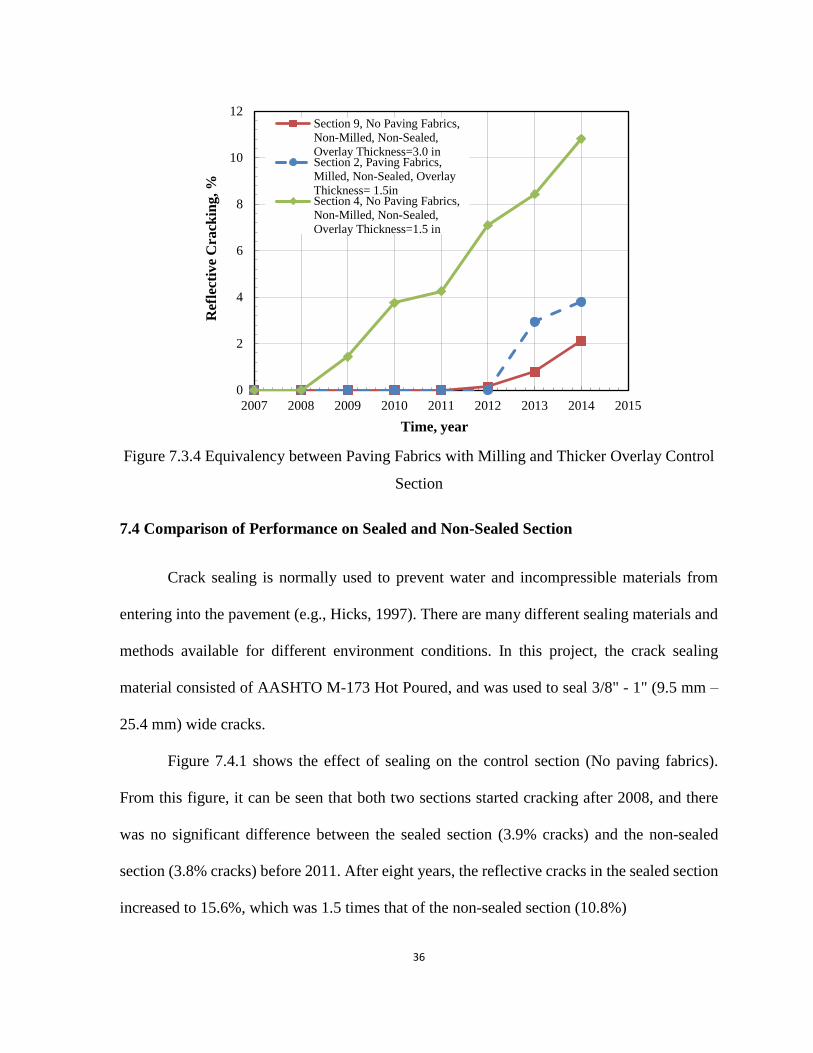
The equivalency between paving fabrics section and a thicker overlay section is shown
in Figure 7.3.4. From this figure, it can be seen that for both the paving fabrics section utilizing
milling with 1.5 in (38.1 mm) overlay and the control section with 3.0 in (76.2 mm) overlay,
the reflective cracking started in 2012. In 2014, the cracking was approximately 2% (control
section, 3.0 in overlay) to 4.0% (paving fabrics, milled, 1.5 in overlay). On the other hand, the
control section with 1.5 in (38.1 mm) overlay started cracking after 2008 and the reflective
cracking increased to 11% in 2014. In this case, the function of adding paving fabrics for the
1.5 in (38.1 mm) overlay milled section was somewhat similar to increasing the overlay
thickness to 3.0 in (76.2 mm). Thus, based on the interpolation of the cracking data in 2014, it
may be considered as an equivalent overlay to paving fabrics with milling thickness of
approximately 1.2 in (30.5 mm).
36
Figure 7.3.4 Equivalency between Paving Fabrics with Milling and Thicker Overlay Control
Section
7.4 Comparison of Performance on Sealed and Non-Sealed Section
Crack sealing is normally used to prevent water and incompressible materials from
entering into the pavement (e.g., Hicks, 1997). There are many different sealing materials and
methods available for different environment conditions. In this project, the crack sealing
material consisted of AASHTO M-173 Hot Poured, and was used to seal 3/8" - 1" (9.5 mm –
25.4 mm) wide cracks.
Figure 7.4.1 shows the effect of sealing on the control section (No paving fabrics).
From this figure, it can be seen that both two sections started cracking after 2008, and there
was no significant difference between the sealed section (3.9% cracks) and the non-sealed
section (3.8% cracks) before 2011. After eight years, the reflective cracks in the sealed section
increased to 15.6%, which was 1.5 times that of the non-sealed section (10.8%)
0
2
4
6
8
10
12
2007 2008 2009 2010 2011 2012 2013 2014 2015
Ref
lect
ive
Cra
ckin
g, %
Time, year
Section 9, No Paving Fabrics,
Non-Milled, Non-Sealed,
Overlay Thickness=3.0 inSection 2, Paving Fabrics,
Milled, Non-Sealed, Overlay
Thickness= 1.5inSection 4, No Paving Fabrics,
Non-Milled, Non-Sealed,
Overlay Thickness=1.5 in

37
7.4.1 Performance of Pavement without Paving Fabrics under Sealing Method
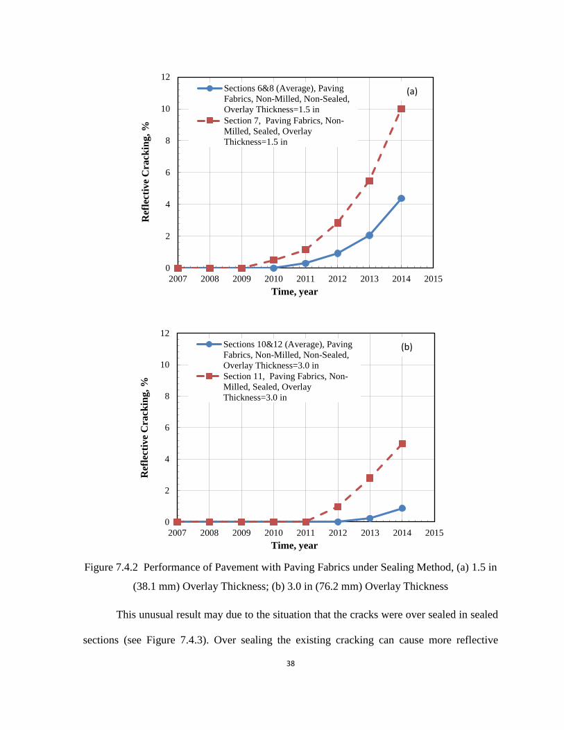
Figures 7.4.2 provides the performance of pavement sections with paving fabrics under
sealing condition for 1.5 in (38.1 mm) and 3.0 in (76.2 mm) overlay thickness. From this figure,
it can be seen that the sealing did not significantly impact the performance of the pavement
with paving fabrics, and the non-sealed section had less cracking than the sealed section. This
was true for both the 1.5 in (38.1 mm) and the 3.0 in (76.2 mm) overlay sections. For the 1.5
in (38.1 mm) section, as shown in in Figure 7.4.2 (a), the sealed section started to crack 2 years
earlier than the non-sealed section, and by 2014, the reflective cracking for the sealed and the
non-sealed sections was 10% and 3%, respectively. For the 3.0 in (76.2 mm) section, as shown
in Figure 7.4.2 (b), the non-sealed section started to crack one year later than the sealed section.
By 2014, the non-sealed section had only 1% reflective cracks, while the sealed section had
approximately 5% reflective cracking. Instead of improving the performance of the pavement,
sealing the existing cracks made it worse in this project.
0
2
4
6
8
10
12
14
16
18
2007 2008 2009 2010 2011 2012 2013 2014 2015
Ref
lect
ive
Cra
ckin
g, %
Time, year
Section 4, No Paving Fabrics,
Non-Milled, Non-Sealed,
Overlay Thickness=1.5 inSection 5, No Paving Fabrics,
Non-Milled, Sealed, Overlay
Thickness=1.5 in
38
Figure 7.4.2 Performance of Pavement with Paving Fabrics under Sealing Method, (a) 1.5 in
(38.1 mm) Overlay Thickness; (b) 3.0 in (76.2 mm) Overlay Thickness
This unusual result may due to the situation that the cracks were over sealed in sealed
sections (see Figure 7.4.3). Over sealing the existing cracking can cause more reflective
0
2
4
6
8
10
12
2007 2008 2009 2010 2011 2012 2013 2014 2015
Ref
lect
ive
Cra
ckin
g, %
Time, year
Sections 6&8 (Average), Paving
Fabrics, Non-Milled, Non-Sealed,
Overlay Thickness=1.5 in
Section 7, Paving Fabrics, Non-
Milled, Sealed, Overlay
Thickness=1.5 in
0
2
4
6
8
10
12
2007 2008 2009 2010 2011 2012 2013 2014 2015
Ref
lect
ive
Cra
ckin
g, %
Time, year
Sections 10&12 (Average), Paving
Fabrics, Non-Milled, Non-Sealed,
Overlay Thickness=3.0 in
Section 11, Paving Fabrics, Non-
Milled, Sealed, Overlay
Thickness=3.0 in
(b)
(a)

39
cracking on the new overlay surface. As shown in Figure 7.4.4, when the existing crack was
over sealed, the contact area between the overlay and sealed materials increased and more
reflective cracking occurred on the overlay surface. In addition, the paving fabrics section had
already higher shear strength, which in turn, resulted in less cracking. In this case, sealing did
not benefit the performance of paving fabrics section.
Figure 7.4.3 Cracks Over-Sealed in Sealed Section
Crack Sealed Crack Over Sealed
Overlay
Existing
Surface Layer
Crack Over SealedCrack Sealed
Overlay
Surface
Figure 7.4.4 Damage of Over Sealed Cracks
The equivalency between paving fabrics section under sealing method and a thicker
overlay section is shown in Figure 7.4.5. The paving fabrics section under sealing method with
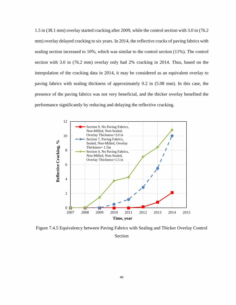
40
1.5 in (38.1 mm) overlay started cracking after 2009, while the control section with 3.0 in (76.2
mm) overlay delayed cracking to six years. In 2014, the reflective cracks of paving fabrics with
sealing section increased to 10%, which was similar to the control section (11%). The control
section with 3.0 in (76.2 mm) overlay only had 2% cracking in 2014. Thus, based on the
interpolation of the cracking data in 2014, it may be considered as an equivalent overlay to
paving fabrics with sealing thickness of approximately 0.2 in (5.08 mm). In this case, the
presence of the paving fabrics was not very beneficial, and the thicker overlay benefited the
performance significantly by reducing and delaying the reflective cracking.
Figure 7.4.5 Equivalency between Paving Fabrics with Sealing and Thicker Overlay Control
Section
0
2
4
6
8
10
12
2007 2008 2009 2010 2011 2012 2013 2014 2015
Ref
lect
ive
Cra
ckin
g, %
Time, year
Section 9, No Paving Fabrics,
Non-Milled, Non-Sealed,
Overlay Thickness=3.0 in
Section 7, Paving Fabrics,
Sealed, Non-Milled, Overlay
Thickness= 1.5in
Section 4, No Paving Fabrics,
Non-Milled, Non-Sealed,
Overlay Thickness=1.5 in

41
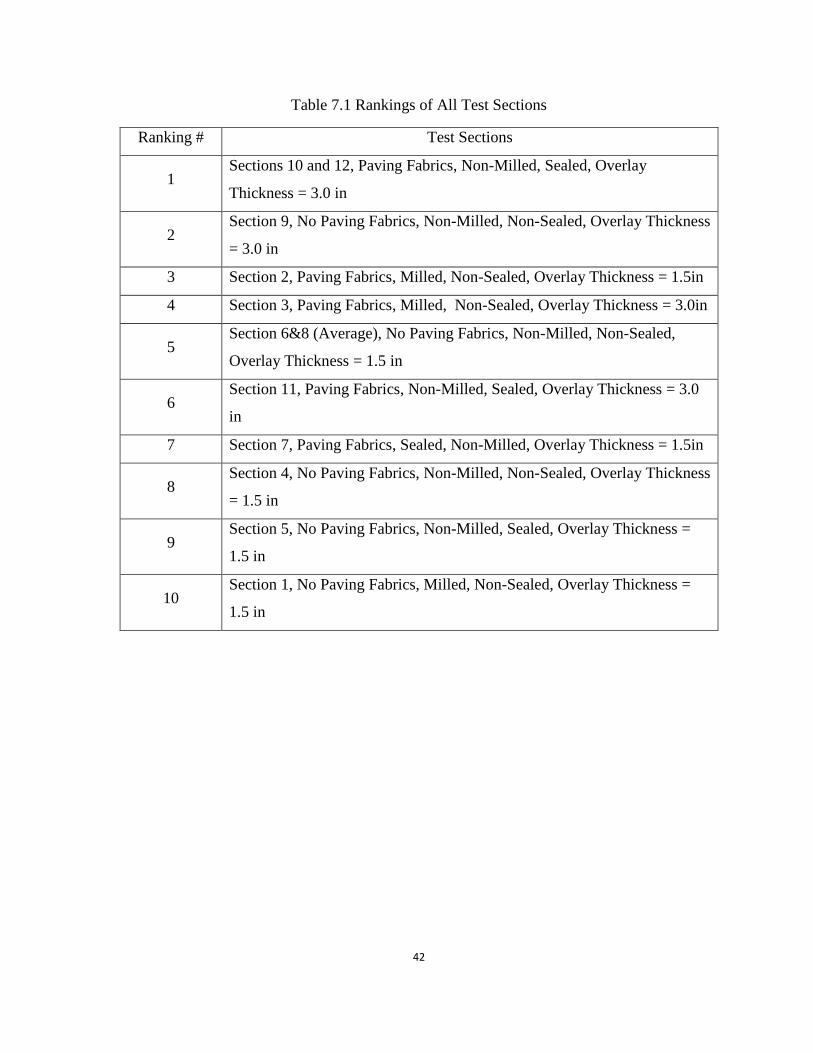
7.5 Summary of the Results for All Test Sections
The results for all sections are summarized in Figure 7.5.1. As shown in this figure,
Sections 10 and 12 had the best performance on reducing the reflective cracking, and there was
only about 1% cracking in 2014. Section 1 (no paving fabrics, milled) had the least effective
performance, and the reflective cracking reached to 48% in 2014. The rankings for all sections
are shown in Table 7.1.
Figure 7.5.1 Summary of All Test Sections
0
5
10
15
20
25
30
35
40
45
50
2007 2008 2009 2010 2011 2012 2013 2014 2015
Ref
lect
ive
Cra
ckin
g, %
Time, year
Section 1, No Paving Fabrics, Milled, Non-
Sealed, Overlay Thickness=1.5 in
Section 2, Paving Fabrics, Milled, Non-
Sealed, Overlay Thickness= 1.5in
Section 3, Paving Fabrics, Milled, Non-
Sealed, Overlay Thickness= 3.0in
Section 4, No Paving Fabrics, Non-Milled,
Non-Sealed, Overlay Thickness=1.5 in
Section 5, No Paving Fabrics, Non-Milled,
Sealed, Overlay Thickness=1.5 in
Sections 6&8 (Average), No Paving Fabrics,
Non-Milled, Non-Sealed, Overlay
Thickness=1.5 inSection 7, Paving Fabrics, Sealed, Non-
Milled, Overlay Thickness= 1.5in
Section 9, No Paving Fabrics, Non-Milled,
Non-Sealed, Overlay Thickness=3.0 in
Sections 10&12 (Average), Paving Fabrics,
Non-Milled, Non-Sealed, Overlay
Thickness=3.0 inSection 11, Paving Fabrics, Non-Milled,
Sealed, Overlay Thickness=3.0 in
42
Table 7.1 Rankings of All Test Sections
Ranking # Test Sections
1 Sections 10 and 12, Paving Fabrics, Non-Milled, Sealed, Overlay
Thickness = 3.0 in
2 Section 9, No Paving Fabrics, Non-Milled, Non-Sealed, Overlay Thickness
= 3.0 in
3 Section 2, Paving Fabrics, Milled, Non-Sealed, Overlay Thickness = 1.5in
4 Section 3, Paving Fabrics, Milled, Non-Sealed, Overlay Thickness = 3.0in
5 Section 6&8 (Average), No Paving Fabrics, Non-Milled, Non-Sealed,
Overlay Thickness = 1.5 in
6 Section 11, Paving Fabrics, Non-Milled, Sealed, Overlay Thickness = 3.0
in
7 Section 7, Paving Fabrics, Sealed, Non-Milled, Overlay Thickness = 1.5in
8 Section 4, No Paving Fabrics, Non-Milled, Non-Sealed, Overlay Thickness
= 1.5 in
9 Section 5, No Paving Fabrics, Non-Milled, Sealed, Overlay Thickness =
1.5 in
10 Section 1, No Paving Fabrics, Milled, Non-Sealed, Overlay Thickness =
1.5 in

43
CHAPTER 8
COSTS-BENEFIT ANALYSIS
8.1 Introduction
Although each DOT spends several millions of dollars each year on reflective cracking
controls systems, the cost effectiveness of these treatments has not been reliably determined.
Life cycle cost analysis (LCCA) is a data-driven tool that provides a detailed account of the
total costs of a project over its expected life. Over the past several years, numerous agencies
and institutions have developed methodologies for pavement life cycle cost analysis, and some
of these organizations have gone a step further to develop computer programs for their LCCA
methodologies to facilitate the analysis (Lamptey, et al., 2005). A summary of current
methodologies for pavement life cycle cost analysis is presented below.
8.2 Summary of Current Methodologies
There are several software programs that can be used to conduct an LCCA. Several
states have developed their own Excel spreadsheets and have made them available online or
by request. If user costs are not considered and a deterministic approach is used, Excel is an
excellent tool for LCCA. If user costs are considered and/or a probabilistic approach is
employed, Excel can still be used, but a few Add-ins would be required (Arash, et al., 2014).
Some common methods based on Excel spreadsheets are described below.
The APA LCCA software is based on a Microsoft Excel spreadsheet, and generally
seems to be more user friendly than most other LCCA software packages. This software
can optimizes work-zone timing to minimize user costs based on the hourly traffic

44
distribution, and updates the values of travel time using the current CPI and the base
CPI. The disadvantage of the APA software is that the software is not flexible for
different alternatives (Arash, et al., 2014).
Idaho’s LCCA software package is an Excel-based program that was tailored largely
to suit conditions in Idaho. This software can use a dynamic graphics feature that
automatically illustrates the layer configuration of a selected pavement design
alternative. In addition, this software can convert units across the English and metric
systems. The shortcoming of this software is that it has a very comprehensive agency
cost input structure. This software is for project-level pavement cost analysis (Lamptey,
et al. 2005).
The American Concrete Paving Association (ACPA) developed a spreadsheet-type
analysis program that is used with Microsoft Excel to analyze both rigid and flexible
pavements. This software contains ‘reliability’ concept, which can determine the total
expected costs over the life cycle with 90% confidence level (Lamptey, et al. 2005).
FHWA’s RealCost software is based on a Microsoft Excel spreadsheet, and is the most
versatile package compared to the other existing LCCA packages. The current version
(v 2.5.0) was developed in 2009. This software program consists of a Microsoft Excel
workbook with additional Visual Basic for Applications (VBA) programming code. It
has a detailed work-zone user costs computation and it is relatively easy to use. In this
study, RealCost was used to analyze the life-cycle cost (Arash, et al., 2014).

45
8.3 Results of Life Cycle Cost Analysis of the Pavement Sections Using RealCost
RealCost was created with two distinct purposes. The first was to provide an
instructional tool for design decision-makers who want to learn about LCCA. The software
allows the user to investigate the effects of cost, service life, and economic inputs on the overall
life-cycle cost. The second purpose was to provide a computational tool for designers to
incorporate life-cycle costs into their roadway infrastructure investment decisions (Federal
Highway Administration, 2010).
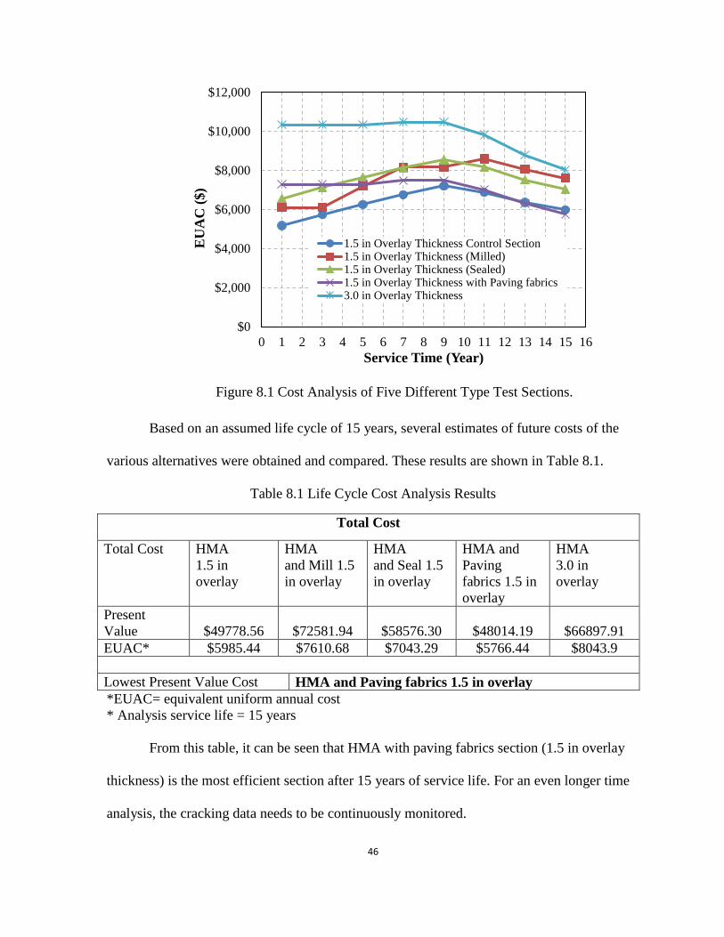
Different stage analysis is shown in Fig. 8.1. From this figure, when the service time
of the pavement is less than 13 years, the equivalent uniform annual cost (EUAC) of the control
section (1.5 in overlay thickness without paving fabrics) is the least, and thus, indicates the
most cost-efficient section. After 13 years, the 1.5 in (38.1 mm) overlay thickness with paving
fabrics became the most cost-efficient section. On the other hand, it may be noted that the
performance of paving fabrics section (3% reflective cracking) is much better than the control
section (11% reflective cracking). Based on this analysis, the performance of the paving fabrics
is more efficient in the long term (>10 years).
46
Figure 8.1 Cost Analysis of Five Different Type Test Sections.
Based on an assumed life cycle of 15 years, several estimates of future costs of the
various alternatives were obtained and compared. These results are shown in Table 8.1.
Table 8.1 Life Cycle Cost Analysis Results
Total Cost
Total Cost HMA
1.5 in
overlay
HMA
and Mill 1.5
in overlay
HMA
and Seal 1.5
in overlay
HMA and
Paving
fabrics 1.5 in
overlay
HMA
3.0 in
overlay
Present
Value $49778.56 $72581.94 $58576.30 $48014.19 $66897.91
EUAC* $5985.44 $7610.68 $7043.29 $5766.44 $8043.9
Lowest Present Value Cost HMA and Paving fabrics 1.5 in overlay
*EUAC= equivalent uniform annual cost
* Analysis service life = 15 years
From this table, it can be seen that HMA with paving fabrics section (1.5 in overlay
thickness) is the most efficient section after 15 years of service life. For an even longer time
analysis, the cracking data needs to be continuously monitored.
$0
$2,000
$4,000
$6,000
$8,000
$10,000
$12,000
0 1 2 3 4 5 6 7 8 9 10 11 12 13 14 15 16
EU
AC
($)
Service Time (Year)
1.5 in Overlay Thickness Control Section1.5 in Overlay Thickness (Milled)1.5 in Overlay Thickness (Sealed)1.5 in Overlay Thickness with Paving fabrics3.0 in Overlay Thickness

47
CHAPTER 9
CORING
In this project, Burns Cooley Dennis, Inc. conducted full depth asphalt pavement coring
prior to pavement rehabilitation and at four and seven years after construction. For each
examination period, three cores were obtained within each of the twelve test sections for a total
of thirty-six cores. Individual pavement layers of each core were measured to determine
thickness, and were also visually examined to determine the level of moisture damage present.
Moisture damage was categorized into six levels (1-none, 2-low, 3-low/moderate, 4-moderate,
5-moderate/high, 6-high, 7-Asphalt layer was not recovered intact). The moisture damage level
for each section was visually determined. The effect of paving fabrics systems on moisture
damage is discussed below.
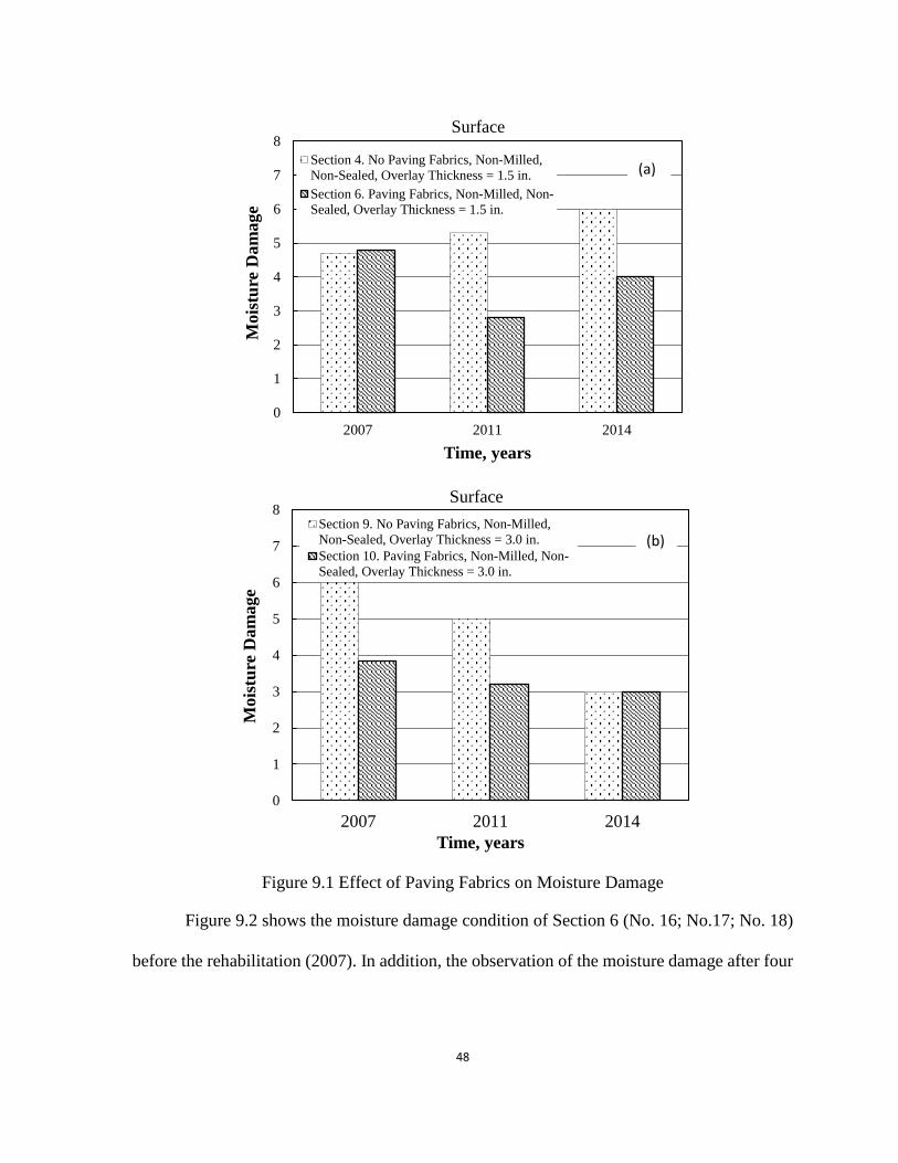
Figure 9.1 compares the moisture damage between Section 4 and Section 6. Figure 9.1
(a) shows that with 1.5 in (38.1 mm) overlay thickness, Section 4 and Section 6 had similar
moisture damage in 2007. After four years, the moisture damage of Section 6 was less than
that of the Section 4, and the same trend was noted after seven years. Section 4 showed an
increase in moisture damage level with time, whereas the presence of paving fabric reduced
moisture damage for the 1.5 in. (38.1 mm) overlay section. Figure 9.1 (b) shows the same
comparison for the 3.0 in (76.2 mm) sections. The results from both Section 9 and Section 10
indicated that the moisture damage decreased after seven years. In thicker overlay section, the
presence of paving fabric did not show a significant improvement in moisture damage. From
these results, it may be concluded that there is no increase in moisture damage level in the
presence of paving fabric.
48
Figure 9.1 Effect of Paving Fabrics on Moisture Damage
Figure 9.2 shows the moisture damage condition of Section 6 (No. 16; No.17; No. 18)
before the rehabilitation (2007). In addition, the observation of the moisture damage after four
0
1
2
3
4
5
6
7
8
2007 2011 2014
Mois
ture
Dam
age
Time, years
Surface
Section 4. No Paving Fabrics, Non-Milled,
Non-Sealed, Overlay Thickness = 1.5 in.
Section 6. Paving Fabrics, Non-Milled, Non-
Sealed, Overlay Thickness = 1.5 in.
0
1
2
3
4
5
6
7
8
2007 2011 2014
Mois
ture
Dam
age
Time, years
Surface
Section 9. No Paving Fabrics, Non-Milled,
Non-Sealed, Overlay Thickness = 3.0 in.
Section 10. Paving Fabrics, Non-Milled, Non-
Sealed, Overlay Thickness = 3.0 in.
(a)
(b)

49
years and seven years is shown in Figures 9.3 and 9.4, respectively. Additional pictures about
other sections are included in Appendix II.
Figure 9.2 Coring Sample at Section 6 in 2007
Figure 9.3 Coring Sample at Section 6 in 2011
Figure 9.4 Coring Sample at Section 6 in 2014

50
CHAPTER 10
SUMMARY AND CONCLUSIONS
In this project, a comprehensive testing, monitoring, and analysis program was
undertaken, where twelve 500-ft (152.4 m) pavement sections of a four-lane highway were
rehabilitated, and then monitored for seven years. Particular attention was directed towards
investigating the influence of several factors including overlay thickness on long-term
performance of paving fabric sections. A comparison between the performance of paving
fabric treatment systems for milled and non-milled surfaces, as well as a comparison between
the performance of paving fabrics on sealed and non-sealed surfaces was conducted. As a result
of this study, the following conclusions can be made.
1. The addition of paving fabrics significantly improved the long-term performance of
pavements. This was also true under milling and sealing conditions.
2. Based on the analysis of the equivalency between paving fabrics section and a thicker
overlay section, an equivalent overlay to paving fabrics thickness of approximately 1.2
in (30.5 mm); an equivalent overlay to paving fabrics over milling thickness of
approximately 1.2 in (38.1 mm) and an equivalent overlay to paving fabrics over
sealing thickness of approximately 0.2 in (5.1 mm) may be considered.
3. Increasing overlay thickness, either with or without a fabric, significantly enhanced the
long-term performance of the pavement sections.
4. The milling technique did not have a significant improvement on the performance of
paving fabric sections, and for the thicker overlay section, the performance of milled
section was even worse than the non-milled section.
51
5. The sealing technique did not considerably impact the performance of pavement with
paving fabrics, and the non-sealed section had less cracking than the sealed section.
This was true for both the 1.5 in (38.1 mm) and the 3.0 in (76.2 mm) overlay sections.
6. When the service time of the pavement is less than 13 years, the equivalent uniform
annual cost (EUAC) of the control section (1.5 in overlay thickness without paving
fabrics) is the least, and thus, indicates the most cost-efficient section. After 13 years,
the 1.5 in (38.1 mm) overlay thickness with paving fabrics became the most cost-
efficient section. On the other hand, it may be noted that the performance of paving
fabrics section (3% reflective cracking) is much better than the control section (11%
reflective cracking). Based on this analysis, the performance of the paving fabrics is
more efficient in the long term.
This project provided a fundamental understanding of the behavior of paving fabric
systems to reduce reflective cracking, and offered practicing engineers a valuable alternative
for more effective schemes during pavement rehabilitation strategies.

52
REFERENCES
1. AASHTO M 288 (1993). “Specification for Geotextiles Used for Subsurface Drainage
Purposes”, AASHTO, Washington, D.C.
2. Ahlrich, R. C. (1986). “Evaluation of Asphalt Rubber and Engineering Fabrics as
Pavement Interlayers,” Final Report, Miscellaneous Paper GL-86-34, U.S. Army Corps
of Engineers, Waterways Experiment Station, Vicksburg, MS, Nov.
3. Amini, F. (2005). “Potential Applications of Paving Fabrics to Reduce Reflective
Cracking”, Final Report, Report No. FHWA/MS-DOT-RD-05-174, Jackson State
University, Department of Civil & Environmental Engineering, Jackson, MS.
4. Amini, F, and Turnquest, B. (2008). “Construction Monitoring of Paving Fabrics
Systems to Reduce Reflective Cracking”, Final Report, Report No. FHWA/MS-DOT-
RD-08-148, Jackson State University Department of Civil & Environmental
Engineering, Jackson, MS.
5. Amini, F, Turnquest, B., and Ahlrich, R. (2012). “Construction Monitoring of Paving
Fabrics Systems to Reduce Reflective Cracking.” International Journal of Emerging
Technology and Advanced Engineering, Vol. 2, No. 6, pp. 413-420.
6. Arash S., Magdy, A., and Anthony, W. (2014). “Tools for Sustainability Management
in Pavement Industry”, Journal of Frontiers in Construction Engineering, Vol. 3, Iss. 3,
PP. 55-71.
7. ASTM, (2012). “Standard Test Method for Determining Apparent Opening Size of a
Geotextile”, D4751-12, ASTM International, West Conshohocken, PA.
8. ASTM, (2015). “Standard Test Method for Grab Breaking Load and Elongation of
Geotextiles”, D4632 / D4632M-15a, ASTM International, West Conshohocken, PA.
9. ASTM, (2015). “Standard Test Method for Trapezoid Tearing Strength of Geotextiles”,
D4533 / D4533M-15, ASTM International, West Conshohocken, PA.
10. ASTM, (2015). “Standard Test Methods for Water Permeability of Geotextiles by
Permittivity”, D4491 / D4491M-15, ASTM International, West Conshohocken, PA.
11. ASTM, (2016). “Standard Guide for Identification, Storage, and Handling of
Geosynthetic Rolls and Samples”, D4873 / D4873M-16, ASTM International, West
Conshohocken, PA.
12. Baker, T. (1998). “The Most Overlooked Factor in Paving-Fabric Installation,”
Geotechnical Fabrics Report, Vol. 16, No. 3, pp. 48-52.
53
13. Barazone, M. (2000). “Installing Paving Synthetics-an Overview of Correct Installation
Procedures (Part One),” Geotechnical Fabrics Report, Vol. 18, No. 2, pp. 16-18.
14. Barazone, M. (1990). “Paving Fabric Interlayer Membranes and Installation
Procedures Over the Past 20 Years,” Geotechnical Fabrics Report, Vol. 10, No. 4, pp.
16-21.
15. Barksdale, R. D. (1991). “Fabrics in Asphalt Overlays and Pavement Maintenance,”
Transportation Research Board, Report No. NCHRP 171, Washington, D.C.
16. Brown, D. (2000). “Debate on Road Waterproofing,” World Highways, Vol. 9, No. 2,
pp. 57-59.
17. Brown, N. R. (2003). “Solution for Distressed Pavements and Crack Reflection,”
Transportation Research Record, No. 1819, pp. 313-317.
18. Burmania, D. (1988). “Geotextiles May Bolster Pavement Performance,” Roads &
Bridges, Vol. 26, No. 1, pp. 88-93.
19. Buttlar, W. G., Bozkurt, D., and Dempsey, B. J. (1999). “Evaluation of Reflective
Crack Control Policy,” Final Report, Report No. ITRC FR 95/96-4, Illinois
Transportation Research Center, Edwardsville, IL, p. 184.
20. Button, J. W., and Epps, J. A. (1983). “Evaluation of Mirafi Fabrics for Pavement
Overlays,” Texas Transportation Institute, Final Report 3424-6.
21. Cleveland, G. S., Button, J. W., and Lytton, R .L. (2002). “Geosynthetics in Flexible
and Rigid Pavement Overlay Systems to Reduce Reflection Cracking”. Report No.
FHWA/TX-02/1777. Texas Department of Transportation Research and Technology
Implementation Office, pp. 1–297.
22. Dempsey, B. J. (2002). “Development and Performance of Interlayer Stress-Absorbing
Composite in Asphalt Concrete Overlays,” Transportation Research Record 1809, pp.
175-183.
23. Federal Highway Administration (2010). Life-Cycle Cost Analysis, RealCost User
Manual, Reston, VA
24. Hicks, R., Dunn K., and Moulthrop, J. (1997). “Framework for Selecting Effective
Preventive Maintenance Treatments for Flexible Pavements,” Transportation Research
Record, No. 1597.
25. Holtz, R. D., Christopher, B. R. and Berg, R. R. (1997). “Geosynthetic Engineering,”
BiTech Publishers Ltd., Canada.

54
26. Hughes, J. J., and Somers, E. (2000). “Geogrid Mesh for Reflective Crack Control in
Bituminous Overlays,” Final Report, Report No. PA 200-013-86-001, Pennsylvania
Department of Transportation.
27. Jackson, R. D. (1980). “Use of Fabrics and Other Measures for Reflective Cracking of
Alphabetic Concrete Overlays,” Final Report, Report No. WES/MP/GL-80-2,
FAA/RD-80/8, Waterways Experiment Station, Corps of Engineers, Vicksburg, MS.
28. Jayawickrama, P. W. and Lytton, R. L. (1987). “Methodology for Predicting Asphalt
Concrete Overlay Life Against Reflection Cracking,” Proc. of the Sixth Inter.
Conference on Structural Design of Pavements, Ann Arbor, Michigan, pp. 912-924.
29. Khodaii1 A., and Fallah, S. (2009). “Effects of Geosynthetic Reinforcement on the
Propagation of Reflection Cracking in Asphalt Overlays,” International Journal of Civil
Engineering. Vol. 7, No. 2, pp. 131-140.
30. Koerner, R. (2005). Designing with Geosynthetic, Fifth ed. Prentice Hall, Upper Saddle,
New Jersey.
31. Kutuk, B. (1998). “Performance of Flexible Pavements Reinforced with Geogrids,”
Department of Civil and Environmental Engineering, West Virginia University,
Morgantown, West Virginia.
32. Lamptey, G., Ahmad, M. Z., Labi, S., and Sinha, K. C. (2005). “Life Cycle Cost
Analysis for INDOT Pavement Design Procedures”, Final Report, Report No.
FHWA/IN/JTRP-2004/28, INDOT Division of Research.
33. Lytton, R. L. (1989). “Use of Geotextiles for Reinforcement and Strain Relief in
Asphalt Concrete,” Geotextiles and Geomembranes, Vol. 8, No. 3, pp. 217-237.
34. Marienfeld, M. L. and Baker, T. L. (1999). “Paving Fabric Interlayer as a Pavement
Moisture Barrier,” TRB Circular No. E-C006.
35. Mascunana, I. (1981). “An Evaluation of Engineering Fabric in Pavement
Rehabilitation (IHD-21),” Final Report, Physical Research Report No. 88, Illinois
Department of Transportation.
36. Maurer, D. A. (1985). “Comparison of Methods to Retard Reflective Cracking in
Bituminous Concrete Using Fabrics and Fibers,” Report No. FHWA-PA-85-015,
Pennsylvania Department of Transportation.
37. Maurer, D. A. and Malashekie, G. J. (1989). “Field Performance of Fabrics and Fibers
to Retard Reflective Cracking,” Transportation Research Record, No. 1248, pp. 13-23.

55
38. McGhee, K. H. (1975). “Efforts to Reduce Reflective Cracking of Bituminous Concrete
Overlays of Portland Cement Concrete Pavements,” VHTRC 76-R20, Virginia
Highway and Transportation Research Council, Charlottesville, VA, Nov.
39. Mohammad, L. N., Bae, A., Elseifi, M. A., Button, J., and Patel, N. (2010). “Effects of
Pavement Surface Type and Sample Preparation Method on Tack Coat Interface Shear
Strength,” Transportation Research Record, Journal of the Transportation Research
Board, No. 2180, pp. 93–101.
40. Paris, P. C., and Erdogan, F. A. (1963). “Critical Analysis of Crack Propagation Laws,”
Transactions of ASME, Journal of Basic Engineering, Series D, 85, No. 3, pp. 528-534.
41. Rahman, M., Scofield, L., and Wolf, T. (1989). “Paving Fabrics for Reducing
Reflective Cracking,” Report No. FHWA-AZ-8801, Arizona Transportation Research
Center, Prepared for Arizona Department of Transportation.
42. Roads & Bridges (1989). “Specifier’s Guide to Paving Fabrics,” Vol. 27, No. 5, pp. 75.
43. Shukla S. K., and Yin, J. H. (2004). “Functions and Installation of Paving
Geosynthetics,” Proceedings of the 3rd Asian Regional Conference on Geosynthetics,
Seoul, S. Korea, pp. 314–321.
44. Strategic Highway Research Program (1993). Distress Identification Manual for the
Long-Term Pavement Performance Project, Washington, DC.
45. Sprague, C. J., Allen, S., and Tribbett, W. (1998). “Tensile Properties of Asphalt
Overlay Geosynthetic Reinforcement,” Transportation Research Record, No. 1611, pp.
65-69.
46. Suits, L. D., and Richardson, G. N. (1998). “The Updated AASHTO Geotextile
Specifications,” Geotechnical Fabrics Report, Vol. 16, No. 2, pp. 39-41.
47. Suits, L. D. (1999). “Wrapping up the 1999 TRB Meeting,” Geotechnical Fabrics
Report, Vol. 17, No. 2, pp. 14-15.
48. Suits, L. D. (2001). “AASHTO NTPEP and Specification M-288 for Geotextiles,”
Geotechnical Fabrics Report, Vol. 19, No. 5, pp. 20-25
49. Synthetics Industries (2003). “Pave-Dry Nonwoven Asphalt Overlay Fabrics,” SI
Geosolutions Publication.

56
Appendix I
Site Map
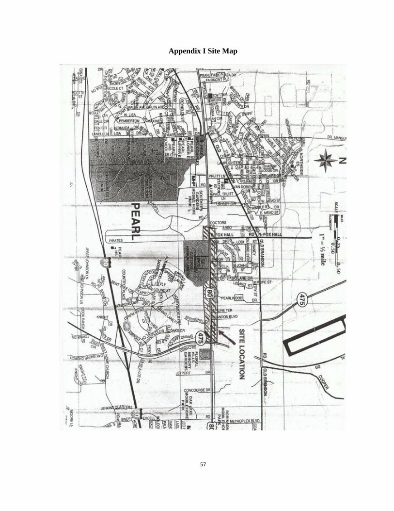
57
Appendix I Site Map
58
Appendix II
Coring Samples
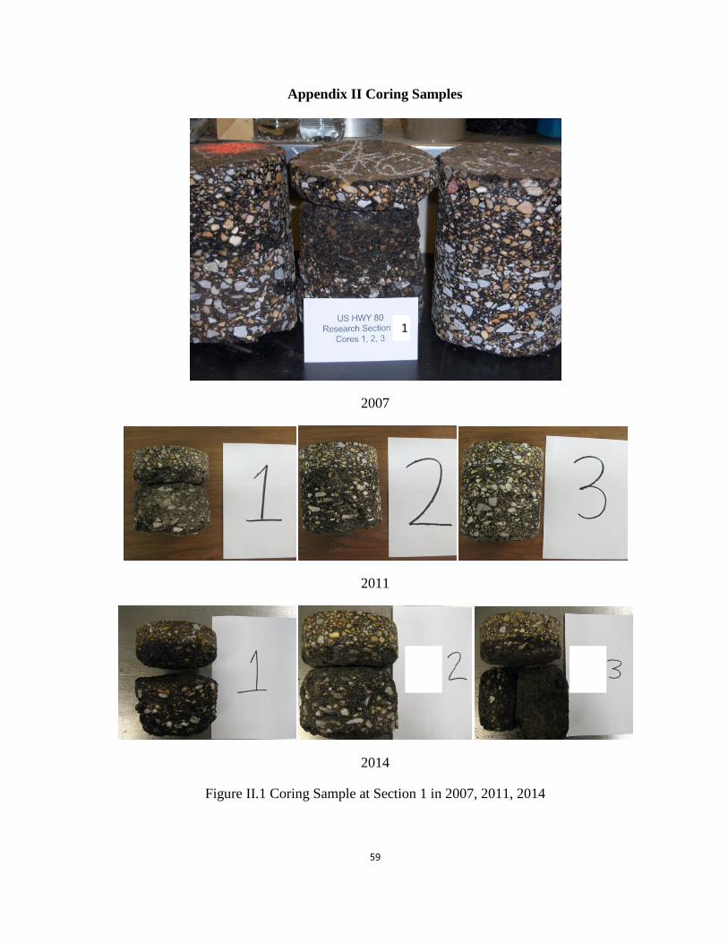
59
Appendix II Coring Samples
2007
2011
2014
Figure II.1 Coring Sample at Section 1 in 2007, 2011, 2014
1
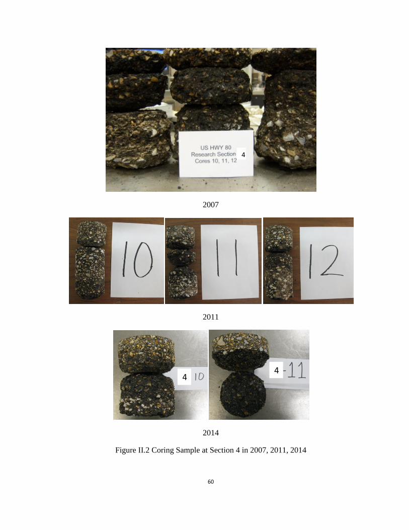
60
2007
2011
2014
Figure II.2 Coring Sample at Section 4 in 2007, 2011, 2014
4
4 4
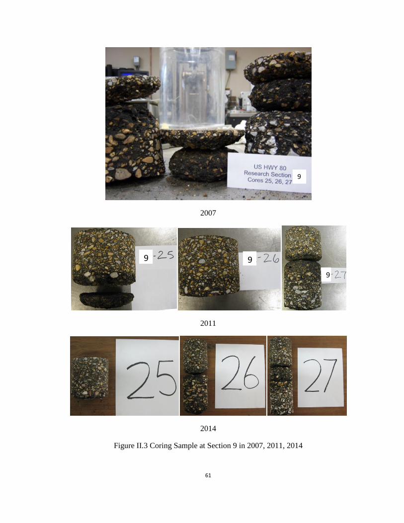
61
2007
2011
2014
Figure II.3 Coring Sample at Section 9 in 2007, 2011, 2014
9
9
9
9

62
2007
2011
2014
Figure II.4 Coring Sample at Section 10 in 2007, 2011, 2014
10
10 10 10