long term analysis of cables problems in egyptian ... · problems in egyptian distribution network...
TRANSCRIPT

Long Term Analysis of Cables Problems in Egyptian Distribution Network
Mohamed Shebl El-Bages, Mousa A. Abd-Allah, and M. Z. A. Elhawary
Electrical Engineering Dept., Faculty of Engineering at Shoubra,
Benha University, Egypt
Abstract: In the last few decades the main focus of utility companies has been on developing diagnostic, location and pin pointing techniques for medium and high voltage cables, despite the fact that most of the installed cable assets on the network consist of low voltage cable. Egyptian distribution network is very complex network and has large lengths of underground cables, which mostly oil paper cables and XLPE cables. The network suffers from an increasingly faults at cable joints, where the main cause is the difficulty of oil paper cable joints which required a skilful technician. Large efforts are spent to categorize the types of faults happen at the cable joints to describe the avoiding methods of these faults. Benefits will be saving of operation cost, time and improvement of system availability and performance to avoid service outage which is a big lost for company and customer. Keyword s: underground cable, testing devices, location methods, fault detection
1. Introduction The location of faults on Egyptian medium voltage (MV) cable networks has plagued electricity supply engineers for many years. Fault location techniques used on high voltage (HV) cables cannot generally be applied to MV distribution cables due to the multi-branched design of MV networks and the difficulty of disconnecting all the customers supplied from the faulty cable. The high operating stress in MV cable insulation result many faults, exhibiting an unstable/nonlinear characteristic making them only locatable when the cable is energized at normal working voltage.
Figure 1. Rate of cable faults at different regions
International Journal on Electrical Engineering and Informatics - Volume 5, Number 2, June 2013
Received: November 17th, 2012. Accepted: May 14th, 2013
154
Although MV cable fault location presents severe technical challenges, network operators require the equipment and procedures used by field staff to be simple. At the same time, incentives imposed by the Regulator have increased the urgency to restore supplies after permanent faults and to avoid outages by reducing the incidence of intermittent faults. The ability to determine all kind of different faults with widely different fault characteristics is depend on the operator's skills by turning on the suitable measuring equipment and the ability to use it. Figure 1 shows the increasing rate of MV cable faults at different regions in the Egyptian distribution network and shows the importance of increasing the different skills to decreasing CML factor (Customer Minutes Lost is a method of measuring the performance of the network). The recording faults are taken in four different regions in the Great Cairo area where, KH is Al-Khanka region, MR is Al-Marg region, HE is Al-Helmia region and MT is Al-Mataria region. The recorded number of faults in KH, MR, HE, and MT regions in 2011 are 258, 450, 194 and 217 respectively.
2. Testing Devices The testing devices used in this study are a high voltage device, VLF device with testing connection output, an impulse voltage device, Teleflex device, arc stabilizing unit, audio frequency generator, burning and testing unit, audio frequency receiver, digiphone or measurement device and cable identifying generator. The testing voltage applied should be less than the allowable voltage according to Eq.(1) to avoid more insulation failure .
6.065.1]1000)32[( xxvoltagexoperatingorvoltageTesting += (1) 3. Results and Discussions Time Domain Reflection (TDR) technique is applied to determine the total length of a cable, the location of low resistive cable faults, the location of cable interruptions and the location of the joints along the cable. This used to determine the cable fault type (e.g. earth fault, cable sheath fault, open conductor and failure of insulation between conductors without earth). Another technique must be used to ensuring from the fault distance. The cable under test is XLPE with a cross sectional area of 3x240mm2 armored cable. The cable length from maps or a spelt already exist with engineer is nearly 850m. The test is performed at 1 of December 2010. Figures.(2a and c) show that the phases 1 and 3 are healthy and its length in the wave propagation is nearly at distance 820 m which equalized to cable length in cable mapping. Figure (3.b) shows that phase 2 has a fault at a distance of about 687m. It can be noticed, from the figures, that the three phases have the same wave propagation characteristics (impedance change with distance along the cable length) and the wave propagation reflection sign is periodic. ARM Technique is applied with a high resistive or intermittent fault. This fault cannot be indicated by means of the TDR method. The low voltage impulse sent out by the Time Domain Reflect meter (TDR) is not reflected at the faulty position, where the fault impedance is compared to the insulation impedance of the healthy part of the cable. In ARM two waves are sending (main wave and reference wave), then the two waves are compared to show the fault distance.
The cable under test is XLPE armored cable with a cross sectional areas of 3x1X400 mm2, shown in Figure (3). The test is performed at 28 October 2011. The outer jacket at the fault point is cutting during tracing the cable.
Mohamed Shebl El-Bages, et al.
155

Figure 2a. Wave propagation on phase 1 (healthy phase)
Figure 2b. Wave propagation on phase 2 (faulted phase)
Figure 2c. Wave propagation on phase 3 (healthy phase)
Long Term Analysis of Cables Problems in Egyptian Distribution Network
156
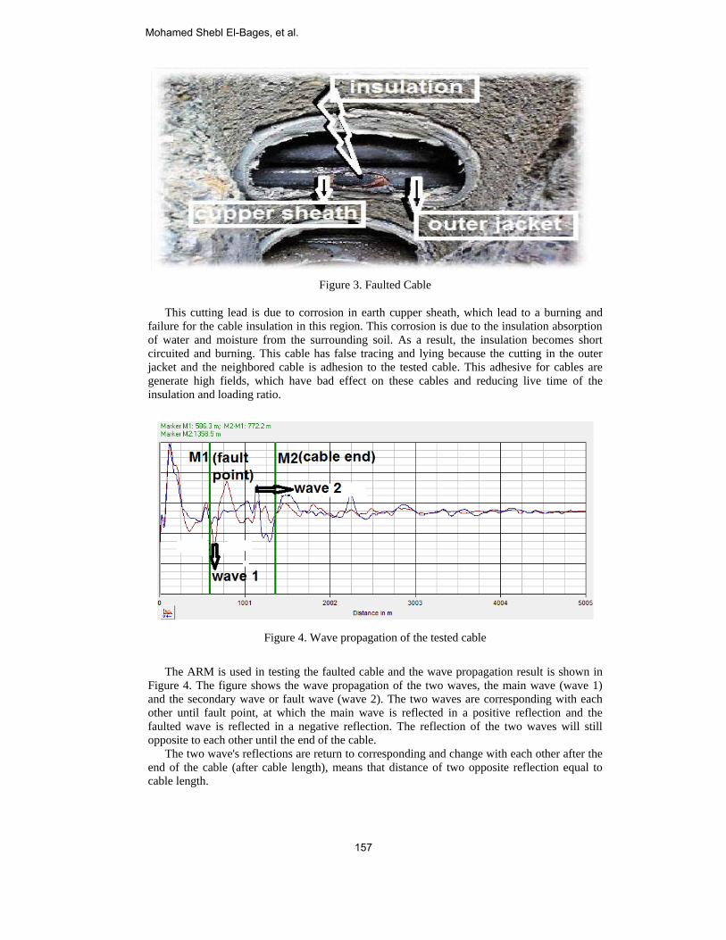
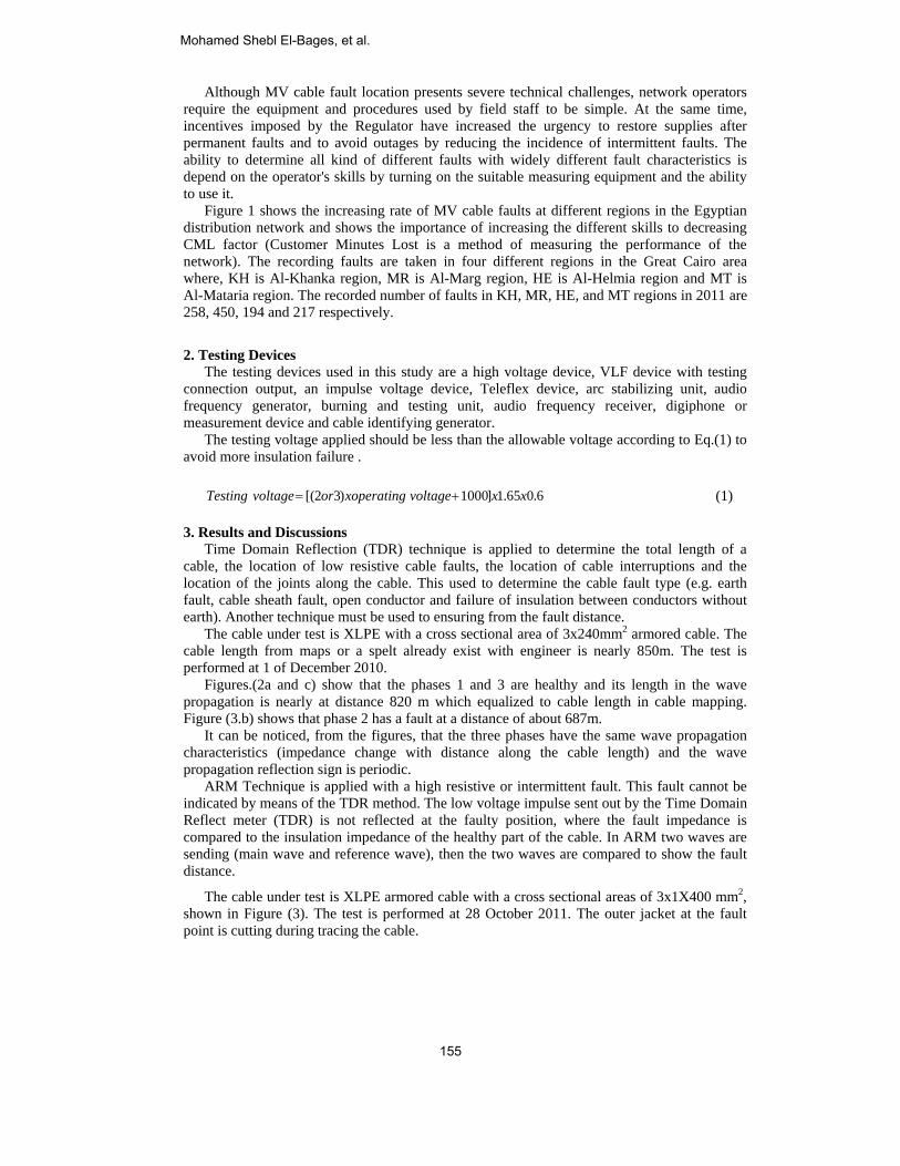
Figure 3. Faulted Cable
This cutting lead is due to corrosion in earth cupper sheath, which lead to a burning and failure for the cable insulation in this region. This corrosion is due to the insulation absorption of water and moisture from the surrounding soil. As a result, the insulation becomes short circuited and burning. This cable has false tracing and lying because the cutting in the outer jacket and the neighbored cable is adhesion to the tested cable. This adhesive for cables are generate high fields, which have bad effect on these cables and reducing live time of the insulation and loading ratio.
Figure 4. Wave propagation of the tested cable
The ARM is used in testing the faulted cable and the wave propagation result is shown in Figure 4. The figure shows the wave propagation of the two waves, the main wave (wave 1) and the secondary wave or fault wave (wave 2). The two waves are corresponding with each other until fault point, at which the main wave is reflected in a positive reflection and the faulted wave is reflected in a negative reflection. The reflection of the two waves will still opposite to each other until the end of the cable. The two wave's reflections are return to corresponding and change with each other after the end of the cable (after cable length), means that distance of two opposite reflection equal to cable length.
Mohamed Shebl El-Bages, et al.
157

The figure shows that the cable length is about 1300m from the cable mapping or a spelt already exist. Also, the length in the wave propagation at the Teleflex screen is 1358m at M2 marker at the cable end. The fault point is at a distance 586 m at M2 marker. Two notes must be taken into considerations: 1- The ARM is used when the cable length is short. 2- Some cases of cable faults does not appear by ARM technique, because these cable are long
or very low fault impedance as shown in Figure 5.
Figure 5. Wave propagation of cable by ARM
As shown in Figure 5, the propagations along the cable length of two waves (main wave and secondary wave) are similar, i.e. this method doesn’t show the characteristic of the fault and the fault distance in pre-location of this cable cannot recognize. Another method as an impulse method or decay method must be used in this case. ICE measurement technique is used to locate high resistive faults and intermittent faults for very long cable, where low voltage impulse of IRG is damped off before reaching the fault point, or before returning again to IRG. The fault distance can be determined by the full period or by the period between the lowest bottoms to the highest top before correct bottom.
Figure 6. Faulted cable photograph before repairing
The cable under test is cutting its component separated from each other (outer jacket, insulation and conductor) which caused explosion in this point, as seen in Figure 6, the cable under test is XLPE cable with a cross sectional area of 3x240 mm2. The cable is tested at 20 Mach 2010.
Long Term Analysis of Cables Problems in Egyptian Distribution Network
158

Figure 7. Wave propagation of faulted cable by using impulse method
Figure 7 shows that the fault distance in one periodic impulse is nearly 4760 m between the two cursers M1 and M2. This cable length from old maps is 9500 m, so the ARM did not used because the cable very long so that used impulse technique to determine the propagation characteristic. Decay measurement Technique is used to locate the high resistive faults and the intermittent faults on chargeable cables which impulse method does not locate it. The reason of these phenomena is that the cable appears as a healthy cable until definite value of applied testing voltage, then the cable insulation will break down after this value, means that the breakdown voltage or the applied voltage is less than the required allowable testing voltage by constant value to ensuring from the cable validity. The cable under test is XLPE cable with a cross sectional area of 3x1x400mm2. The faulted cable, shown in Figure 8, is tested in 28 September 2011. The faulted point of the cable is located at the cable insulation nearby the old joint, where many cables are laying on each other above the ground. This situation has very bad effects on the testing results, lifetime of these cables, and the loading ratio of the cables when operating.
Figure 8. Faulted cable photograph before repairing
Figure 9 shows that the wave propagation is periodic and the fault distance located between cursers M1 and M2 is about 620 m. The breakdown and flash over of this faulty cable is at 9 KV DC, the testing voltage is 18 KV DC and the operating voltage is 11 KV AC. It can be noticed that the cable seams as a healthy cable until 9 KV, at which the cable insulation will breakdown. This testing voltage and breakdown, or flashover, in cable insulation is not permeable in cable testing to ensure from the cable validity in the service.
Mohamed Shebl El-Bages, et al.
159
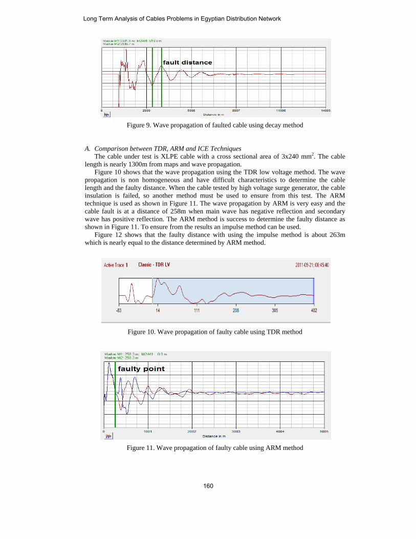
Figure 9. Wave propagation of faulted cable using decay method
A. Comparison between TDR, ARM and ICE Techniques The cable under test is XLPE cable with a cross sectional area of 3x240 mm2. The cable length is nearly 1300m from maps and wave propagation. Figure 10 shows that the wave propagation using the TDR low voltage method. The wave propagation is non homogeneous and have difficult characteristics to determine the cable length and the faulty distance. When the cable tested by high voltage surge generator, the cable insulation is failed, so another method must be used to ensure from this test. The ARM technique is used as shown in Figure 11. The wave propagation by ARM is very easy and the cable fault is at a distance of 258m when main wave has negative reflection and secondary wave has positive reflection. The ARM method is success to determine the faulty distance as shown in Figure 11. To ensure from the results an impulse method can be used. Figure 12 shows that the faulty distance with using the impulse method is about 263m which is nearly equal to the distance determined by ARM method.
Figure 10. Wave propagation of faulty cable using TDR method
Figure 11. Wave propagation of faulty cable using ARM method
Long Term Analysis of Cables Problems in Egyptian Distribution Network
160

Figure 12. Wave propagation of faulty cable using ICE method
B. Pinpointing for Cable Fault The pin pointing technique depend on the types of field generated around the cable, signal sending in the cable and sound heard clearly above the fault point by special microphone. The fields around the cable are electric field and magnetic Field. The magnetic field can be divided into sheath Field, twist Field, high Frequency Field and sound Field. Inductive Method used in Pin Pointing of Cable Fault has two methods, namely the Maximum Method and the Minimum Method. The purposes of using inductive method are the cable route tracing, determination of cable depth, exactly cable fault Pin-Pointing and cable Identification Practical notes can be derived here such as: A. The cables test result and its characteristics depending on the Cable specifications, the
practical applications to different methods by try and notice the wave propagation of the cable and the old knowledge to the network as name of the cable by old maps, a spelt of the cable already existing and practical experience of the tests engineer in this field are necessary to get easy and correct result for the tests operation.
B. For the same cable some methods or all of them are success to determine the wave propagation characteristics.
C. Some cable is disconnected from service as indicated that the cable has a fault. But when the cable is tested, it is observed that the cable is healthy, also some cable has many non-homogeneous points along the cable tracing which are the basic causes for any fault. This cable should be replaced to reduce feeder outages resulting from the high leakage current from the non-homogeneous points and weakness points. This phenomenon occurs frequently in oil-impregnated paper cable, and few numbers in XLPE cables. This phenomenon resulted due to the following reasons: 1. When the temperature of oil-impregnated paper insulation increased, the leakage
current will increased and may reach to the minimum pick-up current, then the cable will be disconnected as faulty cable. After that the oil temperature will decreased and the cable will restore partially its insulation after definite time. Then the cable is seen to be healthy when it tested after disconnection, and this phenomenon is found to be frequently occurring in the Egyptian distribution network.
2. The cable conductor, at any joint, may be melting and separated under operating conditions. After definite time from disconnection the cable, it return to connect again, and it is rarely occur.
Mohamed Shebl El-Bages, et al.
161

3. The fault in any phase may be makes a sufficient gap to insulate the faulty phase due to low explosion, this phenomenon is rarely occurring.
D. The non homogeneous and weakness points occurred from: 1. Bad manufacture (exist cable in Egyptian distribution network with non homogeneous
insulation along the cable is called the American cable specified with red outer jacket, With a great satisfaction that these cables reduce harmonics).
2. Bad loading (over loads, harmonics, equivalent loads for three phases) 3. Bad laying and Non correct path 4. Long age for cable and soil corrosion in cable component 5. Bad testing 6. Presence of many connections in the cable 7. Bad storage and translation 8. Water tree in XLPE cable 9. Bad repairing faults
i. Wrong used for fir when heating ii. No cleaning for cable or moisture iii. Not suitable cross section aria for cable joint terminal iv. Not suitable material for cable joint or terminal v. Not follow standard when making cable joint or terminal vi. Bad connection for cable joint or terminal
4. Conclusions The distribution networks faced great problems as they constructed from many years and there is not any accurate mapping for cables routing. Also, the networks contain different types of cables. The life time of a great number of cables is finished and becomes invalid. The above problems generate a large number of failures in the distribution networks and the rate of rise of these failure increases. This study shows that a great number of failures also happened in the manhole, where a connection of cables is doing. This problem can be referred to technicians' errors in cable jointing. Reference: [1] IR. E. F. Steennis, and P. A. A. Wouters "On line inception detection and localization for
low voltage faults in oil impregnated paper cables" capacities group elektrische energy technique electrical power system, July 2002.
[2] M. S. Naidu and V. Kamaraju, "High Voltage Engineering", Third Edition, February 2002.
[3] Ali Mohamed and Ali Abo Gurain, "Investigation and Analysis of Thermal Aging of XLPE and PVC Cable Insulation Materials Manufactured in Saudi Arabia", MSc thesis, King Fahd University of Petroleum, KSA, June 2003.
[4] Gokcen Bas, "Electric Field Analysis in Stress Controlled High Voltage Cable" first edition, Jan. 2005.
[5] H. Khorashadi Zadeh and M. R. Agobrahimi, "Anoval Approach to Fault Classification and Fault Location for Medium Voltage Cables Based on Artificial Network", International Journal of Computation Intelligence, 2006.
[6] Maroof Pirouti, Amin A.Fatih, Ibrahim B. Sadik "Fault Identification and Classification for Short Medium Voltage Underground Cable Based on Artificial Neural Networks" Journal of Electrical Engineering" Vol. 59, No 5, pp. 272 – 276, 2008.
[7] Tabias neier, "Cable fault location in LV, MV and HV underground cable practical experience", landesgericht feldkirch, April 2009.
[8] Maroof Pirouti, "Neural network based fault localization estimator for short medium voltage underground cables" International Journal of Electrical Power and Power Engineering, 2008.
Long Term Analysis of Cables Problems in Egyptian Distribution Network
162

[9] C. AUsinof EKon
[10] AuthMed
[11] CurtReco
[12] Seba[13] Vive
LimJourIssu
dischargePower Ne
Apisit and A. Nng Discrete WEngineering anng. hors "Practicaldill public regiotis Lanham "Prommended for a KMT Compaek Kumar and
mitations and Drnal of Eemrgie 6, June 2012
MohaUnive1991, ElectrElectrUnive
Mousareceivethe MuniverVoltagprofesat ShoField
e in gas insulatetworks.
M. Z. degree EnginereceiveCurrenat the networkcustom
NgaoupitakkulWavelet Transfo
nd Computer
l Experience aon, 2010. resident BakerElectric Motor
any "Catalog od Deepak RajDrawbacks oning Technolog.
amed Shebl ersity, Cairo, E
and the Ph.Drical Engineerrical Engineerinersity
a A. Abd-Allaed the B.Sc. d.Sc. degree in
rsity, benha brage Engineeringsor with the Elubra, Benha UAssessment
ted systems, E
A. Elhawaryin electrical e
eering at Shoue the M.Sc. dntly, he joined w
Cairo distribuks. Operated i
mer support and
l, "Identificatioorm" ProceediScientists, Vo
and Practical R
r Instrument Cr Predictive Mf Car Test Van
ajouria, "Fault n Practical Apgy and Advanc
El-Bages reEgypt in 1982 aD. degree in ring Currentlyng department
ah was born idegree in elect
High Voltageanch, Cairo, Egg in 1992 frolectrical Engin
University. His and Mitigatio
Electromagnetic
was born in Caengineering wiubra, Benha Udegree in electwith the Cairo dution networksin different deservice in the c
on of Fault Tyngs of The Int
ol. II, IMECS,
Result" North C
ompany" UndeMaintenance, 19n" juryman 201
Detection Tepproach of M
ced Engineerin
eceived the Band M.Sc. degr1997 from Ca
y. He is an at, Faculty of En
in Cairo, Egyptrical Engineere Engineering gypt. He receivom Cairo Unneering departm
research activon around Ec Compatibilit
airo, Egypt, onith honor degr
University, Caitrical engineerdistribution coms and now wiepartment and company.
ypes For Undeternational Mu March 17-19
Cairo Distribut
erstanding the960. 10. echnique by U
Measurements"ng, ISSN 2250
B.Sc. degree ree from Benhaairo universityassistant profengineering at S
pt, on August ring with honoin 1988, both
ved the Ph.D. dniversity. He ment, Faculty ovity includes ElElectrical Equty, Transient P
n 1984. He receree in 2007 frro, Egypt. In ring from the mpany in 2008 ith South Delt
is now respo
erground Cableulti-conference9, 2010, Hong
tion Company,
e Tests that are
Using OTDR: International
0-2459, Vol. 2,
from Benhaa University in
y, all in Poweressor with theShoubra, Benha
16, 1961. Heor in 1984 and
from Zagazigdegree in Highis currently aof Engineeringlectromagnetic
uipments, GasPhenomenon in
eived the B.Scrom Faculty of
2012, he willsame faculty.as engineering
ta Distributiononsible for the
e e g
,
e
: l ,
a n r e a
e d g h a g c s n
. f l . g n e
Mohamed Shebl El-Bages, et al.
163