logix5000 control systems: connect ... - rockwell...
TRANSCRIPT
Logix5000 Control Systems: Connect ArmorBlock I/O Modules over an Ethernet NetworkLogix5000 Controllers, 1732E ArmorBlock I/O Modules
Quick Start
Important User InformationRead this document and the documents listed in the additional resources section about installation, configuration, and operation of this equipment before you install, configure, operate, or maintain this product. Users are required to familiarize themselves with installation and wiring instructions in addition to requirements of all applicable codes, laws, and standards.
Activities including installation, adjustments, putting into service, use, assembly, disassembly, and maintenance are required to be carried out by suitably trained personnel in accordance with applicable code of practice.
If this equipment is used in a manner not specified by the manufacturer, the protection provided by the equipment may be impaired.
In no event will Rockwell Automation, Inc. be responsible or liable for indirect or consequential damages resulting from the use or application of this equipment.
The examples and diagrams in this manual are included solely for illustrative purposes. Because of the many variables and requirements associated with any particular installation, Rockwell Automation, Inc. cannot assume responsibility or liability for actual use based on the examples and diagrams.
No patent liability is assumed by Rockwell Automation, Inc. with respect to use of information, circuits, equipment, or software described in this manual.
Reproduction of the contents of this manual, in whole or in part, without written permission of Rockwell Automation, Inc., is prohibited.
Throughout this manual, when necessary, we use notes to make you aware of safety considerations.
Labels may also be on or inside the equipment to provide specific precautions.
Allen-Bradley, Rockwell Software, Rockwell Automation, Logix5000, RSLogix 5000, RSLinx, ControlLogix, Studio 5000, Studio 5000 Logix Designer and ArmorBlock are trademarks of Rockwell Automation, Inc.
Trademarks not belonging to Rockwell Automation are property of their respective companies.
WARNING: Identifies information about practices or circumstances that can cause an explosion in a hazardous environment,
which may lead to personal injury or death, property damage, or economic loss.
ATTENTION: Identifies information about practices or circumstances that can lead to personal injury or death, property
damage, or economic loss. Attentions help you identify a hazard, avoid a hazard, and recognize the consequence.
IMPORTANT Identifies information that is critical for successful application and understanding of the product.
SHOCK HAZARD: Labels may be on or inside the equipment, for example, a drive or motor, to alert people that dangerous
voltage may be present.
BURN HAZARD: Labels may be on or inside the equipment, for example, a drive or motor, to alert people that surfaces may
reach dangerous temperatures.
ARC FLASH HAZARD: Labels may be on or inside the equipment, for example, a motor control center, to alert people to
potential Arc Flash. Arc Flash will cause severe injury or death. Wear proper Personal Protective Equipment (PPE). Follow ALL
Regulatory requirements for safe work practices and for Personal Protective Equipment (PPE).
Where to Start
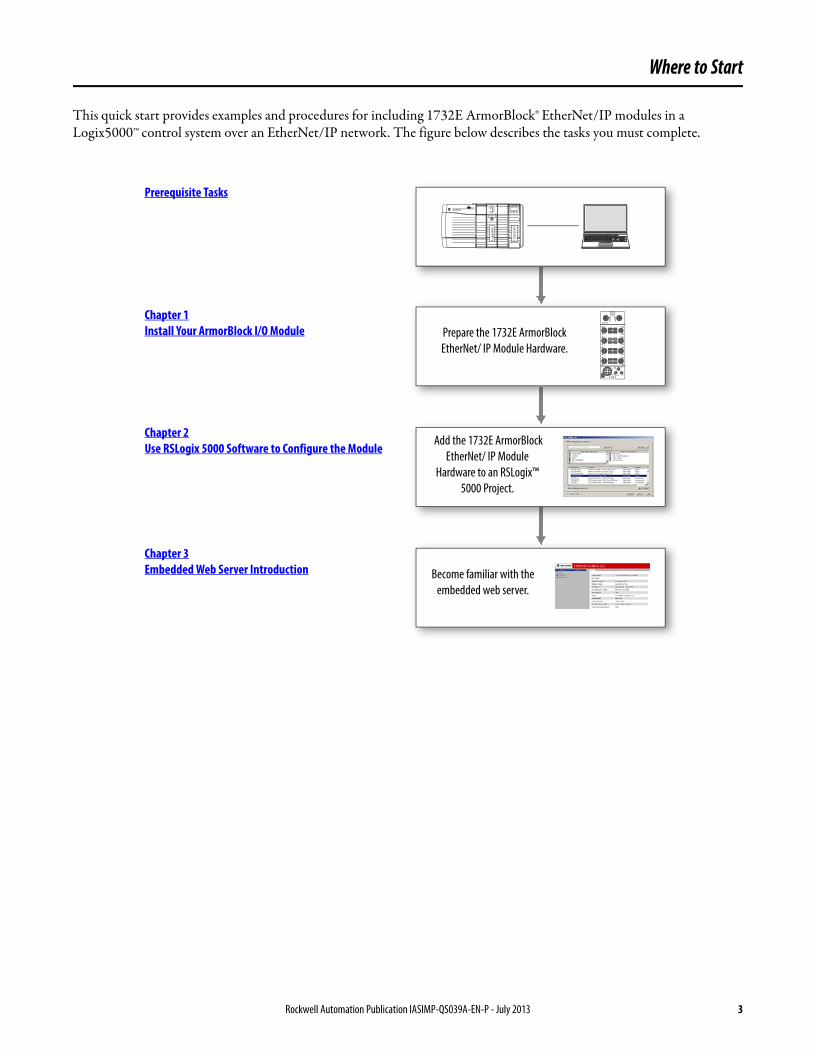
This quick start provides examples and procedures for including 1732E ArmorBlock® EtherNet/IP modules in a Logix5000™ control system over an EtherNet/IP network. The figure below describes the tasks you must complete.
RUN REM PROG
OK
RS232
I/O
BAT
RUN
Logix5565
1756
-EN
2T
EtherNet/IP
Logi
x556
5
LINK 1
MOD
7
65
4
3
2
1
0
PWR
X100 X1
X10
8
910
11
12
13
14
15
NET
LINK 2Chapter 1Install Your ArmorBlock I/O Module
Prerequisite Tasks
Prepare the 1732E ArmorBlock
EtherNet/ IP Module Hardware.
Add the 1732E ArmorBlock
EtherNet/ IP Module
Hardware to an RSLogix™
5000 Project.
Chapter 2Use RSLogix 5000 Software to Configure the Module
Chapter 3Embedded Web Server Introduction Become familiar with the
embedded web server.
Rockwell Automation Publication IASIMP-QS039A-EN-P - July 2013 3
Where to Start
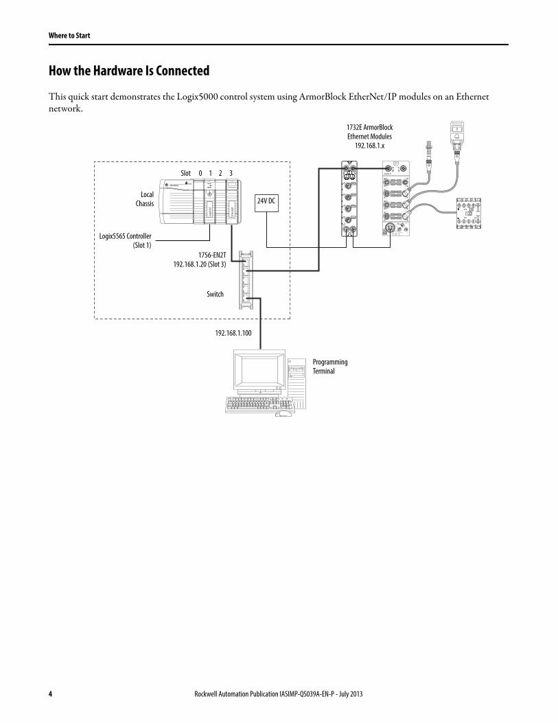
How the Hardware Is Connected
This quick start demonstrates the Logix5000 control system using ArmorBlock EtherNet/IP modules on an Ethernet network.
RUN REM PROG
OK
RS232
I/O
BAT
RUN
Logix5565
1756
-EN
2T
EtherNet/IP
Logi
x556
5
LINK 1
MOD
7
6
5
4
3
2
1
0
PWR
X100 X1
X10
8
9
10
11
12
13
14
15
NET
LINK 2
Switch
192.168.1.100
1732E ArmorBlock Ethernet Modules
192.168.1.x
1756-EN2T192.168.1.20 (Slot 3)
LocalChassis
Programming Terminal
Logix5565 Controller(Slot 1)
Slot 0 1 2 3
24V DC
4 Rockwell Automation Publication IASIMP-QS039A-EN-P - July 2013

Table of Contents
Preface About This Publication. . . . . . . . . . . . . . . . . . . . . . . . . . . . . . . . . . . . . . . . . . . . . 7Prerequisite Tasks . . . . . . . . . . . . . . . . . . . . . . . . . . . . . . . . . . . . . . . . . . . . . . . . . . 7Other Logix5000 Control System Quick Starts . . . . . . . . . . . . . . . . . . . . . . . 7Required Software . . . . . . . . . . . . . . . . . . . . . . . . . . . . . . . . . . . . . . . . . . . . . . . . . 8Parts List . . . . . . . . . . . . . . . . . . . . . . . . . . . . . . . . . . . . . . . . . . . . . . . . . . . . . . . . . . 8Additional Resources . . . . . . . . . . . . . . . . . . . . . . . . . . . . . . . . . . . . . . . . . . . . . . . 8
Chapter 1Install Your ArmorBlock I/O Module
Before You Begin . . . . . . . . . . . . . . . . . . . . . . . . . . . . . . . . . . . . . . . . . . . . . . . . . . 9What You Need . . . . . . . . . . . . . . . . . . . . . . . . . . . . . . . . . . . . . . . . . . . . . . . . . . . 9Follow These Steps . . . . . . . . . . . . . . . . . . . . . . . . . . . . . . . . . . . . . . . . . . . . . . . . . 9Mount the Module . . . . . . . . . . . . . . . . . . . . . . . . . . . . . . . . . . . . . . . . . . . . . . . 10Wire the Module. . . . . . . . . . . . . . . . . . . . . . . . . . . . . . . . . . . . . . . . . . . . . . . . . 11Set the Network Address . . . . . . . . . . . . . . . . . . . . . . . . . . . . . . . . . . . . . . . . . 12
Chapter 2Use RSLogix 5000 Software to Configure the Module
Before You Begin . . . . . . . . . . . . . . . . . . . . . . . . . . . . . . . . . . . . . . . . . . . . . . . . 15What You Need . . . . . . . . . . . . . . . . . . . . . . . . . . . . . . . . . . . . . . . . . . . . . . . . . 15Follow These Steps . . . . . . . . . . . . . . . . . . . . . . . . . . . . . . . . . . . . . . . . . . . . . . . 15Adding the Local EtherNet I/P Bridge to the I/O Configuration. . . . . 16Configure the Bridge Module . . . . . . . . . . . . . . . . . . . . . . . . . . . . . . . . . . . . . 18Add Ladder Logic to Test the Lights on the 1732E-OB16MR Module 19Download the Project to Your Logix5000 Controller . . . . . . . . . . . . . . . 23Test the 1732E-OB16M12R Output Module’s Light . . . . . . . . . . . . . . . 24
Chapter 3Embedded Web Server Introduction
Before You Begin . . . . . . . . . . . . . . . . . . . . . . . . . . . . . . . . . . . . . . . . . . . . . . . . 25What You Need . . . . . . . . . . . . . . . . . . . . . . . . . . . . . . . . . . . . . . . . . . . . . . . . . 25Follow These Steps . . . . . . . . . . . . . . . . . . . . . . . . . . . . . . . . . . . . . . . . . . . . . . . 25Access the Home Page of the Web Server . . . . . . . . . . . . . . . . . . . . . . . . . . 26Log On to the Web Server . . . . . . . . . . . . . . . . . . . . . . . . . . . . . . . . . . . . . . . . 26Navigating the Web Server Pages . . . . . . . . . . . . . . . . . . . . . . . . . . . . . . . . . . 27
Rockwell Automation Publication IASIMP-QS039A-EN-P - July 2013 5

Table of Contents
Notes:
6 Rockwell Automation Publication IASIMP-QS039A-EN-P - July 2013

Preface
About This PublicationThis quick start provides examples and procedures for including 1732E ArmorBlock EtherNet/IP modules in a Logix5000 control system over an EtherNet/IP network (star topology configuration). This document does not describe how to use the I/O modules in a device-level ring (DLR) or linear topology. For information on using modules in a DLR or linear topology, see the EtherNet/IP Embedded Switch Technology Application Guide, publication ENET-AP005.
The programming examples included are not complex, and offer easy solutions to verify that devices are functioning and communicating properly.
The beginning of each chapter contains the following information. Read these sections carefully before beginning work in each chapter:
• Before You Begin – This section lists the steps that must be completed and decisions that must be made before starting that chapter.
• What You Need – This section lists the tools that are required to complete the steps in the current chapter. This includes, but is not limited to, hardware and software.
• Follow These Steps – This illustrates the steps in the current chapter and identifies which steps are required to complete the examples using specific networks.
Prerequisite TasksSeveral tasks must be performed as a prerequisite before proceeding. For example, before you can add 1732E ArmorBlock EtherNet/IP modules to an RSLogix 5000 project, you must create the project. Perform the following before proceeding.
1. Prepare the Logix5000 control system hardware by assembling the components and connecting it to the Ethernet network.This quick start uses a ControlLogix® chassis containing the Logix 5565 processor in slot 1 and a 1756-EN2T bridge module in slot 3. The 1732E ArmorBlock module is mounted remotely as shown on page 4. If you use a different Logix5000 controller and Ethernet module, you can complete the tasks in these chapters, but you must account for any hardware differences.
2. Prepare the computer by installing any required software, for example RSLogix 5000 software.
3. Configure the networks by setting the IP address, subnet mask, and optional Gateway address. Use the Rockwell BOOTP/DHCP utility, version 2.3 or later, that ships with RSLogix 5000 or RSLinx® software. You can also use this utility to reconfigure a device whose IP address must be changed.
4. Create an RSLogix 5000 project that includes all required control system components.
5. Your project must include the Ethernet module used by your controller to access the Ethernet network.
Other Logix5000 Control System Quick StartsThis quick start describes how to use a single component-type over a single network in a Logix5000 control system. Typically, a Logix5000 control system includes more than the controller, communication module and a single component over a single network. For example, the system can have remote I/O modules, HMI devices and drives in addition to the controller and communication modules. For a complete list of Logix5000 control system quick starts that describe how to use other devices in Logix5000 control systems, see the Integrated Architecture: Logix5000 Control Systems Quick Starts Quick Reference, publication IASIMP-QR024.
Rockwell Automation Publication IASIMP-QS039A-EN-P - July 2013 7

Preface
Required SoftwareThe module and the applications described in this publication are compatible with the following firmware revisions and software versions.
Parts ListThe following components are required to complete the tasks described in this publication.
Additional ResourcesThese documents contain additional information concerning related products from Rockwell Automation.
You can view or download publications at http:/www.rockwellautomation.com/literature/. To order paper copies of technical documentation, contact your local Allen-Bradley distributor or Rockwell Automation sales representative.
Product Firmware Revision / Software Version
1756-EN2T, 1756-EN2TR, 1756-EN3TR 3.000 revision when using RSLogix 5000 version 20 or Studio 5000 Logix Designer™ version 21 or later
RSLogix 5000 software 20.00.00 or later
RSLinx software 2.56.00 or later
BOOTP/DHCP utility Version automatically installed with RSLogix 5000 software or Studio 5000™ environment and varies according to that software’s version.
Description Catalog No Quantity
Logix 5565 controller 1756-L65 1
Ethernet I/P module 1756-EN2T 1
1732E ArmorBlock EtherNet/IP module 1732E-OB16M12R 1
Resource Description
1732E EtherNet/IP ArmorBlock supporting Sequence of Events User manual, publication 1732E-UM002
Provides a detailed description of how to install, configure, and use your 1732E-IB16M12SOEDR module.
1732E ArmorBlock 2 Port Ethernet Module Installation Instructions, publication 1732E-IN004
Provides information on installing the ArmorBlock 2-port EtherNet/IP module.
1732E EtherNet/IP Dual Port 8-Point Digital Modules Installation Instructions, publication 1732E-IN007
Describes how to install your 1732E Dual-port 8-point Digital Module.
1732E ArmorBlock Dual-Port EtherNet/IP 4-Point Thermocouple and RTD Input, publication 1732E-IN005
Describes how to install your 1732E ArmorBlock Dual-port EtherNet/IP 4-point Thermocouple and RTD Input Module.
1732E ArmorBlock Dual-Port EtherNet/IP 4-Point Analog Input/Output User Manual, publication 1732E-UM005
Describes how to install, configure, and troubleshoot your 1732E Dual-port EtherNet/IP 4-point Analog Input and Output Modules.
1732E ArmorBlock Dual-Port EtherNet/IP 4-Point Thermocouple and RTD User Manual, publication 1732E-UM004
Provides a detailed description of module functionality, configuration, installation and information on how to use the ArmorBlock Dual-port EtherNet/IP 4-point Thermocouple and RTD modules.
Logix5000 Controllers Common Procedures Programming Manual, publication 1756-PM001
Provides details about adding and configuring modules, establishing communication, and writing ladder logic.
Industrial Automation Wiring and Grounding Guidelines, publication 1770-4.1. Provides general guidelines for installing a Rockwell Automation industrial system.
Product Certifications website, http://www.ab.com Provides declarations of conformity, certificates, and other certification details.
8 Rockwell Automation Publication IASIMP-QS039A-EN-P - July 2013

Chapter 1
Install Your ArmorBlock I/O Module
This chapter shows you how to install and wire the 1732E ArmorBlock EtherNet/IP module.
Before You Begin
Perform the prerequisite tasks outlined on page 7.
What You Need
The only tools required are a flat or Phillips-head screwdriver and a drill.
Follow These Steps
Complete these steps to install your ArmorBlock EtherNet/IP module.
Mount and connect the
1732E I/O module
on page 10
Configure the model on the
Ethernet network
on page 12
Wire the auxiliary power
and connect the Ethernet
cable on page 11
Start
Rockwell Automation Publication IASIMP-QS039A-EN-P - July 2013 9

Chapter 1
Mount the Module
Two holes are used to mount the module directly to a panel or machine. Mounting holes accommodate #6 (M3) pan-head screws. The torque specification is 0.68 N•m (6 lb•in).
To mount the module on a wall or panel, use the screw holes provided in the module. Refer to the drilling dimensions illustration to guide you in mounting the module.
Mounting Dimensions
Install the mounting base as follows.
1. Lay out the required points as shown.
2. Drill the necessary holes for #6 (M3) pan-head screws.
3. Mount the module by using #6 (M3) screws.
High Vibration Area Mounting
If you mount the module in an area that is subject to shock or vibration, we recommend that you use a flat washer and lock washer as shown. Torque the mounting screws to 0.68 N•m (6 lb•in).
LINK 1
MOD
7
65
4
3
2
1
0
PWR
X100 X1
X10
8
910
11
12
13
14
15
NET
LINK 2
65.0(2.56)
179.0(7.05)
169.0(6.65)
26.5(1.04)
43.3(1.70)
Dimensions are in millimeters (inches)
Lock Washer
Flat Washer
10 Rockwell Automation Publication IASIMP-QS039A-EN-P - July 2013

Chapter 1
Wire the Module
Connect the I/O, network and auxiliary cables to the module. The ArmorBlock EtherNet/IP family has 5-pin micro-style connectors. Caps are provided to cover the unused connectors on your module. Connect the quick-disconnect cord sets you selected for your module to the appropriate ports.
Functional Earth
This screw grounds the I/O block EtherNet/IP communication circuitry that is designed to reduce the effect of noise on the network. The circuitry requires a solid earth-ground connection, either through a metal screw to a grounded metal panel or through a wire.
I/O Connectors
Micro-style 5-pin Input Female Connector
Micro-style 5-pin Output Female Connector
Self-configuring Connector and Circuitry
D-code Micro Network Female Connector (EtherNet/IP)
LINK 1
MOD NET
LINK 2
Functional Earth
1 2
5
4 3
2
1
345
Common
NC
NO
Ground
802B Limit Switch
(View into connector)Pin 1 Sensor source voltagePin 2 Input BPin 3 ReturnPin 4 Input APin 5 PE
2
1
A1
A2345
Bulletin 100-K Contactor
(View into connector)Pin 1 Not usedPin 2 Output BPin 3 ReturnPin 4 Output APin 5 PE
1 2
5
4 3
(View into connector)Pin 1 Sensor source voltagePin 2 Input or output BPin 3 ReturnPin 4 Input or output APin 5 PE
Output scan list
Input scan listto PLC
from PLC
Input (or output) is on
Turn output onOutput circuit
Input circuit
Connector pin
Sensor or actuator
1 2
5
4 3
4
2
3 1
5
(View into connector)Pin 1 M12_Tx+Pin 2 M12_Rx+Pin 3 M12_Tx-Pin 4 M12_Rx-Pin 5 Connector shell shield FE
Rockwell Automation Publication IASIMP-QS039A-EN-P - July 2013 11

Chapter 1
Mini-style 4-pin Input Male Receptacle (Auxiliary Power)
Set the Network Address
The module ships with the rotary switches set to 999 and DHCP enabled.
To change the network address, you can do one of the following:• adjust the switch on the front of the module.• use a Dynamic Host Configuration Protocol (DHCP) server, such as Rockwell Automation BOOTP/DHCP.• retrieve the IP address from nonvolatile memory.
The I/O block reads the switches first to determine if the switches are set to a valid number. To set the network address:
1. Rotate the three switches on the front of the module by using a small blade screwdriver.
2. Line up the small notch on the switch with the number setting you wish to use.
Valid settings range from 001…254.
The example below shows a default node address set at 163.
3. Cycle power.
When the switches are set to a valid number, the IP address is 192.168.1.xxx (where xxx represents the number set on the switches). The subnet mask is 255.255.255.0 and the gateway address is set to 0.0.0.0. When the module uses the network address set on the switches, it does not have a host name assigned to it or use any Domain Name Server.
If the switches are set to an invalid number (for example, 000 or a value greater than 254 excluding 888), the module checks to see if DHCP is enabled. If DHCP is enabled, the module asks for an address from a DHCP server. The DHCP server also assigns other Transport Control Protocol (TCP) parameters.
If DHCP is not enabled, the IP address (along with other TCP configurable parameters) stored in nonvolatile memory is used.
4 2
3 1
(View into receptacle)Pin 1 Output power +Pin 2 Sensor /MDL power+Pin 3 Sensor/MDL power-Pin 4 Output power-
12 Rockwell Automation Publication IASIMP-QS039A-EN-P - July 2013
Chapter 1
Use the Rockwell Automation BOOTP/DHCP Utility
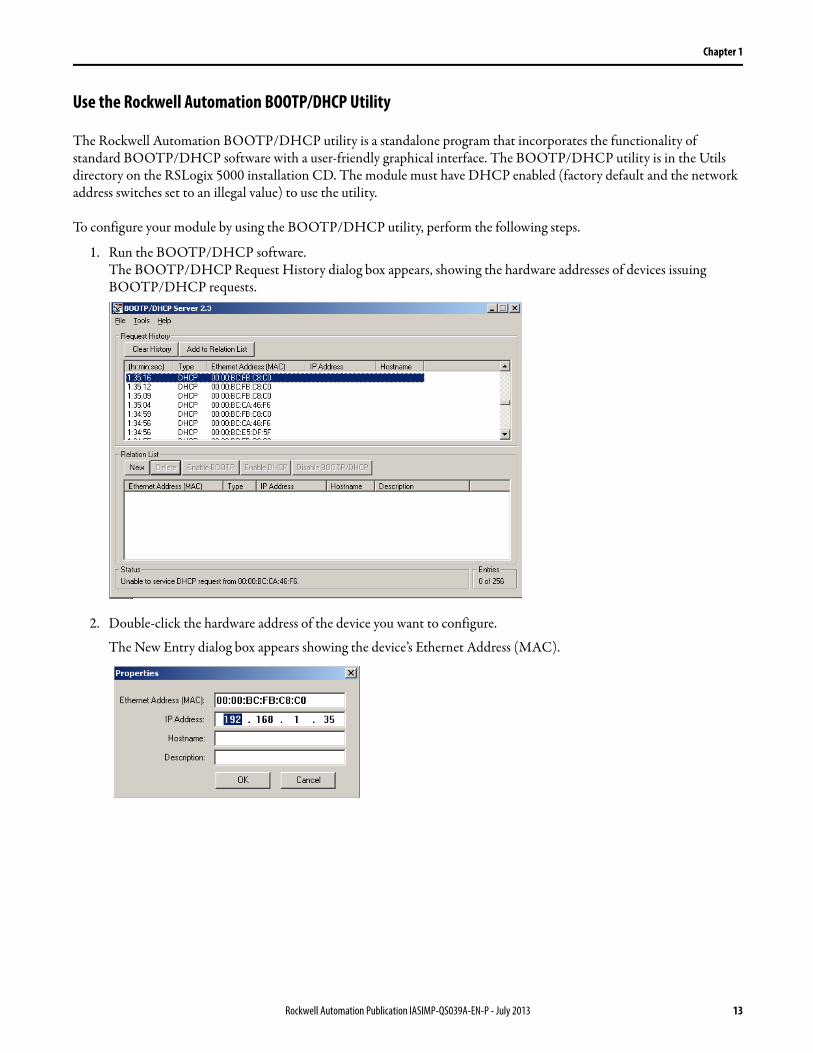
The Rockwell Automation BOOTP/DHCP utility is a standalone program that incorporates the functionality of standard BOOTP/DHCP software with a user-friendly graphical interface. The BOOTP/DHCP utility is in the Utils directory on the RSLogix 5000 installation CD. The module must have DHCP enabled (factory default and the network address switches set to an illegal value) to use the utility.
To configure your module by using the BOOTP/DHCP utility, perform the following steps.
1. Run the BOOTP/DHCP software.The BOOTP/DHCP Request History dialog box appears, showing the hardware addresses of devices issuing BOOTP/DHCP requests.
2. Double-click the hardware address of the device you want to configure.
The New Entry dialog box appears showing the device’s Ethernet Address (MAC).
Rockwell Automation Publication IASIMP-QS039A-EN-P - July 2013 13
Chapter 1
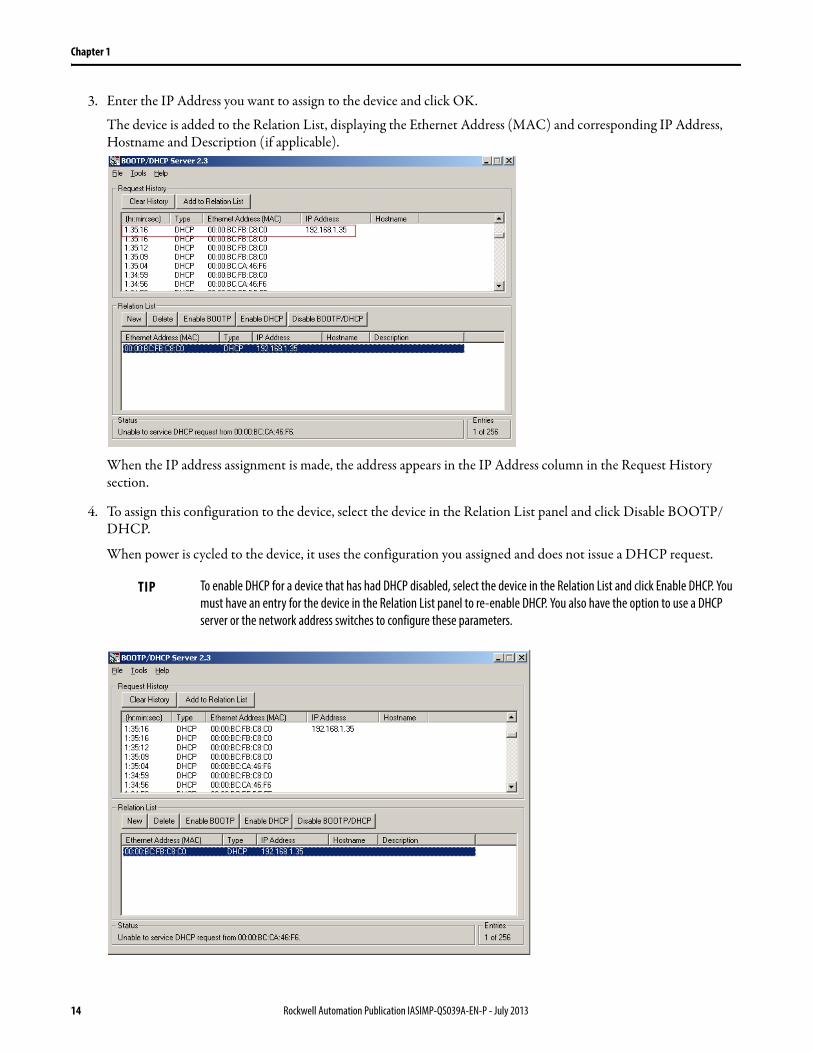
3. Enter the IP Address you want to assign to the device and click OK.
The device is added to the Relation List, displaying the Ethernet Address (MAC) and corresponding IP Address, Hostname and Description (if applicable).
When the IP address assignment is made, the address appears in the IP Address column in the Request History section.
4. To assign this configuration to the device, select the device in the Relation List panel and click Disable BOOTP/DHCP.
When power is cycled to the device, it uses the configuration you assigned and does not issue a DHCP request.
TIP To enable DHCP for a device that has had DHCP disabled, select the device in the Relation List and click Enable DHCP. You
must have an entry for the device in the Relation List panel to re-enable DHCP. You also have the option to use a DHCP
server or the network address switches to configure these parameters.
14 Rockwell Automation Publication IASIMP-QS039A-EN-P - July 2013
Chapter 2
Use RSLogix 5000 Software to Configure the Module
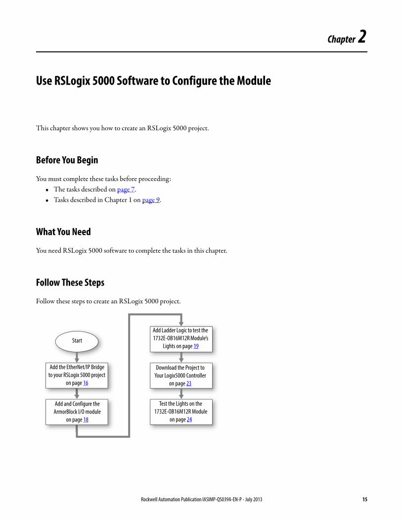
This chapter shows you how to create an RSLogix 5000 project.
Before You Begin
You must complete these tasks before proceeding:• The tasks described on page 7.• Tasks described in Chapter 1 on page 9.
What You Need
You need RSLogix 5000 software to complete the tasks in this chapter.
Follow These Steps
Follow these steps to create an RSLogix 5000 project.
Add the EtherNet/IP Bridge
to your RSLogix 5000 project
on page 16
Add Ladder Logic to test the
1732E-OB16M12R Module’s
Lights on page 19
Add and Configure the
ArmorBlock I/O module
on page 18
Start
Download the Project to
Your Logix5000 Controller
on page 23
Test the Lights on the
1732E-OB16M12R Module
on page 24
Rockwell Automation Publication IASIMP-QS039A-EN-P - July 2013 15
Chapter 2
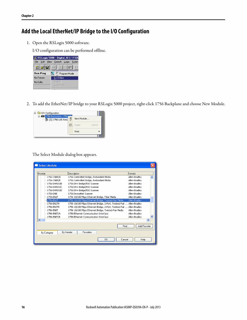
Add the Local EtherNet/IP Bridge to the I/O Configuration
1. Open the RSLogix 5000 software.
I/O configuration can be performed offline.
2. To add the EtherNet/IP bridge to your RSLogix 5000 project, right-click 1756 Backplane and choose New Module.
The Select Module dialog box appears.
16 Rockwell Automation Publication IASIMP-QS039A-EN-P - July 2013
Chapter 2
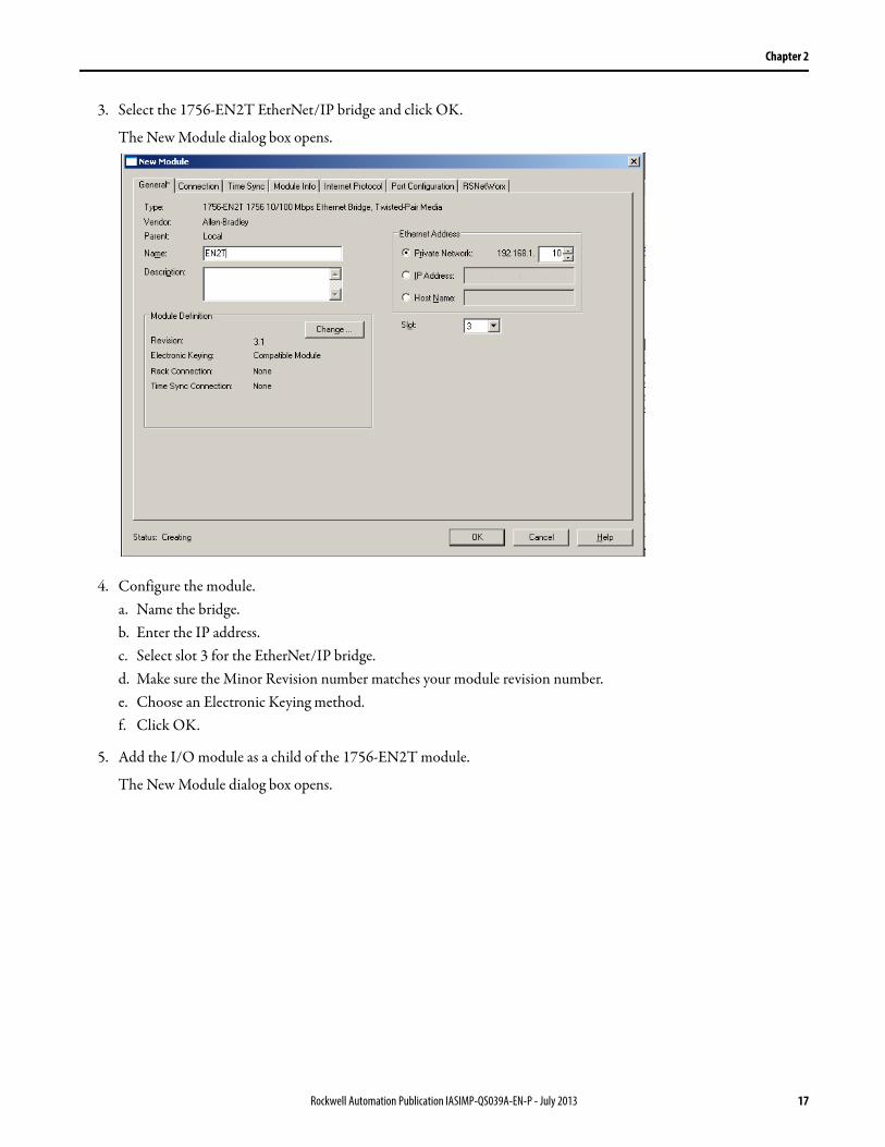
3. Select the 1756-EN2T EtherNet/IP bridge and click OK.
The New Module dialog box opens.
4. Configure the module.a. Name the bridge.b. Enter the IP address.c. Select slot 3 for the EtherNet/IP bridge.d. Make sure the Minor Revision number matches your module revision number.e. Choose an Electronic Keying method. f. Click OK.
5. Add the I/O module as a child of the 1756-EN2T module.
The New Module dialog box opens.
Rockwell Automation Publication IASIMP-QS039A-EN-P - July 2013 17

Chapter 2
Configure the Bridge Module
1. From the Select Module Type dialog box, select the 1732E-OB16M12R module and click Create.
To look for the 1732E-OB16M12R module in the list, you can type the catalog number in the search box or use the filters.
The New Module dialog box appears.
18 Rockwell Automation Publication IASIMP-QS039A-EN-P - July 2013

Chapter 2
2. Enter the Module Properties information as shown.
3. Click OK.
Add Ladder Logic to Test the Lights on the 1732E-OB16MR Module
1. In the controller organizer of the RSLogix 5000 software, expand to show: Tasks > MainTask > MainProgram.
2. Double-click MainRoutine.
A blank routine opens.
3. Add a new rung to the routine.
Rockwell Automation Publication IASIMP-QS039A-EN-P - July 2013 19

Chapter 2
4. From the Element Toolbar, drag and drop an Examine On element and an Output Energize element onto the rung.
5. Double-click ? in the Examine On element.
6. Type “PB” for button.
7. Press Enter.
8. Right-click PB and choose New “PB”.
The New Tag dialog box appears.
20 Rockwell Automation Publication IASIMP-QS039A-EN-P - July 2013
Chapter 2
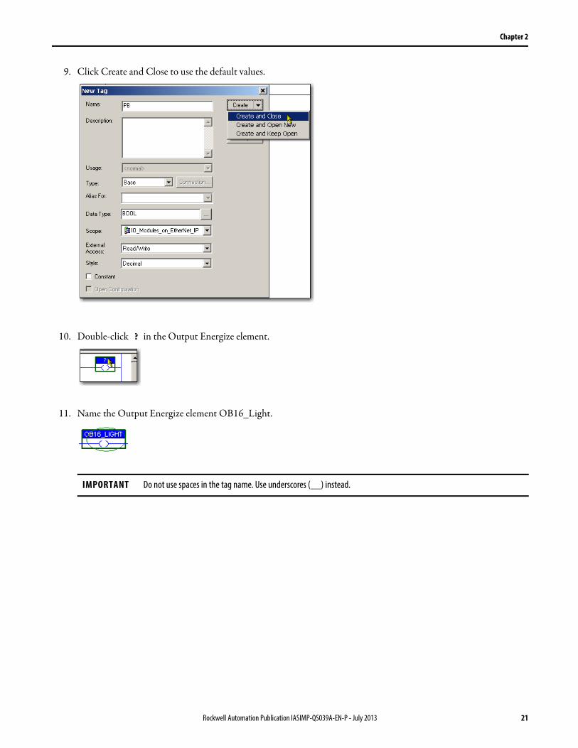
9. Click Create and Close to use the default values.
10. Double-click ? in the Output Energize element.
11. Name the Output Energize element OB16_Light.
IMPORTANT Do not use spaces in the tag name. Use underscores (__) instead.
Rockwell Automation Publication IASIMP-QS039A-EN-P - July 2013 21
Chapter 2
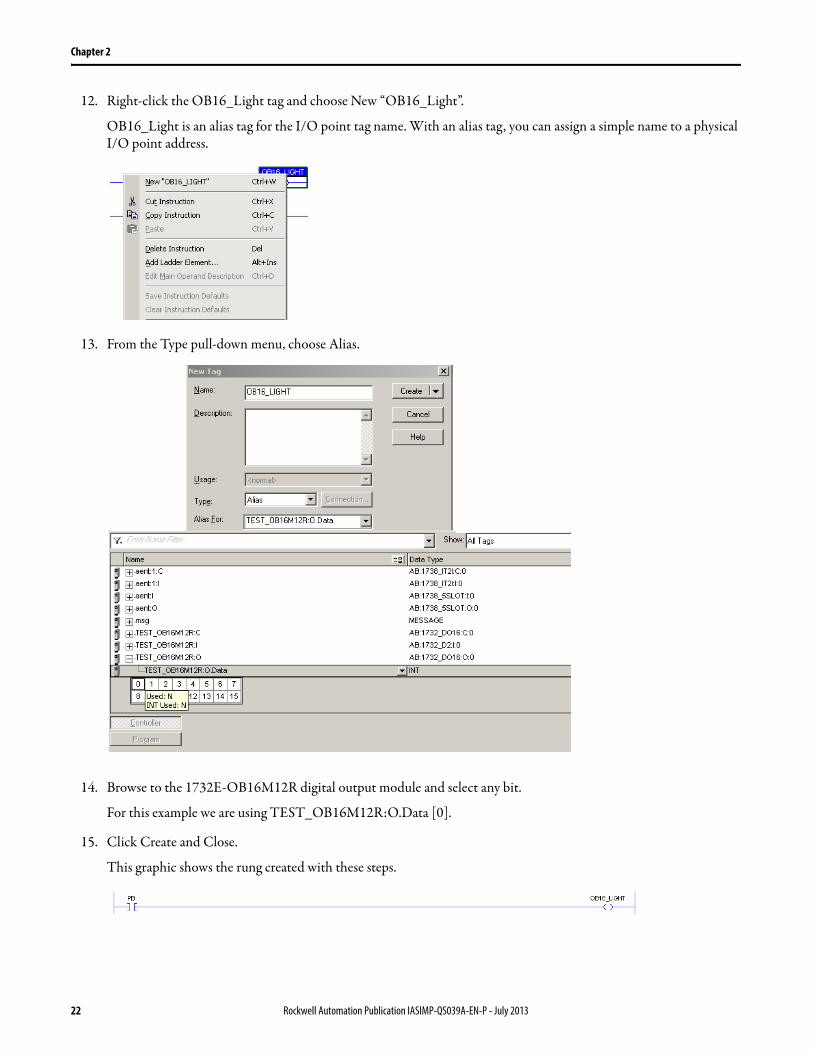
12. Right-click the OB16_Light tag and choose New “OB16_Light”.
OB16_Light is an alias tag for the I/O point tag name. With an alias tag, you can assign a simple name to a physical I/O point address.
13. From the Type pull-down menu, choose Alias.
14. Browse to the 1732E-OB16M12R digital output module and select any bit.
For this example we are using TEST_OB16M12R:O.Data [0].
15. Click Create and Close.
This graphic shows the rung created with these steps.
22 Rockwell Automation Publication IASIMP-QS039A-EN-P - July 2013

Chapter 2
Download the Project to Your Logix5000 Controller
After you configure your module, download it to the owner-controller. The download transfers the entire program to the controller, overwriting any existing program.
1. Save your changes.
2. Move the controller’s switch to Program.
3. Click the Controller Status icon and choose Download.
The Download dialog box appears.
4. Click Download.
This completes the download process.
RUN
REM
PROG
Rockwell Automation Publication IASIMP-QS039A-EN-P - July 2013 23

Chapter 2
Test the 1732E-OB16M12R Output Module’s Light
1. Move the controller’s mode switch to the RUN position.
2. Open the Main Routine of the project to find the ladder logic written earlier.
3. Select the PB and press Ctrl+T.
This toggles the state from 0 to 1 (off to on).
4. Verify that the light on the distributed output module turns on.
5. Press Ctrl+T to toggle the state 1 back to 0 (off ).
6. Choose Go Offline.
24 Rockwell Automation Publication IASIMP-QS039A-EN-P - July 2013

Chapter 3
Embedded Web Server Introduction
Rockwell Automation offers enhanced 1732E ArmorBlock for your EtherNet/IP control systems so you can monitor data remotely via web pages. This chapter shows how you can use the web server.
The module provides access to internal and network diagnostics. This access opens up different, remote access applications to control systems. Use the ArmorBlock I/O web browser to remotely access module data. Use a web browser to monitor live module data and access diagnostic information.
Before You BeginComplete the tasks outlined in previous chapters.
What You NeedYou can access the 1732E ArmorBlock I/O web pages only with Internet Explorer 6.0 or higher. To access data view pages, the browser requires Javascript support. The supported display size is 640 x 480 or greater. Smaller display sizes are acceptable, but could require extensive scrolling to view the information.
Follow These StepsFollow these steps to access the web server.
Access the Home Page of
the Module on page 26
Navigating the Web Server
Pages on page 27
Log On to the Web Server
on page 26
Start
Rockwell Automation Publication IASIMP-QS039A-EN-P - July 2013 25

Chapter 3
Access the Home Page of the Web Server
From your web browser, enter the IP address of the 1732E ArmorBlock module in the Address field and press Enter.
The home page of the module is displayed.
Log On to the Web Server
Many of the features of the 1732E ArmorBlock I/O require you to log on with appropriate access. If you select a feature, such as Configuration, the module prompts you to enter your user name and password.
Default AccessUser Name: administratorPassword: <blank>
26 Rockwell Automation Publication IASIMP-QS039A-EN-P - July 2013

Chapter 3
Navigating the Web Server Pages
You navigate the web server pages by using the navigation panel on the left of the screen. You can also use the tabs across the top to navigate the sections within folders.
Diagnostic Information
Network Settings Information
Rockwell Automation Publication IASIMP-QS039A-EN-P - July 2013 27

Chapter 3
Notes:
28 Rockwell Automation Publication IASIMP-QS039A-EN-P - July 2013

Publication IASIMP-QS039A-EN-P - July 2013Copyright © 2013 Rockwell Automation, Inc. All rights reserved. Printed in the U.S.A.
Rockwell Automation Support
Rockwell Automation provides technical information on the Web to assist you in using its products.At http://www.rockwellautomation.com/support you can find technical and application notes, sample code, and links to software service packs. You can also visit our Support Center at https://rockwellautomation.custhelp.com/ for software updates, support chats and forums, technical information, FAQs, and to sign up for product notification updates.
In addition, we offer multiple support programs for installation, configuration, and troubleshooting. For more information, contact your local distributor or Rockwell Automation representative, or visithttp://www.rockwellautomation.com/services/online-phone.
Installation Assistance
If you experience a problem within the first 24 hours of installation, review the information that is contained in this manual. You can contact Customer Support for initial help in getting your product up and running.
New Product Satisfaction Return
Rockwell Automation tests all of its products to help ensure that they are fully operational when shipped from the manufacturing facility. However, if your product is not functioning and needs to be returned, follow these procedures.
Documentation Feedback
Your comments will help us serve your documentation needs better. If you have any suggestions on how to improve this document, complete this form, publication RA-DU002, available at http://www.rockwellautomation.com/literature/.
United States or Canada 1.440.646.3434
Outside United States or Canada Use the Worldwide Locator at http://www.rockwellautomation.com/rockwellautomation/support/overview.page, or contact your local Rockwell Automation representative.
United States Contact your distributor. You must provide a Customer Support case number (call the phone number above to obtain one) to your distributor to complete the return process.
Outside United States Please contact your local Rockwell Automation representative for the return procedure.
Rockwell Otomasyon Ticaret A.Ş., Kar Plaza İş Merkezi E Blok Kat:6 34752 İçerenköy, İstanbul, Tel: +90 (216) 5698400