logica 2011 - engecogrijanje.hr/files/productsfiles/id15/logica_manual_-_eng.pdf · logica is...
TRANSCRIPT

LOGICA 17-150kW
www.cichewicz.com With us heating makes economies!
Manual and Installation
book of boiler
- 2 -
Manual and Installation book of
boiler
Table of contents
1) Advantages of LOGICA - 3 -
2) Short description - 3 -
3) Technical data - 4 -
3) Technical data - 9 - 5) Błąd! Nie można odnaleźć źródła odwołania. Błąd! Nie zdefiniowano zakładki.
4) Control - 9 -
4) Control - 9 -
4) Control - 9 -
www.cichewicz.com With us heating makes economies!

- 3 -
1) Advantages of LOGICA
� Doors with special locking.
� Multipoint system of air injection to the burning chamber – provides the best burning period (even to 24hours).
� Special electronic controller is responsible for the fan, pump, overheating
system STB
� It is very easy to control the temperature on the boiler
� The doors are the whole wide of the boiler
� Boiler is made from the special steel (5-8mm)
� Possibility of burning the worst quality of solid fuel.
� Full automatic burning process
� Big loading doors
� Steering with the room thermostat
� The possibility of burning the worst quality of fuel
� 14 nozzles provides excellent burning process
� Big cleaning doors
� Long heat exchanger with three pass building provides longer burning time.
� Model 17-20, 20-27, 30-38 serial built in safety cooling loop and have the same design.
� Models 230,350, 460, 560kW are with one point of air injection and tube-
horizontal structure

- 4 -
2) Short description
LOGICA is central heating boiler made for burning worst quality fuel (and of course wood, coal). LOGICA has multipoint of air injection system to the burning chamber and that’s why is the best boiler on the market with unique air injection system. In combustion chamber there is 14 nozzles which gave fresh air to the burning chamber. LOGICA is from 17kW even to 150kW. Models 230-560 are available for special request. >
3) Technical data:
Boiler’s model: Logica 17-20
Logica 20-27
Logica 30-38
Logica 40-48
Logica 50-58
Logica 70-78
Logica 100-110
Logica 150
Power of the boiler:
Stone Coal:
> 20 000mJ/kg (Class 26/12)
kW
17 21 32 42 52 72 90 135
> 26 000 mJ/kg
(Class 23/15)
20 27 38 48 58 78 110 150
Wood 16 20 30 40 50 7- 88 130
Recommended fuel: - 1. Stone coal 2. Wood (max Humidity <20%) – deciduous (leafed wood)
Efficiency: % 79 78,7 77 75 74 74 69 69 Boiler’s water volume (L) dm3 80 95 110 125 140 180 250 340 Max. working pressure: bar 2
Min recomended temp. o C Coal 55 Wood 65
max. temp. of the hot water outlet: o C 85
Temp. of the fluegases : o C Coal 180-240 Wood 220-340
Temp. of the fluegases by the nominal Power: o C 100-140,0 Efficiency Class / Emission Class (EN 303-5): Heating efficiency class 3, Pollution class 1
Mass flow of fluegases:
Wood
kg/s 0,014 0,019 0,026 0,033 0,04 0,054 0,076 0,105
0,0042 0,0056 0,0079 0,01 0,012 0,016 0,023 0,0315
Coal: kg/s 0,022 0,027 0,042 0,00055 0,068 0,094 0,13 0,165
0,0066 0,0082 0,0013 0,017 0,02 0,028 0,04 0,05
Water resistance; ∆t=10K mbar
2÷20
Water resistance; ∆t=20K 0,5÷5
Recommended underpressure in Chimney: Pa 26 29 32 34 35 38 41 41 Recomended min. height of the chimney: m 8 8 8 8-10 8-10 12 14 14 Recomended cros-section of the chimney cm2 400 400 400 600 600 600 800 800 Loading chaber volume: dm3 50 60 120 180 200 290 380 Ok. 450
Fuel consumption:
Coal (by nominal power)
kg/h 3,88 4,79 7,3 9,58 11,87 16,43 22,82 30,6
Wood (by nominal power)
kg/h 6,44 8,694 12,236 15,456 18,676 25,116 35,42 47,6
Approx. Working time by one loading:
Stone Coal (>26 000mJ/kg)
h 12,5 12,5 15,5 19 17 18 17 14
Wood h 5 5 7 7,5 7 7,5 7 6
Stone coal by nominal Power.
h 11,5 11,5 15 18 16 17 16 12,5
Weight of the boiler (netto, without water and fuel):
kg 400 420 550 650 730 1010 1090 1500
Power consumption: W 85 85 165 165 165 165 325 165

- 5 -
3.1) Structure of the boiler:
Logica is typical solid fuel boiler with upper-down heating burning process. Digital controller and fan provides comfortable using and perfect temp. regulation. Unique air injection system ("common-air") to combustion chamber ensure excellent burning process with low flue gases emission. These feature also giving possibility of burning even bad quality of fuel. At the back side of combustion chamber is installed mechanical movement cast iron grill.
3.2) Special features of Logica: 1. Full automatic burning process 2. Controller with room thermostat 3. 14 nozzles deliver fresh air on temp. request to combustion chamber 4. Overheating protection system (STB) 5. Connection to central heating pump. 6. Wide program settings depended on different fuel. 7. Big revisions door to cleaning. 8. Movement mechanical cast iron grill 9. Wide range of power: 17 - 465kW (on special request).
Structure of the boiler – logica 17-38kW – lower and upper combustion.

- 6 -
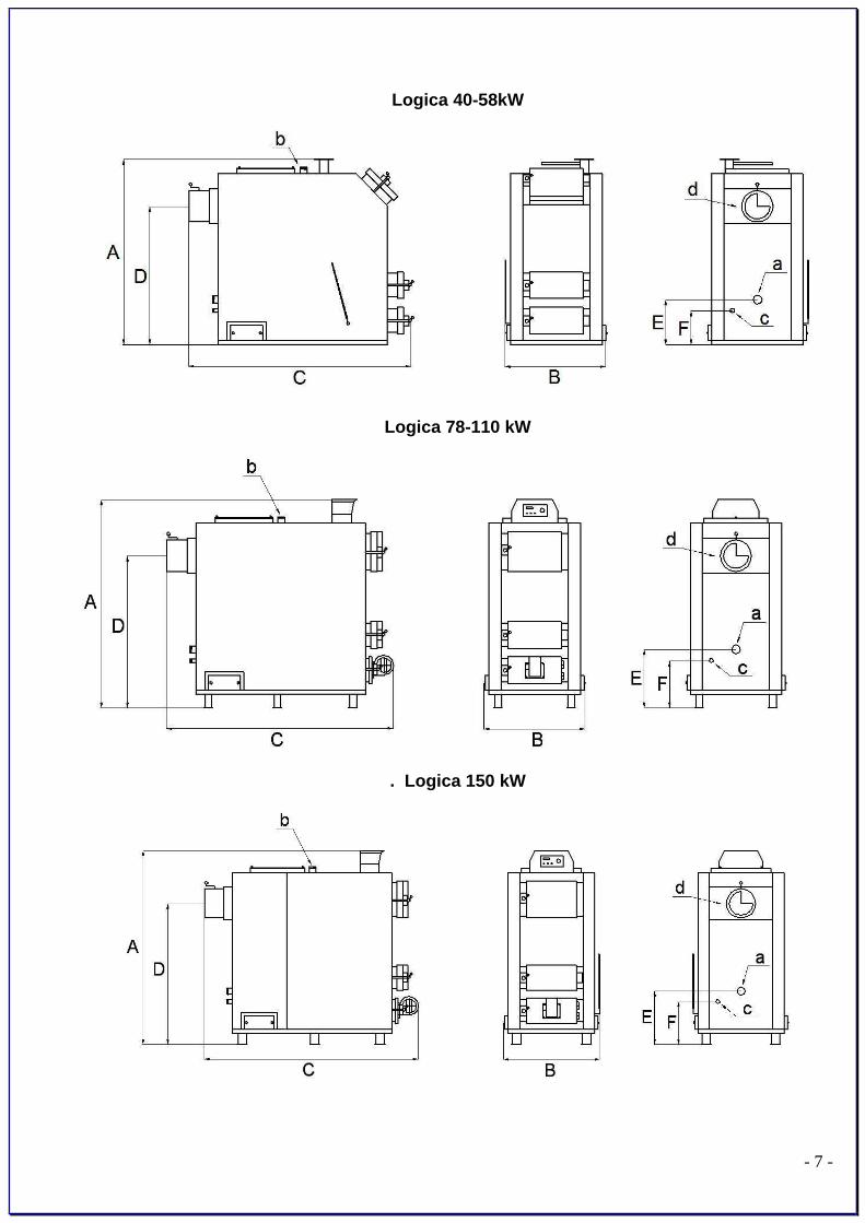
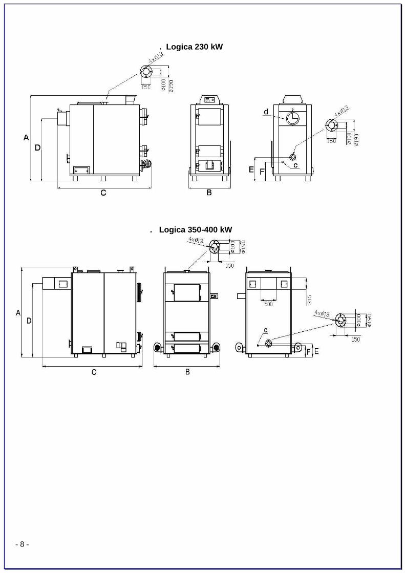
3.3) Dimensions of Logica:
Logica 17-20 20-27 30-38 40-48 50-58 70-78 100-110 150 200 350
A 1115 1115 1310 1350 1430 1620 1620 1740 1830 2350
B 610 660 720 760 810 830 930 1120 1250 2100
C 1490 1490 1670 1580 1640 1980 1980 2100 2200 3150
D 760 760 950 1035 1115 1270 1270 1370 1460 1930
E 255 255 255 270 270 400 400 400 430 360
F 220 220 215 230 230 360 360 360 230 310
G 930 930 1120 - - - - - - -
H 920 920 1120 - - - - - - -
a 1 ½” 2” 2” 2" 2" 2" 2" 2" rys. rys.
b 1 ½” 2” 2” 2" 2" 2" 2" 2" rys. rys.
c ½” ½” ½” ½” ½” ½” ½” ½” 3/4" 3/4"
d 160 160 195 235 235 285 285 285 298 rys.
e Gw ½” Gw ½” Gw ½” - - - - - - -
f Gz ½” Gz ½” Gz ½” - - - - - - -
Loading door corssection 210x290 210x340 210x390 210x440 210x490 300x400 300x500 300x600 300x600 430x770
. Logica 17-38kW
- 7 -
Logica 40-58kW
Logica 78-110 kW
. Logica 150 kW
- 8 -
. Logica 230 kW
. Logica 350-400 kW

- 9 -
3.4) Schematic diagram of work:
ventilator "H"
speed maximum speed of ventilator "d" "d"
speed near blowthroughs "E"
work work "P" work "P" work
ventilator
pause pause pause
"c" "c" "c"
T>Ts T<Ts
45 Ts Ts T<31oC
Phaze of emblazing Automatic work Blanking
Ts -set temperature
4) Controller RK 2001W – standard controller
� Schematic diagram of work:
ventilator "H"
speed maximum speed of ventilator "d" "d"
speed near blowthroughs "E"
work work "P" work "P" work
ventilator
pause pause pause
"c" "c" "c"
T>Ts T<Ts
45 Ts Ts T<31oC
Phaze of emblazing Automatic work Blanking
Ts -set temperature
- 10 -
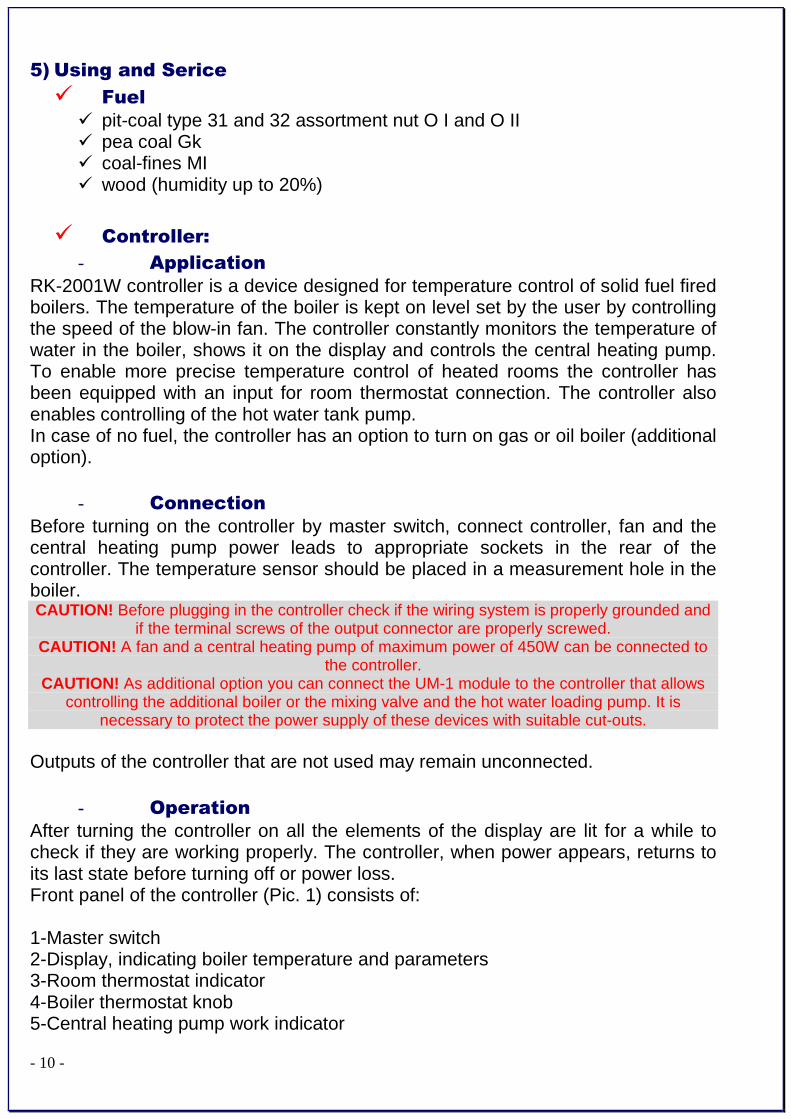
5) Using and Serice
� Fuel
� pit-coal type 31 and 32 assortment nut O I and O II � pea coal Gk � coal-fines MI � wood (humidity up to 20%)
� Controller:
- Application
RK-2001W controller is a device designed for temperature control of solid fuel fired boilers. The temperature of the boiler is kept on level set by the user by controlling the speed of the blow-in fan. The controller constantly monitors the temperature of water in the boiler, shows it on the display and controls the central heating pump. To enable more precise temperature control of heated rooms the controller has been equipped with an input for room thermostat connection. The controller also enables controlling of the hot water tank pump. In case of no fuel, the controller has an option to turn on gas or oil boiler (additional option).
- Connection
Before turning on the controller by master switch, connect controller, fan and the central heating pump power leads to appropriate sockets in the rear of the controller. The temperature sensor should be placed in a measurement hole in the boiler. CAUTION! Before plugging in the controller check if the wiring system is properly grounded and
if the terminal screws of the output connector are properly screwed. CAUTION! A fan and a central heating pump of maximum power of 450W can be connected to
the controller. CAUTION! As additional option you can connect the UM-1 module to the controller that allows
controlling the additional boiler or the mixing valve and the hot water loading pump. It is necessary to protect the power supply of these devices with suitable cut-outs.
Outputs of the controller that are not used may remain unconnected.
- Operation
After turning the controller on all the elements of the display are lit for a while to check if they are working properly. The controller, when power appears, returns to its last state before turning off or power loss. Front panel of the controller (Pic. 1) consists of: 1-Master switch 2-Display, indicating boiler temperature and parameters 3-Room thermostat indicator 4-Boiler thermostat knob 5-Central heating pump work indicator

- 11 -
6-STOP/choose parameters/erase alarms button 7-START/choose parameters button 8-Start programming /confirm parameters settings button 9-Hot water pump work indicator
Picture 1. Front panel of the RK-2001W controller
Basic operation of the controller is carried out by setting the desired temperature with boiler thermostat knob, other functions are carried out according to parameters programmed in service mode. The change in the boiler temperature setting is shown on the display for a few seconds, e.g. [C 55] and this value means the temperature of the water in the boiler which the controller will be trying to achieve. You can also check this value by pressing OK button for a short time. After pressing START button the fan starts to work and the control process begins. STOP button stops the fan for example to add fuel. If the controller is not in user or service mode the display shows water temperature in the boiler and the last character on the display defines the mode which the controller is currently in: for example: [50º-] - STOP mode [50ºC] - WORK mode
[50ºc] - hold up of burning in WORK mode [50ºU] – heating of hot water in SUMMER mode [50°u] - hold up of burning in SUMMER mode
[50ºd] – total bacteria control – heating up of hot water up to 75ºC.
- Setting up the user parameters.
Holding OK button enters the user mode and allows reviewing and is indicated by fast flashing of the room thermostat indicator. You can look through the parameters with < and > arrow buttons. After choosing the desired parameter you can switch to the change mode of the parameter by pressing OK button - it is indicated by the value of the parameter flashing. Change of the parameter is done by pressing - or + buttons. You can confirm new settings by pressing OK button and after that the controller allows choosing another parameter (with < > buttons). If you do not want to change the parameter value with the < or > button choose [End] and press OK or wait for 1 minute – the

- 12 -
controller will exit the user mode and will indicate the temperature of the water in the boiler
CAUTION: If in the controller the hot water pump is turned off, in the user menu, after pressing OK, you can only read the set temperature value of the boiler thermostat.
Table 1. Service parameters list
Display Parameter Min Max Step Factory default
C 40 Boiler desired temperature L 40 H 90 1˚C L 40
co C Central heating pump work when “C” (pump off when “-“)
- C C
cu u “d” heating up – total bacteria control in hot water tank
u d u
50˚ Water temperature in hot water tank
End Exit from user mode after pressing OK
1. Boiler work temperature
The boiler set temperature [C 40] – is the temperature which the controller will try to achieve in WORK mode. It is set by direct turning of the knob and is indicated by a short display.
2. Central heating pump work [co C] – WINTER/SUMMER mode – character “C” indicates that the central heating pump is working. In summer time the heating can be turned off by choosing the value “-“ with the (-) button which means turning off the central heating pump.
3. Total bacteria control in the hot water tank – heating up - the controller allows to manually launch the total bacteria control process in the boiler. Choosing the “d” value with (+) button starts the process in which the boiler is trying to achieve the temperature of 75˚C in the hot water tank. In order to start the total bacteria control process the boiler should be in WORK mode (this mode can be turned on by START button). E.g. [70˚d] will appear on the display. After reaching 75˚C in the hot water tank the controller will return to its state before choosing this option. CAUTION: the total bacteria control function can switched on at night when the water from the
hot water tank is not used to prevent the users from burn injury.
4. Water temperature readout in hot water tank [u50˚] – this parameter shows the measured temperature value in the hot water tank.
5. Exit from user mode – choosing the [End] on the display and pressing OK button causes exit from the parameter setting. Exit from this mode will also occur if no button is pressed for 1 minute.

- 13 -
- Parameter setting – the service mode
Holding OK button for more than 3 seconds enters the service mode where you can review and change the parameters. It is indicated by slow flashing of the room thermostat indicator. You can look through parameters with < and > arrow buttons. After choosing the desired parameter you can enter the parameter setting mode which is indicated by this value flashing. The change of the value will occur after pressing – or + button. Pressing OK button will confirm the changes. After that the controller allows choosing another parameter with < > buttons. If you do not want to change the parameter value with the < or > button we choose [End] and pres OK or wait for 1 minute – the controller will exit the service mode and will start indicating the temperature of the water in the boiler. Table 2. Service parameters list
Display Parameter Min Max Step Factory defaults
∏100 Fan max work power or max power when ∏r 0-10
50 100 10% 100
∏r 1 automatic fan speed control and time of
fan start --,0 10 1 1
∏n 5 Fan work time --,5 60 1s 5
∏u 6 Fan pause time 1 99 1min 6
P 40 Central heating pup launch temperature 30 70 1˚C 40
Ph 2 Central heating pup launch hysteresis 1 10 1˚C 2
Pc 2 Pause time of central heating pump with 30 sec. work periods
--,1 99 1min 2
u 50 Tap hot water desired temperature 30 60 1˚C 50
uh 5 hot water heating hysteresis 1 9 1˚C 5
ur 0 No hot water-0, hot water priority-1, no
hot water priority-2, mixing pump-3 0 2 1 0
L 40 Minimum boiler temperature 30 65 1˚C 40
H 90 Maximum boiler temperature 80 90 1˚C 90
h 5 Boiler temperature hysteresis 1 10 1˚C 5
A 99 Boiler overheating temperature 90 99 1˚C 99
Fd60 Fuel shortage testing time with burning,
increase by 5˚C 1 99 1min 60
Fb30 Fuel shortage testing time in WORK
mode and burning out. 1 99 1min 30
Ar 0 Additional output: 0-FUEL, 1-ALARM, 2-
MIX 0 2 1 0
Prod Return to factory defaults after pressing OK
outP Central heating pump output testing, press OK - launch
outP out1
out∏ Fan output testing, press OK - launch out∏ out2
outr Oil boiler launch output testing, press OK outr out3
- 14 -
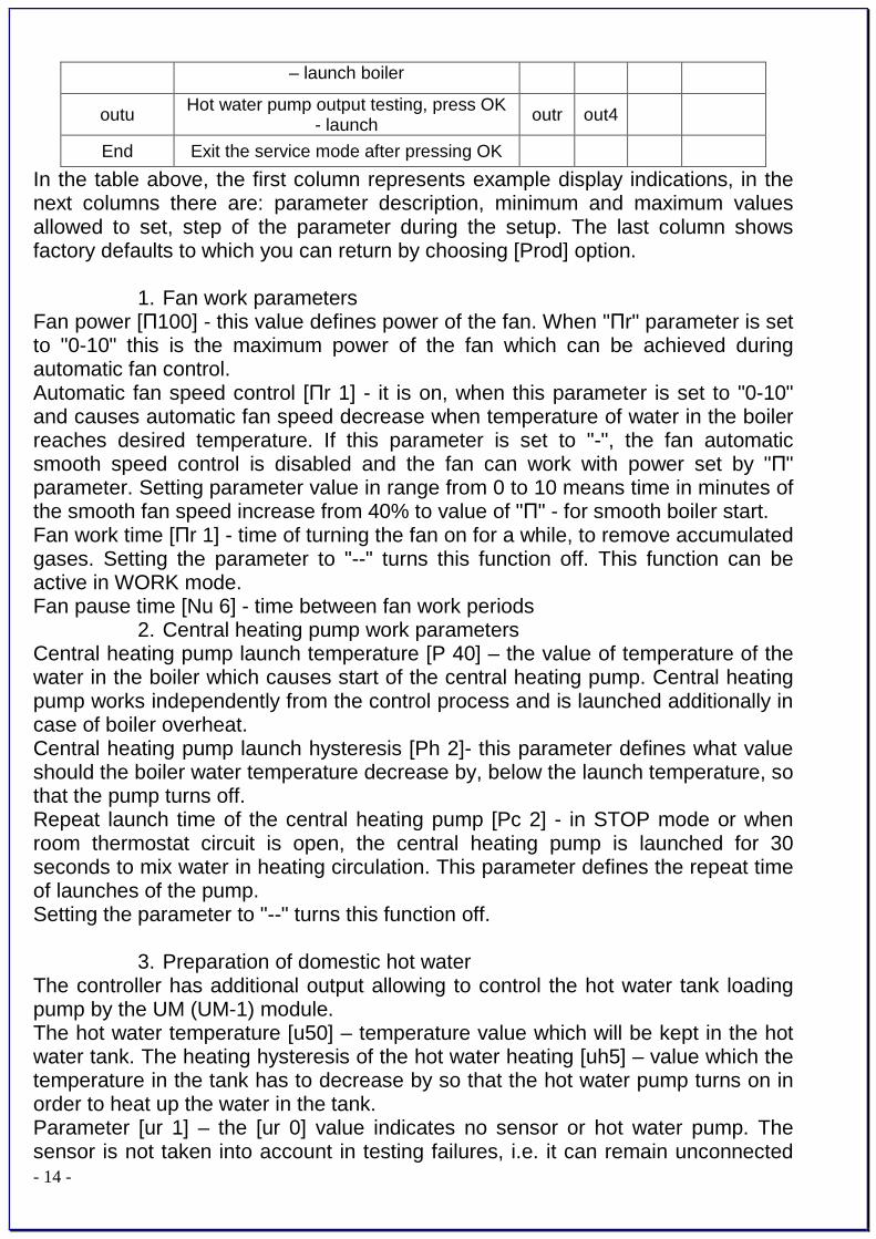
– launch boiler
outu Hot water pump output testing, press OK - launch
outr out4
End Exit the service mode after pressing OK
In the table above, the first column represents example display indications, in the next columns there are: parameter description, minimum and maximum values allowed to set, step of the parameter during the setup. The last column shows factory defaults to which you can return by choosing [Prod] option.
1. Fan work parameters Fan power [Π100] - this value defines power of the fan. When "Πr" parameter is set to "0-10" this is the maximum power of the fan which can be achieved during automatic fan control. Automatic fan speed control [Πr 1] - it is on, when this parameter is set to "0-10" and causes automatic fan speed decrease when temperature of water in the boiler reaches desired temperature. If this parameter is set to "-", the fan automatic smooth speed control is disabled and the fan can work with power set by "Π" parameter. Setting parameter value in range from 0 to 10 means time in minutes of the smooth fan speed increase from 40% to value of "Π" - for smooth boiler start. Fan work time [Πr 1] - time of turning the fan on for a while, to remove accumulated gases. Setting the parameter to "--" turns this function off. This function can be active in WORK mode. Fan pause time [Nu 6] - time between fan work periods
2. Central heating pump work parameters Central heating pump launch temperature [P 40] – the value of temperature of the water in the boiler which causes start of the central heating pump. Central heating pump works independently from the control process and is launched additionally in case of boiler overheat. Central heating pump launch hysteresis [Ph 2]- this parameter defines what value should the boiler water temperature decrease by, below the launch temperature, so that the pump turns off. Repeat launch time of the central heating pump [Pc 2] - in STOP mode or when room thermostat circuit is open, the central heating pump is launched for 30 seconds to mix water in heating circulation. This parameter defines the repeat time of launches of the pump. Setting the parameter to "--" turns this function off.
3. Preparation of domestic hot water The controller has additional output allowing to control the hot water tank loading pump by the UM (UM-1) module. The hot water temperature [u50] – temperature value which will be kept in the hot water tank. The heating hysteresis of the hot water heating [uh5] – value which the temperature in the tank has to decrease by so that the hot water pump turns on in order to heat up the water in the tank. Parameter [ur 1] – the [ur 0] value indicates no sensor or hot water pump. The sensor is not taken into account in testing failures, i.e. it can remain unconnected

- 15 -
and in the user parameter menu there is only the boiler thermostat set temperature displayed. [ur 1] value – hot water pump working with priority [ur 2] value – hot water tank working without priority [ur 3] value- means controlling of the returning water mixing pump in the boiler with the launch temperature of [u 50] and hysteresis [uh 5].
4. Setting of boiler work temperature range Minimum boiler temperature [L 40] - minimum temperature which can be set with the boiler thermostat knob. Maximum boiler temperature [H 90] - maximum temperature which can be set with the boiler thermostat knob. Boiler temperature hysteresis [h 5] - this parameter defines what value should temperature of water in the boiler decrease by, below temperature set with the thermostat knob, so that the fan turns on.
5. Protection against boiler overheating Boiler overheating temperature [A 99] - value, exceeding which causes permanent turn off of the fan to prevent boiler overheating. After the temperature increases above 80˚C the central heating pump is turned on to cool down the boiler. Overheating mode is shown by indicating error [E 2] on the display. It can be turned off by pressing STOP button, but only when temperature decreases below this temperature. Fan turn off also occurs in case of damage of the boiler temperature sensor which is shown on the display with error [E 1]. STB - the controller has additional protection against overheating which is independent from the processor. In case the temperature increases over 95°C, the control process is turned off by turning the fan off and launching the central heating pump. The fan and the pump are turned on to the control process again when temperature drops below 89°C. STB circuit enables more precise boiler work control and reduces overheating possibility.
6. No fuel No-fuel testing time during fuel firing start [Fd60] - after switching to WORK mode, if water temperature does not increase by 5°C in programmed time, the control process will be turned off and the display will show the message: [FUEL]. You can return to previous mode by pressing STOP button. No fuel testing time during fuel firing is finished after the set temperature is achieved. No-fuel testing time during work mode [Fb30] - in WORK mode, if temperature of water in the boiler decreases below temperature set with the thermostat, by hysteresis value, and does not increase by 5°C in the programmed time, the control process will be turned off and the display will show the message: [FUEL]. You can cancel the alarm by pressing STOP button.
7. Additional output

- 16 -
Additional output [Ar 0] – the controller has been equipped with an output that allows connection of the UM module. When the Ar parameter has the UM module value “0” it may control the oil or gas boiler – if such boiler exists in the heating circuit. After switching the controller with the main power switch the additional boiler is turned off and it turns on again when there is no fuel in the solid fuel boiler. This function is useful in heating systems where there is a solid fuel boiler used to cut the heating costs. After erasing the “no fuel” alarm by pressing STOP button the additional boiler is again turned off and the controller works again. Setting parameter [Ar] to “1” allows controlling the additional alarm signaling system with the UM module – which occurs on the controller. When Ar parameter is set to “2” the UM module allows controlling the mixing valve servo-motor in the central heating circuit depending on the room thermostat input. In this case the work of central heating pump depends only on the boiler temperature.
8. Factory defaults The controller allows returning to standard settings set by the producer by choosing [Prod] and pressing OK button. After activating this function, the controller sets each parameter showed in the table.
9. Output testing To make checking the controller work easier, it is possible to test output circuits which control the fan and the pump, and the additional boiler launching system. This function is available in service mode, only if the control process is off, i.e. the controller was in STOP mode before switching to service mode. By choosing [outP] on the display and pressing OK button you can turn on the central heating pump for a while, by choosing [outΠ] and pressing OK you can turn on the fan and by choosing [outr] and pressing OK you can turn the additional boiler on (if the additional module is connected). Choosing [outu] allows testing the hot water pump output.
10. Exiting service mode By choosing [End] option on the display and pressing OK button you can exit parameter setting mode. The controller also exits service mode, when no buttons are pressed for 1 minute.
- Additional functions
To improve comfort in heated rooms, the controller has been equipped with an input that allows connecting any kind of room thermostat with contact output. When temperature in the room is below desired temperature, the central heating pump is turned on and the room thermostat indicator is lit. It means that the boiler should keep temperature set by the room thermostat knob. After reaching desired temperature in the room, the room thermostat indicator turns off, the central heating pump is turned off and the boiler switches to mode in which it keeps burning at minimum temperature.

- 17 -
CAUTION. In case of not having room thermostat in the system, the room thermostat input
contacts must be short-circuited.
- Controller failures
The controller is constantly testing if its internal circuits and temperature sensor are working correctly. After detection of fault, it stops the fan, turns on the central heating pump and shows proper error message on the display. In case of failure please turn off the controller, plug the central heating pump to the power source, ensure appropriate fuel firing in the boiler and contact the service. When [E 1] error appears on the display, it means fault in the boiler sensor circuit or temperature below 0°C. [E 2] is displayed if boiler overheats. [E 3] error means fault and overheating at the same time. Appearing of [E 1] error on the display after erasing it by pressing STOP button, in spite of temperature decreasing below 90°C, may mean permanent damage of boiler temperature sensor (e.g. if the boiler has been overheated above 150°C). In case of programming the sensor and central heating pump in the service mode the controller tests the hot water sensor circuit. Appearing of fault [E8] means damage or lack of hot water sensor.
Picture. 2. RK-2001W connection diagram
- 18 -
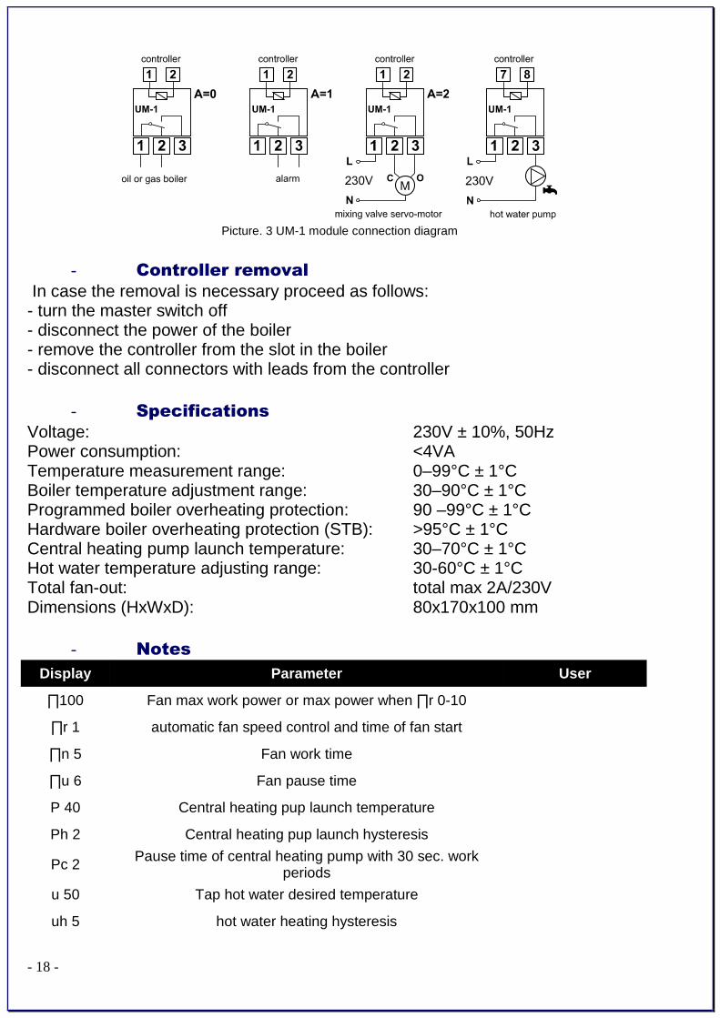
Picture. 3 UM-1 module connection diagram
- Controller removal
In case the removal is necessary proceed as follows: - turn the master switch off - disconnect the power of the boiler - remove the controller from the slot in the boiler - disconnect all connectors with leads from the controller
- Specifications
Voltage: 230V ± 10%, 50Hz Power consumption: <4VA Temperature measurement range: 0–99°C ± 1°C Boiler temperature adjustment range: 30–90°C ± 1°C Programmed boiler overheating protection: 90 –99°C ± 1°C Hardware boiler overheating protection (STB): >95°C ± 1°C Central heating pump launch temperature: 30–70°C ± 1°C Hot water temperature adjusting range: 30-60°C ± 1°C Total fan-out: total max 2A/230V Dimensions (HxWxD): 80x170x100 mm
- Notes
Display Parameter User
∏100 Fan max work power or max power when ∏r 0-10
∏r 1 automatic fan speed control and time of fan start
∏n 5 Fan work time
∏u 6 Fan pause time
P 40 Central heating pup launch temperature
Ph 2 Central heating pup launch hysteresis
Pc 2 Pause time of central heating pump with 30 sec. work periods
u 50 Tap hot water desired temperature
uh 5 hot water heating hysteresis

- 19 -
ur 0 No hot water-0, hot water priority-1, no hot water priority-2, mixing pump-3
L 40 Minimum boiler temperature
H 90 Maximum boiler temperature
h 5 Boiler temperature hysteresis
A 99 Boiler overheating temperature
Fd60 Fuel shortage testing time with burning, increase by 5˚C
Fb30 Fuel shortage testing time in WORK mode and burning
out.
Ar 0 Additional output: 0-FUEL, 1-ALARM, 2-MIX
6) System
6.1) Standards
• Heating System – during installation and operation of the boiler it is very important to keep safe distance from the inflammable materials. The boiler is allowed to work only in open type heating systems!
• Electrical installation – the boiler’s power supply is 230V/50Hz • Chimney – It must be done with respect to current norms and regulations.
Due boiler gasses temperature 90-100 C it is obligatory to put the INOX or other material tubes into the chimney. Required chimney draught is 0,1 – 0,2 mbar. Installation according to ADJ does entail some testing of the chimney, which may be carried out by a sweep
• Important sources of guidance installers: 98/37/EEG; 89/336/EEG; 73/23/EEG; EN 55014-1, 1993 /A1, 1997; EN 55014-1; EN 55014-2 C1 1998; EN 61000-3-2; EN 61000-4-2, -3-4-5-6-11, Level2; EN 50165; EN 50165 C1; EN 60335-1; EN 303-5; EN 12809; EN 13394
6.2) Localization of the boiler:
• Placing on flammable foundation. • place the boiler on non-flammable and thermal insulating pad which should protrude
not less than 20 mm outside boiler’s dimensions; • If the boiler is located in the basement it is required to place it on a base raised not
lower than 50 mm over floor’s level. The boiler and the fuel hopper must stand vertically and can be leveled using the regulating screw in fuel hopper’s leg.
• 1 000 mm of free space must be left in front of the boiler. • Minimal distance between back wall of the boiler and boiler room’s wall is 400 mm. • Minimum distance between free side of the boiler and boiler room’s wall is 100 mm. • The (230V/50Hz) electric socket should be easy to access.

- 20 -
6.3) Ventilation:
Appropriate supply and exhaust ventilation must be provided in the boiler room.
Accordantly with regulations each boiler room has to have the ventilation inlet and outlet in aim of assurance of correct boilers work and users safety. Lack of ventilation inlet or it’s stocking is the most frequent cause of incorrect work of boiler ( the fumidity, condense water, impossibility of higher temperature obtainment). Ventilation outlet has instead in task of offtake from room used air and harmful gases. In boiler room with chimney with natural draught it is not it allowed to use mechanical ventilation.
6.4) Chimney connection:
1. Cleaning door (Revision door) 2. Insulation. 3. Flexible connection (It should be
45°) Chimney should be done from
the steel >3mm.

- 21 -
6.4.1 Chimney connection
• Flues should be made in accordance with current regulations.
• To reduce the resistances of flow of flue gases the connection with chimney should be led in straight line and possible change of direction should be made with gentle arcs.
• Boilers can be assembled into flues from brick with aligned internal welds
• Combustion duct should begin from floor line
• About 30cm. over floor should be to situated cleanout with tight lock
• Intersection should be approximate to square with
regard on smaller resistances of flue gases flow • The minimum intersection of chimney amounts 20 x 20 cm • The dams of brick between duct and wall should not be smaller than 12 cm • Chimney should be led out over roof • The location of chimney outlet depends from the degree of roof droop and
stages of the flammability. The roof with angle of droop to 12º - the chimneys should stand over roof ridge 0.6m, roof with angle of droop over 12º - the chimneys should stand over roof ridge in case of easily flammable coverings 0,6m however in case of incombustible or difficultly flammable covering, the outlet can occur 0,3m over roof ridge.
• Assembly of draught regulator is recommended, which in case of too big underpressure in chimney opens and suck in the air from the boiler room and does not pull it through boiler causing the temperature uncontrolled rise. Interrupter this should be set on required value in dependence from power of boiler
- 22 -
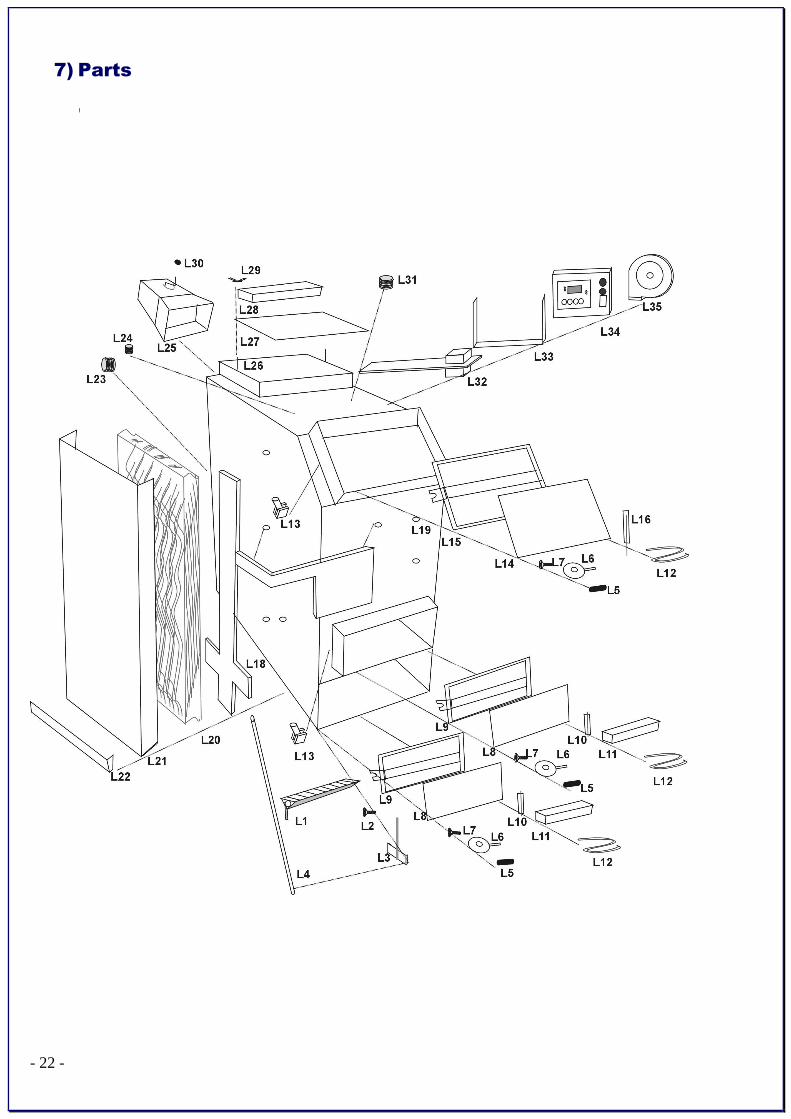
7) Parts

- 23 -
Symbol - code Description of the symbol
L1 Cast-iron grill L2 Assembling bolt of cast-iron grill L3 Mechanism of revolving grate L4 Grill shock pipe L5 Ebony handle of doors L6 Clamp to bottom doors L7 Assembling bolt of doors L8 Casing isolating doors from sheet metal 0,8 mm L9 Bottom doors
L10 Hinge of bottom doors L11 Ceramic plate L12 Sealing up doors string L13 Doors tightening element with screwed bolt L14 Isolating sheet metal of upper doors L15 Upper doors L16 Hinge of upper doors L18 Aerial duct L19 Aerial tube L20 Isolation from mineral wool L21 Isolating casing from sheet metal 0,8 mm L22 Cantilever angle profiles to assembly of casing of isolation L23 Return from screwed pipe 1/5" or 2" L24 Element to assembly of thermostat L25 The flue connection L26 Screwed bolt to assembly of upper cleanout L27 Upper cleanout L28 Ceramic upper plate L29 The butterfly-nut to assembly of upper cleanout. L30 Combustion throttle of flue connection ( regulating baffle) L31 Feeding from screwed pipe 1/5" or 2" L32 Aerial duct along with feeding assembly - plate L33 Fixing handle of control board L34 Butterfly-nut to assembly of control board L35 Electronic control board L36 Air fan

- 24 -
8) Boiler installation systems:
Logica must be installed with accumulation tank.
For 1kW it is round 50L water tank capacity – so for example for 20kW boiler
we need accumulation tank c.a. 1000 L.
PI
MN
Naczynie
wzbiorcze
RS
RP
RO
RB/RW
RW
RB
ZRC
ZT
OBIEG GRZEWCZY
GRZEJNIKOWY
F
ZZ
Pco
F
ZZ
Pco
SZ
OBIEG GRZEWCZY
PODŁOGOWY
CTco
ZTM
zasobnik c.w.u. FZZ RC
CTcwu
cwu
zwu
KS
MN
Pcwu F
CTco
UMS4
CTco
CTz
UMS-1
regulator
kotła
The water return should be kept always under 60ºC

- 25 -
9). Cleaning of the boiler:
Before start to clean logica, boiler must be switch ed of and cannot be warm. Remark, that 1mm of the dirties on the boiler’s wal ls means minimum 5% higher fuel consumption and lower efficiency. To clean logica it must be removed steel cover from the up and by the steel brush should be cleaned vertical canals. Ash will goes down and through the lower revision door it must be taken away.
Cleaning – example: Logica 17-38

- 26 -
PRODUCT WARRANTY
It is certified that the boiler has been inspected and tested for leaks under the pressure of 0.2 MPa by the producer and deemed suitable for operation. Provided the terms of transport, assembly, operation and maintenance of the boiler, contained in the service manual are observed, the producer grants to the purchaser a guarantee for failure-free operation of the device for 24 months from the date of purchase, however no longer than 36 months from the production date. (36 monthe for the boiler’s body and 24 month for electronic parts). The liability of the producer under this guarantee is limited to defects arising from causes inherent in the product – i.e. physical defects in the device. Any malfunctions or failures in the boiler’s operation resulting from inappropriate quality of the fuel used, or from assembly, choice of device or chimney non-compliant with service manual and applicable standards, or inappropriate chimney draught shall not be covered by this guarantee. The following boiler’s components: varnish coat, cast iron elements and movable elements shall be covered with a 12-month producer’s guarantee. The guarantee does not cover operating components such as sealant, gaskets, and chamotte bricks. Boiler’s burner, automatics and electrical fittings shall be covered with a 24-month guarantee. Electric connection to the boiler executed by a person without appropriate certification; unauthorised modification in the boiler’s construction, failure to conduct annual maintenance, lack of compulsory inspections or annotations on collection by service staff, or failure to settle the amounts due for the boiler’s repairs attributable to the customer’s fault shall void the guarantee. Damage to the control system arising from over voltage of the electrical system shall not be subject to guarantee. Rights under guarantee shall be exercised exclusively upon the seller’s sending to the producer of a correctly filled in boiler’s operation malfunction card and a copy of the device card. Should the device card be lost, the user shall be responsible for reproducing the card and filling it with appropriate contents.