logic developer process edition function blocks · edition and ge’s proficy* machine edition plc...
TRANSCRIPT

GEIntelligent Platforms
Logic Developer Process Edition Function BlocksDelivering increased precision and enabling advanced regulatory control strategies for continuous process control

2
Introduction
Process control in the most generic sense involves continuously controlling an operation or sequence of operations that changes the state of matter; specifically, this includes changing the state of energy, chemical composition, and/or physical dimension of a substance.
As complex programs need to interface with various aspects of a comprehensive production system, Logic Developer Process Edition function blocks from GE Intelligent Platforms add precision and ease of use to reduce the learning curve for engineers, enable higher operational efficiency, and lower development costs.
This white paper helps engineers and programmers explore the power provided by Logic Developer Process Edition function blocks that allow changes in the state of matter to be controlled to generate beneficial outputs that enhance life (e.g., fuel in, electricity out), and illustrates how businesses can use these function blocks to realize advanced regulatory control strategies. It also explains the differences between Logic Developer Process Edition and GE’s Proficy* Machine Edition PLC Logic Developer programming software, which is optimal for leveraging an integrated development environment for discrete, motion, and multi-target control applications.
Generic Examples
The following sections highlight examples where the Logic Developer Process Edition function block library adds value to any application.
The “Real” WorldThe control of continuous processes involves real quantities, which are expressed with real numbers. Logic Developer Process Edition function blocks operate using real numbers, whereas the Proficy Machine Edition (PME) instructions use mostly integers.
To properly tune a proportional integral derivative (PID) strategy, the PID parameters for the proportional gain, integral reset, and derivative time must be expressed in real numbers, which is pos-sible with the Logic Developer Process Edition PID and ADV_PID blocks. Many industry experts have noted poor tuning as the reason why processes underperform, which is a real concern given the movement toward green engineering and the efficient use of energy.
Real quantities as expressed in computer memory have a limited capacity for precision. Thus, user-defined functions using stan-dard PME instructions with floating point numbers could result in problems when totalizing, ramping, or integrating real quantities over time, because incremental quantities (the amount of chilled water delivered during this execution period of the controller) are dropped when summed with a large quantity (the running total of chilled water delivered thus far in a month).
Logic Developer Process Edition function blocks use an advanced technique to ensure that real numbers that are totalized or integrated over time do not lose precision—a very important advantage, especially when computing quantities that require a high resolution such as the amount of chilled water delivered to a customer. This technique has been disclosed for patent protection.
Time-Based CalculationsThe calculation of elapsed time is imperative for many real time functions, including PID, ADV_PID, RAMPSOAK, RATELIMIT, TOTALIZE, TIMED_EVT, and more. The calculation of time has been optimized in Logic Developer Process Edition function blocks. Furthermore, each Logic Developer Process Edition function block retains its individual calculation of elapsed time between executions, making it possible to schedule the execution of different function blocks at varying periods. This optimized feature of elapsed time is not a basic instruction or capability available in PME instructions.
Batch and SequencingRecognizing that sequential control is difficult to employ with the standard PME instruction set, Logic Developer Process Edition has added to its library sequential function blocks so that ordi-nary sequences and batch sequences can be realized.
Adaptive TuningThe real world changes with time, and the PME basic instruction set does not provide functions that take this fact into consider-ation. The good news is that the Logic Developer Process Edition blocks do. The advanced functions, ADAPT and SCHEDULER, allow users to configure control strategies that adapt to process conditions over time.
Logic Developer Process Edition Has Functions for Discrete Devices Too! The standard PME library has functions that allow for consistent control of discrete devices such as pumps, motors, valves, con-veyor belts and many other devices. Logic Developer Process Edition has DC2S (device control two state) and DC3S (device
Logic Developer Process Edition Function Blocks

3
control three state) blocks that provide advanced control for discrete devices. Fault detection, standardized faceplates, and multiple mode operation are available in Logic Developer Process Edition for discrete devices.
Batch InterfacesMany batch users struggle with devising an interface between the phase logic executing in the controller and the recipe phase executing on the batch server. Logic Developer Process Edition puts that struggle to a rest; it has a PLI block that interfaces with the batch server. It conforms to the S88 standard and makes phase logic construction easy.
Advanced Regulatory Control
As noted in the “Introduction” section, process control is very specific to transforming substances by altering their energy, chemical composition, or physical dimension. Over time, a set of advanced regulatory control algorithms that facilitate the controlled transformation of matter in the aforementioned methods occurs. The Logic Developer Process Edition function block library has the necessary functionality to easily construct
these control algorithms, whereas the standard PME library does not. The following sections will illustrate how to create the most common advanced regulatory control strategies with Logic Developer Process Edition function blocks.
Ratio ControlRatio control maintains the flow rate of one stream in a process at a defined proportion relative to that of another stream. Typically one stream fluctuates according to requirements of the process and is called the wild variable. The other variable is proportioned to the wild variable and is called the manipulated variable.
In Figure 1, Stream A represents the wild variable, and it is mea-sured by the flow transmitter FTA. The measured flow of Stream A is then multiplied by the desired ratio R, which yields the desired flow setpoint for Stream B. This setpoint is then passed to the flow controller FC.
The method of ratio control shown in Figure 1 is favored over methods that take the ratio of the measured streams and passes that as the process variable to a flow rate controller because it is more linear.
Figure 1 - Ratio Control P&ID

4
Figure 2 illustrates how the ratio control for the application shown in Figure 1 can be realized in Logic Developer Process Edition.
Ratio control is used in applications that require blending of two liquid streams such as pipeline mixer, reactant feeds to a reactor, burner air/fuel, and injecting modifiers.
Feedforward ControlFeedforward control measures known disturbances and manip-ulates the process so that the resulting effect the disturbance has on the process does not cause the controlled variable to deviate from its desired value. An example of manual feedforward control is when a driver of a vehicle increases his foot pressure
on the gas pedal when he sees an upcoming hill, which acts as a disturbance, before the hill’s slope causes the vehicle’s speed to dip below the desired value.
Feedforward control is typically utilized on processes with large known disturbances and/or large amounts of lag, because feed-back control is limited in its ability to provide satisfactory control in these cases. Obviously, feedforward control also requires measuring the disturbance.
The heat exchanger shown in Figure 3 is a process that can benefit from feedforward control. It has a measured disturbance (the inlet temperature, TTIN, and inlet flow, FTIN, of the process liquid) and large process lags.
Logic Developer Process Edition Function Blocks
Figure 2 - Ratio Control Strategy

5
Figure 3 - Feedforward Control P&ID
In order to build the feedforward control strategy for the pro-cess shown in Figure 3, we have to build a model of the process. Specifically, we need to determine the amount of steam flow required to keep TTOUT at setpoint as a function of the distur-bance given by changes in TTIN and FTIN. The model of choice for this application would be based on the energy balance around the heat exchanger. So for a liquid with a flow rate of ωin that is to be heated from temperature TTIN to TTOUT by steam with a flow rate of ωsteam the energy balance can be given as:
(1)
Cp is the heat capacity of the process liquid and λ is the latent heat given up by steam in condensing. Solving Equation (1) for the manipulated variable ωsteam yields:
(2)
In Equation (2),ωin is measured by FTIN , TTIN is measured,
TTOUT is the setpoint, and is a constant. Thus, we have our
steady state model of the process that gives us steam flow as a function of the measured disturbance and outlet temperature setpoint.
Now we need to take the dynamics of the process into consider-ation. Equation (2) gives the instantaneous steam flow required as a function of the inlet process liquid flow and temperature in order to keep the outlet temperature at setpoint, but the process will have dynamic elements that need to be consid-ered as well. In order to deal with these elements appropriately, lead-lag compensation must be introduced in the Feedforward Controller shown in Figure 3 to yield satisfactory control. Thus, Figure 4 shows the details of the Feedforward Controller. The lead time constant, τlead, should be equal to the time constant of the controlled variable in response to the manipulated variable, and the lag time constant, τlag, should equal the time constant of the controlled variable in response to the load. The constant K should convert steam flow into units and polarity compatible with the valve (i.e., the percent stoke on the valve that yields the required steam flow).

6
Pure feedforward control is never implemented in the real world because:
• Itdoesnotprovidecorrectiveactionforunmeasureddisturbances.
• Itdoesnotcompensateforinaccuraciesinprocessmodeling.
• Itdoesnothaveameanstodeterminewhetherthecontrolledvariable is moving away from setpoint.
The most common method for implementing feedforward con-trol in the real world is to use it in combination with feedback
control. In this scenario, the feedback controller will bias or trim the feedforward output to compensate for unmeasured disturbances and inaccuracies in modeling. This will keep the controlled variable from straying away from the setpoint. Figure 5 shows how to construct this feedforward/feedback control strategy in Logic Developer Process Edition. Notice in Figure 5 that the feedforward control signal is directly incorporated into the feedback controller (PID), thus manual/automatic transfer and anti-windup is applied to the combination of feedforward/feedback control without further configuration.
Logic Developer Process Edition Function Blocks
Figure 4 - Details of Feedforward Controller
Figure 5 - Feedforward Control with Feedback Trim Strategy

7
Other applications that can benefit from feedforward control include boiler drum level control, superheated steam temperature control, and feed control to a continuously stirred reactor tank.
Cascade ControlThe general concept of cascade control is to nest a secondary feedback loop inside a primary feedback loop in order to:
• Rejectdisturbancesinthesecondaryprocessvariablebeforethey have any effect on the primary process variable.
• Speeduptheresponseoftheprimaryfeedbackloop.
• Havethesecondaryfeedbackloophandlethenon-linearcharacteristics of the final control element, thus reducing their impact on the primary feedback loop.
An example of cascade control is given in Figure 6, where a fired furnace is used to heat a process fluid. In this example, the tem-perature of the process fluid (TT) is the primary process variable and the fuel flow (FT) is the secondary process variable. In the primary controller (TC), the primary process variable (TT) is sub-tracted from the operator setpoint to generate an error, which is used to determine the primary controller’s output by means of PID action. The primary controller’s output is the setpoint for the secondary controller (FC), which acts on the error between the remote setpoint generated from the primary controller and the secondary process variable (FT) by means of PID action to determine the position of the valve (FV). The position of the valve should be such that the primary process variable (TT) tends toward the operator setpoint.
Figure 6 - Cascade Control P&ID
8
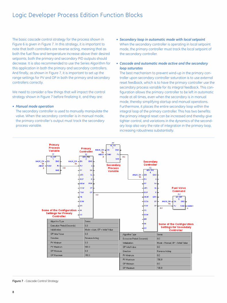
The basic cascade control strategy for the process shown in Figure 6 is given in Figure 7. In this strategy, it is important to note that both controllers are reverse acting, meaning that as both the fuel flow and temperature increase above their desired setpoints, both the primary and secondary PID outputs should decrease. It is also recommended to use the Series Algorithm for this application in both the primary and secondary controllers. And finally, as shown in Figure 7, it is important to set up the range settings for PV and OP in both the primary and secondary controllers correctly.
We need to consider a few things that will impact the control strategy shown in Figure 7 before finalizing it , and they are:
• Manualmodeoperation The secondary controller is used to manually manipulate the
valve. When the secondary controller is in manual mode, the primary controller’s output must track the secondary process variable.
• Secondaryloopinautomaticmodewithlocalsetpoint When the secondary controller is operating in local setpoint
mode, the primary controller must track the local setpoint of the secondary controller.
• Cascadeandautomaticmodeactiveandthesecondaryloopsaturates
The best mechanism to prevent wind-up in the primary con-troller upon secondary controller saturation is to use external reset feedback, which is to have the primary controller use the secondary process variable for its integral feedback. This con-figuration allows the primary controller to be left in automatic mode at all times, even when the secondary is in manual mode, thereby simplifying startup and manual operations. Furthermore, it places the entire secondary loop within the integral loop of the primary controller. This has two benefits: the primary integral reset can be increased and thereby give tighter control, and variations in the dynamics of the second-ary loop also vary the rate of integration in the primary loop, increasing robustness substantially.
Logic Developer Process Edition Function Blocks
Figure 7 - Cascade Control Strategy

9
Figure 8 illustrates how implementing these modifications impact the basic cascade control strategy pictured in Figure 7. The bubbles on the OR and SWITCH block’s inputs act as a NOT function, thus negating the input.
Figure 8 also shows how the advanced feature of external reset incorporated into the Logic Developer Process Edition’s ADV_PID block allows for the easy implementation of this optimized ver-sion of cascaded control.
Cascade control is used in many different applications, including jacketed reactor temperature control, slurry feed to column, and catalyst regeneration system.
Override ControlOverride control involves two or more independent PID loops used to manipulate one process device such as a modulating valve. The PID loop calling for the greatest corrective action in
a pre-defined safe direction will override the other PID loops. Typically, this control is used where there is a primary process variable to be controlled with a constraint; e.g., regulating a temperature with the constraint of not allowing a pressure to fall below its minimum value.
For example, consider the process pictured in Figure 9, where a hot saturated liquid enters a tank and from there is pumped under flow control back to the process. Under normal operation, the level in the tank is at height h1. If, under any circumstances, the liquid level drops below the height h2, the liquid will not have enough net positive suction head (NPSH), and cavitation at the pump will result. It is therefore necessary to design a control scheme that avoids this condition, hence the need for override control. So for this process, the primary control objective is to control the flow of liquid back to the process to a given setpoint with the constraint of not allowing the liquid in the tank to go below h2.
Figure 8 - Modified Cascade Control Strategy

10
Figure 9 - Override Control P&ID
Figure 10 - Override Control Strategy
Logic Developer Process Edition Function Blocks

GE Intelligent Platforms Contact Information
Americas: 1 800 433 2682 or 1 434 978 5100 Global regional phone numbers are listed by location on our web site at www.ge-ip.com/contact
www.ge-ip.com
03.10 GFT-773©2010 GE Intelligent Platforms, Inc. All rights reserved. *Trademark GE Intelligent Platforms, Inc.All other brands or names are property of their respective holders.
Figure 10 illustrates an override control strategy using Logic Developer Process Edition function blocks for the process pic-tured in Figure 9. The OVERRIDE function block shown in the figure can be configured to pass the minimum, maximum, or median input to its output; hence for this example, it will be con-figured to pass the minimum. It also interfaces with the ADV_PID blocks to ensure that the unselected controller does not wind up or down, thus limiting its responsiveness.
Override control can be applied to solve many control problems such as found with the control of distillation columns, fired heat-ers, chemical reactors, and compressors.
Summary
Whereas PME PLC Logic Developer is a powerful development tool for the integration between discrete, motion and multi-target control, Logic Developer Process Edition provides key advantages for programmers and engineers in continuous process applications. As this paper illustrates, Logic Developer Process Edition function blocks deliver increased precision and ease of use, and provide the functionality necessary to construct control algorithms for the most common advanced regulatory control strategies—simplifying development efforts for a sus-tainable competitive advantage.