lockline gas springs - aero materiel ab · design and functionality of lockable gas springs gas...
TRANSCRIPT

Lockline Gas SpringsVarilock – Lockable gas springs and accessories
www.suspa.com
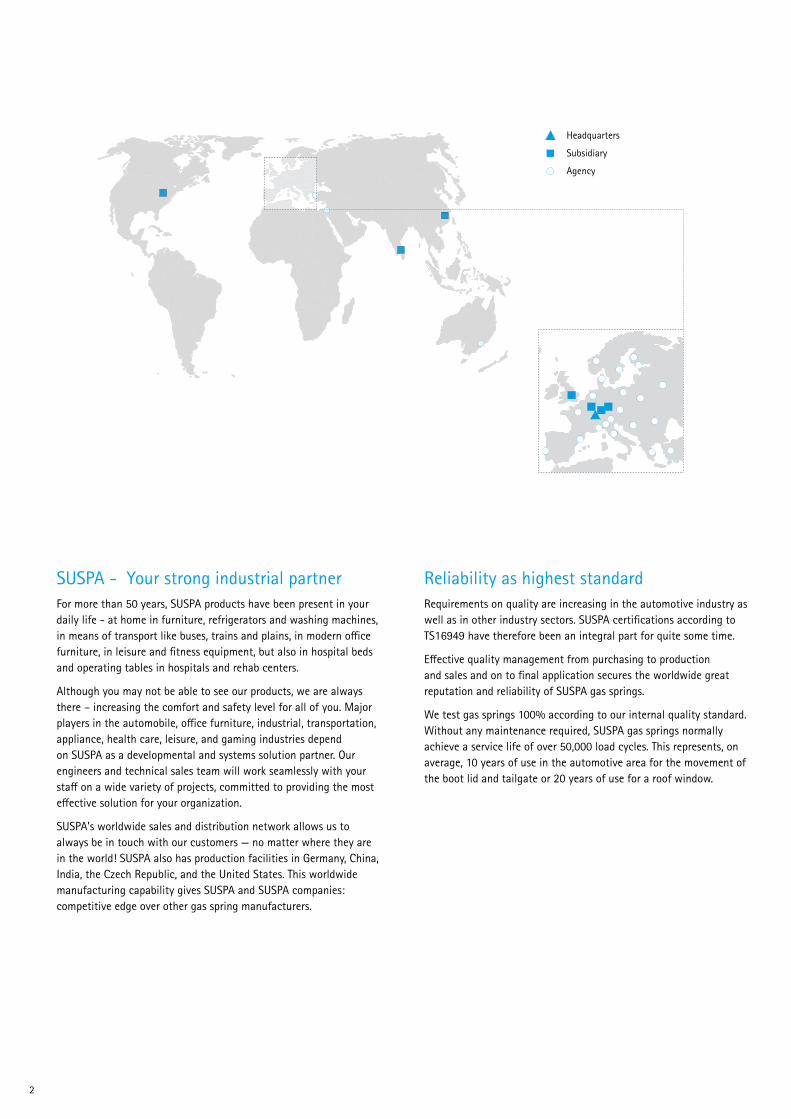
Headquarters
Subsidiary
Agency
SUSPA - Your strong industrial partnerFor more than 50 years, SUSPA products have been present in your daily life - at home in furniture, refrigerators and washing machines, in means of transport like buses, trains and plains, in modern office furniture, in leisure and fitness equipment, but also in hospital beds and operating tables in hospitals and rehab centers.
Although you may not be able to see our products, we are always there – increasing the comfort and safety level for all of you. Major players in the automobile, office furniture, industrial, transportation, appliance, health care, leisure, and gaming industries depend on SUSPA as a developmental and systems solution partner. Our engineers and technical sales team will work seamlessly with your staff on a wide variety of projects, committed to providing the most effective solution for your organization.
SUSPA’s worldwide sales and distribution network allows us to always be in touch with our customers — no matter where they are in the world! SUSPA also has production facilities in Germany, China, India, the Czech Republic, and the United States. This worldwide manufacturing capability gives SUSPA and SUSPA companies: competitive edge over other gas spring manufacturers.
Reliability as highest standardRequirements on quality are increasing in the automotive industry as well as in other industry sectors. SUSPA certifications according to TS16949 have therefore been an integral part for quite some time.
Effective quality management from purchasing to production and sales and on to final application secures the worldwide great reputation and reliability of SUSPA gas springs.
We test gas springs 100% according to our internal quality standard. Without any maintenance required, SUSPA gas springs normally achieve a service life of over 50,000 load cycles. This represents, on average, 10 years of use in the automotive area for the movement of the boot lid and tailgate or 20 years of use for a roof window.
2
3
Contents
Design, functionality and features 4-5
Basic range: technical dataElastic locking, rigid locking
6-7
Special functionsAntiShock, EasySwitch, OverRide, TimeReset, ComfortRelease
8-9
Release SystemsRelease mechanism, bowden cables and release levers
10-11
End fittingsJoint eyelets and fork heads
12
SUSPA expertise in system solutionsComponents, height-adjustable table columns VariStand and VariBase
13-15
Areas of application and client references 16-17
SUSPA - Your development partner 18
Technical advice 19
www.suspa.com/uk/products/locking-gas-springs
Lockline 3
Design and functionality of lockable gas springs
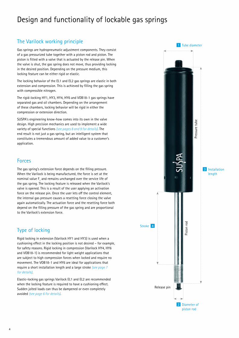
Gas springs are hydropneumatic adjustment components. They consist of a gas pressurized tube together with a piston rod and piston. The piston is fitted with a valve that is actuated by the release pin. When the valve is shut, the gas spring does not move, thus providing locking in the desired position. Depending on the pressure medium, this locking feature can be either rigid or elastic.
The locking behavior of the EL1 and EL2 gas springs are elastic in both extension and compression. This is achieved by filling the gas spring with compressible nitrogen.
The rigid-locking HY1, HY3, HY4, HY6 and VOB18-1 gas springs have separated gas and oil chambers. Depending on the arrangement of these chambers, locking behavior will be rigid in either the compression or extension direction.
SUSPA’s engineering know-how comes into its own in the valve design. High precision mechanics are used to implement a wide variety of special functions (see pages 8 and 9 for details). The end result is not just a gas spring, but an intelligent system that constitutes a tremendous amount of added value to a customer’s application.
The gas spring’s extension force depends on the filling pressure. When the Varilock is being manufactured, the force is set at the nominal value F1 and remains unchanged over the service life of the gas spring. The locking feature is released when the Varilock’s valve is opened. This is a result of the user applying an activation force on the release pin. Once the user lets off the control element, the internal gas pressure causes a resetting force closing the valve again automatically. The actuation force and the resetting force both depend on the filling pressure of the gas spring and are proportional to the Varilock’s extension force.
Rigid locking in extension (Varilock HY1 and HY3) is used when a cushioning effect in the locking position is not desired – for example, for safety reasons. Rigid locking in compression (Varilock HY4, HY6 and VOB18-1) is recommended for light weight applications that are subject to high compression forces when locked and require no movement. The VOB18-1 and HY6 are ideal for applications that require a short installation length and a large stroke (see page 7 for details).
Elastic-locking gas springs Varilock EL1 and EL2 are recommended when the locking feature is required to have a cushioning effect. Sudden jolted loads can thus be dampened or even completely avoided (see page 6 for details).
The Varilock working principle
Forces
Type of locking
1
2
3
4
Tube diameter
Diameter of piston rod
Pist
on ro
d
Release pin
Pres
sure
tube
Installation length
Stroke
4
5
Features of lockable gas springs
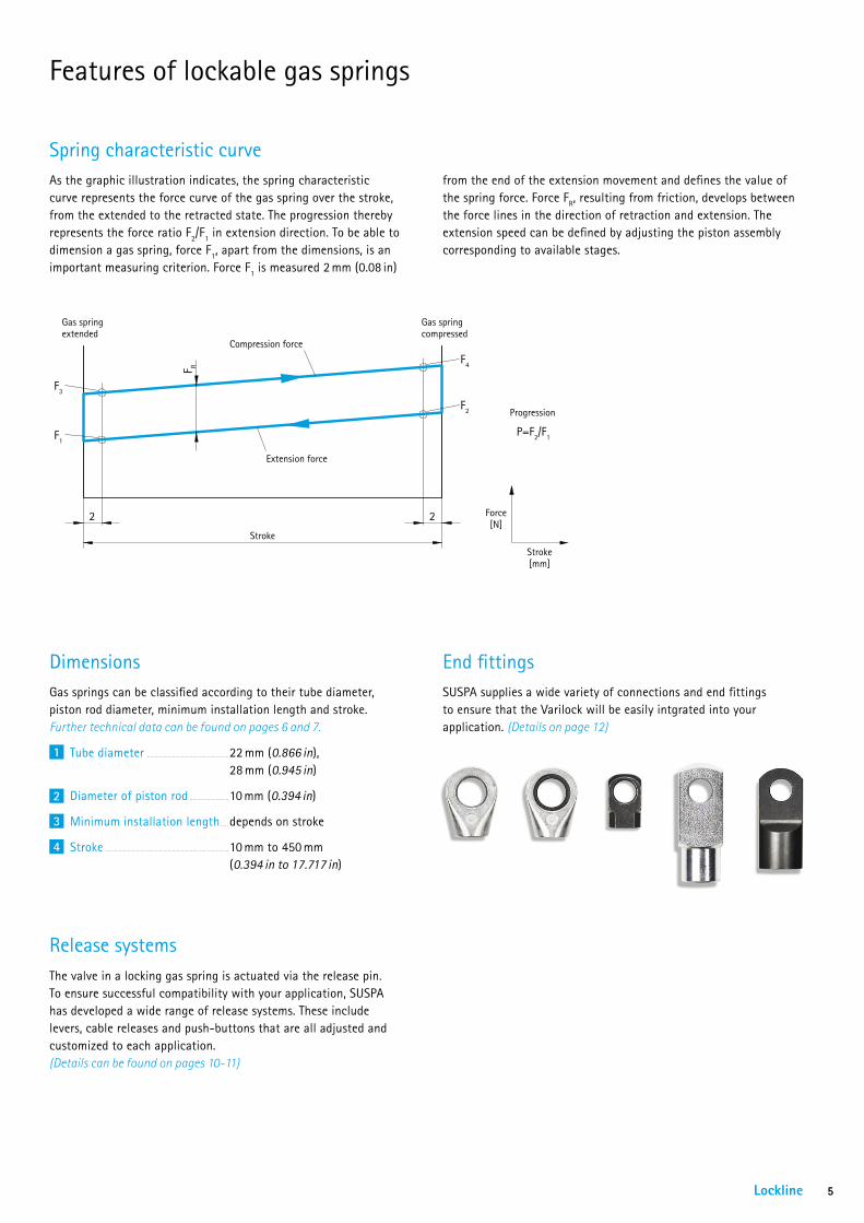
As the graphic illustration indicates, the spring characteristic curve represents the force curve of the gas spring over the stroke, from the extended to the retracted state. The progression thereby represents the force ratio F2/F1 in extension direction. To be able to dimension a gas spring, force F1, apart from the dimensions, is an important measuring criterion. Force F1 is measured 2 mm (0.08 in)
The valve in a locking gas spring is actuated via the release pin. To ensure successful compatibility with your application, SUSPA has developed a wide range of release systems. These include levers, cable releases and push-buttons that are all adjusted and customized to each application. (Details can be found on pages 10-11)
SUSPA supplies a wide variety of connections and end fittings to ensure that the Varilock will be easily intgrated into your application. (Details on page 12)
Spring characteristic curve
Release systems
End fittingsGas springs can be classified according to their tube diameter, piston rod diameter, minimum installation length and stroke. Further technical data can be found on pages 6 and 7.
Tube diameter 22 mm (0.866 in), 28 mm (0.945 in)
Diameter of piston rod 10 mm (0.394 in)
Minimum installation length depends on stroke
Stroke 10 mm to 450 mm (0.394 in to 17.717 in)
Dimensions
1
2
3
4
Gas spring extended
Gas spring compressed
Compression force
Extension force
Stroke
Stroke [mm]
Force [N]
Progression
2 2
F1
F2
P=F2/F1
F R
F3
F4
from the end of the extension movement and defines the value of the spring force. Force FR, resulting from friction, develops between the force lines in the direction of retraction and extension. The extension speed can be defined by adjusting the piston assembly corresponding to available stages.
Lockline 5
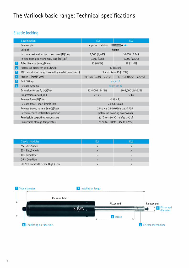
The Varilock basic range: Technical specifications
Elastic locking
Special modules EL1 EL2
AS - AntiShock x x
ES - EasySwitch x x
TR - TimeReset - -
OR - OverRide - -
CH / CL ComfortRelease High / Low x x
3 Installation length
4 Stroke
2 Piston rod diameter
1 Tube diameter
5 End fitting on tube side 6 Release mechanism
Piston rod Release pin
Pressure tube
Specification EL1 EL2
Release pin on piston rod side
Locking elastic
In compression direction: max. load [N]/(lbs) 6,500 (1,460) 10,000 (2,245)
In extension direction: max. load [N]/(lbs) 3,500 (785) 7,000 (1,572)
1 Tube diameter [mm]/(inch) 22 (0.866) 28 (1.102)
2 Piston rod diameter [mm]/(inch) 10 (0.394)
3 Min. installation length excluding eyelet [mm]/(inch) 2 x stroke + 70 (2.756)
4 Stroke C [mm]/(inch) 10 - 339 (0.394-13.346) 10 - 450 (0.394 - 17.717)
5 End fittings page 12
6 Release systems pages 10-11
Extension forces F1 [N]/(lbs) 80 - 800 (18-180) 80-1,000 (18-225)
Progression ratio (F2/F1) < 1.25 < 1.2
Release force [N]/(lbs) 0.25 x F1
Release travel, short [mm]/(inch) < 0.5 (< 0.02)
Release travel, normal [mm]/(inch) 2.5 ≤ x ≤ 3.5 (0.098 ≤ x ≤ 0.138)
Recommended installation position piston rod pointing downwards
Permissible operating temperature -20 °C to +60 °C (-4°F to 140°F)
Permissible storage temperature -20 °C to +80 °C (-4°F to 176°F)
6

Rigid locking
Specification HY1 HY3 HY4 HY6 VOB18-1
Release pin
Locking rigid in tensile direction rigid in compressive directionIn compression direction: rigid to [N]/(lbs) / max. load [N]/(lbs)
3.6 x F1 / 6,500 (3.6 x F1 / 1,460)
5.8 x F1 / 10,000 (5.8 x F1 / 2,245)
10,000 (2,245)
1,200 (270)
3,000 (673)
In extension direction: rigid to [N]/(lbs) / max. load [N]/(lbs)
3,500 (785)
7,000 (1,572)
4.8 x F1 / 7,000 (4.8 x F1 / 1,572)
1.6 x F1 1.5 x F1
1 Tube diameter [mm]/(inch) 22 (0.866) 28 (1.102)
2 Piston rod diameter [mm]/(inch) 10 (0.394)
3 Min. installation length excluding eyelet [mm]/(inch)
2.6 x stroke + 76 (2.992)
2.4 x stroke + 76 (2.992)
2.6 x stroke + 85 (3.346)
2 x stroke + 110 (4.331)
2 x stroke + 90 (3.543)
4 Stroke C [mm]/(inch) 10 - 300 (0.394 - 11.811)
10 - 450 (0.394 - 17.717)
10 - 300 (0.394 - 11.811)
10 - 450 (0.394 - 17.717)
20 - 300 (0.787 - 11.811)
5 End fittings Page 12
6 Release mechanism Pages 10-11
Extension forces F1 [N]/(lbs) 80 - 800 (18 - 180)
80 - 1,000 (18 - 225)
70 - 400 (16 - 90)
150 - 1,000 (34 - 225)
Progression ratio (F2/F1) < 1.6 < 1.5 < 1.6 < 1.6 < 1.7
Release force [N]/(lbs) 0.25 x F1 0.4 x F1
Release travel, short [mm]/(inch) < 0.5 (0.020) -
Release travel, normal [mm]/(inch) 2.5 ≤ x ≤ 3.5 (0.098 ≤ x ≤ 0.138)Recommended installation position any any piston rod pointing
downwardsany piston rod pointing
downwardsPermissible operating temperature -20°C to +60°C
(-4°F to 140°F)-10°C to +60°C (14°Fto140°F)
-20°C to +60°C (-4°F to 140°F)
Permissible storage temperature -20°C to +80°C (-4°F to 176°F)
Special modules HY1 HY3 HY4 HY6 VOB18-1
AS - AntiShock x x x - -
ES - EasySwitch x x x - -
TR - TimeReset - x x - -
OR - OverRide - - - x -
CH / CL ComfortRelease High / Low x x x x -
on piston rod side on tube side
Lockline 7

Special functions
The “AntiShock” module detects the load situation of the application and acts accordingly. When used in an office chair with dynamic free-swinging, the Varilock with AntiShock provides the user with smooth moving action (comfort function). In addition, it will return the non-loaded backrest slowly from the reclined to the vertical position when released. Thus it will avoid the so-called catapult effect (safety function).
In the case of height-adjustable tables which have a low intrinsic weight but are subjected to high loads when in use (Varilock with a high extension force), the Varilock allows a quick height adjustment of the loaded table and, thanks to AntiShock, also prevents the tabletop rising up too quickly when the empty, unloaded table is released.
With the “EasySwitch“ module, the user controls the valve “digitally”, alternating between the closed and permanently open position and back again. You switch between the two modes by activating the pin through the release mechanism.
With EasySwitch, the valve stays either open (swinging function) or closed (locked backrest) as per the user’s settings.
The “OverRide“ module allows a person to move the application in the extension direction without having to activate the release function. In the case of desk or table applications, a gentle upwards force applied to the tabletop adjusts the height of the table. Once the desired position has been achieved, locking in the compression direction is rigid.
OverRide provides smooth, comfortable operation and was first designed for use in hospital beds and over-bed tables. It also allows for single-hand operation of the application.
AntiShock AS: comfort and safety combined
EasySwitch ES: locking that can be switched on and of
OverRide OR: smooth extension without actuation
»CLICK«
8
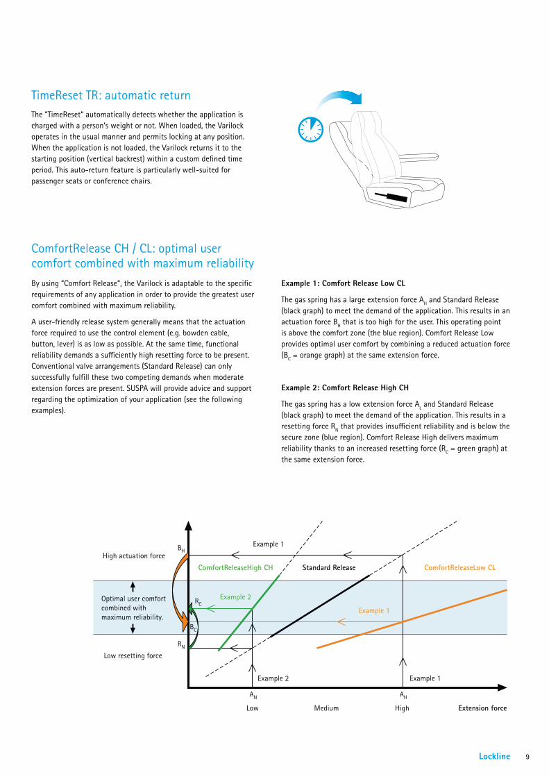
The “TimeReset“ automatically detects whether the application is charged with a person’s weight or not. When loaded, the Varilock operates in the usual manner and permits locking at any position. When the application is not loaded, the Varilock returns it to the starting position (vertical backrest) within a custom defined time period. This auto-return feature is particularly well-suited for passenger seats or conference chairs.
By using “Comfort Release“, the Varilock is adaptable to the specific requirements of any application in order to provide the greatest user comfort combined with maximum reliability.
A user-friendly release system generally means that the actuation force required to use the control element (e.g. bowden cable, button, lever) is as low as possible. At the same time, functional reliability demands a sufficiently high resetting force to be present. Conventional valve arrangements (Standard Release) can only successfully fulfill these two competing demands when moderate extension forces are present. SUSPA will provide advice and support regarding the optimization of your application (see the following examples).
Example 1: Comfort Release Low CL
The gas spring has a large extension force AH and Standard Release (black graph) to meet the demand of the application. This results in an actuation force BH that is too high for the user. This operating point is above the comfort zone (the blue region). Comfort Release Low provides optimal user comfort by combining a reduced actuation force (BC = orange graph) at the same extension force.
Example 2: Comfort Release High CH
The gas spring has a low extension force AL and Standard Release (black graph) to meet the demand of the application. This results in a resetting force RN that provides insufficient reliability and is below the secure zone (blue region). Comfort Release High delivers maximum reliability thanks to an increased resetting force (RC = green graph) at the same extension force.
TimeReset TR: automatic return
ComfortRelease CH / CL: optimal user comfort combined with maximum reliability
High actuation force
Low resetting force
Low Medium High
BH
AN AH
RN
BC
RCExample 2
Example 1
Example 1
Optimal user comfortcombined withmaximum reliability.
Example 2 Example 1
ComfortReleaseHigh CH Standard Release
Extension force
ComfortReleaseLow CL
Lockline 9

Release systems
SusflexDirectfor lever release
Type 1 + 2 Type 3
Release head with bowden cable
Release head with lever
Type Eyelet 8 mm (0.315 in)
Eyelet 10 mm (0.394 in)
Comments
1 02100075 02150102 standard lever2 02150103 02160004 lever can be locked3 06552018 06552017 for table application
L
SusflexSide90° release: cable mounted perpendicular to gas spring
Force ratio Eyelet 8 mm (0.315 in)
Eyelet 10 mm (0.394 in)
1:2 02152022 02152021
Optimize your application: Configure your individual release system choosing a release lever, release mechanism and the length of the bowden cable.
SusflexRegularaxial release: cable mounted parallel to gas spring
Force ratio Eyelet 8 mm (0.315 in)
Eyelet 10 mm (0.394 in)
1:2 02150106 02150107
L
SusflexMultiaxial release with higher force ratio
Force ratio Eyelet 8 mm (0.315 in)
Eyelet 10 mm (0.394 in)
Comments
1:6 02152005 021520081:10 02152006 02152009
1:20 02152007 021520101:6 02152015 02152018 with resetting
spring*1:10 02152016 02152019 with resetting
spring*1:20 02152017 02152020 with resetting
spring*
* Recommended for low actuation forces in order to help achieve complete resetting of the actuation element.
L
10
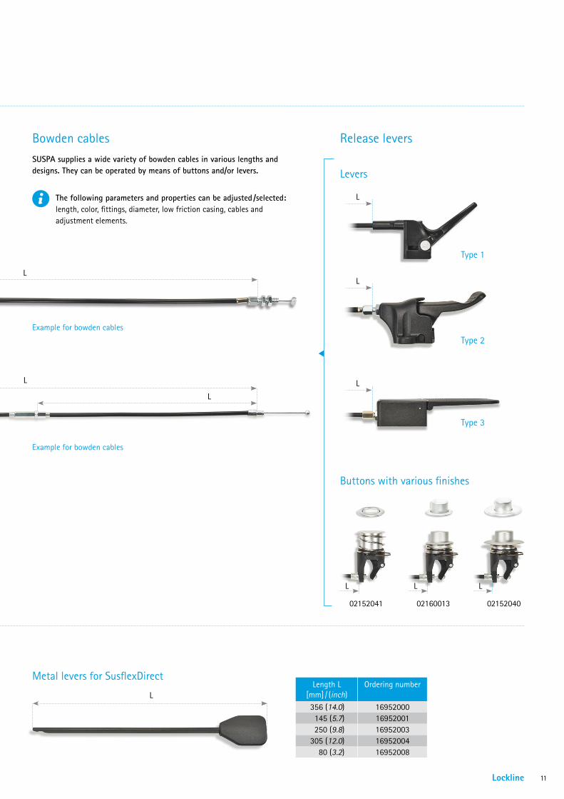
Bowden cables Release levers
Levers
Metal levers for SusflexDirect
SUSPA supplies a wide variety of bowden cables in various lengths and designs. They can be operated by means of buttons and/or levers.
The following parameters and properties can be adjusted /selected: length, color, fittings, diameter, low friction casing, cables and adjustment elements.
Example for bowden cables
L
Example for bowden cables
Die Ausführung des Bowdenzuges wird durch die gewählte Betätigungseinheit, die Auslösemechanik und die vom Kunden vorgegebene Länge L definiert.
L
L
L
Buttons with various finishes
02152041 02160013 02152040
Type 3
L
Length L [mm] / (inch)
Ordering number
356 (14.0) 16952000145 (5.7) 16952001250 (9.8) 16952003
305 (12.0) 1695200480 (3.2) 16952008
Type 1
L
L L L
Type 2
L
Lockline 11
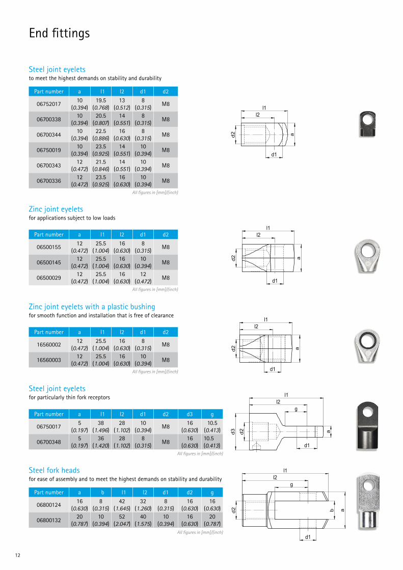
End fittings
Steel joint eyeletsto meet the highest demands on stability and durability
All figures in [mm]/(inch)
Part number a l1 l2 d1 d2
0675201710
(0.394)19.5
(0.768)13
(0.512)8
(0.315)M8
0670033810
(0.394)20.5
(0.807)14
(0.551)8
(0.315)M8
0670034410
(0.394)22.5
(0.886)16
(0.630)8
(0.315)M8
0675001910
(0.394)23.5
(0.925)14
(0.551)10
(0.394)M8
0670034312
(0.472)21.5
(0.846)14
(0.551)10
(0.394)M8
0670033612
(0.472)23.5
(0.925)16
(0.630)10
(0.394)M8
Zinc joint eyeletsfor applications subject to low loads
All figures in [mm]/(inch)
All figures in [mm]/(inch)
Part number a l1 l2 d1 d2
0650015512
(0.472)25.5
(1.004)16
(0.630)8
(0.315)M8
0650014512
(0.472)25.5
(1.004)16
(0.630)10
(0.394)M8
0650002912
(0.472)25.5
(1.004)16
(0.630)12
(0.472)M8
Zinc joint eyelets with a plastic bushingfor smooth function and installation that is free of clearance
Part number a l1 l2 d1 d2
1656000212
(0.472)25.5
(1.004)16
(0.630)8
(0.315)M8
1656000312
(0.472)25.5
(1.004)16
(0.630)10
(0.394)M8
Steel joint eyeletsfor particularly thin fork receptors
Alle Angaben in mm.
All figures in [mm]/(inch)
Part number a l1 l2 d1 d2 d3 g
067500175
(0.197)38
(1.496)28
(1.102)10
(0.394)M8
16 (0.630)
10.5 (0.413)
067003485
(0.197)36
(1.420)28
(1.102)8
(0.315)M8
16 (0.630)
10.5 (0.413)
Steel fork heads for ease of assembly and to meet the highest demands on stability and durability
Alle Angaben in mm.
All figures in [mm]/(inch)
Part number a b l1 l2 d1 d2 g
0680012416
(0.630)8
(0.315)42
(1.645)32
(1.260)8
(0.315)16
(0.630)16
(0.630)
0680013220
(0.787)10
(0.394)52
(2.047)40
(1.575)10
(0.394)16
(0.630)20
(0.787)
d2 a
d1
l2 l1
l2 l1
d1
a
d2
d2 a
d1
l2 l1
d2
d3
g
d1
a
l2 l1
d2
d1
b
a
g l2
l1
d2 a
d1
l2 l1
l2 l1
d1
a
d2
d2 a
d1
l2 l1
d2
d3
g
d1
a
l2 l1
d2
d1
b
a
g l2
l1
d2 a
d1
l2 l1
l2 l1
d1
a
d2
d2 a
d1
l2 l1
d2
d3
g
d1
a
l2 l1
d2
d1
b
a
g l2
l1
d2 a
d1
l2 l1
l2 l1
d1
a
d2
d2 a
d1
l2 l1
d2
d3
g
d1
a
l2 l1
d2
d1
b
a
g l2
l1
d2 a
d1
l2 l1
l2 l1
d1
a
d2
d2 a
d1
l2 l1
d2
d3
g
d1
a
l2 l1
d2
d1
b
a
g l2
l1
12
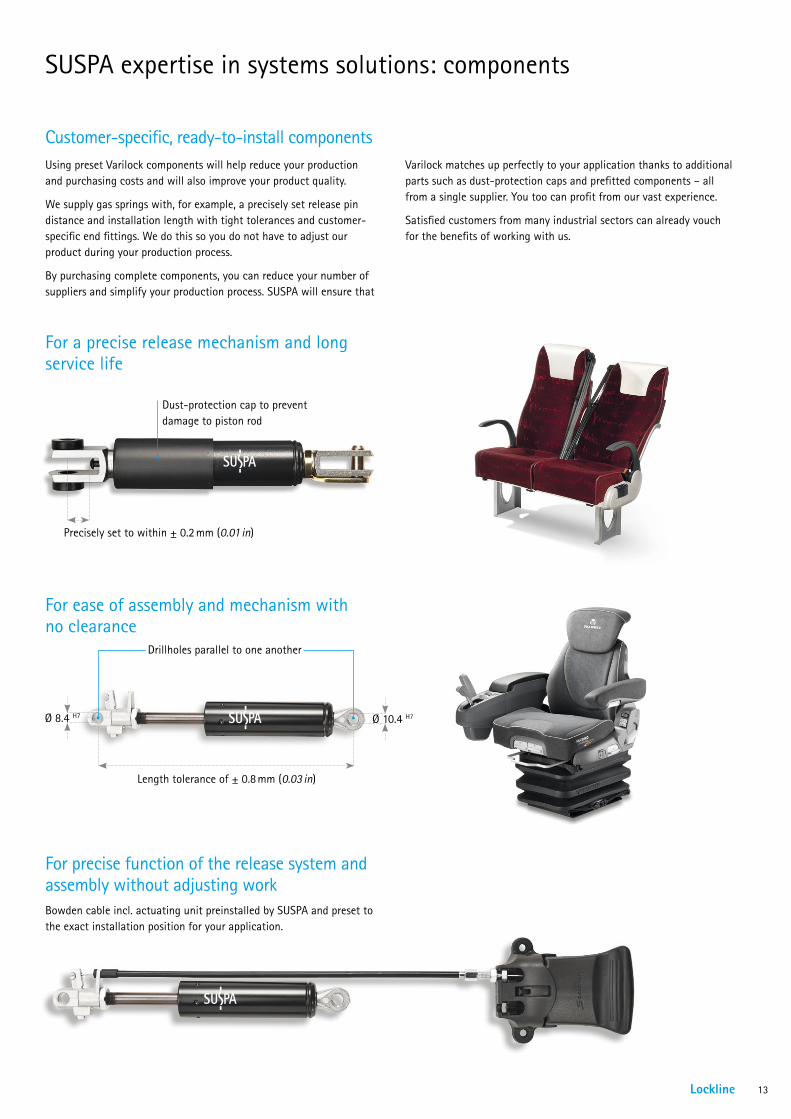
SUSPA expertise in systems solutions: components
Using preset Varilock components will help reduce your production and purchasing costs and will also improve your product quality.
We supply gas springs with, for example, a precisely set release pin distance and installation length with tight tolerances and customer-specific end fittings. We do this so you do not have to adjust our product during your production process.
By purchasing complete components, you can reduce your number of suppliers and simplify your production process. SUSPA will ensure that
Customer-specific, ready-to-install components
For precise function of the release system and assembly without adjusting workBowden cable incl. actuating unit preinstalled by SUSPA and preset to the exact installation position for your application.
For a precise release mechanism and long service life
Dust-protection cap to prevent damage to piston rod
Precisely set to within ± 0.2 mm (0.01 in)
For ease of assembly and mechanism with no clearance
Drillholes parallel to one another
Length tolerance of ± 0.8 mm (0.03 in)
Ø 10.4 H7Ø 8.4 H7
Varilock matches up perfectly to your application thanks to additional parts such as dust-protection caps and prefitted components – all from a single supplier. You too can profit from our vast experience.
Satisfied customers from many industrial sectors can already vouch for the benefits of working with us.
Lockline 13

SUSPA expertise in system solutions: VariStand
The VariStand table column is a professional, sophisticated, design- orientated solution for all table and cart applications. It is character-ized by its ease of use and plug & play assembly. VariStand offers high-quality and comfortable height adjustment.
The design-orientated table column
• Elegant design with round tubes
• Precise, quiet guide system
• Rigid or elastic locking in any position
• Constant force, independent of position
• Non-rotational column
• Large adjustment range despite short installation length
• Quick and easy to adjust
• Plug & Play assembly
• OverRide-function: tabletop can be lifted without activating the release (optional)
Highlights
Features ValuesDiameter [mm]/(inch) Ø 75 / Ø 70 (2.95 / 2.76)Stroke [mm]/(inch) max. 450 (17.7) (standards 415 / 225)Length compressed (Lcompr.) [mm]/(inch) stroke + 166 (6.5)
Length extended (Lextended) [mm]/(inch) Lcompr. + stroke, max. 1,065 (42.0)
Stroke force from 70 N (16 lbs) up to 400 N (90 lbs),according to weight of tabletop or application
Surface finishing chrome plated, powder-coated (RAL colors)Activation / release lever, cable releaseTabletop fitting flange adapter (with 12 drillholes, distance 32 mm, 1.26 in)Base fitting flange or tapered cone adapterNon-rotation function standardOverRide function optional
Features Ordering number
13652065 13652067 13652064 13652066Diameter [mm]/(inch) 75 / 70 (2.95 / 2.85)Stroke [mm]/(inch) 415 (16.3) 225 (8.9) 415 (16.3) 225 (2.95 / 2.85)Length compressed (Lcompr.) [mm]/(inch) 625 (24.6) 435 (17.1) 625 (24.6) 435 (17.1)
Length extended (Lextended) [mm]/(inch) 1,040 (40.9) 660 (26.0) 1,040 (40.9) 660 (26.0)
Stroke force [N]/(lbs) 120 (27.0)Surface finishing chrome chrome silver grey silver greyActivation / release Bowden wire release system L = 280 mm (11.0 in)Tabletop fitting flangeBase fitting flange with hole-pattern 3 x M6, Ø 58 mm (2.3 in)Non-rotation function standardOverRide function none
Trolleys, Carts Overbed tablesSpeaker‘s desk, Teacher´s desk
Side tables, Bistro tables
Applications 3 x 120°
58mm 3 x M6, thread depth:10 mm max.
M20, thread depth 25 mm max.
75 mm
mm 07
stro
ke C
L e
xten
ded
72 mm
14
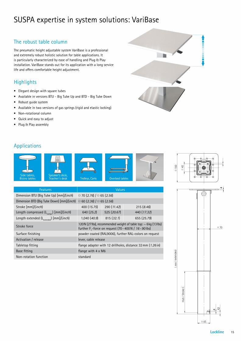
SUSPA expertise in system solutions: VariBase
The pneumatic height adjustable system VariBase is a professional and extremely robust holistic solution for table applications. It is particularly characterized by ease of handling and Plug & Play installation. VariBase stands out for its application with a long service life and offers comfortable height adjustment.
The robust table column
• Elegant design with square tubes
• Available in versions BTU - Big Tube Up and BTD - Big Tube Down
• Robust guide system
• Available in two versions of gas springs (rigid and elastic locking)
• Non-rotational column
• Quick and easy to adjust
• Plug & Play assembly
Highlights
Features Values
Dimension BTU (Big Tube Up) [mm]/(inch) □ 70 (2.76) / □ 65 (2.56)
Dimension BTD (Big Tube Down) [mm]/(inch) □ 60 (2.36) / □ 65 (2.56)
Stroke [mm]/(inch) 400 (15.75) 290 (11.42) 215 (8.46)Length compressed (Lcompr.) [mm]/(inch) 640 (25.2) 525 (20.67) 440 (17.32)
Length extended (Lextended) [mm]/(inch) 1,040 (40.9) 815 (32.1) 655 (25.79)
Stroke force120 N (27 lbs), recommended weight of table top: ~ 6 kg (13 lbs) further F1-force on request (70 - 400 N / 16 - 90 lbs)
Surface finishing powder coated (RAL9006), further RAL-colors on request
Activation / release lever, cable release
Tabletop fitting flange adapter with 12 drillholes, distance 32 mm (1.26 in)
Base fitting flange with 4 x M6
Non-rotation function standard
L au
s / e
xten
ded
Hub
/ St
roke
C
□ 70
□ 65
4
4 12
□ 42
□ 15
0
Trolleys, Carts Overbed tablesSpeaker‘s desk, Teacher´s desk
Side tables, Bistro tables
Applications
Lockline 15

Areas of application of lockable gas springs
• Steering column angle and length
• Covers for trunk lids and tonneau covers
• Multi-functional armrest for driver’s seat
• Equipment for mobile homes and recreational vehicles (backrest system, screen support, table, ...)
Automobile
Wheelchairs and caddies• Backrest, angle and height of seat, as well as leg support
Therapy beds and chairs• Adjusting the height and tilting of various elements
Hospital beds and tables• Adjusting the height and tilting of various bed parts
• Bed length
• Height adjustment for bedside tables, servers and keyboard supports
• Complete, ready-to-install column for table-height adjustment
Medi-Carts• Guide systems and complete columns for vertical adjustment
• Tilt adjustment
• Complete mechanical system with base, column and tabletop
Medical and rehab applicationsHome furniture• Positioning of chairs and of individual sections of beds
• Head support, backrest and leg support for armchairs
• Height adjustment for bedside tables/over-bed tables
• Complete, ready-to-install column for height adjustment of tables
Office furniture• Height of keyboard support
• Desk height
• Angle of backrest and seat surface for office chairs
• Sit-to-stand work surfaces and podiums
School furniture• Tabletop tilting
• Seat tilting
• Height of chairs and podiums for teachers and students
Chairs• Chair tilting
• Footrest height
Furniture
Busses and coaches• Backrest
• Leg support
Trains• Seat tilting
• Table height
Airplanes• Backrest
• Leg support
• Table height
Public transportation
16
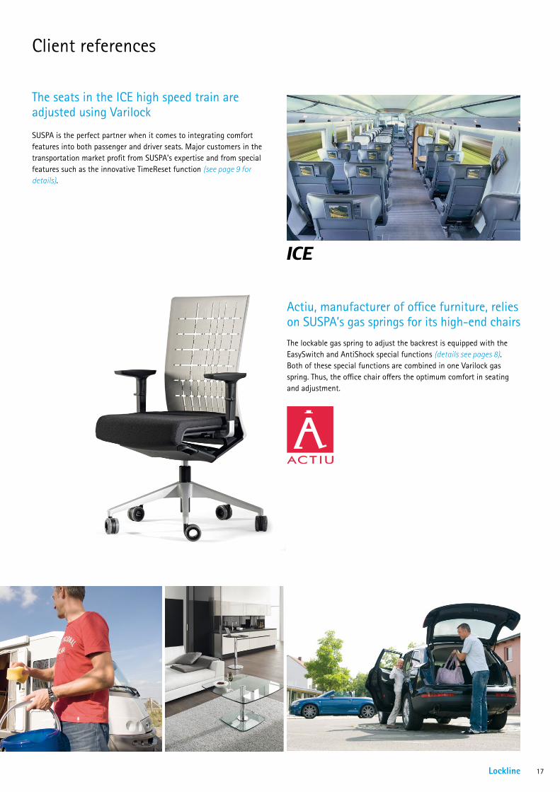
Client references
The lockable gas spring to adjust the backrest is equipped with the EasySwitch and AntiShock special functions (details see pages 8). Both of these special functions are combined in one Varilock gas spring. Thus, the office chair offers the optimum comfort in seating and adjustment.
SUSPA is the perfect partner when it comes to integrating comfort features into both passenger and driver seats. Major customers in the transportation market profit from SUSPA’s expertise and from special features such as the innovative TimeReset function (see page 9 for details).
Actiu, manufacturer of office furniture, relies on SUSPA’s gas springs for its high-end chairs
The seats in the ICE high speed train are adjusted using Varilock
Lockline 17
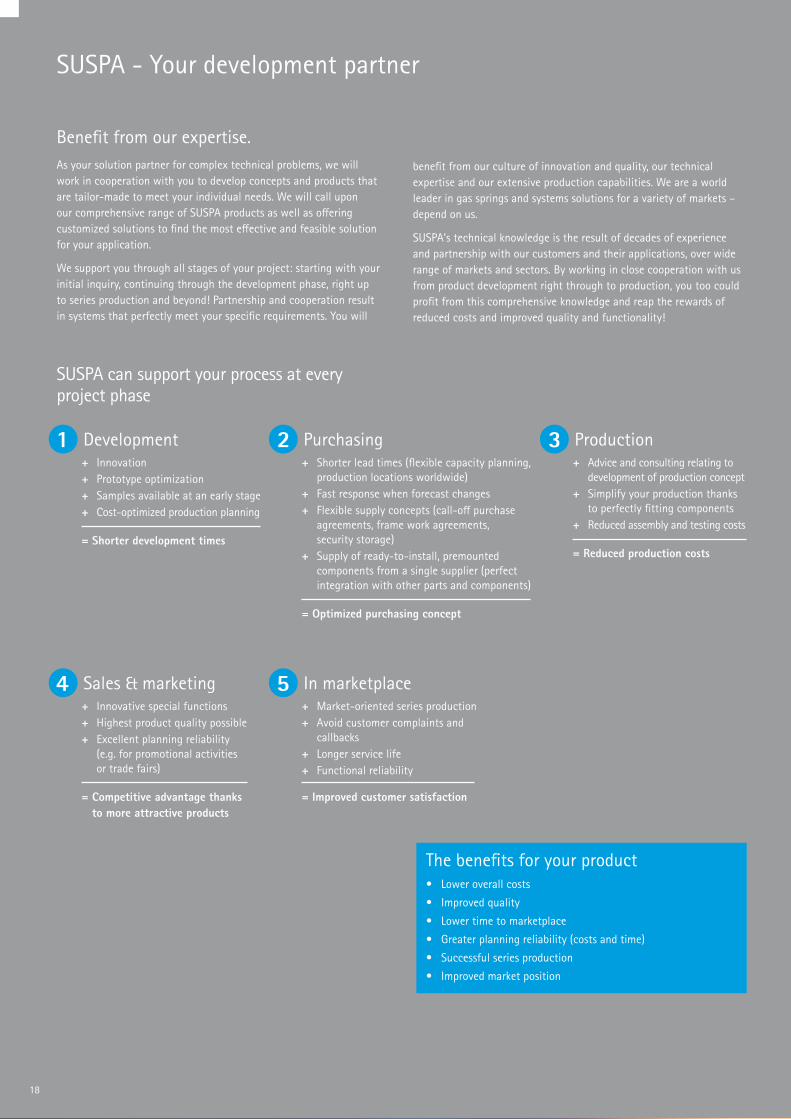
SUSPA - Your development partner
As your solution partner for complex technical problems, we will work in cooperation with you to develop concepts and products that are tailor-made to meet your individual needs. We will call upon our comprehensive range of SUSPA products as well as offering customized solutions to find the most effective and feasible solution for your application.
We support you through all stages of your project: starting with your initial inquiry, continuing through the development phase, right up to series production and beyond! Partnership and cooperation result in systems that perfectly meet your specific requirements. You will
Benefit from our expertise.
SUSPA can support your process at every project phase
benefit from our culture of innovation and quality, our technical expertise and our extensive production capabilities. We are a world leader in gas springs and systems solutions for a variety of markets – depend on us.
SUSPA’s technical knowledge is the result of decades of experience and partnership with our customers and their applications, over wide range of markets and sectors. By working in close cooperation with us from product development right through to production, you too could profit from this comprehensive knowledge and reap the rewards of reduced costs and improved quality and functionality!
2 + Shorter lead times (flexible capacity planning,
production locations worldwide) + Fast response when forecast changes + Flexible supply concepts (call-off purchase
agreements, frame work agreements, security storage)
+ Supply of ready-to-install, premounted components from a single supplier (perfect integration with other parts and components)
Purchasing
= Optimized purchasing concept
+ Innovation + Prototype optimization + Samples available at an early stage + Cost-optimized production planning
Development
= Shorter development times
1 + Advice and consulting relating to
development of production concept + Simplify your production thanks
to perfectly fitting components + Reduced assembly and testing costs
Production
= Reduced production costs
3
4 + Innovative special functions + Highest product quality possible + Excellent planning reliability
(e.g. for promotional activities or trade fairs)
Sales & marketing
= Competitive advantage thanks to more attractive products
+ Market-oriented series production + Avoid customer complaints and
callbacks + Longer service life + Functional reliability
In marketplace
= Improved customer satisfaction
5
• Lower overall costs
• Improved quality
• Lower time to marketplace
• Greater planning reliability (costs and time)
• Successful series production
• Improved market position
The benefits for your product
18

Storage
After longer periods of storage, a slight oil film may materialize at the piston rod side of the product. Such materialization is system-specific and has no impact on the function. Storage of the parts should be piston rod downward. Please activate the parts at least once after six months of storage.
Handling
SUSPA products may stand under high pressure. In order to avoid reduction of service life, safety and function, piston rods are not to be damaged, painted, or treated with aggressive materials. Keep away foil and paper packaging (statical charging). Radial stress effects, impact effects, any type of alteration or manipulation (f. e. opening), tensile load, heating, re-painting, removal of imprints, bulk handling, as well as extreme influence of wastewater, splash or salt water are not permissible. The outer tube is not to be deformed or damaged. Products that were modified or damaged in any kind must not to be put into operation and have to be exchanged.
Technical advice
Utilization
Your specific application is the basis for the technical design of SUSPA products. Please discuss your particular requirements with our application technicians in advance. Our products fulfill the specifications shown in SUSPA drawings. Unless otherwise specified, the products are to be used with the piston rods pointing down within a temperature range of –25°C up to +60°C (-13°F up to 140°F), in exceptional cases also within -30°C up to +80°C (-22°F up to 176°F). A detailed description of any specific gas spring can be found on its data sheet/drawing.
Lockline 19

09/2
015
www.suspa.com
SUSPA GmbHIndustriestr. 12-14 90518 Altdorf Germany
Telephone +49 9187 930 355 Fax +49 9187 930 311
E-mail [email protected] Internet www.suspa.com