lockin rob web - electronics research...
TRANSCRIPT
Lock-in amplifiers
A short tutorial by R. Scholten

Measuring something
Common task: measure light intensity, e.g. absorption spectrum
Need very low intensity to reduce broadening
Noise becomes a problem
Rb cell Photodiode
Laser
Rb spectrum
Frequency0
2
4
6
8

The principle
Fundamental law of communication theory:Wiener-Khinchin theorem
Reduction of noise imposed upon a useful signal with frequency f0, is
proportional to the square root of the bandwidth of a bandpass
filter, centre frequency f0

Noise
Typical photodetector noise spectrumPhotodector intensity
1.0 10 100 1kHz 10kHz 100kHzFrequency (Hz)
-150
-140
-130
-120
-110
-100
-90
On resonance
Off resonance
Dark noisePow
er s
pect
ral d
ensi
ty (d
B)
Better here!
Bad noise here…
90Hz Δfhere...
…and here!
dc measurements: • broad-spectrum (bad) • at low frequency (bad)
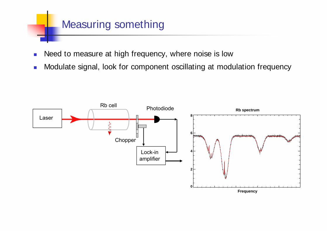
Measuring something
Need to measure at high frequency, where noise is low
Modulate signal, look for component oscillating at modulation frequency
Rb cell Photodiode
Laser
Chopper
Lock-inamplifier
Rb spectrum
Frequency0
2
4
6
8
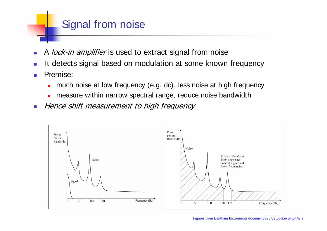
Signal from noise
A lock-in amplifier is used to extract signal from noiseIt detects signal based on modulation at some known frequencyPremise:
much noise at low frequency (e.g. dc), less noise at high frequencymeasure within narrow spectral range, reduce noise bandwidth
Hence shift measurement to high frequency
Figures from Bentham Instruments document 225.02 Lockin amplifiers
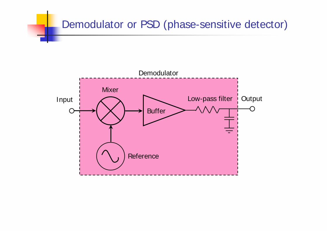
Demodulator or PSD (phase-sensitive detector)
Buffer
Reference
Demodulator
InputMixer
Low-pass filter Output

Mathematical description
Signal VS(t) varies relatively slowlye.g. absorption spectrum scan over 10 seconds
Modulate at relatively high frequency ω (e.g. chopper):
Reference (local oscillator) of fixed amplitude:
phase φ is variableoscillator frequency ω same as modulation frequency
Multiply modulated signal by REF :
Second term at high frequency (2ω)
Low-pass filter (cutoff ~ ω/2 or lower)
( ) ttVV S ωcossig =
( )φω += tV cosref
( ) ( )( ) ( ) ( )φωφ
φωω
++=
+=
ttVtV
tttVVV
SS
S
2coscos
coscos
21
21
refsig
( ) φcosfilter 21
refsig tVVV S=××
Note phase-sensitive detection!

Some details
Simple trig
( ) ( ) ( )( ) [ ]( )[ ]( ) ( )[ ]( )[ ]( ) ( )[ ]( ) ( ) ( ) ( )φωφωφ
φωφωφφωφωφφωφω
φωωφω
φωφωω
φωφωω
++++=
+−+=+−+=+−+=
+−=
+−=
+++=
ttnttVtVtttVtV
tttVtttV
ttttV
ttttV
ttntttVVV
SS
SS
S
S
S
S
S
cos)(2coscos...sin2sincos2coscos
...sin2sincos2coscos...sin2sincos2cos
...sinsincoscoscos
...sinsincoscoscos
cos)(coscos
21
21
21
21
21
21
21
21
2
sigref

Noise
Noise reduces with frequency (1/f noise is major problem)
Shift signal to higher frequency
Noise within given bandwidth reduces as we measure at higher frequency
Laser frequency noise
-100
-90
-80
-70
-60
-50
-40
1.0 10.0 100.0 1000.0 10000.0 100000.0
Frequency (Hz)
dbV/
sqrt
(Hz)
www.technion.ac.il/technion/chemistry/courses/w05/127421

With noise
Signal has noise:
Multiply reference by modulated signal:
Third term – noise – at frequency ωLow-pass filter, frequency less than ω/2, leaves signal componentsWe win twice:
less noise at ωreduce bandwidth
( ) )(cossig tnttVV S += ω
( ) ( ) ( )( ) ( ) ( ) ( )φωφωφ
φωφωω++++=
+++=ttnttVtV
ttntttVVV
SS
S
cos)(2coscoscos)(coscos
21
21
sigref

Using PSD oscillator to modulate
Buffer
Reference
Phase-sensitive detector
Signal
MixerLow-pass filter Output
Mod
Expe
rimen
t

External modulator: true “lock-in”
Buffer
PLL = phase-locked loop
Lock-in amplifier
Signal
MixerLow-pass filter Output
vcoExpe
rimen
t
Ref
Integrator
∫
Further details
True lock-in amp can work with external oscillator for Reference:Input reference from external experimentUse phase-locked-loop to generate stable local oscillator
Lock-in amp has variable post-multiplier (low-pass) filterTime constants: what time constant is appropriate?Shapes (6th, 12th, … order): which is best?
If input signal has harmonics (e.g. due to imperfect modulation) then will detect spurious signal
Use input filter to minimise
Dynamic reserve?

Other applications
Often use lockin to measure response function of actuator (or similar)Two-channel lockin – measure signal and phasePhase → resonances
0°Ref
Phase-sensitive detector
Signal
In-phase and quadrature mixers
ModActu
ator
(e.
g. p
iezo
)
90°
90°
0°

Experiments
Photodiode + LEDSRS FFT spectrum analyserOscilloscopeSwitch LED on/off, e.g. with hand to blockHP function generator to modulate LEDAnd/or chopperSRS lock-in amp

The other half of the story
Frequency modulation
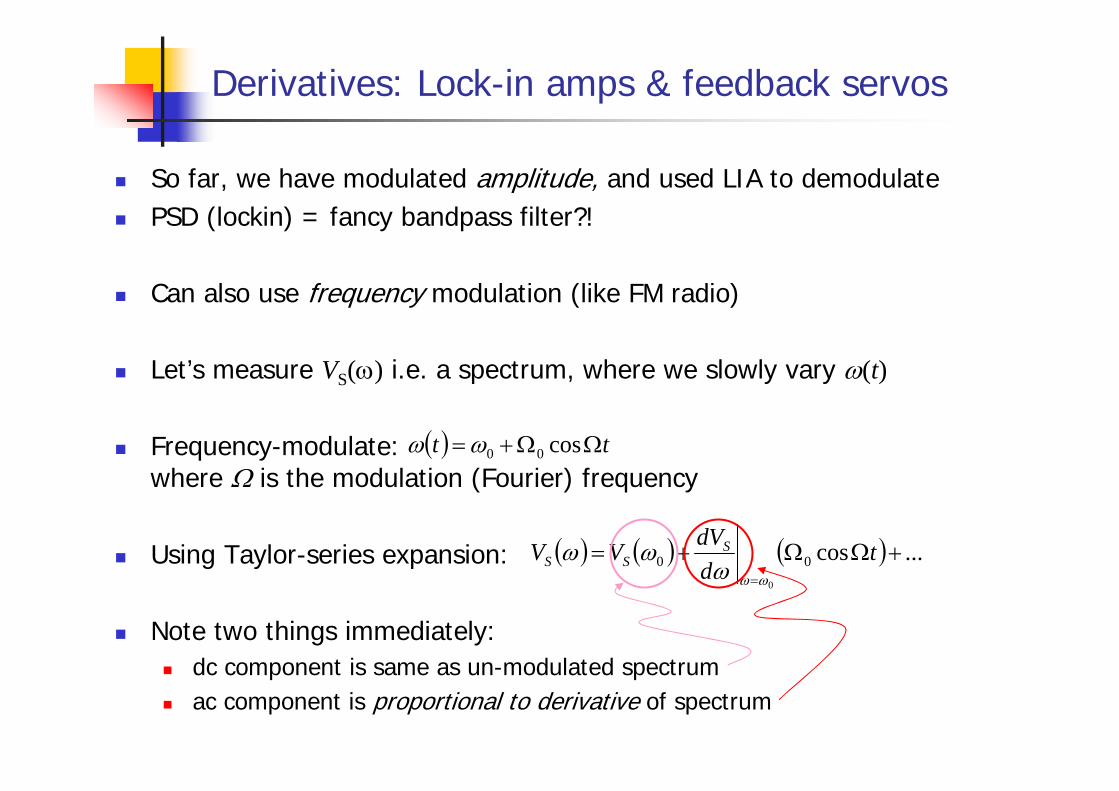
Derivatives: Lock-in amps & feedback servos
So far, we have modulated amplitude, and used LIA to demodulatePSD (lockin) = fancy bandpass filter?!
Can also use frequency modulation (like FM radio)
Let’s measure VS(ω) i.e. a spectrum, where we slowly vary ω(t)
Frequency-modulate: where Ω is the modulation (Fourier) frequency
Using Taylor-series expansion:
Note two things immediately:dc component is same as un-modulated spectrumac component is proportional to derivative of spectrum
( ) tt ΩΩ+= cos00ωω
( ) ( ) ( ) ...cos000
+ΩΩ+==
tddVVV S
SSωωω
ωω

Extract derivative with PSD/lock-in amp
We now multiply our signal by our reference, as before:
Note modulation at Ω, and fixed ω0 i.e. slowly varying laser frequency
Again: low-pass filter (cutoff ~ ω/2 or lower)
We have a measurement proportional to the derivativeMeasurement changes sign if slope changes sign: dispersionNote: modulation depth Ω0 must not be larger than peak in spectrum!Higher-order terms in Taylor expansion: can measure 2nd deriv, 3rd deriv, etc.
( ) ( )
( ) ( ) φω
φω
φ
φω
φ
cos2coscos
...
coscoscos
021
021
0refsig
ddVt
ddVtV
ttddVtVVV
SSS
SS
Ω++ΩΩ++Ω=
=
+ΩΩΩ++Ω=
( ) ( ) ...cos00sig0
+ΩΩ+==
tddVVV S
Sωωω
ω ( )φ+Ω= tV cosref
φω
cos021
refsig ddVVV SΩ≈
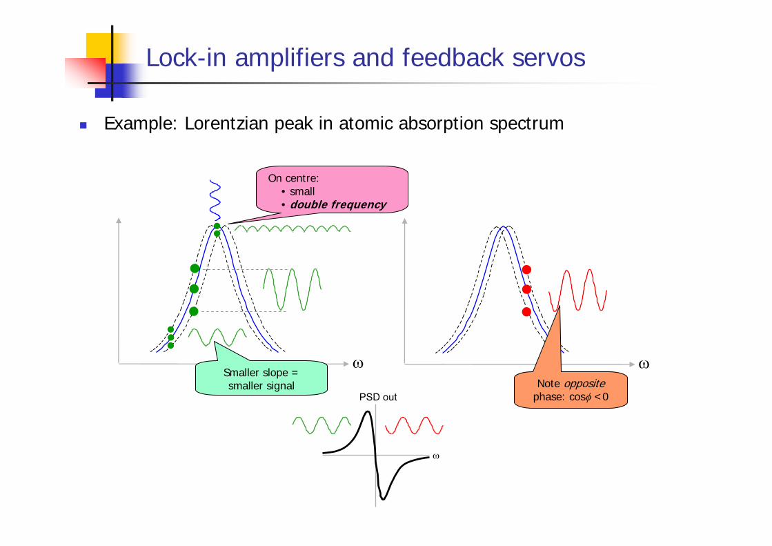
Lock-in amplifiers and feedback servos
Example: Lorentzian peak in atomic absorption spectrum
ω ωSmaller slope = smaller signal
On centre:• small• double frequency
Note opposite phase: cosφ <0
ω
PSD out

Modulated output from detector
Demodulated output from lock-in
Lock-in amps in servos
ω
t
t
t
t
t
ω
PSD out φω
cos021
refsig ddVVV SΩ≈

Yet other half of the story
Spread-spectrum

PRBS: Lock-in on steroids!
Lock-in uses small part of spectrumCan use broad spectrum and still separate signal from noisePseudo-random bit sequence
Spread-spectrum communicationscomputer 802.11 wireless, etc.CDMA telephonesModems
Security/encryptionAcoustics

Spread-spectrum modulation
• all frequencies present simultaneously in modulation function
SPREAD-SPECTRUM MODULATION
• phases adjusted so that components add in quadrature
• truly random phases cause excursions out of range⇒ use pseudo-random functions
20 frequenciesrandom phases
http://www.chm.bris.ac.uk/pt/mcinet/sum_schl_02_docs/tof.ppt
http://www.chm.bris.ac.uk/pt/mcinet/sum_schl_02_docs/tof.ppt

Spread-spectrum history
http://www.ncafe.com/chris/pat2/index.html
• Hedy Lamarr (1913-2000), composer George Antheil (1900-1959) patented submarine communication device
• Synchronized frequency hopping to evade jamming
• Original mechanical action based upon pianolas
• Used today in GPS, cellphones, digital radio
http://www.chm.bris.ac.uk/pt/mcinet/sum_schl_02_docs/tof.ppt
Also famous as first nude in cinema-release movie!

Binary pseudo-random sequences
1 2 3 4 5 6 7 8
D
Clock
SHIFT REGISTER
time
clock input
output• sequence length bits
with n bit shift register12 −n
× =
AUTOCORRELATION
( )121 −± n
1
http://www.chm.bris.ac.uk/pt/mcinet/sum_schl_02_docs/tof.ppt

PRBS: Lock-in on steroids!
Generate signal in pseudo-random bit sequence, for example:6-bit (64-bits long)
011010101111110000010000110001010011110100011100100101101110110
8-bit (256 bits long):000110110111001000101101100101100111011010111010100110111100111110101100010100001111010011110001000111010001001100100111001101010110100101011111101110111110000011001100001000010101010001100011111111001010010000000101111011000000111000110100000100100101110
Record signalMultiply by PRBS (auto-correlate)Very much like a lock-in! But uses broad spectrum
Reference
Computer
Signal
Multiplier
Output
Mod
Expe
rimen
t
Record/average
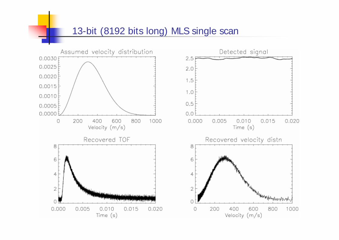
13-bit (8192 bits long) MLS single scan