locke suspension insulators
TRANSCRIPT

BALTIMORE, MARYLAND
CA
TA
LO
G N
UM
BE
R081
LOCKE SUSPENSIONLOCKE SUSPENSIONINSULATORSINSULATORS


1
GUIDE TO SELECTION OF LOCKE SUSPENSION INSULATORS
B A L L & S O C K E T T Y P E C L E V I S T Y P E M&E Without Zinc Sleeve With Zinc Sleeve Shed Diameter x Spacing Without Zinc Sleeve Shed Diameter x Spacing
Strength (ANSI Class) (ANSI Class) (Leakage Distance) (ANSI Class) (Leakage Distance)
20K 20S840 (52-3) 20S195 (52-3) 10” x 5 3/4”(12 5/8”) 20S580 (52-4) 10” x 5 3/4”(12 5/8”)
30K 30S255 (52-5) 30S295 (52-5) 10” x 5 3/4” (12 5/8”) 30S257 (52-6) 10” x 5 3/4” (12 5/8”)
40K 40S360 (52-8) 40S370 (52-8) 10” x 5 3/4” (12 13/16”) 40S290 (52-10) 10” x 6 1/2” (12 13/16”)
50K --- CA589MZ* (52-11) 11” x 6 1/8” (15 15/16”) CA589Q* (52-12) 11” x 7” (15 15/16”)
*We offer 50,000 lb M&E insulators under NGK part numbers. Please reference NGK catalog No. 14C.
L O C K E S U S P E N S I O N I N S U L A T O R SL O C K E S U S P E N S I O N I N S U L A T O R S

LOCKE INSULATORS, INC. SUSPENSION INSULATORS
Locke suspension insulators are designed and manu-
factured to give unparalleled performance and reliability.
Silent testimony to this fact is the continuing function of
the millions of units already in service. Although shapes
and appearances seem unchanging, today’s insulators
provide even greater benefi ts and reliability than in the
past. Special features and performance capabilities have
been added which signifi cantly assist the transmission
line designer.
LOCKE SUSPENSION INSULATORS
CONSTRUCTION DETAILS
Today’s insulators
provide even greater
benefi ts and reliability
than in the past.

3
1. CONNECTIONS
Insulators are furnished with either ball-and-socket or
clevis-eye confi gurations. The ability for either style to
be connected with other similar insulators is assured by
conformance to ANSI standards. Routine checks are
made with gages.
2. COTTER KEYS
Positive locking of both types is attained by using a
humped-type cotter key to prevent unintentional uncou-
pling during service or handling.
The ball-and-socket design has enjoyed a greater popu-
larity over the years because of the overall fl exibility and
the lack of loose parts. The self-contained split cotter
key, by virtue of its hump, can be maintained in either
the locked or unlocked position.
3. CAPS & PINS
Caps are manufactured of malleable iron or ductile iron.
Pins are forged steel.
Caps and pins are galvanized per ASTM A153.
A permanently fl exible coating on the inside of the cap
and on the pin protects the cap and pin from chemical
attack by the cement. The coating also provides more
uniform distribution of working stresses in the insulator
components.
4. PORCELAIN SHELLS
Proven manufacturing techniques provide the fi nest qual-
ity porcelain to ensure uniformly high mechanical and
electrical strength.
Each class of insulator has been designed with the
unique confi gurations required to develop the required
electrical and mechanical performance.
All exposed surfaces are glazed to provide a smooth
hard fi nish, which is easily cleaned of contaminants, and
which signifi cantly enhances the mechanical strength.
Glaze-bonded sand surfaces on the porcelain provide
reliable gripping areas for the cement to develop the full
strength of the insulator.
5. ASSEMBLY & TEST
Assembly of hardware and porcelain is made with
Alumina cement, which has superior characteristics over
the Portland cement which is normally used. The cement
is steam-cured under controlled conditions to achieve
optimum physical properties.
Each insulator is mechanically proof-tested at 50% of its
M&E rating and is electrically tested prior to shipment.
6. MARKING & COLOR
Each porcelain shell is permanently marked to show the
manufacturer name, year of manufacture, M&E Strength
and Proof-Test Value which has been applied to the
insulator.
Insulators are available in the following glaze colors: light
gray, dark gray, royal blue, and brown.

4
LONG TERM STRENGTH
Experience shows that Locke suspension insulators
maintain their mechanical strength over long periods of
time without deterioration. This performance results
from using properly engineered materials, good design,
and modern manufacturing equipment and technology.
We think that it is important to be able to substantiate
that our insulators do indeed have long-term strength.
We have established an in-house specifi cation to use the
IEC Publication 60575, “Thermal-Mechanical Perfor-
mance Test and Mechanical Performance Test on String
Insulator Units”, as a design test for all Locke suspen-
sion insulators. This test consists of simultaneously
applying a mechanical cyclical load and a thermal cyclical
environment to the insulators. After four cycles, the
insulators are subjected to an M&E test. We feel that
the M&E results obtained after cyclical stressing of the
insulators should be substantially the same as the M&E
results obtained without cyclical testing.
A substantial amount of data obtained on a variety of
designs by many manufacturers shows a remarkable cor-
relation with extended fi eld performance Designs that
perform well on this test have performed very well in
service whereas those designs that perform poorly have
demonstrated generally unsatisfactory fi eld performance.
Contact your local sales representative for design reports
covering Long-Term Tests.
LOKGARD® SLEEVE
All Locke ball and socket suspension insulators can be
equipped with Lokgard sleeves where pin corrosion has
been or is expected to be a problem. Serious pin
corrosion can result from electrolytic action with the
most severe activity apparently related to areas having
high levels of contamination. Corrosion can take place
totally outside of the cement which results solely in loss
of pin cross-section and hence mechanical strength.
Or it can take place inside the cement causing bursting
pressure to the porcelain shell with subsequent
catastrophic electrical and mechanical failure.
The Lokgard sleeve is high purity zinc that is cast on to
the insulator pin prior to assembly. It too will corrode
in service at approximately the same rate as the steel
in the pin, but until the zinc is consumed, no corrosion
of the steel can occur. Additionally, the zinc oxidizes
without residue, and cannot build up the larger expansion
volume in the manner of rusted steel. Therefore, it is
impossible for a Lokgard protected insulator porcelain
shell to be subjected to corrosion-caused hoop
stress damage.

20,000 lb. M & E
5
Catalog Number 20S840 20S580Cat. No. w/LOKGARD Sleeve 20S195 -ANSI Class 52-3 52-4
M&E Rating, lb. 20,000 20,000Leakage Distance in. 12 5/8 12 5/8Dry Arcing Distance, in. 7 9/16 7 9/16Mechanical Impact Strength, in.-lb. 100 100Tension Proof, lb. 10,000 10,000
Low Frequency Flashover Dry, kV 80 80
Wet, kV 50 50
Critical Impulse Flashover Pos., kV 125 125
Neg., kV 130 130Low Frequency Puncture, kV 110 110
“Test Voltage,
10 10 RMS to Ground, kV” “Max. RIV
50 50 at 1000 kHz, uV “
Net Weight Each, lb. 10.6 12.1Standard Package Quantity 6 6Packed Weight, lb. 78 82
“Radio infl uenceVoltage Data”
CHARACTERISTICS
20S840ANSI CLASS 52-3
20S580ANSI CLASS 52-4

30,000 lb. M & E
6
Catalog Number 30S255 30S257Cat. No. w/LOKGARD Sleeve 30S295 -ANSI Class 52-5 52-6
M&E Rating, lb. 30,000 30,000Leakage Distance in. 12 5/8 12 5/8Dry Arcing Distance, in. 7 9/16 7 9/16Mechanical Impact Strength, in.-lb. 100 100Tension Proof, lb. 15,000 15,000
Low Frequency Flashover Dry, kV 80 80
Wet, kV 50 50
Critical Impulse Flashover Pos., kV 125 125
Neg., kV 130 130Low Frequency Puncture, kV 110 110
“Test Voltage,
10 10 RMS to Ground, kV” “Max. RIV
50 50 at 1000 kHz, uV “
Net Weight Each, lb. 11.7 12.1Standard Package Quantity 6 6Packed Weight, lb. 84 82
“Radio infl uenceVoltage Data”
CHARACTERISTICS
30S255ANSI CLASS 52-5
30S257ANSI CLASS 52-6

40,000 lb. M & E
7
Catalog Number 40S360 40S290Cat. No. w/LOKGARD Sleeve 40S370 -ANSI Class 52-8 52-10
M&E Rating, lb. 40,000 40,000Leakage Distance in. 12 13/16 12 13/16Dry Arcing Distance, in. 7 11/16 7 11/16Mechanical Impact Strength, in.-lb. 100 100Tension Proof, lb. 20,000 20,000
Low Frequency Flashover Dry, kV 80 80
Wet, kV 50 50
Critical Impulse Flashover Pos., kV 125 125
Neg., kV 130 130Low Frequency Puncture, kV 110 110
“Test Voltage,
10 10 RMS to Ground, kV” “Max. RIV
50 50 at 1000 kHz, uV “
Net Weight Each, lb. 14.7 15.4Standard Package Quantity 6 6Packed Weight, lb. 97 102
“Radio infl uenceVoltage Data”
CHARACTERISTICS
40S360ANSI CLASS 52-8
40S290ANSI CLASS 52-10
8
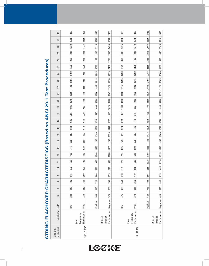
ST
RIN
G F
LA
SH
OV
ER
CH
AR
AC
TE
RIS
TIC
S (
Ba
se
d o
n A
NS
I 2
9-1
Te
st P
ro
ce
du
re
s)
6
7
8
9
10
11
12
13
14
15
16
17
18
19
20
21
22
23
24
25
26
27
28
29
30
Dry
38
0
440
49
5
545
60
0
650
70
0
745
79
5
840
88
0
925
96
5
1005
10
45
1080
11
20
1155
11
90
1220
12
55
1285
13
20
1350
13
80
Wet
24
0
280
32
0
360
40
0
440
48
0
520
56
0
600
64
0
680
72
0
760
80
5
845
88
5
925
96
5
1005
10
45
1085
11
25
1165
12
05
Posi
tive
56
0
640
72
0
800
88
0
960
10
40
1120
12
00
1280
13
60
1440
15
20
1600
16
80
1760
18
35
1915
19
95
2075
21
55
2235
23
15
2395
24
75
Neg
ativ
e 5
75
660
74
5
825
91
0
995
10
80
1165
12
50
1335
14
20
1505
15
90
1675
17
60
1845
19
25
2010
20
95
2180
22
65
2350
24
35
2520
26
05
Dry
42
5
490
55
0
610
66
5
720
77
5
825
87
5
920
97
0
1015
10
55
1100
11
40
1180
12
15
1255
12
90
1325
13
60
1395
14
25
1460
14
90
Wet
27
0
315
36
5
410
45
5
500
54
5
590
63
5
680
72
5
770
81
5
860
90
5
950
10
00
1045
10
90
1135
11
80
1225
12
70
1315
13
60
Posi
tive
62
5
715
80
5
895
98
5
1075
11
65
1255
13
45
1435
15
25
1615
17
05
1795
18
85
1975
20
65
2155
22
45
2335
24
25
2515
26
05
2695
27
85
Neg
ativ
e 6
40
735
83
0
925
10
20
1120
12
15
1310
14
05
1500
15
95
1690
17
85
1885
19
80
2075
21
70
2265
23
60
2455
25
50
2650
27
45
2840
29
35
Low
Fr
eque
ncy
Flas
hove
r kv
Criti
cal
Impu
lse
Flas
hove
r kv
Low
Fr
eque
ncy
Flas
hove
r kv
Criti
cal
Impu
lse
Flas
hove
r kv
10”
x 5
3/4”
10”
x 6
1/2”
Disc
Dia
. x
Spac
ing
N
umbe
r of U
nits


BALTIMORE, MARYLAND
S A L E S O F F I C E S
NGK-LOCKE INC. (BALTIMORE OFFICE)
2525 Insulator DriveBaltimore, Maryland 21230, U.S.A.
Tel: +1(410) 347-1700Fax: +1(410)347-1724
Email: [email protected]
NGK-LOCKE INC. (ATLANTA OFFICE)
1880 West Oak ParkwaySuite 104
Marietta, Georgia 30062, U.S.A.Tel: +1(404) 659-3153Fax: +1(678) 303-1374
Email: [email protected]
NGK-LOCKE INC. (DALLAS OFFICE)
1452 Hughes RoadSuite 200
Grapevine, Texas 76051, U.S.A.Tel:+1(817) 410-5789 Fax:+1(817) 796-2290
Email: [email protected]
NGK-LOCKE INC. (LOS ANGELES OFFICE)
21250 Hawthorne Blvd., Suite 500Torrance, California 90503, U.S.A.
Tel: +1(310) 316-3323 Fax: +1(310)316-3944
Email: [email protected]
NGK INSULATORS OF CANADA, LTD.
(TORONTO OFFICE)
2700 Matheson Blvd. East, Suite 700East Tower, Mississauga, Ontario L4W 4V9, Canada
Tel: +1(905) 602-1266Fax: +1(905)238-8247
Email: [email protected]
NGK INSULATORS OF CANADA, LTD.
(MONTREAL OFFICE)
1501, Avenue McGill College, Bureau 515Montreal (Quebec) H3A 3M8, Canada
Tel: +1(514) 281-8488 Fax: +1(514)281-8596
Email: [email protected]