lockdog contingency tool 20tpublications.lib.chalmers.se/records/fulltext/158945.pdf · lockdog...
TRANSCRIPT

LockDog Contingency Tool 20T For HCS 12” Installation Tool
Degree project in the Bachelor of Science in Engineering Programme
Mechanical Engineering
HOGLID, ERIK
PETTERSSON, JONAS
Department of Materials and Manufacturing Technology
Division of Advanced Non-destructive Testing
CHALMERS UNIVERSITY OF TECHNOLOGY
Gothenburg, Sweden, 2012 Examiner: Gert Persson Report No. 73/2012

I
PREFACE This degree project has been done at Aker Solution in Gothenburg spring 2012 as a part of the
mechanical engineer program with specialization mechanical design, 180HP at Chalmers
University of Technology.
We want to thank Martin Stegberg, our mentor and all engineers at the Tie-in Department at
Aker Solutions for all the help we got. We also want to thank our mentor Gert Persson at
Department of Material and Manufacturing technology at Chalmers University of
Technology.
A special thanks goes to Gustaf Wallerstedt, Martin Stegberg and Runar Helgesen for giving
us the opportunity to carry out the project at Aker Solution and helping us with the equipment
and work-area at your company.
Ort: Göteborg Datum: 13-06-2012
Jonas Pettersson Erik Hoglid

II
SUMMARY Aker Solutions is a global leading company in the offshore industry with its headquarters in
Oslo, Norway. Aker Solution has recently opened its first office in Sweden, Gothenburg.
When a subsea installation with oil- and gas pipes is done, an installation tool is used. The
installation tool is connected to an interface/connecting system with two bolts. The
installation tool together with the pipe will thereafter be lowered down to the subsea plant
where it will be connected to the structure.
When the pipe and the pipe interface have landed at the subsea installation platform, the
installation tool is removed. This is done by moving two levers connected to each bolt,
unlocking the installation tool. This is carried out by an underwater robot (ROV-Remote
Operated Vehicle).
These ROV are used in the entire installation process and will do all the work at the subsea
plant. For tasks it can’t do by its two arms it uses tools.
Due to the pipe flexibility, an angle between the installation tool and the subsea structure can
occur. Tensions will then arise between the bolt and the pipe connection system. In some
cases tension gets so high that the ROV won’t be able to unlock the two bolts and disconnect
the installation tool, making further installation impossible.
Aker Solution gave us the assignment to develop a contingency tool. This tool will be used
when the ROV fails to disconnect the installation tool.
The project started with collecting information about ROV (underwater robots) and the steps
in the installations process. Then 16 different concepts of possible contingency tools were
developed. A Pugh matrix was evaluated and together with Martin Stegberg at Aker Solutions
one final concept was chosen that had all requirements to meet the design criteria.
Further development of the final concept was made with help of the CAD-program
SolidWorks. A complete 3D- prototype was developed. FEM-analyses, drawings for
manufacturing and operation maintenance manual were also made.
All documents and drawings for manufacturing have been handled over to Aker Solutions.

III
SAMMANFATTNING Aker Solutions är ett världsledande företag inom offshorebranschen med sitt huvudkontor i
Oslo, Norge. Aker Solutions har kontor i Göteborg där drivs bland annat projekt inom
rörinstallationer för undervattens plattformar.
Vid installation av en olje/gasledning på havsbottnen används ett installationsverktyg för att
sänka ner ledningen så dess ände hamnar på önskad plats. Kopplingen mellan
installationsverktyget och ändröret är konstruerat med två bultar som är kopplade till varsin
hävarm, dessa låser ändröret till installationsverktyget. Sammankoppling och frånkoppling av
installationsverktyget från ändröret utförs av undervattensrobotar. Undervattensrobotarna
används också för att sammankoppla ledningens ändrör till övrig struktur på botten. För det
sistnämnda använder robotarna verktyg.
Eftersom ledningen är flexibel kan det uppkomma en vinkel mellan installationsverktyget och
övrig struktur vid installationen. Om vinkeln blir stor uppkommer spänningar mellan bultarna
och ändröret. I värsta fall kan vinkeln och därmed spänningen bli så stor att
undervattensroboten inte längre klarar att dra ur bultarna och därmed koppla loss
installationsverktyget. Det scenariot måste till varje pris undvikas.
Därför har Aker Solutions, som utvecklar och monterar dessa ledningar, givit oss i uppgift att
utveckla ett extra verktyg som undervattensrobotarna kan använda i de fall då bultarna i
installationsverktyget inte går att lossa.
Första delen av projektet bestod i att samla information om undervattensroboten och hur
installationsprocessen går till. I andra delen av projektet skissades det på olika lösningar på
extra verktyget. Detta resulterade i 16 olika koncept, dessa utvärderades med hjälp av en
utvärderingsmatris samt med Martin Stegberg på Aker Solutions. Till slut valdes ett koncept
som uppfyllde de kraven som var satta för extraverktyget och som var tillförlitligast.
Vidareutveckling av konceptet gjordes med hjälp av CAD-programmet SolidWorks. En
fullständig 3D-prototyp modellerades fram. Denna användes sedan för FEM-analys,
ritningsunderlag för tillverkning samt en operationsmanual som beskriver hur extraverktyget
fungerar och skall användas.
Alla dokument och ritningsunderlag har lämnats över till Aker Solutions. Ett beslut om
verktyget skall produceras ligger nu hos Aker Solution.

IV
TABLE OF CONTENTS Preface ......................................................................................................................................... I
Summary ................................................................................................................................... II
Sammanfattning ....................................................................................................................... III
Table of contents ...................................................................................................................... IV
Designations ............................................................................................................................... 1
1 Introduction ......................................................................................................................... 2
1.1 Background ................................................................................................................................. 2
1.2 Purpose ....................................................................................................................................... 2
1.3 Delimitations .............................................................................................................................. 3
1.4 Precision of question formulation .............................................................................................. 3
2 Theoretical Frame of Referance .......................................................................................... 4
2.1 ROV ............................................................................................................................................. 4
2.2 ROV tools .................................................................................................................................... 5
2.3 HCS ............................................................................................................................................. 5
2.4 Installation tool .......................................................................................................................... 6
2.5 Installation process .................................................................................................................... 7
2.6 CAD/FEM .................................................................................................................................. 10
2.7 Pugh-matrix .............................................................................................................................. 11
3 Method .............................................................................................................................. 12
4 Design Criteria .................................................................................................................. 13
5 Design Basis ...................................................................................................................... 14
6 Concept ............................................................................................................................. 15
6.1 Concept phase 1 ....................................................................................................................... 15
6.2 First selection process .............................................................................................................. 22
6.3 Concept phase 2 ....................................................................................................................... 25
6.4 Second selection process ......................................................................................................... 31
7 Further development of concept ....................................................................................... 32
8 The Final Design ............................................................................................................... 37
8.1 Design Specifications ................................................................................................................ 37
8.2 Assembly and parts .................................................................................................................. 38
8.3 FEM ........................................................................................................................................... 46
8.4 Drawings ................................................................................................................................... 47
8.5 Hydraulic schedule ................................................................................................................... 48
V
8.6 Clearance .................................................................................................................................. 49
9 CalculAtions ..................................................................................................................... 50
9.1 Piston ........................................................................................................................................ 50
9.2 Cylinder..................................................................................................................................... 51
9.3 Shear stress analysis for the lock pin ....................................................................................... 52
10 Conclusions .................................................................................................................. 53
11 Discussion and reflection ............................................................................................. 54
References ................................................................................................................................ 55
Appendix A Pugh-Matrix
Appendix B Concepts
Appendix C Drawings for Maufaturing
Appendix D OMM

1
DESIGNATIONS HCS-Horizontal Connection System. A horizontal connection system for subsea sites that
connects cables and pipes to subsea sites.
ROV-Remote Operated Vehicle. A submarine which can be driven remotely from a ship.
FEM- Finite element method. FEM is used to do studies of the material and simulate stresses
that occur at different kind of loads.
CAD-Computer-Aided Design. A technique to draw 3D-models.
SolidWorks-CAD program. A program to make 3D-models.
UTH-Umbilical Termination Head. A control box that together with an umbilical cable can
control subsea sites.
IT- (first end) Installation tool. A tool which is used to lower and install cables.
CT-Contingency tool. A tool which is used when a normal procedure not going as planned.
LDCT-LockDog contingency tool. Name of the final concept.
OMM-Operation and Maintenance Manual. A guide for ROV operators and maintenance for
a product.
Envelope-Dimension requirements.
Weight in Water- Is the weight for an object minus waters lifting capacity.
Actual force F in water will be:
Gravity force Mg
Waters liftning force L
2
1 INTRODUCTION
1.1 Background HCS system is a subsea installation system to connect different platforms with each other.
Aker Solution has a problem with the installation process for HCS, first end installation tool.
The problem is when the first end installation tool is going to disconnect with the HCS. Two
lock pins who keep the installation tool connected to the HCS have had a tendency in some
circumstances to wedge themselves. Demands from Aker Solutions customers are that it
needs to be a total safety system with an emergency solution to lose the lock pins if they get
wedge.
1.2 Purpose The purpose is to develop a contingency tool for the HCS installation process.
Develop a contingency tool with a 3D-module, drawings for manufacturing and an OMM.

3
1.3 Delimitations
Only HCS 12" with umbilical cable system will be handled.
Only the release of 1:st end installation tool will be handled, calculated and designed.
Minor analytical calculations and FEM-analyses are done in SolidWorks.
No new 1:st end installation tool are developed.
No economics consideration is made.
1.4 Precision of question formulation
What is the installation tool release problem for ROV today?
Is it possible to use an existing ROV tool as a contingency tool?
Is it possible to modify the installation tool for an interface to connect a contingency
tool?
Is it possible to design a contingency tool which is reliable?

4
2 THEORETICAL FRAME OF REFERANCE This chapter, information about the main parts in an HCS installation process, also
information about programs and eliminations methods.
2.1 ROV ROV is a vehicle used for jobs under water; usually at places there a diver can’t work due to
the extreme conditions. ROV stands for Remote Operated Vehicle and as the name describes
you can drive/fly it from a distance, normally from a ship.
There are two types of ROV, one is for exploring, this is light, small and don’t have so many
functions as an installation ROV. That is because it needs to get in small places and if it hits
something it will not destroy anything. ROV use several propellers and floating tanks working
together to control it and steer it to the place you want it.
An installation ROV, like the Triton XLX 150 on the other hand has lots of functions. It has
hydraulic pressure and two arms. One of the arms is 5- articulated and used to hold on to stuff
and lift heavy equipment and materials. The other arm which is a 7- articulated is used to do
more precision operations.
Aker Solution is using ROV for all their install operations under water. Depth down to 3000m
makes it impossible for divers to work and therefor an ROV is used.
Aker Solution use ROV for tasks like guiding equipment down to the bottom, change seals
and install new pipes, an example is a HCS installation.
If the ROV doesn’t manage to do certain operation with its both arms it can use extra tools.
All tools are made to work under water and can be plugged in with the ROV
hydraulic/electric systems.
Figure 2.1-ROV-Triton XLX 150
Table 2.1-ROV parts
Number Description
1 7- articulated arm
2 5- articulated arm
2
1

5
2.2 ROV tools
Standard tool
Subsea installations are mainly done by the ROVs seven articulated arm. In some cases the
ROV use tools to carry out certain operations. All ROV-tools are collected in a bag that is
submerged together with ROV from the boat. In Table 2.2 is some ROV tools shown.
Table 2.2-ROV tools
Torque tool Hydraulic impact
wrench
Hydraulic grinder Bolt puller
Contingency tool
Contingency tool are often special made for contingency procedures, therefor only designed
to just fulfill a specific task. If something happen with the normal installation a back-up tool
(Contingency tool) are available to solve the problem.
2.3 HCS
This chapter will give some information about all the main part used in a HCS.
Figure 2.2-HCS with a umbinical control unit
Table 2.3-HCS-main parts
Number Description
1 Umbilical control unit (doesn’t exist if an oil or gas cable is used)
2 Cable
3 HCS part which is connected to a cable
4 HCS manifold

6
2.4 Installation tool
An installation tool (Figure 2.3) is used to immersing the cable to HCS manifold. Steel wires
from the boat are used to lower the IT together with the cable. Aker Solutions have used two
different connecting systems to connect and disconnect the installation tool from the HCS.
Figure 2.3-Installation tool
Table 2.4-Parts in the Installation tool
Number Description
1 Steel wires
2 Lever or Screw bolt system
3 Guide structure
2
3
1

7
2.5 Installation process
To connect umbilical cables under water a HCS connecting system are used. An umbilical
cable is unwound from the boat together with the installation tool. Under the whole
installation process an ROV is used to control the installation. When the IT and umbilical
cable has landed at the connecting site. ROV release the IT. When the work is completed the
IT will be brought back up to the ship. (Figure 2.4)
Figure 2.4-Installation process
Table 2.5-HCS with a IT
Number Description
1 Installation tool
2 Umbilical control box.
3 Pipe
4 One part of the HCS, which is lower down with the IT
5 The other part of the HCS which is mounted on some type of structure.
5
4
2
1
3

8
Screw bolt system
Under the installation bolted joints are used to connect the installation tool with HCS, see
Figure 2.5. HCS and IT is connected to each other through two bolts which are screwed into
two holes on the HCS. Due to the nature of the flexible cables, particularly when umbilical
cables are used, stresses can occur between HCS and installations tool. Force and shear stress
spreads to the two bolts and when the ROV try to unscrew the two bolts friction between the
joint prevent the ROV to unscrew them. Another problem with this system is that the threads
can easily be damaged and the blister wears out. This system is still relevant as a locking
solution if a CT is developed which can bring the bolt out if it get wedge. But at the moment it
is replaced to a lever system because of the systems unreliability.
Figure 2.5-Screw bolt
Table 2.6-Parts, Screw bolt
Number Description
1 Bolt with threads
2 ROV-Handle
3 Outer structure with is mounted on the IT. See Figure 2.3 number 1.
2
1
3

9
Lever system
This is a new system replacing the screw bolt system. An arm is used as a lever which gives
the ROV more power to move the lock pin. The different parts are described in Figure 2.6.
Figure 2.6-Lever system
Table 2.7-Parts, Lever system
Number Description
1 Lever with ROV-handle
2 Guide pin which is also mounded on the IT. See Figure 2.3.
3 Lock pin
2
1
3

10
2.6 CAD/FEM
To make 3D-models a CAD-program is used. CAD stands for Computer-aided Design [1]. A
CAD-program is used to make technical drawings which are used for constructions.
New CAD-programs like SolidWorks and Pro/Engineer has the opportunity to do several
kinds of simulations to confirm the design.
An example is to detect interference between components which is useful to detect problems
you might not see due to the modules structure.
Another example of simulations is FEM (Finite element method) [10]. FEM is used to do
studies of the material and simulate stresses that occur at different kind of loads. Basic
simulations can be made in a CAD-program to get a overview if the model will manage the
stresses.
Figure 2.7-A FEM-Simulation in Solidworks showing von Mises
After a FEM-simulation, information about displacement and stresses like von Mises will be
displayed in the program. The simulated module will change colure from blue=low stress/no
displacement to red=high stress/much displacement see Figure 2.7 for von Mises and Figure
2.8 for displacement simulation.
Figure 2.8-A FEM-Simulation in SolidWorks showing displacement
Colure showing stress
and displacement.
Displacement and
stress magnitude

11
2.7 Pugh-matrix
Pugh matrix is an evaluation matrix. It is an effective method to evaluate a variety of concept.
This method is frequently used in engineering to evaluate and find the best solutions of a
number of concepts or ideas. It can also be used to rank investments options, vendor options
and product options.
The method is a list of values in rows and a column that allows an analyst to systematically
identify, analyses and rate the performance between sets of values and information [2].
The reference design is list in the column Datum see Appendix A. All criteria that the design
needs to fulfill are listed. After all design criteria are listed, every criteria’s gets a number (-
1),(0) or (1). (-1) means that the reference design not fulfils the criteria. (0) means that the
criteria do not exist on the reference design. (+1) means that the reference design fulfils the
criteria. After that all design concepts gets an own column with a number.
All design concepts is then weighted against the reference design and all criteria are weighted
separately. If it is better than the reference design (+1), if it is worst (-1), if the criteria not
exist (0).
When all is done, summery the (+1), (0), (-1) on all concepts and on the reference design. All
concepts that have better number than the reference design pass the selection. Whether any
concept stands out, it may be worthwhile to explore these concepts more.

12
3 METHOD In this chapter the work process will be described as a guide line how the work is organized
and the order tasks will be carried out.
Figure 3.1–Work process
The work process will be carried out in the order as shown in Figure 3.1. All concept
selections will be done together with Aker Solution and our mentor Martin Stegberg.
It starts with gathering information about Aker Solution and about the main problem. Then
basic sketches will be made. In the first selection process, a Pugh matrix was made and
together with Martin Stegberg three concept groups are chosen for further development.
Next step is the second concept phase; CAD-models will be made in SolidWorks to easier see
problems and benefits for either concept. Another benefit in a CAD-program is that it easy to
do minor changes and the possibility to do motion studies.
Second selection process, will all the CAD-modules be compared against each other and if
they meet all the design criteria and standards. One concept will be selected for further
development.
Further development of one concept is to design a final product which stand up to all criteria
and as many desire as possible. In this process calculations are made together with FEM-
analysis to get a guideline of necessary material and dimensions.
When the last concept stage are finished and approved by Aker Solution an OMM and
drawings for manufacturing will be made. The final calculation to approve the design and to
ensure that it will bear the load will be done by Aker Solution.
Gathering information / Requirements
Concept phase 1
(Sketches)
First selection process:
Pughs and meeting with Aker Solution
(Keystep1)
Concepts phase 2 (CAD)
Second selection process:
meeting with Aker Solutions
(Keystep2)
Futhert development of concept.
CAD-Modules
Calculations / FEM-Modules
Final Design
• Drawings
• OMM

13
4 DESIGN CRITERIA Installation tool
The dimension on the lock pin will not be changed. (diameter 80mm)
The release system needs to be detachable from the IT.
IT needs to be able to connect a contingency tool in a contingency situation.
Enough space for the ROV to fulfill the operation and space to connect and
operate the contingency tool.
All tools needs to be able to be operated by an ROV.
Contingency tool
The contingency tool need to have a weight under 50 kg (weight in water).
The tool needs to be able to handle dragging force up to 20 metric tons (200 kN) and
push force up to 10 metric tons (100 kN).
ROV
Lift and pull force when the ROV is attached is 250kg (2.5kN).
Lift and pull force in water nonattached is 50kg (0.5kN).
The ROV arm torque is 170Nm.
Hydraulic pressure 270 bar

14
5 DESIGN BASIS Contingency tool
Contingency tool needs to fit the requirements of envelop as shown in Figure 5.1 and Table
5.1.
CT need to have a weight under 50 kg (weight in water).
Working hydraulic pressure, 270 bar.
Figure 5.1-Envalope, messure in mm
Table 5.1-Parts in the envalope
ROV
All information is based on ROV Triton XLX 150 [7].
Table 5.2-ROV Triton XLX 150
ROV Triton XLX 150
"Flying" ROV has a lifting capacity of:: 50kg (0.5kN).
Retained ROV has a lifting capacity of: 250kg (2.5 kN)
ROV arm torque is: 170Nm
Hydraulic pressure: 270bar
Number of bidirectional auxiliary hydraulic
manifolds:
12
Number Description
1 UTH: (Control box)
2 Installation wall (70mm) and HCS wall (50mm)
3 Length for the lever system
4 Installation tool
5 Pipe between UTH and HCS
6 HCS
4
1
5
3
2
6

15
6 CONCEPT Here describes the two concept faces that end with a final concept.
6.1 Concept phase 1
Concept phase 1 started with brainstorming ideas based on the information from theoretical
frame of reference. To have a similar appearance a design sheet for all the sketches was made.
Description, benefits and drawbacks for each concept was discussed in each sheet.
The design sheet can be seen in appendix B together with all the sketches.
The different concepts are presented in Table 6.1.

16
Table 6.1-Concept Phase 1
Concept Description Advantages Disadvantages
1
When lock pin is wedge
the liquid is drain to
reduce the circumference.
Reduced power
on the bolt.
Difficult to
achieve the same
material
properties as a
homogeneous
bolt.
Additional
solvents
opportunity
without a CT.
2
When the lock pin is
wedge the bolt can be
split and the
circumference will be
reduced.
Reduced permits. Difficult to
achieve the same
material
properties.
Reduced area to
pull.
Additional
solvents
opportunity
without a CT.
3
The lock pin can be
separated forming a
thinner shell that can flex
and release the pressure
Reduced power
on the bolt.
Edge formed by
fragmentation.
Additional
solvents
opportunity
without CT.
Maybe get stuck
in the extraction.

17
Concept Description Advantages Disadvantages
4
Utilization of the bolt
material properties to flex
the lock pin.
Reduced area. Maybe defects
in material
properties. Additional
solvents
opportunity
without a CT.
One to two
different cleats to
drop the pressure.
5
Lever to pump out the
bolt with a ratio of gears.
Lever for
increased torque.
Many parts.
The gear can be
worn out.
6
Gears are coupled to a
winch that ROV rotates to
transfer the torque trough
rack on the lock pin.
Can use planetary
gears as a
contingency tool.
The gear can be
worn out.
Easy to use.
Easy to handle.

18
Concept Description Advantages Disadvantages
7
Lever uses to disconnect
the IT. Power transfer
thought two gears to the
lock pin. The lower lever
is only used for the
contingency tool.
Easy to connect
the contingency
tool.
The gear can be
worn out.
Many parts
Easy for ROV to
operate.
8
Extra hydraulic cylinder
that can be connected on
the concept 7 to give
extra power to release
the lock pin.
Hydraulic power. Can be difficult
to connect to IT. Easy to operate
for ROV.
9
Piston with small area
but with a long rod
transmits incompressible
liquid through a hose to a
cylinder with a larger
area.
Easy to connect
contingency tool.
Leakage of the
incompressible
fluid reduces the
efficiency Easy to handle.

19
Concept Description Advantages Disadvantages
10
A worm wheel engages
with a toothed bolt.
Very high pull
force on the bolt.
Slow operation in
a normal
operation.
11
A gear that is in
engagement with a
toothed bolt.
Simple design. High ratio and in
this case gives
this tool very low
power.
Fast operation if
it’s not wedge.
Needing a torque
tool.
12
Two types of worm
wheel, one of them is the
lock pin connected to the
tool and mounted on the
IT. It uses threads to
move the lock pin out.
The second one is a
contingency tool to
mount on the screw bolt
if it gets sucked.
Worm wheel
gives high power
ratio.
Threads can be
weak.
As a CT it will
require a long
square connection
for the screw
bolt.
May be so high
that a torque tool
won’t be
necessary.
Easy to mount on
the screw bolt.

20
Concept Description Advantages Disadvantages
13
A mounted cylinder on the
IT. Hydraulic power is used
to remove the lock pin to its
position.
No CT needed. Slow operation
in a non-
emergency
situation.
Everything is
mounted on the
IT.
14
Using hydraulic cylinder
that gives more power to
release the lock pin.
Can be used on
both sides.
Heavy and large
construction.
Easy to manage
hydraulic power
15
A hydraulic cylinder is
design with a hook.
Connects to the lock pin.
Easy to connect
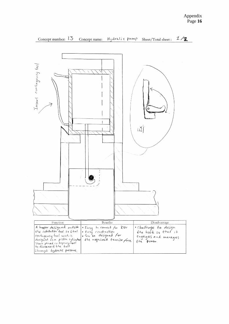
for ROV.
Challenge to
design the hook
so it manages
the stress. Easy
construction.

21
Concept Description Advantages Disadvantages
16
The hydraulic contingency
tool (left side). It’s
connected to the lock pin
(right side) in a contingency
situation.
Hydraulic
pressure is
used, keeping
moving parts
down.
The connection
between the CT
and lock pin will
experience high
stresses.
Low
modification on
existing tool.

22
6.2 First selection process
A Pugh matrix was done to distinguish bad concepts (sketch phase) from good ones see
Appendix A. Some concepts (sketch phase) were similar and therefore all sketches were
divided into four concept groups for easier selection process. Concept group one was
eliminated. All remaining concept groups were divided in subgroups for concept phase 2 see
Figure 6.1.
Figure 6.1- Concept Phase 1 chart
Concept Group 1
Concept group 1 had the focus to a new design on the bolt.
This concept group was made before all the design criteria were collected from Aker
Solutions. Aker Solutions does not want any changes on these bolts, therefor this concept
group was eliminated.
Concept Group 2
Concept group 2 consists of concept (sketch) 15 that uses a hydraulic arm to move the lever.
This concept was already nearly a working solution and would work on the IT today,
therefore further development wasn’t necessary. Group 2.1 pass to Concept Phase 2.
Concept Group 3
Concept group 3 consists of concepts (sketches) that are designed with a mechanical solution.
We together with Martin Stegberg have decided that three subgroups 3.1, 3.2 and 3.3 will be
developed as shown in group 3.1-3.3.
Concept Phase 1 (sketches)
Concept Group 1
Sketshes: 1, 2, 3, 4, 5, 6, 8, 9
Eliminated
Concept Group 2
Sketch: 15
Group 2.1
Concept Group 3
Sketches: 7, 11, 12, 13
Group 3.1 Group 3.2
Concept Phase2
Group 3.3
Concept Group 4
Sketches: 10, 14, 16
Group 4.1

23
Group 3.1
A horizontal operating lock pin works through a horizontal motion to lock and unlock the lock
pin see Figure 6.2. This concept idea is to have a solution with is mounted directly on the IT
which means that a CT will not be necessary. Group 3.1 passed to Concept Phase 2.
Figure 6.2- Vertical rotation to horizontal moment
Group 3.2
This idea is to get a vertical rotation to a horizontal rotation see Figure 6.3. The horizontal
rotation will make the screw bolt to spin out from its locked position using a torque tool.
Group 3.2 passed to Concept Phase 2.
Figure 6.3-Horizontal to vertical rotation

24
Group 3.3
The horizontal rotation is moved up using different mechanical components see Figure 6.4.
Group 3.3 passed to Concept Phase 2.
Figure 6.4-Horizontal to horizontal rotation
Concept Group 4
Hydraulic pressure will be used to operate the CT see Figure 6.5. A solution using a hydraulic
piston will be developed. Group 4.1 passed to Concept Phase 2.
Figure 6.5-Hydraulic solution

25
6.3 Concept phase 2
Remaining groups after concept phase 1 is: Group 2.1, 3.1, 3.2, 3.3 and 4.1 see Figure 6.1.
The best parts from all ideas in each group were picked and combined to a new design. When
the new design was developed, 3D CAD-models was made in each group. It will gives a
better view of concepts and thereby easier to evaluate. Description, benefits and drawbacks
for each group was discussed and sees in each groups table.
Table 6.2-Group: 2.1
Group: 2.1- Hydraulic arm
Number Description
1 Hook
2 Hydraulic cylinder
3 Interface to IT
Description of concept Advantages Disadvantages
The concept operates on
the lever system and
connects on top of the
installation tool and the
hydraulic arm connects to
the lever with a hook.
Easy to operate for ROV Need to modify installation tool for
connection. Few parts
Easy to connect on installation tool. Need buoyancy block because of
the weight.
1 2 3

26
Table 6.3-Group: 3.1
Group: 3.1- Vertical rotation to horizontal movement
Number Description
1 Lock pin (racked)
2 Standard holder for torque tool
3 ROV-handle
Description of concept Advantages Disadvantages
This concept is directly
mounted on the IT. The
rotation is transmitted
through a gear which is
coupled to a rack which
moves the lock pin on the
IT. The ROV can connect
a torque tool to gain more
torque than from the
ROV arm.
Moving the vertical rotation to
horizontal movement.
After connection a torque tool is
needed to operate the tool.
Manages the envelope Complicated design
Easy to connect a torque tool Using gears
2
1
3

27
Group: 3.2- Horizontal to vertical rotation
In group 3.2 two solutions A and B were developed.
Table 6.4-Solution A
Solution A- Propshaft
Number Description
1 Standard connection for torque tool
2 Propshaft
3 Interface to IT
4 Interface to CT
Description of concept Advantages Disadvantages
This concept can only be
connected to the screw
bolt system on the IT.
After connected to the IT
a torque tool connects to
a standard holder for
torque tools. The CT
transmits the torque
through a propshaft that
is articulated in a fixture.
The rotation led through a
shaft to the screw bolt by
a connection between the
shaft and bolt.
Moving the rotation from
horizontal rotation angle to
withstand the envelope
After the CT is connected a torque
is required to operate
Few parts A big propshaft is required to
handle the force Easy to operate for ROV
The CT to heavy and needs
buoyancy blocks
1 4
2
3

28
Table 6.5-Solution B
Solution B- Helical gears
Number Description
1 Standard connection for torque tool
2 Helical gears
3 Interface to IT
4 Interface to screw bolt
Description of concept Advantages Disadvantages
This concept can only be
connected to the screw
bolt system on the IT.
The concept transmits
torque throw helical
gears. A torque tool
connects to the CT with a
standard torque tool
connecter. The rotation
transmits through a shaft
to the helical gears that
transmits the rotation to
the screw bolt through the
connection on the shaft.
Moving the rotation from the
horizontal rotation to vertical
rotating
After the CT is connected a torque
is required to operate
Few parts Difficult to calculate helical gears
Easy to operate for ROV The CT to heavy and needs
buoyancy blocks
Gears are undesirable at subsea
1 3
2
4

29
Table 6.6-Group: 3.3
Group: 3.3- Horizontal to horizontal rotation
Number Description
1 Standard holder for torque tool
2 Gear wheel
3 Connection to IT
4 Interface to CT
5 Gear wheel
Description of concept Advantages Disadvantages
This concept can only be
connected to the screw
bolt system on IT. Two
gears move the rotation
up on the upper part of
IT, that’s give ROV more
space to operate with.
The lower gear is
connected to the screw
bolt through a shaft what
connect and transmit the
torque from the torque
tool. The torque tool
connects to CT with a
standard torque tool
connecter.
Moving the rotation from lower to
upper part
After connection, a torque tool is
needed to operate the contingency
tool
Easy for ROV to operate Gear is undesirable at subsea
Easy to dimension and design Concept is heavy
Easy to connect CT to IT
1 3
2
4 5

30
Table 6.7-Group: 4.1
Group: 4.1-Hydraulic pulling solution
Number Description
1 Hydraulic cylinder
2 Rod
3 Lock pin connection to rod
Description of concept Advantages Disadvantages
This concept use
hydraulic power to
release the lock pin.
A connection between the
rod and the lock pin will
connect the two parts.
Hydraulic pressure
transfers from ROV to
the cylinder.
No mechanical parts May be hard to spot hydraulic leeks
on cylinder Using hydraulic pressure to move
the lock pin, this means that no
mechanical gear is used Difficult to make it work in both
directions. Push and Pull
Few parts
No extra standard tool is required
1
3
2

31
6.4 Second selection process
From these five groups one concept group was chosen for further development, see Figure
6.6. Together in a meeting with Martin Stegberg were all groups discussed and the result will
be listed below.
Figure 6.6- Concept Phase 2
Group 2.1
Concept fulfills the requirement for a subsea tool and design basis if a buoyancy block is
attached to the tool. To connect this concept, major changes on the IT structure is necessary.
This results in major calculation and FEM-analyses for the IT structure.
It was decided to be a backup concept if the other concepts would not work in consideration
with Aker Solutions.
Group 3.1
This concept include components that not has a sufficient reliability for subsea conditions.
No further development was made.
Group 3.2
Group 3.2 with the two different solutions A and B was removed as a potential solution, due
to the difficulties to make a construction which would manage the design basis. Also it would
be difficult to make a construction which has a sufficient reliability when a mechanical
component is used.
Group 3.3
This concept include components that has not a sufficient reliability for subsea conditions.
No further development was made.
Group 4.1
This concept group has lots of benefits and fulfills the requirements for subsea tools and
hydraulic cylinders have been used in several other ROV tools.
Group 4.1 was then chosen for further development.
Concept Phase 2
Group: 2.1 Group: 3.1 Group: 3.2 Group: 3.3
Solution A
Solution B
Group: 4.1
Further Development Eliminated

32
7 FURTHER DEVELOPMENT OF CONCEPT Group 4.1 is a hydraulic solution that operates on the IT with a lever system see Figure 7.1.
The 3D-model that was developed in concept phase 2 was used as a basis for further
development and to a final concept.
Figure 7.1- Group 4.1
The big challenge was to minimize the CT as much as possible. A smaller CT is easier for the
ROV to maneuver. A table with cylinder criteria was developed, see Table 7.1.
Table 7.1- Cylinder criteria
Criteria Value
Stroke Length 80 mm
Hydraulic Pressure 680 bar
Max length 240 mm
Pull force 20 metric ton
The company Malmorstad [12] could produce a cylinder that achieve our cylinder criteria and
with even better max length to 200 mm.
Data from Malmorstad were used to make an envelope for the hydraulic cylinder, see Figure
7.2
Figure 7.2-Envelope of the hydraulic cylinder

33
CT with splint system
A basic structure was made for further development. The final design needs two connecting
systems; one that connect the CT to the IT, one that connect the rod to the lock pin. To make
the operation for the ROV maneuverable, few motions as possible is to prefer. When
designing the connecting systems it was important to manage the tension in structure and fit
the envelope of HCS.
To connect CT to IT an outer bayonet coupling is used. Rod and lock pin is connected
through a splint. To operate the CT a control box is needed, see Table 7.2. This protects the
main components: mini booster, pressure reducer, pressure gauge, receptacle, and hydraulic
pipes.
Table 7.2 – Concept with splint
Figure Description
Number Description
1 Lever system
2 Interface to IT
3 Pressure gauge
4 Fishtail
5 Receptacle
6 Splint
7 Control box
Concept installed together with
the installation tool
6
7
1
2
3
4
5

34
This concept resolves in three main motions for ROV to operate CT these motions is
described inTable 7.3.
Table 7.3-Motions
A virtual installation with the whole structure was simulated in SolidWorks. The simulation
found it very difficult with the rotation in order to connect the CT to IT without impacting the
surrounding structure. Another problem was that the rod could rotate freely. This means that
the rod could rotate in an undesirable situation where it is impossible to connect CT on IT.
These problems were discussed with Martin Stegberg for further development.
Motion Description
1 Connect the CT to the IT with rotating CT 90o clockwise
2 Connect the splint to the rod and the lock pin
3 Operate the CT

35
CT with two bayonet couplings
Further development of the concept was made and a final design emerged. The rod was
designed with same bayonet coupling as the cylinder, see Table 7.4.This design decreased
movements for ROV. To stop the rotation of the rod, a guide pin was developed. It holds the
rod in right position.
Table 7.4-CT with two bayonet copulings
Figure Description
Number Description
1 Receptacle
2 ROV handel
3 Control box
4 Pressure gauge
Number Description
1 Outer bayonet coupling
2 Inner bayonet coupling
Number Description
1 Guide pin
This solutions resolve in two main motions for ROV to operate CT see Table 7.5.
Table 7.5-Motions
Motion Description
1 Connection between; CT to the IT, rod to the lock pin is done though a 90o clockwise
rotation.
2 Operate the CT
2
2
1
4 3
1
1

36
Installed CT
Table 7.6 shows final concept connected to IT and HCS.
Table 7.6-Connected contingency tool
Figure Description
CT (Contingency tool) connected to the IT
(installation tool)
Installation tool with the contingency tool
connected to the HCS
A closer view on the contingency tool when it
is connected to the installation tool.

37
8 THE FINAL DESIGN Together with Aker Solution the final design was named LockDog Contingency Tool
(LDCT). All technical information and details of the parts in the final concept is described in
this chapter. Further technical information for the LDCT is described in OMM see appendix
D.
8.1 Design Specifications Table 8.1 describes the technical information and envelope about the LDCT. LDCT is
designed so it meets the design basis which was set at the beginning of the project. Some
technical specifications are from Malmorstad [12] and miniBooster [3] which representing
certain parts in the final design.
Table 8.1-Tecnichal specifications
Measurement Value
Operational force capacity Pull 20 metric tonnes (680 bar) Push 10 metric tonnes (200 bar)
Max. allowable water depth 3 000 m (10 000 ft)
Operation temperature range 0 to + 50 oC
Input pressure 170-207 bar (2465 - 3000 psi)
Input flow 0-14 l/min (0 – 3.7 gal/min)
Maximum working Pressure retract (after booster) 680 bar (9860 psi)
Maximum working Pressure extend 200 bar (2900 psi)
Design Pressure hydraulic system 207 bar (3000 psi)
Check Valves In Dual Port Hot Stab / In Dual Port Receptacle
Hoses/ piping For subsea usage
Stroke length 80 mm
Weight in air 39 kg
Weight in water 35 kg
38
8.2 Assembly and parts
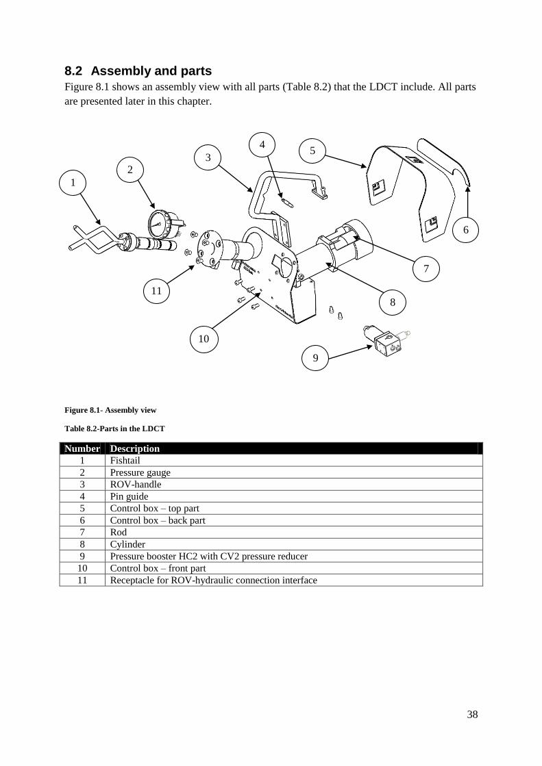
Figure 8.1 shows an assembly view with all parts (Table 8.2) that the LDCT include. All parts
are presented later in this chapter.
Figure 8.1- Assembly view
Table 8.2-Parts in the LDCT
Number Description
1 Fishtail
2 Pressure gauge
3 ROV-handle
4 Pin guide
5 Control box – top part
6 Control box – back part
7 Rod
8 Cylinder
9 Pressure booster HC2 with CV2 pressure reducer
10 Control box – front part
11 Receptacle for ROV-hydraulic connection interface
9
10
0
11
2
1
8
3 5
7
6
4

39
Cylinder and rod
The cylinder and rod is the main part on LDCT, see Figure 8.2 and Table 8.3. Because of the
narrow dimensions on the envelope for HCS, the cylinder with its outer bayonet coupling is
made in one piece. This design is engineered with the corporation with the company
Malmorstad [12] to fulfill the design basis and the material strength. The rod has also a
bayonet coupling to connect on the lock pin.
Figure 8.2-Cylinder and Rod
Table 8.3-Description
Number Description
1 Rod
2 Guide pin
3 Hydraulik cylinder
3
2
1

40
Control box
The main purpose for a control box is to protect and attach the vulnerable hydraulic parts and
pipes. Control box is made from a 3 mm painted sheet material which is divided into three
different parts for easier manufacturing, see Figure 8.3 and Table 8.4.
Figure 8.3-Control box
Table 8.4-Controll box
Number Description
1 Control box
2 Front plate
3 Top plate
4 Back plate
3 4
1
2

41
Table 8.5 describes imported design criteria’s for control box. These criteria’s was imported
to manage the design basis and at the same time include all hydraulic parts.
Table 8.5- Control box.
Figure Description
To minimize the size of the control box, parts
and pipes are place strategically.
The minimum bending radius on pipes has
been taken in consideration.
The control box is design so it builds from the
backside of the cylinder and forward.
This is important to reduce the length of the
CT.
The control box is mounted together with
ROV handle with four bolts.
To not impact the lever in the installation
process, the control box is design with the
same angle as the lever in locked position
(α).
α

42
Mini booster and reducer
The mini booster (Figure 8.4) function is to increase the hydralic pressure with four times
from ROV’s hydralic power. This is important to achieve the high pressure to reduce
cylinders dimensions. Mini boosters is a common part in standard tools to increase the ROV’s
hydraulic pressure. In the LDCT mini booster is connected to a reducer (Table 8.6) that limits
the inlet pressure from ROV to required value see Diagram 8.1. The information about mini
booster and reducer is taken from the company miniBooster [3],[4].
Figure 8.4-miniBooster with reducer
Table 8.6- miniBooster with reducer
Number Description
1 Hydraulic pressure booster
2 Hydraulic pressure reducer
2
1

43
Diagram 8.1-Pressure/Force diagram
0
20000
40000
60000
80000
100000
120000
140000
160000
180000
200000
220000
0 25 50 75 100 125 150 175 200
Forc
e [
N]
Pressure [Bar]
Pressure Force EXTEND
RETRACT
44
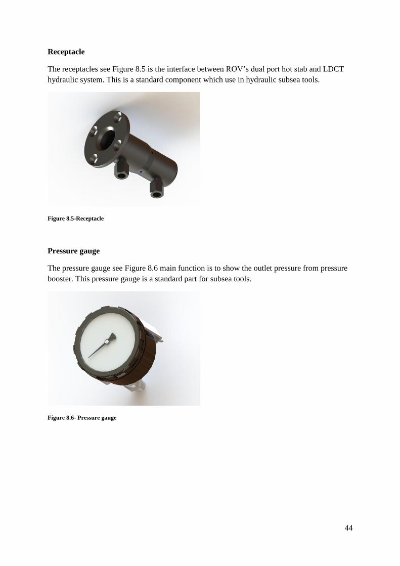
Receptacle
The receptacles see Figure 8.5 is the interface between ROV’s dual port hot stab and LDCT
hydraulic system. This is a standard component which use in hydraulic subsea tools.
Figure 8.5-Receptacle
Pressure gauge
The pressure gauge see Figure 8.6 main function is to show the outlet pressure from pressure
booster. This pressure gauge is a standard part for subsea tools.
Figure 8.6- Pressure gauge

45
Lever System
To connect the CT to the lever system some changes in the exciting design were needed. The
difference between the existing and the new design can be seen in Table 8.7.
Table 8.7-Lever system
Figure Description
This is the new design with the interface for the
LDCT. Design changes is marked and described
in the figure.
Number Description
1 Outer bayonet coupling on guide pin
2 Inner bayonet coupling on lock pin
Replace version
2
1

46
8.3 FEM
To see if the rod design would manage a force of 20 metric tons several simulation in FEM
was made in SolidWork. A green arrow is equal to a fixture, meaning it is locked to its
position. A pink arrow shows where the evenly distributed force is disposed.
Figure 8.7-FEM-model of rod
Figure 8.7 showing von Mises stresses from 0 MPa to 710 MPa. Yield strength for the
material is 710 MPa and everything over 710 will be showed as red.
Some area between flanged and outer surface are over 710MPa which means that some
material around the edge will be plasticized and can be a problem due to fatigue. Aker
Solution has a requirement that the strain energy have to be below 10% in a point and 2% in a
section [9].

47
To control the results an existing tool was chosen to compare the rod, the tool and FEM-
analyses can be seen in Figure 8.8. This is an existing tool at Aker Solutions and has a similar
design as the LDCT.
Figure 8.8-Bolt puller, FEM-model of von Mises
Both FEM-analyses, as shown in Figure 8.7 and Figure 8.8, has similar stress image which
means that the LDCT probably manage the stress. Further calculations will be made by Finite
Element Analysis Specialist personal at Aker Solution.
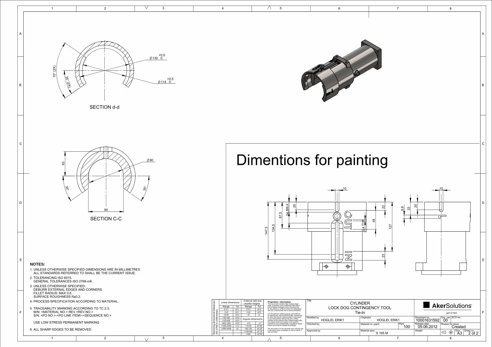
8.4 Drawings All drawings are designed according to Aker Solutions standards and Aker Solutions
templates for drawings are used.
Three kinds of templates are used, depending on what kind of tasked which is performed:
welding, machining and assembly drawings.
If nothing is specified these standards below are used.
1. Unless otherwise specified dimensions are in millimeters, all standards referred to
shall be the current issue.
2. Tolerancing ISO 8015 [5]
General tolerancing ISO 2768-mK [6]
3. Unless otherwise specified deburr external edges and corners.
Fillet radius: Max=0,8.
Surface roughness RA 3,2.
All drawings can be seen in appendix C.

48
8.5 Hydraulic schedule
A hydraulic schedule was made to control if the piping would fit the control box. In Figure
8.9 and in appendix C shows the hydraulic schedule over the LDCT. This includes all
hydraulic parts in the control box, see Table 8.8.
Figure 8.9-Hydraulic schedule
Table 8.8- Hydraulic schedule
Number Description
1 Receptacle
2 Hydraulic pressure reducer
3 Hydraulic pressure booster
4 Pressure gauge
R Hydraulic return
Z Return from cylinder
IN Low pressure hydraulic inlet
H High pressure hydraulic outlet
1 2 3 4
R
Z
IN H

49
8.6 Clearance
Tools for ROV need to be as uncomplicated as possible to operate. Therefore it is important
that the clearance is in right place.
The LDCT is designed so that the outer bayonet coupling on the cylinder matches the
installation tool before the rod and lock pin which makes it easy for the ROV to connect.
When the outer bayonet coupling is in place, the ROV knows that the rod also has connected
to the lock pin.
In Figure 8.10 shows the outer clearance and in Figure 8.11 shows the inner clearance.
Figure 8.10-Outer clearance
Figure 8.11-Inner clearance
Outer clearance
Max clearance: 3 mm
Min clearance: 1.5 mm
Inner clearance
Max clearance: 5.7 mm
Min clearance: 4.7 mm

50
9 CALCULATIONS In this chapter minor calculations will be made. Calculations are made to determine the
minimum diameter for: piston, cylinder and lock pin.
9.1 Piston Calculations determine the minimum diameter of the cylinder see Figure 9.1. Material used in
this calculation is a Normalized carbon steel. The company who later will do the
manufacturing of the hydraulic piston will set the final dimensions.
Data
Material: SS141650-01 (Normalized Steel) [8]
Equations
Force
(9.1)
Area:
(9.2)
Radius:
√
√
(9.3)
Conclusions
The hydraulic piston radius r needs to be at least 14.2 mm to be able to fulfill the operation
without any plasticization of the material.
Figure 9.1-Piston stress
The diameter D
Force F

51
9.2 Cylinder
Calculations to determine the inner diameter D for the hydraulic cylinder. Calculations of
pressure and area are made to get the necessary force see Figure 9.2.
Data
Equations
Minimum required area.
(9.4)
Required diameter depends on the hydraulic piston diameter. In this equation a diameter of
d=35 mm will be used for the piston.
(9.5)
Minimum diameter
(
) √
√
(9.6)
Conclusions
Required minimum diameter D for the cylinder needs to be at least 70 mm to get a force of 20
ton and a piston diameter of 35 mm. The required pressurized area is .
Force F
Pressure P
D d
Area A
Figure 9.2-Cylinder

52
9.3 Shear stress analysis for the lock pin
Stress calculations to determine maximum force one edge will be able to handle.
Figure 9.3-Stress areas
Data
Calculations
Area calculations:
(9.7)
Force:
(9.8)
(9.9)
(9.10)
Conclusions
The area which the force will be present is 1553 mm2, According to our calculations will the
structure manage a force F of 662 kN which is around three times higher than the required
one.
Shear Stress Area
Force F

53
10 CONCLUSIONS In this chapter the conclusions of our work will be handled. We have chosen to present our
conclusion in point form. This gives a better and clearer view.
A completely new contingency tool for the HCS system was developed from scratch.
In theory our contingency tool solves the problem. This was the purpose of this
project.
We used a new type of pressure booster that includes a pressure reducer (HC2W 4,0-
B-1S with CV2). This reduces the piping and makes our design possible to fit the
envelope.
A special made hydraulic cylinder was developed and approved by the company
Malmorstad. This made it possible to reduce the length of the contingency tool.
Calculations and FEM-analysis has been done to ensure the design would manage
stresses.
Minor changes on the installation tool were made to have an interface for the
contingency tool.
54
11 DISCUSSION AND REFLECTION Important discussion about relevant topics will be discussed in this chapter.
The purpose with this work was to develop a contingency tool to solve a problem in the HCS
installation process. A contingency tool was developed which can be connected to the lever
system. To lock the tool with the lever system, bayonet couplings were used.
The system is designed according to Aker Solution to manage a dragging force of 20 metric
tons (around 200 000 N). The final design could not be tested due to a prototype was never
produced. This tool will have around 20 times higher pull force than from the ROV and make
this design reliable. A construction to manage a bigger force would be very hard to design.
To make the installation easier the CT to the IT had a built in clearance. This makes it easier
for ROV to connect and operate the CT without needing to be in the exact right place in the
installation process, making the installation process more confident.
To ensure the design theoretically; cylinder and rod was designed against the yield strength.
Calculations and FEM-analysis was done in SolidWorks. Final calculations will be done by
Finite Element Analysis Specialist and approved by Aker Solutions.

55
REFERENCES
Homepages
1. Herron.J, (2010), "3D Model-Based Design: Setting the Definitions Straight",
MCADCafe, (2012-05-25)
http://www10.mcadcafe.com/nbc/articles/2/867959/3D-Model-Based-Design-Setting-
Definitions-Straight
2. Wikipedia, Pugh-matrix, www.wikipedia.com, (2012-04-15)
http://en.wikipedia.org/wiki/Decision-matrix_method
3. Sundström.P, www.miniBooster.com, HC2, (2012-04-15)
http://www.minibooster.com/version_english/01_products/02_oil_boosters_uk/hc2_uk
.htm
4. Sundström.P, www.miniBooster.com, Pressure reducer CV2 for miniBooster HC2,
(2012-04-15)
http://www.minibooster.com/version_english/01_products/06_valve_housing_uk/cv2_
uk.htm
5. ISO 8015, International Organitation for Standardization, www.iso.com, (2012-04-30)
http://www.iso.org/iso/catalogue_detail.htm?csnumber=55979
6. ISO 2768-mK, Swedish Standards institute, www.sis.se, (2012-04-30)
http://www.sis.se/metrologi-och-m%C3%A4tning-fysikaliska-
fenomen/l%C3%A4ngd-och-vinkelm%C3%A4tning/toleranser-och-passningar/ss-iso-
2768-1
7. FORUM, www.f-e-t.com, ROV-XLX150, (2012-03-20)
http://www.f-e-t.com/images/uploads/data-
sheets/FOR158_PerryXLX150_Data_Sheet_032212.pdf
Literature
8. Dahlberg.T, Teknisk Hållfasthetslära Formelsamling 3:de upplagan Studentlitteratur
2011, page .A1 Material
9. BS ISO 13628-7:2005, Petroleum and natural gas industries - Design and operation of
subsea production systems: Part 7: Completion/workover riser systems: ICS
75.180.10: page 201-203
10. Persson G, FEM-Modellering med Pro/Mechanica Wildfire V4.0, comp, Chalmers
(2010)
Personal referensers
11. Stegberg M, Aker Solutions Tie-in
12. Orstad.L, Malmorstad A/S.

Appendix
Page 1
APPENDIX A PUGH-MATRIX
Pugh-
Matrix

Summary Chart: First eliminationPROJECT:
Referens
Weight factor Koncept 1 Koncept 2 koncept 3Will be abel to use contingency tool -1 1 1 1
Meet the requirements of the envelope 1 1 1 1No complex parts 1 1 -1 -1
No change of installations tool -1 0 -1 -1Easy to use 1 1 1 1
Easy to conect contingency tool -1 1 1 -1Manage natural conditions 1 1 -1 -1
Can be operat with ROV 1 1 1 1Change the strength characteristics on the bolt 0 0 0 0
Number better: +5 +7 +5 +4Number worse: -3 0 -3 -4Number same: 1
-1: Alternative is worse than the Datum on the Criteria0: Alternative is indistinguishable from the Datum on the Criteria1: Alternative is better than the Datum on the Criteria
Pugh Concept Selection Process

Summary Chart: First eliminationPROJECT:
Will be abel to use contingency toolMeet the requirements of the envelope
No complex partsNo change of installations tool
Easy to useEasy to conect contingency tool
Manage natural conditionsCan be operat with ROV
Change the strength characteristics on the boltNumber better: Number worse: Number same:
-1: Alternative is worse than the Datum on the Criteria0: Alternative is indistinguishable from the Datum on the Criteria1: Alternative is better than the Datum on the Criteria
Pugh Concept Selection Process
Koncept 4 Koncept 5 Koncept 61 1 -11 1 1-1 -1 1-1 -1 -11 1 11 1 -1-1 -1 -11 1 10 0 0
+5 +5 +4-3 -3 -4

Summary Chart: First eliminationPROJECT:
Will be abel to use contingency toolMeet the requirements of the envelope
No complex partsNo change of installations tool
Easy to useEasy to conect contingency tool
Manage natural conditionsCan be operat with ROV
Change the strength characteristics on the boltNumber better: Number worse: Number same:
-1: Alternative is worse than the Datum on the Criteria0: Alternative is indistinguishable from the Datum on the Criteria1: Alternative is better than the Datum on the Criteria
Pugh Concept Selection Process
Koncept 7 Koncept 8 Koncept 91 1 01 1 1-1 1 -1-1 -1 -11 1 11 1 0-1 1 11 1 00 0 -1
+5 +7 +3-3 -1 -3

Summary Chart: First eliminationPROJECT:
Will be abel to use contingency toolMeet the requirements of the envelope
No complex partsNo change of installations tool
Easy to useEasy to conect contingency tool
Manage natural conditionsCan be operat with ROV
Change the strength characteristics on the boltNumber better: Number worse: Number same:
-1: Alternative is worse than the Datum on the Criteria0: Alternative is indistinguishable from the Datum on the Criteria1: Alternative is better than the Datum on the Criteria
Pugh Concept Selection Process
Koncept 10 Koncept 11 Koncept 120 0 01 1 1-1 -1 -1-1 -1 -11 1 10 0 01 1 10 0 0-1 -1 1+3 +3 +4-3 -3 -2

Summary Chart: First eliminationPROJECT:
Will be abel to use contingency toolMeet the requirements of the envelope
No complex partsNo change of installations tool
Easy to useEasy to conect contingency tool
Manage natural conditionsCan be operat with ROV
Change the strength characteristics on the boltNumber better: Number worse: Number same:
-1: Alternative is worse than the Datum on the Criteria0: Alternative is indistinguishable from the Datum on the Criteria1: Alternative is better than the Datum on the Criteria
Pugh Concept Selection Process
Koncept 13 Koncept 14 Koncept 151 1 -11 1 11 1 1-1 -1 -11 1 11 1 01 1 11 1 10 0 0
+7 +7 +5-1 -1 -2

Appendix
Page 1
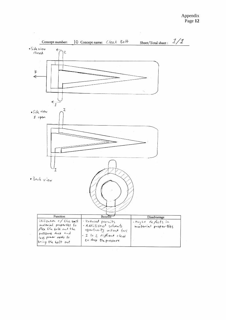
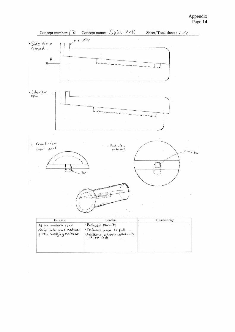
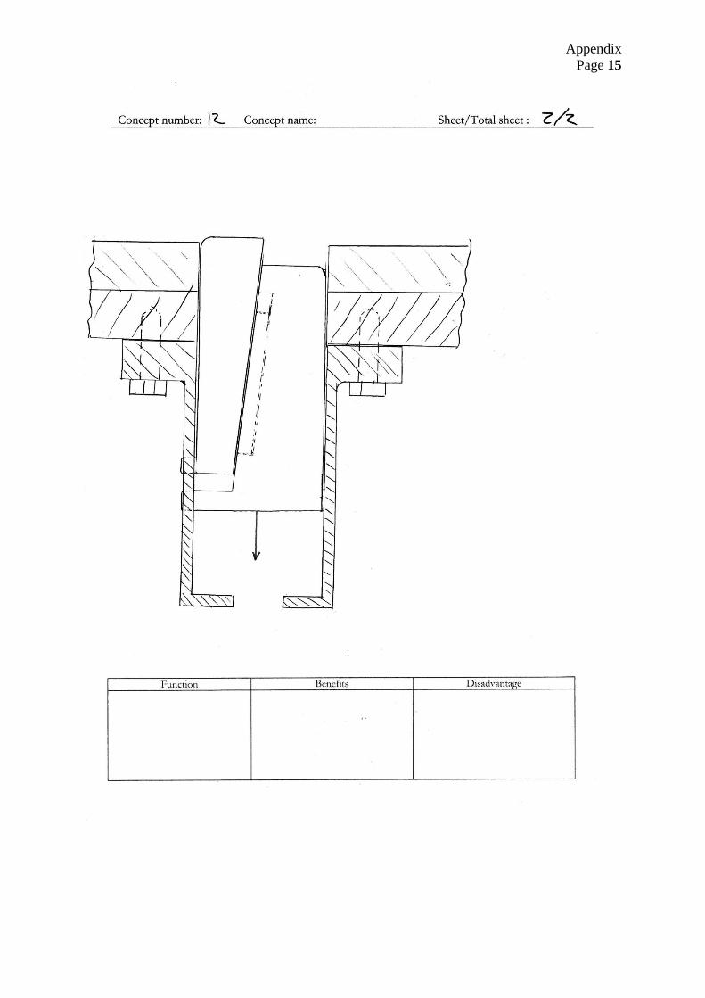
APPENDIX B CONCEPTS
Concepts

Appendix
Page 2

Appendix
Page 3

Appendix
Page 4

Appendix
Page 5

Appendix
Page 6

Appendix
Page 7

Appendix
Page 8

Appendix
Page 9

Appendix
Page 10

Appendix
Page 11
Appendix
Page 12

Appendix
Page 13
Appendix
Page 14
Appendix
Page 15
Appendix
Page 16

Appendix
Page 17

Appendix
Page 18

Appendix
Page 1
APPENDIX C DRAWINGS FOR MAUFATURING
Drawings

in all events upon completion of use for which it
Proprietary informationThis document contains Aker Subsea legal entity proprietary and confidential information that is legally privileged and is intended only for the person or entity to which it is addressed and any unauthorised use is strictly prohibited.
It is provided for limited purpose and shall not be reproduced, stored electronically, transferred to other documents, disseminated or disclosed to any third parties without the prior written consent of the relevant Aker Subsea legal entity. Any attachments are subject to the specific restrictions and confidentiality regulations stated therein and shall be treated accordingly.
The document is to be returned upon request and
was provided.
part of Aker
TMSolutionsAker
A3Created
0005.06.2012
10001631662
PETTERSSON, JONAS2
PETTERSSON, JONAS2
Title
Modified by
Checked by
Approved by
Originator
Material no. (part)
Material spec.
Document no.
Release date
Doc. ver.
Reason for issue
ECO no.
Size Sheet no.
LOCK DOGLOCK DOG CONTINGENCY TOOL
ASSEMBLY
Plant100
Weight38456.74 1 of 2
C
B
A
1 2 3 4 8
D
5
E
F F
C
B
D
E
A
6 7
1 86 742 3 5
NOTES:
1. UNLESS OTHERWISE SPECIFIED DIMENSIONS ARE IN MILLIMETRES ALL STANDARDS REFERRED TO SHALL BE THE CURRENT ISSUE.
2. PROCESS SPECIFICATION ACCORDING TO MATERIAL.
ITEM NO. PART NUMBER DESCRIPTION QTY.
1 10001618051 90boj 32 10001618061 C.Joint 23 MALE CONNECTOR-
0.375Tx0.375 NPTsolidworks-lok male
connector 2
4 MALE CONNECTOR-0.375Tx0.250 PIPE
solidworks-lok male pipe weld connector 2
5 10001617941 CYLINDER 16 MALE BRANCH TEE-0.375T solidworks-lok tubing
branch tee 17 10001617943 ROV HANDLE 18 10001618022 Tube_4-Final_concept 19 10001617944 CB_FRONT 1
10 ISO 4762 M8 x 30 --- 30N socket head cap screw_iso 2
12 10001618050 SEAL BACK 117 Washer ISO 7091 - 6 plain washer normal
grade c_iso 8
18 Washer ISO 7091 - 8 plain washer normal grade c_iso 8
19 10001617945 CB_TOP 120 10000450148 DP RECEPTACLE WITH
CV 1
21 10001321221 MANOMETER, 0-250 BAR 1
22 10001617946 minibooster_pressure 123 10001618013 CB_BACK 124 10000451874 PROT STAB, DUAL , ISO
A, FISHTAIL 1
25 Hexagon Flange Nut ISO - 4161 - M12 - N
hex flange nut gradea_iso 4
26 ISO 7380 - M6 x 16 --- 16N socket button head screw_iso 4
27 ISO 7380 - M6 x 12 --- 12N socket button head screw_iso 4
28 ISO 4762 M8 x 35 --- 35N socket head cap screw_iso 4
29 ISO 4762 M5 x 12 --- 12N socket head cap screw_iso 4
30 ISO 4762 M8 x 20 --- 20N socket head cap screw_iso 2
31 ISO 10642 - M12 x 30 --- 30N socket countersunk head screw_iso 4
32 10001618046 BRACKET 133 10001618033 GUID PIN 134 10001618035 SEAL FRONT 135 10001618036 SEAL1 236 10001618038 SEAL2 137 10001618040 SEAL3 1
21
31
20
19
30
10
5
7
9
33
28
DETAIL A32
22
27
23
24
27
25
26
A

in all events upon completion of use for which it
Proprietary informationThis document contains Aker Subsea legal entity proprietary and confidential information that is legally privileged and is intended only for the person or entity to which it is addressed and any unauthorised use is strictly prohibited.
It is provided for limited purpose and shall not be reproduced, stored electronically, transferred to other documents, disseminated or disclosed to any third parties without the prior written consent of the relevant Aker Subsea legal entity. Any attachments are subject to the specific restrictions and confidentiality regulations stated therein and shall be treated accordingly.
The document is to be returned upon request and
was provided.
part of Aker
TMSolutionsAker
A3Created
0005.06.2012
10001631662
PETTERSSON, JONAS2
PETTERSSON, JONAS2
Title
Modified by
Checked by
Approved by
Originator
Material no. (part)
Material spec.
Document no.
Release date
Doc. ver.
Reason for issue
ECO no.
Size Sheet no.
LOCK DOGLOCK DOG CONTINGENCY TOOL
ASSEMBLY
Plant100
Weight38456.74
C
B
A
1 2 3 4 8
D
5
E
F F
C
B
D
E
A
6 7
1 86 742 3 52 of 2
NOTES:
1. UNLESS OTHERWISE SPECIFIED DIMENSIONS ARE IN MILLIMETRES ALL STANDARDS REFERRED TO SHALL BE THE CURRENT ISSUE.
2. PROCESS SPECIFICATION ACCORDING TO MATERIAL.
SECTION G-G
29
FE
SECTION C-C
DETAIL D
360 2
86
375
344
C
C
B
B
379
498
575
G
G
D
SECTION B-B
DETAIL E DETAIL F

in all events upon completion of use for which it
Proprietary informationThis document contains Aker Subsea legal entity proprietary and confidential information that is legally privileged and is intended only for the person or entity to which it is addressed and any unauthorised use is strictly prohibited.
It is provided for limited purpose and shall not be reproduced, stored electronically, transferred to other documents, disseminated or disclosed to any third parties without the prior written consent of the relevant Aker Subsea legal entity. Any attachments are subject to the specific restrictions and confidentiality regulations stated therein and shall be treated accordingly.
The document is to be returned upon request and
was provided.
part of Aker
TMSolutionsAker
A3Created
0005.06.2012
10001631353
PETTERSSON, JONAS2
PETTERSSON, JONAS2
Title
Modified by
Checked by
Approved by
Originator
Material no. (part)
Material spec.
Document no.
Release date
Doc. ver.
Reason for issue
ECO no.
Size Sheet no.
ROD_CYLINDERLOCK DOG CONTINGENCY TOOL
ASSEMBLY
Plant100
Weight 1 of 1
C
B
A
1 2 3 4 8
D
5
E
F F
C
B
D
E
A
6 7
1 86 742 3 5
NOTES:
1. UNLESS OTHERWISE SPECIFIED DIMENSIONS ARE IN MILLIMETRES ALL STANDARDS REFERRED TO SHALL BE THE CURRENT ISSUE.
2. PROCESS SPECIFICATION ACCORDING TO MATERIAL.
80 76 156
81

in all events upon completion of use for which it
Proprietary informationThis document contains Aker Subsea legal entity proprietary and confidential information that is legally privileged and is intended only for the person or entity to which it is addressed and any unauthorised use is strictly prohibited.
It is provided for limited purpose and shall not be reproduced, stored electronically, transferred to other documents, disseminated or disclosed to any third parties without the prior written consent of the relevant Aker Subsea legal entity. Any attachments are subject to the specific restrictions and confidentiality regulations stated therein and shall be treated accordingly.
The document is to be returned upon request and
was provided.
part of Aker
TMSolutionsAker
±0°10'
>1000-2000
Range
External radii andchamfer heights
Mac
hini
ng d
imen
sion
al to
lera
nces
ISO
276
8-m
(mill
imet
res)
Angular dimensions
Linear dimensions
Tol Range Tol0.5-3>3-6
>6-30>30-120
>120-400>400-1000
>2000-4000
±0.1±0.1±0.2±0.3±0.5±0.8±1.2±2
0.5-3 ±0.2±0.5±1
>3-6
≤10
>6
>10-50>50-120
>120-400>400
±1°±0°30'±0°20'
±0°05' A3Created
0005.06.2012
10001631592
HOGLID, ERIK1
HOGLID, ERIK1
Title
Modified by
Checked by
Approved by
Originator
Material no. (part)
Material spec.
Document no.
Release date
Doc. ver.
Reason for issue
ECO no.
Size Sheet no.
CYLINDERLOCK DOG CONTINGENCY TOOL
Tie-In
Plant100
Weight S 165 M
90°
45°
(3X)
115
3 5
C
B
A
1 2 3 4 8
D
5
E
F F
C
B
D
E
A
6 7
1 86 7421 of 2
NOTES:
1. UNLESS OTHERWISE SPECIFIED DIMENSIONS ARE IN MILLIMETRES ALL STANDARDS REFERRED TO SHALL BE THE CURRENT ISSUE.
2. TOLERANCING ISO 8015. GENERAL TOLERANCES ISO 2768-mK.
3. UNLESS OTHERWISE SPECIFIED: DEBURR EXTERNAL EDGES AND CORNERS. FILLET RADIUS: MAX 0,8. SURFACE ROUGHNESS Ra3,2.
4. PROCESS SPECIFICATION ACCORDING TO MATERIAL.5. TRACEABILITY MARKING ACCORDING TO TC 2.3: M/N: <MATERIAL NO.> REV.<REV.NO.> S/N: <PO NO.>-<PO LINE ITEM>-<SEQUENCE NO.>
USE LOW STRESS PERMANENT MARKING
6. ALL SHARP EDGES TO BE REMOVED
10
R5
90
15
0
107
R10
30
48
56
B
B
SECTION B-B
116 (4X)
75
90
6,8 19,8 (4X)M8
55
280
356
20
180
200
10
0
d
d
C
C
AA
SECTION A-A 50
15
180
46 + 0,50
4 X 45° TYP.
1
100 3 X 45°(4X)
100
6,8 THRU M8 (4X)
in all events upon completion of use for which it
Proprietary informationThis document contains Aker Subsea legal entity proprietary and confidential information that is legally privileged and is intended only for the person or entity to which it is addressed and any unauthorised use is strictly prohibited.
It is provided for limited purpose and shall not be reproduced, stored electronically, transferred to other documents, disseminated or disclosed to any third parties without the prior written consent of the relevant Aker Subsea legal entity. Any attachments are subject to the specific restrictions and confidentiality regulations stated therein and shall be treated accordingly.
The document is to be returned upon request and
was provided.
part of Aker
TMSolutionsAker
±0°10'
>1000-2000
Range
External radii andchamfer heights
Mac
hini
ng d
imen
sion
al to
lera
nces
ISO
276
8-m
(mill
imet
res)
Angular dimensions
Linear dimensions
Tol Range Tol0.5-3>3-6
>6-30>30-120
>120-400>400-1000
>2000-4000
±0.1±0.1±0.2±0.3±0.5±0.8±1.2±2
0.5-3 ±0.2±0.5±1
>3-6
≤10
>6
>10-50>50-120
>120-400>400
±1°±0°30'±0°20'
±0°05' A3Created
0005.06.2012
10001631592
HOGLID, ERIK1
HOGLID, ERIK1
Title
Modified by
Checked by
Approved by
Originator
Material no. (part)
Material spec.
Document no.
Release date
Doc. ver.
Reason for issue
ECO no.
Size Sheet no.
CYLINDERLOCK DOG CONTINGENCY TOOL
Tie-In
Plant100
Weight S 165 M
5
C
B
A
1 2 3 4 8
D
5
E
F F
C
B
D
E
A
6 7
1 86 742 32 of 2
NOTES:
1. UNLESS OTHERWISE SPECIFIED DIMENSIONS ARE IN MILLIMETRES ALL STANDARDS REFERRED TO SHALL BE THE CURRENT ISSUE.
2. TOLERANCING ISO 8015. GENERAL TOLERANCES ISO 2768-mK.
3. UNLESS OTHERWISE SPECIFIED: DEBURR EXTERNAL EDGES AND CORNERS. FILLET RADIUS: MAX 0,8. SURFACE ROUGHNESS Ra3,2.
4. PROCESS SPECIFICATION ACCORDING TO MATERIAL.
5. TRACEABILITY MARKING ACCORDING TO TC 2.3: M/N: <MATERIAL NO.> REV.<REV.NO.> S/N: <PO NO.>-<PO LINE ITEM>-<SEQUENCE NO.>
USE LOW STRESS PERMANENT MARKING
6. ALL SHARP EDGES TO BE REMOVED
Dimentions for painting
23
10
3,4
TY
P.
48
20
67,
5
134
,5
54,
5
147
,5
22
127
26,
4
SECTION d-d
0114 + 0,5 7
0° (2
X)
130 + 0,50
35° (2X)
SECTION C-C
63
90
35° 35°
90
33
10
20
8,8

in all events upon completion of use for which it
Proprietary informationThis document contains Aker Subsea legal entity proprietary and confidential information that is legally privileged and is intended only for the person or entity to which it is addressed and any unauthorised use is strictly prohibited.
It is provided for limited purpose and shall not be reproduced, stored electronically, transferred to other documents, disseminated or disclosed to any third parties without the prior written consent of the relevant Aker Subsea legal entity. Any attachments are subject to the specific restrictions and confidentiality regulations stated therein and shall be treated accordingly.
The document is to be returned upon request and
was provided.
part of Aker
TMSolutionsAker
±0°10'
>1000-2000
Range
External radii andchamfer heights
Mac
hini
ng d
imen
sion
al to
lera
nces
ISO
276
8-m
(mill
imet
res)
Angular dimensions
Linear dimensions
Tol Range Tol0.5-3>3-6
>6-30>30-120
>120-400>400-1000
>2000-4000
±0.1±0.1±0.2±0.3±0.5±0.8±1.2±2
0.5-3 ±0.2±0.5±1
>3-6
≤10
>6
>10-50>50-120
>120-400>400
±1°±0°30'±0°20'
±0°05' A3Created
0005.06.2012
10001631573
PETTERSSON, JONAS2
PETTERSSON, JONAS2
Title
Modified by
Checked by
Approved by
Originator
Material no. (part)
Material spec.
Document no.
Release date
Doc. ver.
Reason for issue
ECO no.
Size Sheet no.
RODLOCK DOG CONTINGENCY TOOL
MACHINING
Plant100
Weight
Dimensions from Malmorstad
50
5,2 X 30°
6,8 60
R1
19.8 M8 R5 16
70
BB
SECTION C-C
51
65
D D
SECTION B-B
65
80
-0 0,5
C
C
DETAIL A
R4 (2 X)
3,2 X 28° (2 X)A
124° (2 X)
3
7,5
+ 0,3
0
38,1 5
6° (2
X)
SECTION D-D
MARKINGSEE NOTE 5
3 X 45°
50
2 X 45°
20
7 14,5
51 of 1
USE LOW STRESS PERMANENT MARKING
C
B
A
1 2 3 4 8
D
5
E
F F
C
B
D
E
A
6 7
1 86 742 3
NOTES:
1. UNLESS OTHERWISE SPECIFIED DIMENSIONS ARE IN MILLIMETRES ALL STANDARDS REFERRED TO SHALL BE THE CURRENT ISSUE.
2. TOLERANCING ISO 8015. GENERAL TOLERANCES ISO 2768-mK.
3. UNLESS OTHERWISE SPECIFIED: DEBURR EXTERNAL EDGES AND CORNERS. FILLET RADIUS: MAX 0,8. SURFACE ROUGHNESS Ra3,2.
4. PROCESS SPECIFICATION ACCORDING TO MATERIAL.
5.TRACEABILITY MARKING ACCORDING TO TC 2.3: M/N: <MATERIAL NO.> REV.<REV.NO.> S/N: <PO NO.>-<PO LINE ITEM>-<SEQUENCE NO.>
S-165M
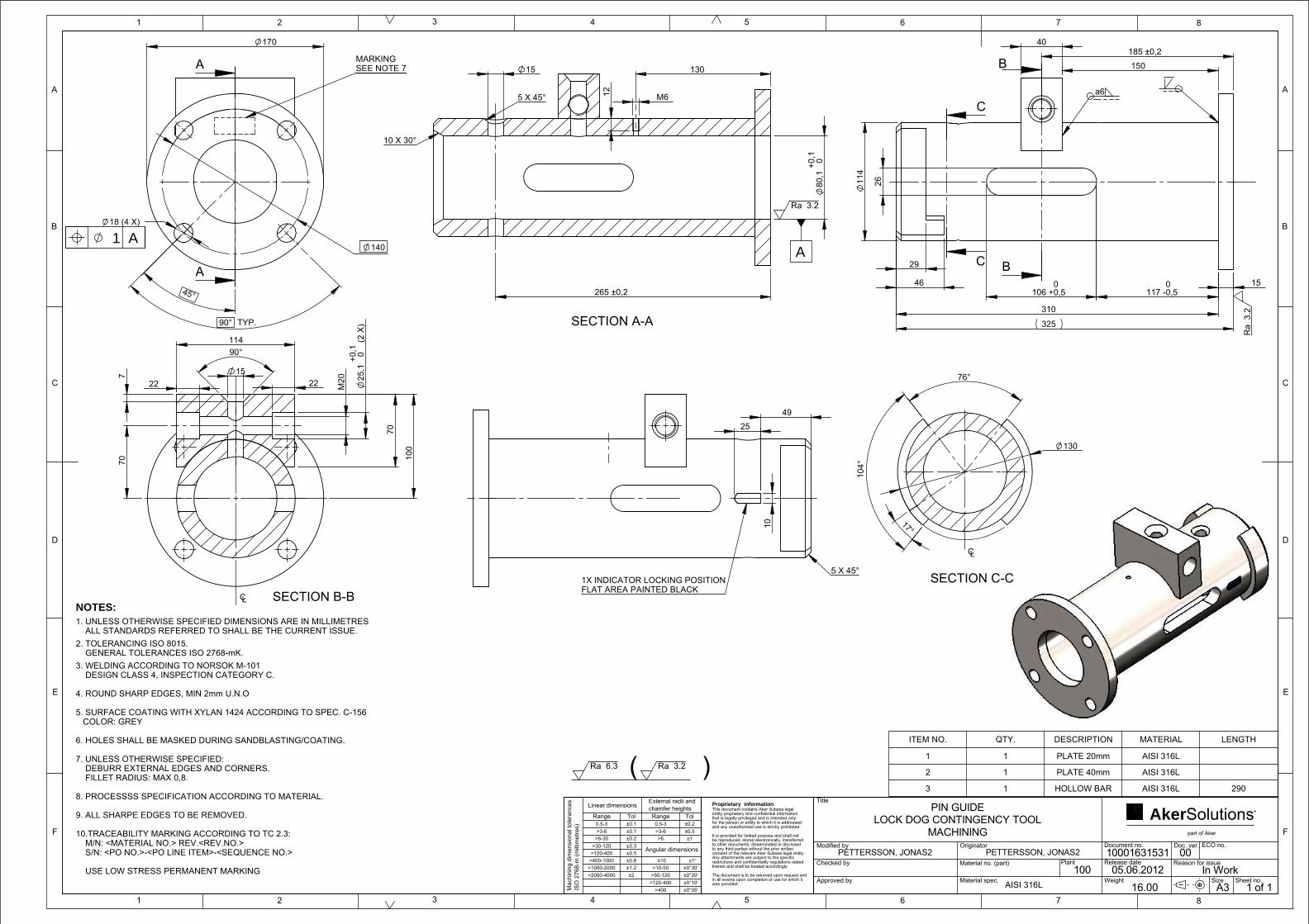
in all events upon completion of use for which it
Proprietary informationThis document contains Aker Subsea legal entity proprietary and confidential information that is legally privileged and is intended only for the person or entity to which it is addressed and any unauthorised use is strictly prohibited.
It is provided for limited purpose and shall not be reproduced, stored electronically, transferred to other documents, disseminated or disclosed to any third parties without the prior written consent of the relevant Aker Subsea legal entity. Any attachments are subject to the specific restrictions and confidentiality regulations stated therein and shall be treated accordingly.
The document is to be returned upon request and
was provided.
part of Aker
TMSolutionsAker
±0°10'
>1000-2000
Range
External radii andchamfer heights
Mac
hini
ng d
imen
sion
al to
lera
nces
ISO
276
8-m
(mill
imet
res)
Angular dimensions
Linear dimensions
Tol Range Tol0.5-3>3-6
>6-30>30-120
>120-400>400-1000
>2000-4000
±0.1±0.1±0.2±0.3±0.5±0.8±1.2±2
0.5-3 ±0.2±0.5±1
>3-6
≤10
>6
>10-50>50-120
>120-400>400
±1°±0°30'±0°20'
±0°05' A3In Work
0005.06.2012
10001631531
PETTERSSON, JONAS2
PETTERSSON, JONAS2
Title
Modified by
Checked by
Approved by
Originator
Material no. (part)
Material spec.
Document no.
Release date
Doc. ver.
Reason for issue
ECO no.
Size Sheet no.
PIN GUIDELOCK DOG CONTINGENCY TOOL
MACHINING
Plant100
Weight16.00
76°
17°
104
°
265 ±0,2
185 ±0,2
106 +
00,5 117
-00,5 45°
90° TYP.
25
SECTION C-C
CL
130
Ra 3.2
SECTION A-A
A
M6 12
130 15
5 X 45°
80
,1 + 0,
10
10 X 30°
a6
Ra
3.2
29
11
4
26
150
40
325
310
15 46
C
C B
B
SECTION B-BCL
70
7
22
114
15
90°
22
M20
(2 X
) 0
25
,1 + 0,
1
70
100
SEE NOTE 7MARKING
1 A140
170
18 (4 X)
A
A
1X INDICATOR LOCKING POSITIONFLAT AREA PAINTED BLACK
10
49
5 X 45°
( )Ra 3.2Ra 6.3
ITEM NO. QTY. DESCRIPTION MATERIAL LENGTH
1 1 PLATE 20mm AISI 316L
2 1 PLATE 40mm AISI 316L
3 1 HOLLOW BAR AISI 316L 290
USE LOW STRESS PERMANENT MARKING
C
B
A
1 2 3 4 8
D
5
E
F F
C
B
D
E
A
6 7
1 86 742 3 51 of 1
NOTES:
1. UNLESS OTHERWISE SPECIFIED DIMENSIONS ARE IN MILLIMETRES ALL STANDARDS REFERRED TO SHALL BE THE CURRENT ISSUE.
2. TOLERANCING ISO 8015. GENERAL TOLERANCES ISO 2768-mK.
3. WELDING ACCORDING TO NORSOK M-101 DESIGN CLASS 4, INSPECTION CATEGORY C.
4. ROUND SHARP EDGES, MIN 2mm U.N.O
5. SURFACE COATING WITH XYLAN 1424 ACCORDING TO SPEC. C-156 COLOR: GREY
6. HOLES SHALL BE MASKED DURING SANDBLASTING/COATING.
7. UNLESS OTHERWISE SPECIFIED: DEBURR EXTERNAL EDGES AND CORNERS. FILLET RADIUS: MAX 0,8.
8. PROCESSSS SPECIFICATION ACCORDING TO MATERIAL.
9. ALL SHARPE EDGES TO BE REMOVED.
10.TRACEABILITY MARKING ACCORDING TO TC 2.3: M/N: <MATERIAL NO.> REV.<REV.NO.> S/N: <PO NO.>-<PO LINE ITEM>-<SEQUENCE NO.>
AISI 316L

in all events upon completion of use for which it
Proprietary informationThis document contains Aker Subsea legal entity proprietary and confidential information that is legally privileged and is intended only for the person or entity to which it is addressed and any unauthorised use is strictly prohibited.
It is provided for limited purpose and shall not be reproduced, stored electronically, transferred to other documents, disseminated or disclosed to any third parties without the prior written consent of the relevant Aker Subsea legal entity. Any attachments are subject to the specific restrictions and confidentiality regulations stated therein and shall be treated accordingly.
The document is to be returned upon request and
was provided.
part of Aker
TMSolutionsAker
±0°10'
>1000-2000
Range
External radii andchamfer heights
Mac
hini
ng d
imen
sion
al to
lera
nces
ISO
276
8-m
(mill
imet
res)
Angular dimensions
Linear dimensions
Tol Range Tol0.5-3>3-6
>6-30>30-120
>120-400>400-1000
>2000-4000
±0.1±0.1±0.2±0.3±0.5±0.8±1.2±2
0.5-3 ±0.2±0.5±1
>3-6
≤10
>6
>10-50>50-120
>120-400>400
±1°±0°30'±0°20'
±0°05' A3In Work
0005.06.2012
10001631556
PETTERSSON, JONAS2
PETTERSSON, JONAS2
Title
Modified by
Checked by
Approved by
Originator
Material no. (part)
Material spec.
Document no.
Release date
Doc. ver.
Reason for issue
ECO no.
Size Sheet no.
LOCK PINLOCK DOG CONTINGENCY TOOL
MACHINING
Plant100
Weight16
38
SECTION B-B
15
5 x 45 TYP.
SECTION A-A63
R5 TYP.
49
R2 TYP.
20°
TY
P.
10°
USE LOW STRESS PERMANENT MARKING
C
B
A
1 2 3 4 8
D
5
E
F F
C
B
D
E
A
6 7
1 86 742 3 51 of 1
NOTES:
1. UNLESS OTHERWISE SPECIFIED DIMENSIONS ARE IN MILLIMETRES ALL STANDARDS REFERRED TO SHALL BE THE CURRENT ISSUE.
2. TOLERANCING ISO 8015. GENERAL TOLERANCES ISO 2768-mK.
3. UNLESS OTHERWISE SPECIFIED: DEBURR EXTERNAL EDGES AND CORNERS. FILLET RADIUS: MAX 0,8. SURFACE ROUGHNESS Ra3,2.
4. PROCESS SPECIFICATION ACCORDING TO MATERIAL.
5.TRACEABILITY MARKING ACCORDING TO TC 2.3: M/N: <MATERIAL NO.> REV.<REV.NO.> S/N: <PO NO.>-<PO LINE ITEM>-<SEQUENCE NO.>
AISI 1020, Cold Rolled
1
CL
53
453
R0,8
70
10 X 30°
143
80 j7 +-0,0180,012
25
B
B
A A
UNLESS OTHERWISE NOTEDRa 3,2
MARKING SEE NOTE 5
R3
183
40
THRU
5 X 45°
M20
163
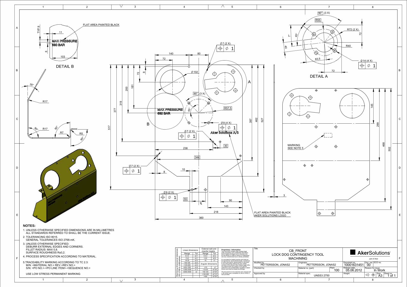
in all events upon completion of use for which it
Proprietary informationThis document contains Aker Subsea legal entity proprietary and confidential information that is legally privileged and is intended only for the person or entity to which it is addressed and any unauthorised use is strictly prohibited.
It is provided for limited purpose and shall not be reproduced, stored electronically, transferred to other documents, disseminated or disclosed to any third parties without the prior written consent of the relevant Aker Subsea legal entity. Any attachments are subject to the specific restrictions and confidentiality regulations stated therein and shall be treated accordingly.
The document is to be returned upon request and
was provided.
part of Aker
TMSolutionsAker
±0°10'
>1000-2000
Range
External radii andchamfer heights
Mac
hini
ng d
imen
sion
al to
lera
nces
ISO
276
8-m
(mill
imet
res)
Angular dimensions
Linear dimensions
Tol Range Tol0.5-3>3-6
>6-30>30-120
>120-400>400-1000
>2000-4000
±0.1±0.1±0.2±0.3±0.5±0.8±1.2±2
0.5-3 ±0.2±0.5±1
>3-6
≤10
>6
>10-50>50-120
>120-400>400
±1°±0°30'±0°20'
±0°05' A3In Work
0005.06.2012
10001631451
PETTERSSON, JONAS2
PETTERSSON, JONAS2
Title
Modified by
Checked by
Approved by
Originator
Material no. (part)
Material spec.
Document no.
Release date
Doc. ver.
Reason for issue
ECO no.
Size Sheet no.
CB_FRONTLOCK DOG CONTINGENCY TOOL
MACHINING
Plant100
Weight
(3 X)
45°
90°
R57,5
200
R55
45°
72
7°
(3 X)90°
72
83,5
30°
1 of 1 USE LOW STRESS PERMANENT MARKING
C
B
A
1 2 3 4 8
D
5
E
F F
C
B
D
E
A
6 7
1 86 742 3 5
NOTES:
1. UNLESS OTHERWISE SPECIFIED DIMENSIONS ARE IN MILLIMETRES ALL STANDARDS REFERRED TO SHALL BE THE CURRENT ISSUE.
2. TOLERANCING ISO 8015. GENERAL TOLERANCES ISO 2768-mK.
3. UNLESS OTHERWISE SPECIFIED: DEBURR EXTERNAL EDGES AND CORNERS. FILLET RADIUS: MAX 0,8. SURFACE ROUGHNESS Ra3,2.
4. PROCESS SPECIFICATION ACCORDING TO MATERIAL.
5.TRACEABILITY MARKING ACCORDING TO TC 2.3: M/N: <MATERIAL NO.> REV.<REV.NO.> S/N: <PO NO.>-<PO LINE ITEM>-<SEQUENCE NO.>
UNSS3 2750
A
1
1
CL
AKER SOLUTIONS LOGO
1
FLAT AREA PAINTED BLACK
1
1
B
7 (2 X)
140
397
527
8
517
377
8
143
80
7 (2 X)
72
238
360
30
218
102
344
55
9 (4 X) 462
10
319
181
7 (2 X)
72
90
9 (2 X)
DETAIL A
1
40
R40
R72 (2 X)
14 (4 X)
DETAIL B
FLAT AREA PAINTED BLACK
11 TY
P 9
6
103
MARKING SEE NOTE 5
299
468
145
502
3
R17
90°
90° R17 R7 R5
90°

in all events upon completion of use for which it
Proprietary informationThis document contains Aker Subsea legal entity proprietary and confidential information that is legally privileged and is intended only for the person or entity to which it is addressed and any unauthorised use is strictly prohibited.
It is provided for limited purpose and shall not be reproduced, stored electronically, transferred to other documents, disseminated or disclosed to any third parties without the prior written consent of the relevant Aker Subsea legal entity. Any attachments are subject to the specific restrictions and confidentiality regulations stated therein and shall be treated accordingly.
The document is to be returned upon request and
was provided.
part of Aker
TMSolutionsAker
±0°10'
>1000-2000
Range
External radii andchamfer heights
Mac
hini
ng d
imen
sion
al to
lera
nces
ISO
276
8-m
(mill
imet
res)
Angular dimensions
Linear dimensions
Tol Range Tol0.5-3>3-6
>6-30>30-120
>120-400>400-1000
>2000-4000
±0.1±0.1±0.2±0.3±0.5±0.8±1.2±2
0.5-3 ±0.2±0.5±1
>3-6
≤10
>6
>10-50>50-120
>120-400>400
±1°±0°30'±0°20'
±0°05' 2610.69 A3Created
0005.06.2012
10001631569
HOGLID, ERIK1
HOGLID, ERIK1
Title
Modified by
Checked by
Approved by
Originator
Material no. (part)
Material spec.
Document no.
Release date
Doc. ver.
Reason for issue
ECO no.
Size Sheet no.
CB_TOPLOCK DOG CONTINGENCY TOOL
Tie-In
Plant
Weight UNS S32750
583,5
243
57
185
29°
27
205
A
SEE NOTE 5MARKING
SHEET SEEN FROM UNDERNEATH
B
27
R17 (2X)
841
R17 (2X)
759
160
120
327
84
DETAIL A
25,2
28,8
39,6
43,2
54
25,
2
28,
8
39,
6
43,
2
54
R69(2X)
90°(2X)
DETAIL B
74
40
3
5
C
B
A
1 2 3 4 8
D
5
E
F F
C
B
D
E
A
6 7
1 86 742 31 of 2
NOTES:
1. UNLESS OTHERWISE SPECIFIED DIMENSIONS ARE IN MILLIMETRES ALL STANDARDS REFERRED TO SHALL BE THE CURRENT ISSUE.
2. TOLERANCING ISO 8015. GENERAL TOLERANCES ISO 2768-mK.
3. UNLESS OTHERWISE SPECIFIED: DEBURR EXTERNAL EDGES AND CORNERS. FILLET RADIUS: MAX 0,8. SURFACE ROUGHNESS Ra3,2.
4. PROCESS SPECIFICATION ACCORDING TO MATERIAL.
5. TRACEABILITY MARKING ACCORDING TO TC 2.3: M/N: <MATERIAL NO.> REV.<REV.NO.> S/N: <PO NO.>-<PO LINE ITEM>-<SEQUENCE NO.>
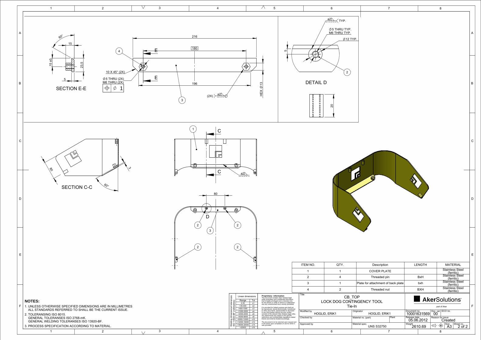
in all events upon completion of use for which it
Proprietary informationThis document contains Aker Subsea legal entity proprietary and confidential information that is legally privileged and is intended only for the person or entity to which it is addressed and any unauthorised use is strictly prohibited.
It is provided for limited purpose and shall not be reproduced, stored electronically, transferred to other documents, disseminated or disclosed to any third parties without the prior written consent of the relevant Aker Subsea legal entity. Any attachments are subject to the specific restrictions and confidentiality regulations stated therein and shall be treated accordingly.
The document is to be returned upon request and
was provided.
part of Aker
TMSolutionsAker
±14
Linear dimensions
±10
±16>16000-20000
>20000
Range
Wel
ding
dim
ensi
onal
tole
ranc
esIS
O 1
3920
-BF
(milli
met
res) Tol
2-30>30-400
>400-1000>1000-2000
>4000-8000>8000-12000
>12000-16000
±1±2±3±4±6±8
±12
>2000-4000
2610.69 A3Created
0005.06.2012
10001631569
HOGLID, ERIK1
HOGLID, ERIK1
Title
Modified by
Checked by
Approved by
Originator
Material no. (part)
Material spec.
Document no.
Release date
Doc. ver.
Reason for issue
ECO no.
Size Sheet no.
CB_TOPLOCK DOG CONTINGENCY TOOL
Tie-In
Plant
Weight UNS S32750
ITEM NO. QTY. Description LENGTH MATERIAL
1 1 COVER PLATE Stainless Steel (ferritic)
2 4 Threaded pin BxH Stainless Steel (ferritic)
3 1 Plate for attachment of back plate bxh Stainless Steel (ferritic)
4 2 Threaded nut BXH Stainless Steel (ferritic)
5
C
B
A
1 2 3 4 8
D
5
E
F F
C
B
D
E
A
6 7
1 86 742 32 of 2
NOTES:
1. UNLESS OTHERWISE SPECIFIED DIMENSIONS ARE IN MILLIMETRES ALL STANDARDS REFERRED TO SHALL BE THE CURRENT ISSUE.
2. TOLERANSING ISO 8015. GENERAL TOLERANSES ISO 2768-mK. GENERAL WELDING TOLERANSES ISO 13920-BF.
3. PROCESS SPECIFICATION ACCORDING TO MATERIAL.
1
a2
C
C
SECTION C-C
80
60°
3
2
2
3
2
2
D
80
2
DETAIL D
a2 TYP.
12 TYP.
5 THRU TYP.M6 THRU TYP.
5
1
3
4
a2(2X)
196
180
13
HE
X
5 THRU (2X)M6 THRU (2X)
216
10 X 45° (2X)
E
E
SECTION E-E
5
15
23,
5
60°
15
±0
20

in all events upon completion of use for which it
Proprietary informationThis document contains Aker Subsea legal entity proprietary and confidential information that is legally privileged and is intended only for the person or entity to which it is addressed and any unauthorised use is strictly prohibited.
It is provided for limited purpose and shall not be reproduced, stored electronically, transferred to other documents, disseminated or disclosed to any third parties without the prior written consent of the relevant Aker Subsea legal entity. Any attachments are subject to the specific restrictions and confidentiality regulations stated therein and shall be treated accordingly.
The document is to be returned upon request and
was provided.
part of Aker
TMSolutionsAker
±0°10'
>1000-2000
Range
External radii andchamfer heights
Mac
hini
ng d
imen
sion
al to
lera
nces
ISO
276
8-m
(mill
imet
res)
Angular dimensions
Linear dimensions
Tol Range Tol0.5-3>3-6
>6-30>30-120
>120-400>400-1000
>2000-4000
±0.1±0.1±0.2±0.3±0.5±0.8±1.2±2
0.5-3 ±0.2±0.5±1
>3-6
≤10
>6
>10-50>50-120
>120-400>400
±1°±0°30'±0°20'
±0°05' A3In Work
0005.06.2012
10001631538
HOGLID, ERIK1
HOGLID, ERIK1
Title
Modified by
Checked by
Approved by
Originator
Material no. (part)
Material spec.
Document no.
Release date
Doc. ver.
Reason for issue
ECO no.
Size Sheet no.
CB_BACKLOCK DOG CONTINGENCY TOOL
Tie-In
Plant100
Weight UNS S32750
354
ITEM NO. QTY. DESCRIPTION MATERIAL LENGTH
1 1 Flange for attachment Stainless Steel (ferritic) B*H
2 1 Back plate Stainless Steel (ferritic)
5
C
B
A
1 2 3 4 8
D
5
E
F F
C
B
D
E
A
6 7
1 86 742 31 of 1
NOTES:
1. UNLESS OTHERWISE SPECIFIED DIMENSIONS ARE IN MILLIMETRES ALL STANDARDS REFERRED TO SHALL BE THE CURRENT ISSUE.
2. TOLERANCING ISO 8015. GENERAL TOLERANCES ISO 2768-mK.
3. UNLESS OTHERWISE SPECIFIED: DEBURR EXTERNAL EDGES AND CORNERS. FILLET RADIUS: MAX 0,8. SURFACE ROUGHNESS Ra3,2.
4. PROCESS SPECIFICATION ACCORDING TO MATERIAL.
5.TRACEABILITY MARKING ACCORDING TO TC 2.3: M/N: <MATERIAL NO.> REV.<REV.NO.> S/N: <PO NO.>-<PO LINE ITEM>-<SEQUENCE NO.>
USE LOW STRESS PERMANENT MARKING
a2 TYP
1MARKINGSEE NOTE 5
1
55
3
25
75
10 9 (2 X)
15
CL
2
1
177
R55
28
70 80
7 (2 X)
R45
75
87
3
180
R77,5 (2 X)
35
285

in all events upon completion of use for which it
Proprietary informationThis document contains Aker Subsea legal entity proprietary and confidential information that is legally privileged and is intended only for the person or entity to which it is addressed and any unauthorised use is strictly prohibited.
It is provided for limited purpose and shall not be reproduced, stored electronically, transferred to other documents, disseminated or disclosed to any third parties without the prior written consent of the relevant Aker Subsea legal entity. Any attachments are subject to the specific restrictions and confidentiality regulations stated therein and shall be treated accordingly.
The document is to be returned upon request and
was provided.
part of Aker
TMSolutionsAker
±14
Linear dimensions
±10
±16>16000-20000
>20000
Range
Wel
ding
dim
ensi
onal
tole
ranc
esIS
O 1
3920
-BF
(milli
met
res) Tol
2-30>30-400
>400-1000>1000-2000
>4000-8000>8000-12000
>12000-16000
±1±2±3±4±6±8
±12
>2000-4000
A3Created
0005.06.2012
10001631458
HOGLID, ERIK1
HOGLID, ERIK1
Title
Modified by
Checked by
Approved by
Originator
Material no. (part)
Material spec.
Document no.
Release date
Doc. ver.
Reason for issue
ECO no.
Size Sheet no.
ROV HANDLELOCK DOG CONTINGENCY TOOL
Tie-In
Plant
Weight NORSOK M-120 Y05
115
90° (3X)
45°
100
150
180
280
60°
60°
63
1 of 1
C
B
A
1 2 3 4 8
D
5
E
F F
C
B
D
E
A
6 7
1 86 742 3 5
NOTES:
1. UNLESS OTHERWISE SPECIFIED DIMENSIONS ARE IN MILLIMETRES ALL STANDARDS REFERRED TO SHALL BE THE CURRENT ISSUE.
2. TOLERANSING ISO 8015. GENERAL TOLERANSES ISO 2768-mK. GENERAL WELDING TOLERANSES ISO 13920-BF.
3. PROCESS SPECIFICATION ACCORDING TO MATERIAL.
32
a2
1
1 9 (2X)
20
75
55
10
4
MARKINGSEE NOTE 5
1 9 THRU (4X)
4
a2
1
a2
2
160
90°
35
15
R20
5
10
3
B
90°
203
90°
128
R30 (4X)
DETAIL B
C C
20
ITEM NO. QTY. DESCRIPTION MATERIAL1 1 BRACKET FRONT NORSOK M-120 Y052 1 ROV HINGE NORSOK M-120 Y053 1 PIPE STRUCTURE NORSOK M-120 Y054 1 BRACKET BACK NORSOK M-120 Y05
SECTION C-C

in all events upon completion of use for which it
Proprietary informationThis document contains Aker Subsea legal entity proprietary and confidential information that is legally privileged and is intended only for the person or entity to which it is addressed and any unauthorised use is strictly prohibited.
It is provided for limited purpose and shall not be reproduced, stored electronically, transferred to other documents, disseminated or disclosed to any third parties without the prior written consent of the relevant Aker Subsea legal entity. Any attachments are subject to the specific restrictions and confidentiality regulations stated therein and shall be treated accordingly.
The document is to be returned upon request and
was provided.
part of Aker
TMSolutionsAker
±14
Linear dimensions
±10
±16>16000-20000
>20000
Range
Wel
ding
dim
ensi
onal
tole
ranc
esIS
O 1
3920
-BF
(milli
met
res) Tol
2-30>30-400
>400-1000>1000-2000
>4000-8000>8000-12000
>12000-16000
±1±2±3±4±6±8
±12
>2000-4000
A3In Work
0005.06.2012
10001631427
PETTERSSON, JONAS2
PETTERSSON, JONAS2
Title
Modified by
Checked by
Approved by
Originator
Material no. (part)
Material spec.
Document no.
Release date
Doc. ver.
Reason for issue
ECO no.
Size Sheet no.
BRACKETLOCK DOG CONTINGENCY TOOL
WELDMENT
Plant100
Weight
50
13
3
3
90°
2
MARKINGSEE NOTE 4
1
60
10 30
30 1
0
6 THRU (4X)
ITEM NO. QTY. DESCRIPTION MATERIAL
1 1 BRACKET AISI316L
2 2 BRACKET AISI316L
S/N: <PO NO.>-<PO LINE ITEM>-<SEQUENCE NO.>
C
B
A
1 2 3 4 8
D
5
E
F F
C
B
D
E
A
6 7
1 86 742 3 51 of 1
NOTES:
1. UNLESS OTHERWISE SPECIFIED DIMENSIONS ARE IN MILLIMETRES ALL STANDARDS REFERRED TO SHALL BE THE CURRENT ISSUE.
2. TOLERANSING ISO 8015. GENERAL TOLERANSES ISO 2768-mK. GENERAL WELDING TOLERANSES ISO 13920-BF.
3. PROCESS SPECIFICATION ACCORDING TO MATERIAL.
4. TRACEABILITY MARKING ACCORDING TO TC 2.3: M/N: <MATERIAL NO.> REV.<REV.NO.>
AISI 316L
a2 a2AA
SECTION A-A
17 TYP
30
6
2
M6 THRU5 THRU
HEX 10
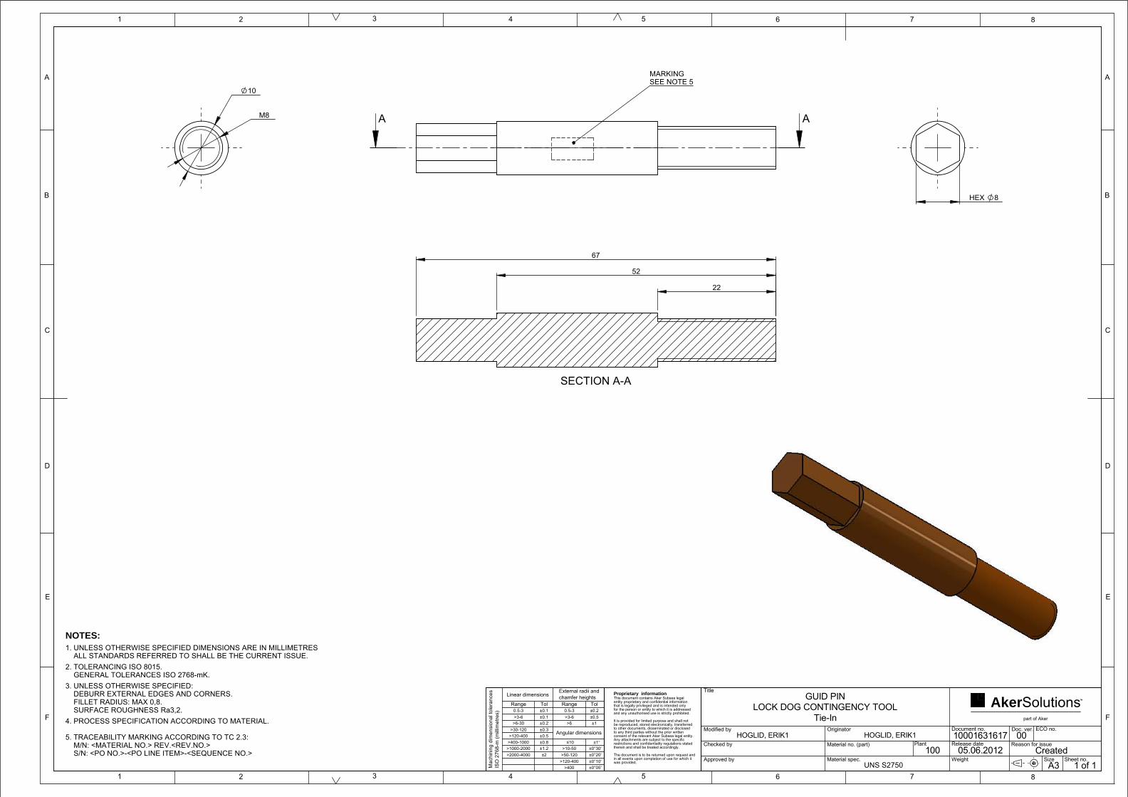
in all events upon completion of use for which it
Proprietary informationThis document contains Aker Subsea legal entity proprietary and confidential information that is legally privileged and is intended only for the person or entity to which it is addressed and any unauthorised use is strictly prohibited.
It is provided for limited purpose and shall not be reproduced, stored electronically, transferred to other documents, disseminated or disclosed to any third parties without the prior written consent of the relevant Aker Subsea legal entity. Any attachments are subject to the specific restrictions and confidentiality regulations stated therein and shall be treated accordingly.
The document is to be returned upon request and
was provided.
part of Aker
TMSolutionsAker
±0°10'
>1000-2000
Range
External radii andchamfer heights
Mac
hini
ng d
imen
sion
al to
lera
nces
ISO
276
8-m
(mill
imet
res)
Angular dimensions
Linear dimensions
Tol Range Tol0.5-3>3-6
>6-30>30-120
>120-400>400-1000
>2000-4000
±0.1±0.1±0.2±0.3±0.5±0.8±1.2±2
0.5-3 ±0.2±0.5±1
>3-6
≤10
>6
>10-50>50-120
>120-400>400
±1°±0°30'±0°20'
±0°05' A3Created
0005.06.2012
10001631617
HOGLID, ERIK1
HOGLID, ERIK1
Title
Modified by
Checked by
Approved by
Originator
Material no. (part)
Material spec.
Document no.
Release date
Doc. ver.
Reason for issue
ECO no.
Size Sheet no.
GUID PINLOCK DOG CONTINGENCY TOOL
Tie-In
Plant100
Weight UNS S2750
5
C
B
A
1 2 3 4 8
D
5
E
F F
C
B
D
E
A
6 7
1 86 742 31 of 1
NOTES:
1. UNLESS OTHERWISE SPECIFIED DIMENSIONS ARE IN MILLIMETRES ALL STANDARDS REFERRED TO SHALL BE THE CURRENT ISSUE.
2. TOLERANCING ISO 8015. GENERAL TOLERANCES ISO 2768-mK.
3. UNLESS OTHERWISE SPECIFIED: DEBURR EXTERNAL EDGES AND CORNERS. FILLET RADIUS: MAX 0,8. SURFACE ROUGHNESS Ra3,2.
4. PROCESS SPECIFICATION ACCORDING TO MATERIAL.
5. TRACEABILITY MARKING ACCORDING TO TC 2.3: M/N: <MATERIAL NO.> REV.<REV.NO.> S/N: <PO NO.>-<PO LINE ITEM>-<SEQUENCE NO.>
MARKINGSEE NOTE 5
AA
SECTION A-A
52
22
67
M8
10
HEX 8

in all events upon completion of use for which it
Proprietary informationThis document contains Aker Subsea legal entity proprietary and confidential information that is legally privileged and is intended only for the person or entity to which it is addressed and any unauthorised use is strictly prohibited.
It is provided for limited purpose and shall not be reproduced, stored electronically, transferred to other documents, disseminated or disclosed to any third parties without the prior written consent of the relevant Aker Subsea legal entity. Any attachments are subject to the specific restrictions and confidentiality regulations stated therein and shall be treated accordingly.
The document is to be returned upon request and
was provided.
part of Aker
TMSolutionsAker
A3Created
0005.06.2012
10001631707
PETTERSSON, JONAS2
10167265
PETTERSSON, JONAS2
Title
Modified by
Checked by
Approved by
Originator
Material no. (part)
Material spec.
Document no.
Release date
Doc. ver.
Reason for issue
ECO no.
Size Sheet no.
HYDRAUKIC_DIAGRAMLOCK DOG CONTINGENCY TOOL
DIAGRAM
Plant100
Weight
41 2
Z
R
3
IN
Item Qty Description Specification
1 1 Receptical
2 1 Hydraulic pressure reducer CV2
3 1 Hydraulic pressure booster HC2
4 1 Pressure Gauge
1 of 1
C
B
A
1 2 3 4 8
D
5
E
F F
C
B
D
E
A
6 7
1 86 742 3 5
NOTES:
1. UNLESS OTHERWISE SPECIFIED DIMENSIONS ARE IN MILLIMETRES ALL STANDARDS REFERRED TO SHALL BE THE CURRENT ISSUE.
2. PROCESS SPECIFICATION ACCORDING TO MATERIAL.

Appendix
Page 1
APPENDIX D OMM
OMM
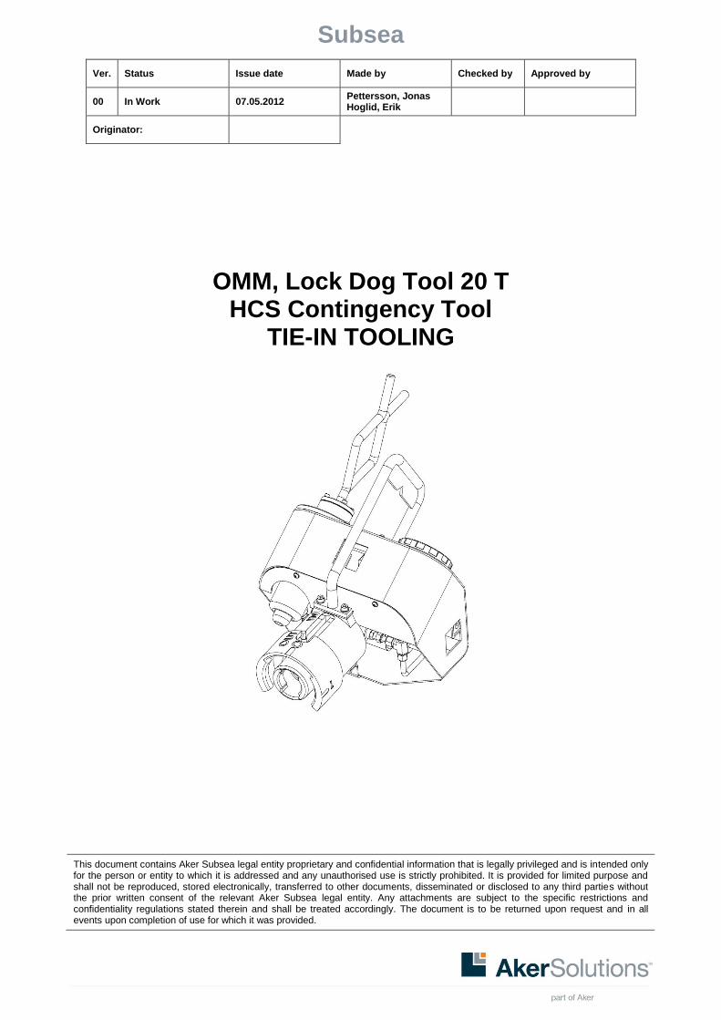
Subsea
Ver. Status Issue date Made by Checked by Approved by
00 In Work 07.05.2012 Pettersson, Jonas Hoglid, Erik
Originator:
This document contains Aker Subsea legal entity proprietary and confidential information that is legally privileged and is intended only for the person or entity to which it is addressed and any unauthorised use is strictly prohibited. It is provided for limited purpose and shall not be reproduced, stored electronically, transferred to other documents, disseminated or disclosed to any third parties without the prior written consent of the relevant Aker Subsea legal entity. Any attachments are subject to the specific restrictions and confidentiality regulations stated therein and shall be treated accordingly. The document is to be returned upon request and in all events upon completion of use for which it was provided.
OMM, Lock Dog Tool 20 T HCS Contingency Tool
TIE-IN TOOLING

Document: 10001631715
OMM, LOCK DOG TOOL 20T Version: 00 - In Work
HCS Issue date: 07.05.2012
TIE-IN TOOLING Page: 2 of 23
TABLE OF CONTENTS
1. INTRODUCTION ............................................................................................................................. 4
1.1. Purpose and Scope ......................................................................................................................... 4
1.2. Abbreviations ................................................................................................................................... 4
1.3. Contact Addresses .......................................................................................................................... 4
2. HEALTH, SAFETY AND ENVIRONMENT ..................................................................................... 5
2.1. General ............................................................................................................................................ 5
2.2. Safety Notes .................................................................................................................................... 5
2.2.1. Product Specific ............................................................................................................................... 5
3. TECHNICAL INFORMATION AND DATA ...................................................................................... 6
3.1. Technical Description ...................................................................................................................... 6
3.1.1. Main Components ............................................................................................................................ 7
3.1.2. Interface Description ........................................................................................................................ 8
3.2. Technical Data ................................................................................................................................. 8
3.3. Vessel Requirements ..................................................................................................................... 13
3.4. ROV Requirements ........................................................................................................................ 13
4. PACKING, PRESERVATION AND STORAGE INSTRUCTIONS ................................................ 14
4.1. Packing Instructions ....................................................................................................................... 14
4.2. Storage .......................................................................................................................................... 14
5. OPERATION.................................................................................................................................. 15
5.1. Installation and docking ................................................................................................................. 15
5.1.1. Installation/docking for retracting cylinder ..................................................................................... 15
5.1.2. Installation and docking for extending cylinder .............................................................................. 16
5.2. Normal Operation .......................................................................................................................... 18
5.2.1. Retracting cylinder ......................................................................................................................... 18
5.2.2. Extending cylinder ......................................................................................................................... 19
5.3. Release .......................................................................................................................................... 20
5.4. Recover .......................................................................................................................................... 20
5.5. Retrieval ......................................................................................................................................... 20
6. TROUBLESHOOTING .................................................................................................................. 21
7. INSPECTION, MAINTENANCE & REPAIR .................................................................................. 23
7.1. Corrective Maintenance ................................................................................................................. 23
7.1.1. Assembly and disassembly ........................................................................................................... 23
7.1.1.1. Assembly ....................................................................................................................................... 23

Document: 10001631715
OMM, LOCK DOG TOOL 20T Version: 00 - In Work
HCS Issue date: 07.05.2012
TIE-IN TOOLING Page: 3 of 23
7.1.1.2. Disassembly................................................................................................................................... 23
Document: 10001631715
OMM, LOCK DOG TOOL 20T Version: 00 - In Work
HCS Issue date: 07.05.2012
TIE-IN TOOLING Page: 4 of 23
1. INTRODUCTION
1.1. Purpose and Scope
The purpose of this manual is to give instructions to install, operate and maintain the following equipment as supplied by Aker Solutions.
Name Material No
Lock Dog Contingency Tool 20T HCS 10167265
1.2. Abbreviations
The following abbreviations are used in this document: HCS Horizontal Connection System HIC Hub Inspection Camera HPU Hydraulic Power Unit ROV Remotely Operated Vehicle LDCT Lock Dog Contingency Tool
1.3. Contact Addresses
Aker Solutions AS Rosenlundsplatsen 2
PO Box 2122 411 20
403 13 Gothenburg, Sweden
www.akersolutions.com

Document: 10001631715
OMM, LOCK DOG TOOL 20T Version: 00 - In Work
HCS Issue date: 07.05.2012
TIE-IN TOOLING Page: 5 of 23
2. HEALTH, SAFETY AND ENVIRONMENT
2.1. General
Safety is of prime importance when undertaking any work on or near the intervention tools. Only fully trained and suitably qualified personnel should work on the equipment and the prevailing site safety rules should always be fully adhered to.
2.2. Safety Notes
The following types of safety notes are used in this document:
Shall be used to highlight items/steps of special importance.
Shall be used to highlight items/steps that may result in damage on equipment.
Shall be used to highlight items/steps that may result in personnel injury or seriously damage on equipment.
2.2.1. Product Specific
Always wear suitable protective clothing and safety glasses when there is a possibility of contact with hydraulic oil.
This product has a pressure booster and operates with very high pressure when retracting cylinder. 680 Bar. Keep distance when pressurizing the tool.

Document: 10001631715
OMM, LOCK DOG TOOL 20T Version: 00 - In Work
HCS Issue date: 07.05.2012
TIE-IN TOOLING Page: 6 of 23
3. TECHNICAL INFORMATION AND DATA
3.1. Technical Description
The LDCT is a double acting hydraulic cylinder, operated by ROV and designed for connecting and separating in case of wedging of Aker Solutions installation tool using on horizontal connecting system. The LDCT has two connections points: One on the cylinder to connect to the installation tool and one on the rod to connect to the bolt. Those are designed to connect rod and cylinder in same time in one motion. The cylinder is handled and operated by a ROV, by using the handle on the LDCT. This ROV handle is hinged for use on the AKS 12’’ HCS. The hydraulic power to the cylinder is provided by the ROV. The interface between ROV and LDCT hydraulic system is based on a dual port hot stab with check valves to reduce leakage and water ingress. The hydraulic dual port receptacle is mounted on the LDCT and provided with Protection Stab for protection during transport and storage.

Document: 10001631715
OMM, LOCK DOG TOOL 20T Version: 00 - In Work
HCS Issue date: 07.05.2012
TIE-IN TOOLING Page: 7 of 23
3.1.1. Main Components
Main components with reference are listed below:
1. Pressure gauge
2. Dual port protection stab
3. ROV handle with hinge
4. Control box
5. Outer bayonet coupling
6. Double acting cylinder with bayonet coupling
7. Guide pin
Figure 3-1: Main components

Document: 10001631715
OMM, LOCK DOG TOOL 20T Version: 00 - In Work
HCS Issue date: 07.05.2012
TIE-IN TOOLING Page: 8 of 23
3.1.2. Interface Description
Table 1, Mechanical interfaces
Interface to Interface type
LDCT cylinder Bayonet coupling on LDCT and Installation tool
ROV ROV handle on the LDCT
Table 2, hydraulic interfaces
Interface to Interface type
ROV/HPU Dual Port Hot Stab, ISO 13628-8, Type A
3.2. Technical Data
Table 3, General data
Measurement Value
Operational force capacity Pull 20 metric tonnes (680 bar) Push 10 metric tonnes (200 bar)
Max. allowable water depth 3 000 m (10 000 ft)
Design life XX years
Operation temperature range 0 to + 50 oC
Input pressure 170-207 bar (2465 - 3000 psi)
Input flow 0-14 l/min (0 – 3.7 gal/min)
Maximum working Pressure retract (after booster)
680 bar (9860 psi)
Maximum working Pressure extend 200 bar (2900 psi)
Design Pressure hydraulic system 207 bar (3000 psi)
Check Valves In Dual Port Hot Stab / In Dual Port Receptacle
Hoses/ piping For subsea usage

Document: 10001631715
OMM, LOCK DOG TOOL 20T Version: 00 - In Work
HCS Issue date: 07.05.2012
TIE-IN TOOLING Page: 9 of 23
0
20000
40000
60000
80000
100000
120000
140000
160000
180000
200000
220000
0 25 50 75 100 125 150 175 200
FO
RC
E (
NE
WT
ON
)
INLET PRESSURE (BAR)
PRESSURE FORCE
EXTEND
RETRACT
Figure 3-2: Pressure table

Document: 10001631715
OMM, LOCK DOG TOOL 20T Version: 00 - In Work
HCS Issue date: 07.05.2012
TIE-IN TOOLING Page: 10 of 23
Figure 3-3 Envelope Lock Dog
Figure 3-4 Envelope (retracting of Installation Tool).
Figure 3-5 Envelope (extending of Installation Tool).
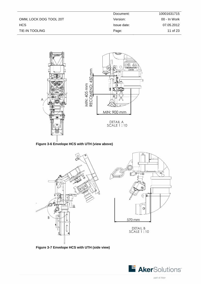
Document: 10001631715
OMM, LOCK DOG TOOL 20T Version: 00 - In Work
HCS Issue date: 07.05.2012
TIE-IN TOOLING Page: 11 of 23
Figure 3-6 Envelope HCS with UTH (view above)
Figure 3-7 Envelope HCS with UTH (side view)
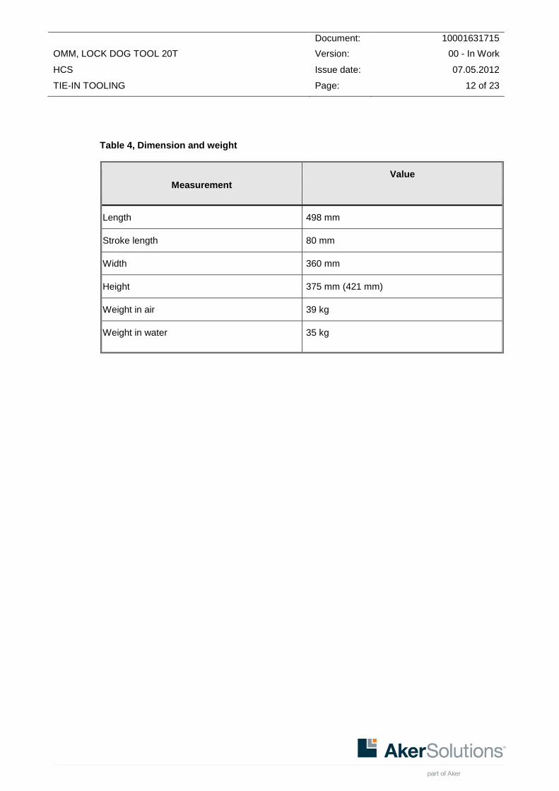
Document: 10001631715
OMM, LOCK DOG TOOL 20T Version: 00 - In Work
HCS Issue date: 07.05.2012
TIE-IN TOOLING Page: 12 of 23
Table 4, Dimension and weight
Measurement
Value
Length 498 mm
Stroke length 80 mm
Width 360 mm
Height 375 mm (421 mm)
Weight in air 39 kg
Weight in water 35 kg

Document: 10001631715
OMM, LOCK DOG TOOL 20T Version: 00 - In Work
HCS Issue date: 07.05.2012
TIE-IN TOOLING Page: 13 of 23
Table 5, Hydraulic data
Measurement Value
Hydraulic fluid Shell Tellus grade 22/ 32 or similar
Cleanliness of hydraulic fluid NAS class 8 or better
3.3. Vessel Requirements
No special requirements.
3.4. ROV Requirements
The following requirements apply for the ROV:
Arm for operating the tool.
Dual port hot stab, ISO 13628-8, Type A
Pressure and flow according to hydraulic requirement for tool.

Document: 10001631715
OMM, LOCK DOG TOOL 20T Version: 00 - In Work
HCS Issue date: 07.05.2012
TIE-IN TOOLING Page: 14 of 23
4. PACKING, PRESERVATION AND STORAGE INSTRUCTIONS
4.1. Packing Instructions
When packing the LDCT, make sure that:
It is placed in its dedicated transport box in such a way that unwanted movements are prevented; i.e. the LDCT should be secured by means of soft slings/ rope,
To avoid mechanical damage, the piston rod is in its retracted position,
To avoid ingress of unwanted objects, the protection stab is placed in the dual port receptacle.
4.2. Storage
Storage temperature: High storage temperature can cause damage to seals. The LDCT should be stored and transported in a non-corrosive environment.
Location: Indoor, in its transport box
Sunlight: Minimal.

Document: 10001631715
OMM, LOCK DOG TOOL 20T Version: 00 - In Work
HCS Issue date: 07.05.2012
TIE-IN TOOLING Page: 15 of 23
5. OPERATION
5.1. Installation and docking
5.1.1. Installation/docking for retracting cylinder
Figure 5-1 Position before connection to Installation Tool, typical (view above)
Figure 5-2 Position before connection with LDCT and Installation Tool.

Document: 10001631715
OMM, LOCK DOG TOOL 20T Version: 00 - In Work
HCS Issue date: 07.05.2012
TIE-IN TOOLING Page: 16 of 23
Step Description Date/Signature
1 Install the dual port hot stab into the LDCT dual port receptacle.
2 Fly the ROV with the LDCT to the HCS Installation Tool.
3 Extend the cylinder fully. The LDCT is now ready for installation/docking.
4 Before docking on Installation Tool, be sure that the handle on the Installation Tool is fully in lowered position.
5 Attach the LDCT into the designated connection on Installation Tool.
5.1.2. Installation and docking for extending cylinder
Figure 5-3 Position before connection to Installation Tool, typical (view above)

Document: 10001631715
OMM, LOCK DOG TOOL 20T Version: 00 - In Work
HCS Issue date: 07.05.2012
TIE-IN TOOLING Page: 17 of 23
Figure 5-4 Position before connection with LDCT and Installation Tool.
Step Description Date/Signature
1 Install the dual port hot stab into the LDCT dual port receptacle.
2 Fly the ROV with the LDCT to the HCS Installation Tool.
3 Retract the cylinder. The LDCT is now ready for installation/docking.
4 Before docking on Installation Tool, be sure that the handle on the Installation Tool is in fully vertical position.
5 Attach the LDCT into the designated connection on Installation Tool.

Document: 10001631715
OMM, LOCK DOG TOOL 20T Version: 00 - In Work
HCS Issue date: 07.05.2012
TIE-IN TOOLING Page: 18 of 23
5.2. Normal Operation
5.2.1. Retracting cylinder
Figure 5-5 Tool in typical operating position
Figure 5-6 Position of Guide Pin (1).
Step Description Date/Signature
1 Verify that the cylinder is fully extended before connection (position 2).
2 Connect the LDCT to Installation Tool by rotating the LDCT clockwise.
3 Verify that the LDCT has fully connected to installation tool and to the bolt.
4 Operate the LDCT to retract the cylinder fully(position 3).

Document: 10001631715
OMM, LOCK DOG TOOL 20T Version: 00 - In Work
HCS Issue date: 07.05.2012
TIE-IN TOOLING Page: 19 of 23
5.2.2. Extending cylinder
Figure 5-7 Tool in typical operating position
Figure 5-8 Position of Guide Pin (1).
Step Description Date/Signature
1 Verify that the cylinder is in the inner positions before connection(position 3)
2 Connect the LDCT to installation toll by
rotating the LDCT clockwise.
3 Verify that the LDCT has fully connected to installation tool and to the bolt.
4 Operate the LDCT to extend the cylinder fully(position 2).
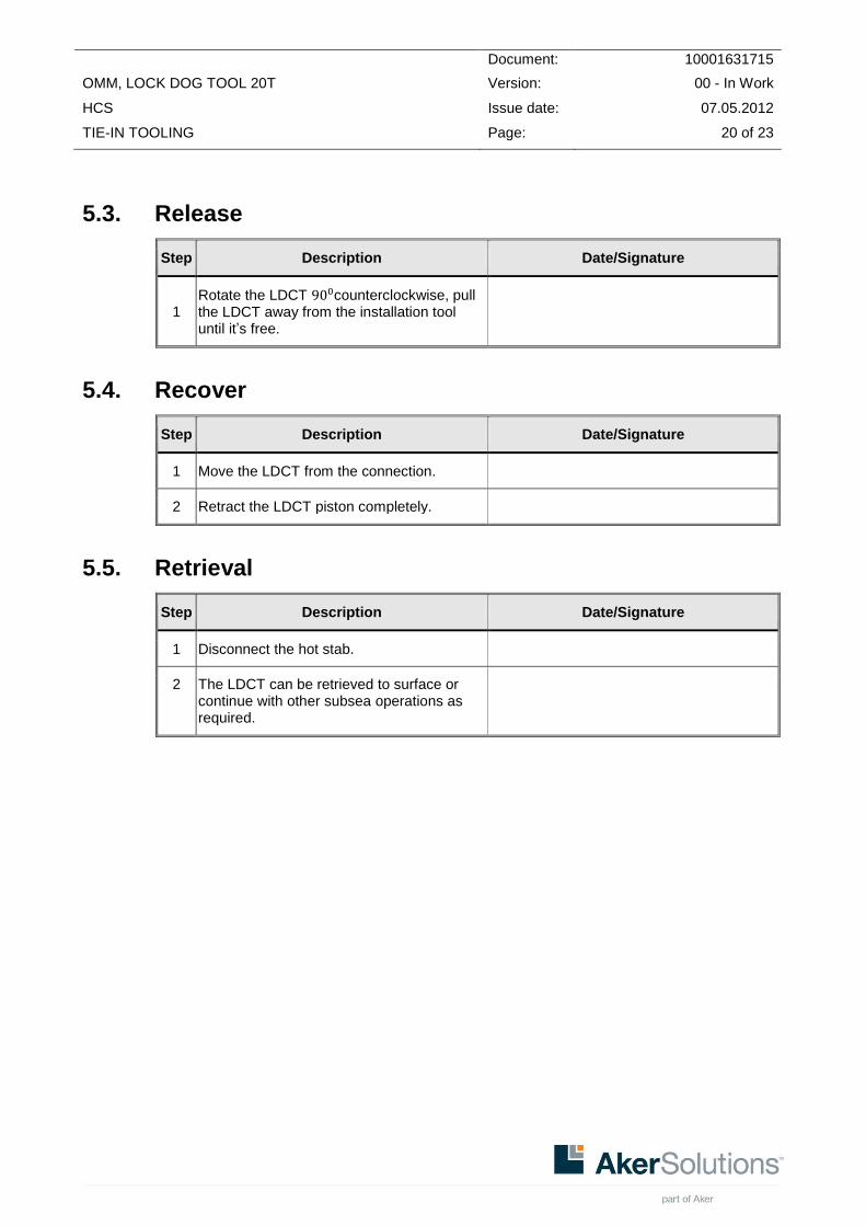
Document: 10001631715
OMM, LOCK DOG TOOL 20T Version: 00 - In Work
HCS Issue date: 07.05.2012
TIE-IN TOOLING Page: 20 of 23
5.3. Release
Step Description Date/Signature
1 Rotate the LDCT counterclockwise, pull the LDCT away from the installation tool until it’s free.
5.4. Recover
Step Description Date/Signature
1 Move the LDCT from the connection.
2 Retract the LDCT piston completely.
5.5. Retrieval
Step Description Date/Signature
1 Disconnect the hot stab.
2 The LDCT can be retrieved to surface or continue with other subsea operations as required.

Document: 10001631715
OMM, LOCK DOG TOOL 20T Version: 00 - In Work
HCS Issue date: 07.05.2012
TIE-IN TOOLING Page: 21 of 23
6. TROUBLESHOOTING
If you find any faults or exceptional wearing use the following list as a guidance for corrective maintenance.
Observation Possible cause Action
Dirt on piston rod Polluted environment Clean piston rod in extended position, apply hydraulic oil on stem
None, or jerky motion of piston rod
Contaminated oil Check oil quality (NAS class 8 or better)
System fault Check hydraulic medium supply (pressure according to specification)
Pipe burst Check oil supply
External damage on pipes Check pipe for damages/deformation
External damage on rod Check rod for damages/ deformations
Scratches in piston rod Contaminated oil Check oil quality (NAS class 8 or better)
Too large perpendicular forces Change operating conditions immediately Repair or replace piston rod Straighten up angle/ replace worn-out parts
Leakage from gland bushing Contaminated oil Check oil quality (NAS class 8 or better)
Too high piston speed Max. flow exceeds specification
Worn seals Seals to be replaced
Damage of gland bushing Replace together with seals
Damage of piston rod Replace together with seals
Leakage of hydraulic fluid Ruptured line Abort operation, retrieve ST to surface for repair
Not possible to retrieve LDCT from installed position on HCS installation tool.
ROV malfunction Retrieve ROV to surface for other troubleshooting/ faultfinding activities.
LDCT malfunction (ruptured line, bent piston rod, failed piston seal)
Cut hydraulic lines of ST to allow stroking by other means. Retrieve LDCT to surface for repair.

Document: 10001631715
OMM, LOCK DOG TOOL 20T Version: 00 - In Work
HCS Issue date: 07.05.2012
TIE-IN TOOLING Page: 22 of 23
LDCT will not install properly ROV inspection is required to find the cause of the problem. Remove the LDCT completely from its position and make a new attempt to install.

Document: 10001631715
OMM, LOCK DOG TOOL 20T Version: 00 - In Work
HCS Issue date: 07.05.2012
TIE-IN TOOLING Page: 23 of 23
7. INSPECTION, MAINTENANCE & REPAIR
7.1. Corrective Maintenance
7.1.1. Assembly and disassembly
7.1.1.1. Assembly
1. Assemble mini booster on control box.
2. Assemble back side of control box.
3. Assemble hot stab receptacle (Dual port system).
4. Assemble pressure gauge.
5. Assemble all hydraulic tubing and fittings.
6. Assemble upper part of control box.
7. Assemble front part of control box.
8. Assemble ROV handle.
Further assembly (piston rod, piston, seals) and maintenance of these parts should only be carried out by the manufacturer.
7.1.1.2. Disassembly
Carry out the above work steps in the opposite order.