local wind loads on roof-mounted solar energy systems · pressure equalisation. ... typical...
TRANSCRIPT

Local wind loads on roof-mounted solar energy systems
Geurts, C.P.W.; Bentum, van, C.A.
Published in:Recent advances in research on environmental effects on buildings and people
Published: 01/01/2010
Document VersionPublisher’s PDF, also known as Version of Record (includes final page, issue and volume numbers)
Please check the document version of this publication:
• A submitted manuscript is the author's version of the article upon submission and before peer-review. There can be important differencesbetween the submitted version and the official published version of record. People interested in the research are advised to contact theauthor for the final version of the publication, or visit the DOI to the publisher's website.• The final author version and the galley proof are versions of the publication after peer review.• The final published version features the final layout of the paper including the volume, issue and page numbers.
Link to publication
Citation for published version (APA):Geurts, C. P. W., & Bentum, van, C. A. (2010). Local wind loads on roof-mounted solar energy systems. In A.flaga, & T. Lipecki (Eds.), Recent advances in research on environmental effects on buildings and people (pp.195-206)
General rightsCopyright and moral rights for the publications made accessible in the public portal are retained by the authors and/or other copyright ownersand it is a condition of accessing publications that users recognise and abide by the legal requirements associated with these rights.
• Users may download and print one copy of any publication from the public portal for the purpose of private study or research. • You may not further distribute the material or use it for any profit-making activity or commercial gain • You may freely distribute the URL identifying the publication in the public portal ?
Take down policyIf you believe that this document breaches copyright please contact us providing details, and we will remove access to the work immediatelyand investigate your claim.
Download date: 30. May. 2018

LOCAL WIND LOADS ON ROOF-MOUNTED SOLAR ENERGY SYSTEMS
Chris P.W. Geurtsa,b, Carine A. van Bentumb
a Architecture Building and Planning, Eindhoven University of Technology, the Netherlands b TNO, Delft, the Netherlands, [email protected]
1. Introduction
The debate on climate change and its impact on the consequences on our living circumstances highlight the need for measures to mitigate the causes and to adapt to possible changes in climate. The production of renewable energy is undoubtedly one of the key solutions, not only for the climate change problem, but also for the oncoming scarcity of fossil fuels. Solar energy systems transform the solar radiation into either hot water (solar thermal systems), or electricity (photovoltaic systems or PV systems). Applications of these systems on or nearby buildings provide a situation where energy production is very close to energy consumption, which is very efficient in terms of energy losses, and creates novel opportunities with respect to product development and ownership of produced energy. Solar energy systems can be found on flat and pitched roofs, or integrated in facades. These systems should be able to carry the wind loads, as any product applied in the building envelope. This paper uses a classification of solar energy systems mounted on pitched or flat roofs. The work is mainly based on research on photovoltaic panels; however, values given are generally valid for solar thermal systems as well, since both systems consist of plate like structures. Based on the knowledge available, guidance for design of these systems is provided, and directions for future work are presented.
2. Classification of systems Roof- or building-mounted solar energy systems, and in particular photovoltaic
systems, can be divided into two general categories. The term building-integrated photo-voltaics (BIPV) is used when PV panels are an integrated part of the building envelope. These panels often are multifunctional, e.g. they play a role as a rain screen. Building-added photo-voltaics (BAPV) is the term applied to PV panels which are placed on top of a roof, or attached to the roof and façade, not being a part of the building envelope, so these

Chris P.W. Geurts
systems only function as energy delivering device. In general, BAPV is applied when existing buildings are retrofitted with solar energy systems. BIPV is more often, but not exclusively, found in newly designed buildings.
Building integrated and building added PV increase the overall value of roofs and facades. This will, in general, induce an increasing risk, where risk is defined as probability of failure times consequences of failure. The wind loads are without doubt one of the main actions to consider, when dealing with these risks.
The wind loading on solar energy components is the result of a pressure difference over the products applied, usually plate like structures. The load is described by a peak dynamic pressure, e.g. defined in the Eurocode, and the aerodynamic coefficient, in case of solar energy systems represented by a net pressure coefficient cp,net. The peak dynamic pressure is usually taken at roof height. The aerodynamic coefficient depends on the following aspects:
• Shape, dimensions and lay out of the solar energy systems; • Shape and dimensions of the building on which the systems are mounted; • Location of the systems on the building; • Permeability of the layers of the building envelope.
The first three aspects determine the value for the pressure or force coefficients. The
fourth aspect determines the extent to which the net load on the outer layer is reduced by pressure equalisation. Current guidelines and codes do not give explicit values to account for these aspects. The values depend on the way PV systems are installed. With respect to the wind effects on solar energy systems, the category of BAPV can be divided into two classes. The first is probably the most relevant when related to the quantity of installed power: Solar systems on top of flat roofs, where the roofs usually are fully covered with solar energy systems. The solar energy systems are mounted on a substructure, which is held in place by either ballast or mechanical fixing. The second group is where (existing) pitched roofs, covered with e.g. roofing tiles or metal sheeting, are equipped with panels parallel to the roof. Typical examples of these solutions are provided in Figure 1.
Figure 1: typical examples of Building Added Photo Voltaics; left hand side: retrofit systems on
pitched roofs; right hand side: systems placed on a flat roof.

Wind loads on roof-mounted solar energy systems
The category of BIPV can also be divided into two classes: The first class is the group
of solutions where the PV is mounted as a permeable outer layer with a watertight inner layer. The other group are the solutions where the PV is an integral part of the outer layer. Typical examples of these solutions are given in figure 2.
Figure 2: typical examples of Building Integrated Photo Voltaics; left hand side: PV as integral part of outer layer; right hand side: PV installed above watertight layer.
In case of a product integrated in the roof of a building the following different situations
occur: • Roofs consisting of one, impermeable, skin; Examples are glass roofs, where solar
energy products are directly integrated. The loads are the same as for a glass roof without additional functions.
• Roofs consisting of one layer, which is water tight, but air permeable. Examples are roofs of attics or shelves with roofing tiles without under-roof .
• Roofs consisting of at least two layers, where the outer layer is air permeable, and the inner layer is impermeable (or has a permeability which is much less then the outer layer). An example is a roof with roofing tiles, and a under-roof , consisting of wooden panels or otherwise. Within this class, two subclasses are defined:
o the under-roof is stiff; o the under-roof is flexible.
• Roofs consisting of at least two layers where the outer layer is a flexible, airtight layer. Examples are flexible roof covering products, such as EPDM, bitumen and PVC. This type has two subclasses:
o the under-roof is air impermeable; o the under-roof is air permeable.
These situations should be dealt with by guidelines for the fixing of conventional roof covering products. The loads do not depend on the fact whether or not a solar energy system is present, and these situations are not discussed further in this paper.
For the other situations, specific values are lacking in our current generation of building

Chris P.W. Geurts
standards. These situations are described as follows: 1: BAPV on pitched roofs: Solar energy systems are attached to a building, without
being part of the roof covering. Usually a traditional roof is available with roofing tiles or metal sheeting. The solar energy products are mounted parallel to the roof surface. Rain water will drain between the panels towards the conventional roofing products. The aerodynamic coefficient of these products depends on the position on the building, distance between roof and solar systems and
2: The flat roof systems where additional structures are made to carry solar energy systems. The pitch angle of these systems varies, and this depends on the targets for the solar energy production, but range between 0 (parallel to the roof) and 35 degrees for the north-western European countries.
3: Building Integrated products which fulfil also one or more of the traditional functions of the roof covering. These products usually form a permeable outer layer. In this case, the amount of pressure equalisation is relevant for design of fixings etcetera. These products are typically found in pitched roofs or facades.
In the next chapters, recent research results are given and proposals for guidelines are
presented. Missing knowledge is identified, so proposals for future work can be formulated.
3. Application of wind loading codes.
Current wind loading codes, e.g. the Eurocode EN 1991-1-4 [1], define wind loads as a dynamic pressure multiplied by one or more aerodynamic coefficients and by correction factors that account for effects like resonant response. The dynamic pressure contains the effect of wind statistics and terrain effects, and depends on geographical location, terrain roughness and height above ground. Different definitions of the dynamic pressure may be used, depending on averaging time and reference height. The aerodynamic coefficients depend on shape of the building and shape and dimensions of the structural element (e.g. solar energy system) under consideration. The aerodynamic coefficients in building codes are defined with respect to the definition of the dynamic pressure in the same code. Correction factors are applied to account for the effect of e.g. dynamic response. Finally, a partial safety factor is given. The expression of EN 1991-1-4 for the specification of the design value for the wind effect W is in case of net pressures:
dsnetppwdsnetpebwd cccqccczcvW ,,2 )(
2
1 γργ == (1)
In which: Wd is the design value for the wind effect, in this case the design net pressure over
a solar energy system; γw is the partial safety factor for wind loads, for which in the Eurocode national
choice is allowed;

Wind loads on roof-mounted solar energy systems
cp,net is the aerodynamic coefficient for net pressure; cs is a size factor, taking the lack of correlation of the wind pressures on a
building into account. Usually, this factor is equal to 1 for roof components, and will not be discussed further in this paper;
cd is the dynamic factor, taking the effects of resonance into account. This factor is explicitly defined for the overall load bearing structure of a building. For local loads, this factor is usually equal to 1, and this factor will not be discussed further in this paper;
ce is the exposure factor, in which the effects of terrain roughness are included; vb is the basic wind velocity, provided in the National Annexes to EN 1991-1-4; ρ is the density of air, with a value of about 1,25 kg/m3.
qp is 2
2
1be vc ρ is the peak dynamic pressure.
The peak dynamic pressure follows directly from the rules given in EN 1991-1-4. The
partial safety factor is defined in EN 1990, and national annexes need to give explicit values. Solar energy systems which are mounted on flat or pitched roofs can occur both as stand alone systems on dwellings as well as used in many rows on large roofs, so called solar energy plants. There is a large potential of both existing and new roofs. The wind loads are described with the following expression, following from Equation 1:
2, 2
1)( bnetpe vczcW ρ= (2)
For roofs and walls with multiple layers, pressure equalisation of the external pressures
may become important. In this paper, the pressure difference over the outer layer, where building integrated solar energy systems are mounted, is expressed by the external pressure coefficient cpe and a pressure equalisation factor ceq:
cp,net=cpeceq (3)
This pressure equalisation factor is defined as the ratio between the representative value
for the net wind induced pressure on the element under consideration and the representative value for the external wind induced pressure. This factor was defined initially in the Dutch code NEN 6702 [2]. EN 1991-1-4 gives rough guidance to account for this effect, but no specific values are given.
Values for cp,net, both for typical applications on flat roofs as well as pitched roofs, are not given in current building standards. Here general rules are derived, and some quantitative information on these coefficients is given. An extended overview of the wind loads on the classes of solar energy components is given in [3].
Chris P.W. Geurts
4. Systems placed on flat roofs Solar energy systems on flat roofs are usually placed on top of the waterproofing layer. Flat roof systems look like small canopy roofs mounted on top of buildings, mostly with an inclination towards the sun. Wind loading codes do not give any values specific for these cases. These systems cannot be treated as free standing canopies, since the effect of the building induced separation and reattachment, as well as effects of shielding by upstream rows, is not been taken into account in these standards. On the other hand, rules for flat roofs can not be used, since these structures are usually ventilated structures, and their position is lifted with respect to the roof, which may have a large effect on the net wind loads.
Wind tunnel experiments on solar energy systems have been carried out on project basis by many institutes the past decennia. Quite a number of these data have not been published for commercial reasons. A large group of experimental data comes from free standing structures, i.e. not mounted on a building. The results of such measurements only have a very limited applicability to roof mounted structures, because the effects of building induced turbulence caused by separation along the building edges is not included.
Only a few sensitivity studies on roof mounted systems have been published so far. Tieleman et.al. [4] presented an extensive wind tunnel study into the wind loads on solar-collector installations, mounted on various types of buildings. Measurements have been performed for collectors mounted on single family dwellings, with pitch roofs; for so-called berm units, for multi-row installations and for a solar attic house. Mean as well as peak pressure coefficients have been presented. Additionally, full scale measurements on a solar collector installed on a 30 degree pitch roof of an experimental building have been carried out. Local pressure coefficients for both the top and bottom surface of the solar collector as well as the local net pressure coefficients have been obtained, and have been well documented in the report. The data presented may serve as a valuable reference source for similar studies. It is concluded that the peak pressure coefficients are usually negative for inclinations of the solar collectors of less than 60 degrees. When the inclination is higher, positive peak coefficients may occur.
Radu and Axinte [5] presented model experiments on solar systems placed in rows on flat roofs. They investigated the applicability of area averaged pressure measurements, and measured the effects of different types of parapets. They found reductions of the force coefficients on the solar collectors until 45% of the coefficients found without parapets.
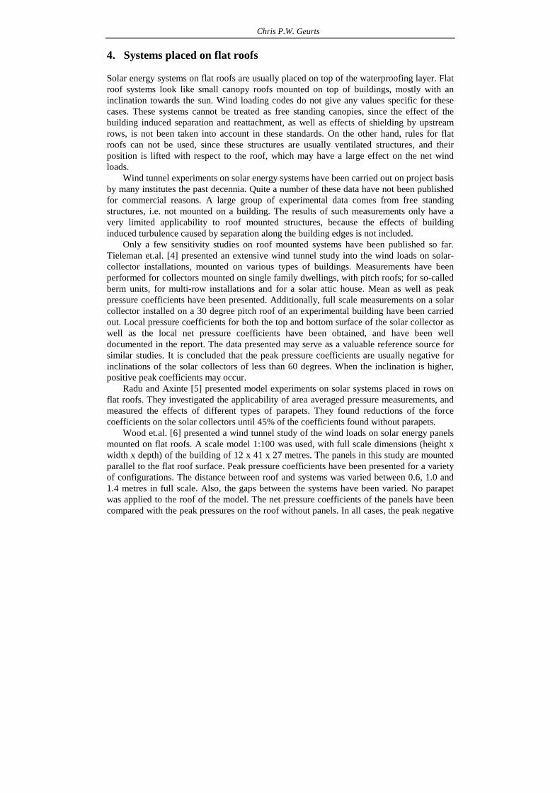
Wood et.al. [6] presented a wind tunnel study of the wind loads on solar energy panels mounted on flat roofs. A scale model 1:100 was used, with full scale dimensions (height x width x depth) of the building of 12 x 41 x 27 metres. The panels in this study are mounted parallel to the flat roof surface. Peak pressure coefficients have been presented for a variety of configurations. The distance between roof and systems was varied between 0.6, 1.0 and 1.4 metres in full scale. Also, the gaps between the systems have been varied. No parapet was applied to the roof of the model. The net pressure coefficients of the panels have been compared with the peak pressures on the roof without panels. In all cases, the peak negative

Wind loads on roof-mounted solar energy systems
net pressure coefficients found are lower than the peak pressure coefficients on top of the roof, even very close to the roof edges. However, the peak positive net pressure coefficients are significantly higher than the peak pressure coefficient for the roof without solar panels.
A study carried out by Geurts et.al. has been presented in detail in [7, 8]. The wind loads on solar energy systems on flat roofs have been studied on a model scale of 1:50 of a building with rectangular plan, with full scale height of 10 metres, width of 30 metres and depth of 40 metres. The roof of this building was divided into four quarters to make optimal use of symmetry. One of these quarters was not covered with solar energy systems, but with pressure taps in the roof, as a reference to compare the data with existing standards. Solar energy systems have been modelled with a dimension of 1,20 meters deep, and an inclination angle of 35 degrees. Both measurements on roofs with and without a parapet have been performed.
Values obtained so far have been used to define design rules for systems placed on flat roofs in the Netherlands and the UK [9, 10]. NVN7250 [9] gives cp,net values, as a function of position on the roof, and with and without the influence of parapets. The zones defined for the wind loads on flat roofs have been used for solar energy systems as well. The data given in this prestandard are given in tables 1 and 2. For systems with a small pitch, in table 1, values which are assumed safe have been applied. For this group of systems, when properly designed and detailed, pressure equalisation may reduce the overall loads. However, no explicit values are available to take this into account. For steeper systems, values from wind tunnel work have been taken and rounded off to conservative design values in table 2. Finally, table 3 provides values for the loads on systems with a closed substructure.
The values in NVN 7250 and BRE Digest 489 are based on the relatively limited amount of freely available data, and on safe assumptions. Therefore these data have limited applicability and may be uneconomic. There is a trend towards lower pitch angles for solar energy products on flat roofs, and the application on very large roofs is becoming increasingly popular, especially in countries with appropriate subsidies for large scale solar energy plants. Values for these systems have not yet been obtained explicitly, and are not given in the current guidelines. Knowing the wind load in detail would enable optimizing the structures with respect to material necessary for the structural safety.

Chris P.W. Geurts
Table 1: NVN 7250: Values for cp,net, solar energy systems on flat roofs with pitch angle lower than 10 degrees.
h/d2 ≤ 1 h/d2 ≥ 2 Roof zone uplift downward load uplift downward load
Corner -2,5 0,2 -2,0 0,2 r (edge) -2,0 0,2 -1,5 0,2 p (around attic) -1,2 0,6 -1,2 0,6 t (middle) -1,0 0,2 -1,0 0,2
Note 1: These values correspond to the external pressure coefficients for flat roofs in NEN 6702 and are assumed to be safe for this situation. No explicit experimental data are used to obtain this table.
Note 2: For 1 < h/d2 < 2 linear interpolation should be applied; h is building height; d2 is the smallest horizontal dimension of the building. Table 2: NVN 7250: Values for cp,net, solar energy systems on flat roofs with pitch between 10 and 40 degrees, and open substructure.
Roof parapet < 100 mm Roof parapet > 200 mm Roof zone uplift downward load uplift downward load
Corner -1,8 1,2 -1,5 1,0 Edges -1,6 1,2 -1,2 1,2 around attic -1,6 1,2 -1,2 1,2 Centre -0,6 0,6 -0,6 0,6 Centre, sheltered -0,4 0,4 -0,4 0,4
Table 3a: Values for cpe, for the upper surface of solar energy systems with closed substructure and pitch between 10 and 40 degrees. Roof Zone Roof parapet < 100 mm Roof parapet > 200 mm uplift downward load uplift downward load Corner -1,7 0,5 -1,7 0,5 Edges -1,6 0,5 -1,4 0,5 Centre -1,0 0,5 -1,0 0,5 Centre, sheltered -0,5 0,5 -0,5 0,5 Note 1: For intermediate heights of the roof parapet, linear interpolation should be applied. Note 2: The downward load includes a cpi = -0,3 to take the internal pressure within the substructure into
account.
Table 3b: Values for cpe, for the vertical surface of solar energy systems with closed substructure and pitch between 10 and 40 degrees. Roof Zone Roof parapet < 100 mm Roof parapet > 200 mm Underpressure Overpressure Underpressure Overpressure Corner -1,2 0,7 -1,2 0,7 Edges -1,1 0,5 -1,0 0,5 Centre -1,0 0,3 -1,0 0,3 Centre, sheltered -0,5 0,3 -0,5 0,3
Note 1: For intermediate heights of the roof parapet, linear interpolation should be applied.

Wind loads on roof-mounted solar energy systems
This raises new questions with respect to the wind loads and their effects. Besides the loads on the systems themselves, the amount of required ballast also increases the total vertical load on the underlying structure. Product development with respect to these systems focuses very much on decreasing the wind loads, thus not needing to apply additional ballast. Additionally, the horizontal component of the loads on the systems induces an additional horizontal load on the structure, relevant in the design of the overall stability of the building. Buildings with a large number of solar arrays may be loaded by an additional horizontal force in the same order of magnitude of the horizontal force found without solar energy systems. These effects should be carefully investigated, and an optimum between safety and economy should be realized.
Nowadays producers of substructures for solar energy aim to minimize the wind load on the systems and influence these loads by trying to equalize the loads over the panels, thus creating a very low net load.
Wind tunnel experiments are the most important technique to obtain design data. These experiments should be carried out carefully. The relevant requirements for testing are well known. For solar energy systems, the following requirements are relevant.
1: The solar energy system should be properly modelled in the experiment. When a full
scale experiment is performed (sometimes the product is simply placed in the wind tunnel), this usually is the case. When a scaled experiment is used, the effects of edge details, small joints and other openings should be considered and scaled properly.
2: All situations relevant for the design should be taken into account. This is partially subjective, but at least the following should be considered:
• Different angles of attack could be relevant and should be considered. • The effect of the building induced turbulence should be modelled properly for
roof mounted structures. • The flow effects on different positions on the roof should be known. Systems
placed near a corner experience other loads than systems placed in the centre of the roof.
• The effects of pressure equalisation through joints and vent holes should be modelled properly.
3: Wind loads should be based on analysis of extremes in pressures or forces, not on the means. Quasi steady theory can not be applied in the separation zones of roofs, since the building induced turbulence is dominating the velocity and pressure fields. Extremes in pressure could be much higher compared to the ones predicted from the means. Appropriate measurement and analysis should be based on theories such as defined by Cook.
4: when studying the resistance of the structure, the appropriate reliability levels should be considered. In Europe, these are defined in EN 1990, and especially the clauses on ‘design by testing’ are relevant. The evaluation of the strength of a structure usually requires a series of (destructive) tests, or a design calculation according to the codes for the structural material applied. A single test without failure does not include the information about the relevant failure mechanisms and scatter in structural strength.

Chris P.W. Geurts
The requirements for setting up and execution of wind tunnel experiments are given in various guidelines [11, 12, 13]. Requirements for the analysis of data are usually not given in these documents. Wind tunnel institutes apply their own procedures, and a general basis is lacking. Within the Netherlands, the wind tunnel institutes, checking authorities and structural engineers agreed to a guideline [11], in which strict rules for wind tunnel testing, including analysis methods and reporting requirements are given.
The above demands are not only valid for experimental work but also for numerical simulation by application of CFD. The requirement to base results on extremes is difficult to achieve with current CFD codes, and such claims require a thorough validation with experimental work. CFD may play a role in understanding phenomena, and for a first optimisation of the products, but the final check still needs proper experimental work.
Products are being advertised to withstand the wind loads without additional weight or fixing. Often these claims are based on simple experimental testing or numerical modelling and some of these claims are based on research results, which do not answer to all requirements for preparation, execution, analysis and application of wind tunnel experiments. Examples are experiments based on mean pressures instead of peak values; tests where building induced turbulence is not taken into account; and tests where only a few wind directions are considered. Usually, test reports supporting these claims are not freely available. A guideline for experimental determination of the wind loading on solar energy systems would help to increase the quality and to decrease storm damage to roof mounted structures.
5. Solar Energy Systems on pitched roof A frequently applied group of systems are the so-called retrofit systems for pitched
roofs. These systems are mounted by application of metal hooks to the under-roof, carrying the load through the roofing tiles. The solar energy systems are mounted parallel to the existing roofs, with a typical distance between roof and solar energy system in the order of 100 to 200 mm. An example is given in figure 2. The wind loads on these systems is related to the wind loads on the existing roof. However, near the corners and edges, such systems may be prone to extra wind loads due to local wind effects around these corners. These effects are not yet very well understood, and are not included in current codes and guidance.
Here, the values for the wind loading are also defined using expression 2. For this situation, current wind loading standards do not give values for cp,net. No experimental data are available. BRE Digest 489 [10] recommends using the following net pressure coefficients for modules in the central roof areas for the design of modules mounted above and parallel to pitched roofs:
Where the module is > 300 mm from the roof surface: - cp,net for wind uplift = -0.7 - cp,net for downward pressure = 1.0 Where the module is < 300 mm from the roof surface or where the space between the
roof and underside of the module is blocked or there is any possibility of it becoming blocked by leaves or other debris:
Wind loads on roof-mounted solar energy systems
- cp,net for wind uplift = -1.3 - cp,net for wind pressure = 1.0 These pressure coefficients are assumed valid for modules mounted in the central
regions of a pitched roof. If the module is close to the roof periphery (eaves, ridge or gable), the wind loads are likely to be significantly higher. No values are given for those situations. In current standards, this periphery has typically a width of about 1 meter.
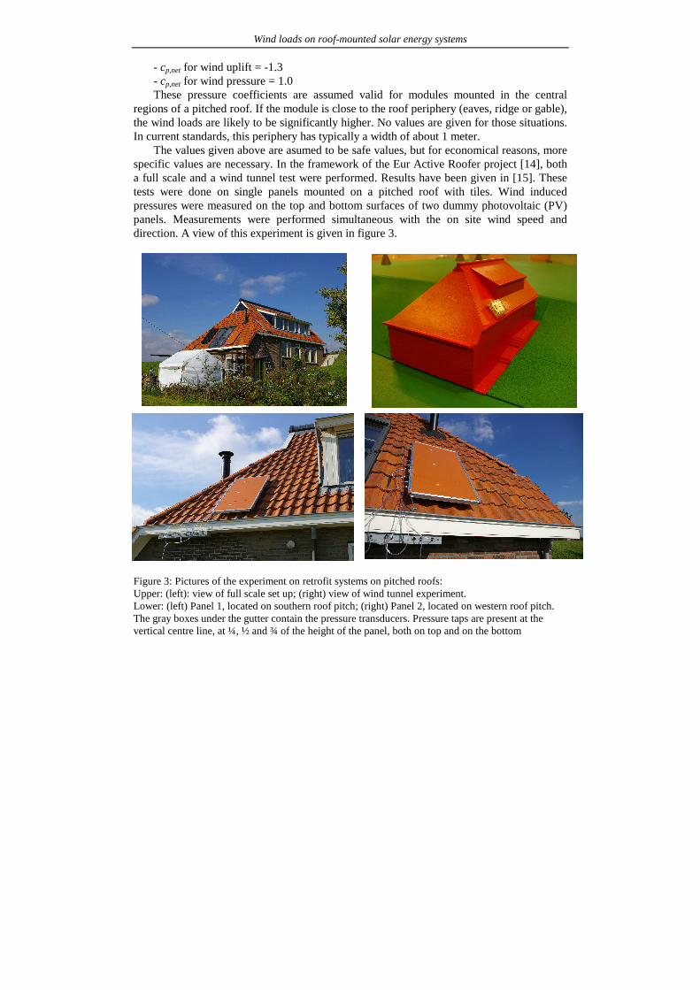
The values given above are asumed to be safe values, but for economical reasons, more specific values are necessary. In the framework of the Eur Active Roofer project [14], both a full scale and a wind tunnel test were performed. Results have been given in [15]. These tests were done on single panels mounted on a pitched roof with tiles. Wind induced pressures were measured on the top and bottom surfaces of two dummy photovoltaic (PV) panels. Measurements were performed simultaneous with the on site wind speed and direction. A view of this experiment is given in figure 3.
Figure 3: Pictures of the experiment on retrofit systems on pitched roofs: Upper: (left): view of full scale set up; (right) view of wind tunnel experiment. Lower: (left) Panel 1, located on southern roof pitch; (right) Panel 2, located on western roof pitch. The gray boxes under the gutter contain the pressure transducers. Pressure taps are present at the vertical centre line, at ¼, ½ and ¾ of the height of the panel, both on top and on the bottom

Chris P.W. Geurts
For the situation studied, values for cp,net in the order of -0,3 are found to be safe for uplift loading. These values indicate that a significant reduction of the loads can be found, compared to the current guidelines. However, this experiment does not cover all relevant situations, including effects of systems near the roof edges, different spacings between roof and solar energy systems and the application of multiple systems on a roof surface.
Solar energy systems can also be an integral part of the outer layer, thus replacing the conventional roof covering such as roofing tiles. Solar panels require ventilation underneath to prevent overheating, so these systems usually are mounted with a batten space, and gaps for ventilation. These gaps enable the wind induced pressures to equalize. In this way a relatively small pressure difference is found over the outer layer, i.e. the solar panel. Based on previous experience about roofing tiles, and a comparative experiment where the pressure differences over solar panels and roofing tiles have been measured, pressure equalisation coefficients, see equation 3, have been determined.
Figure 4: full scale experiment on solar panels integrated in tiled roofs. It was concluded that the differential pressures over the solar panels studied did not differ significantly from the differential pressures over conventional roofing tiles, provided that there is an airtight, stiff underroof and that the solar energy systems is not mounted in the edges and corner regions of the roof. The pressure equalisation coefficients as used in the Dutch National Annex for EN 1991-1-are used for these systems, which is equal to 0,33 for the central regions of the roof, so the net load over the systems is equal to 1/3 of the external pressures.
6. Concluding remarks Solar energy is becoming increasingly popular. The building sector provides large
potential surfaces for installation of both photovoltaic and solar thermal systems. The wind loads on these systems are the major design load.
Current guidelines for wind tunnel research provide useful directions how to carry out

Wind loads on roof-mounted solar energy systems
model tests. However, effects of very small details, including vent holes and open joints, can hardly be modelled on scale. A mix of measurements on a 1 to 1 scale, small model tests and possibly CFD simulations may be the way forward in the design of effectively wind resistant solar energy systems on roofs.
Values for roof mounted solar systems are available from some studies; however, these do not cover all aspects relevant in design. Only very few systematic studies are available to properly include values in design guidelines. Many project-based wind tunnel experiments are carried out, especially on flat roof systems, but unfortunately little knowledge is shared. The effects of building shape and dimensions, positioning on the roof, inclination relative to the roof, and the shape and dimensions of the systems under consideration are not yet fully known. These should all be considered to find the appropriate wind loads for a safe and economic design. Both wind tunnel and full scale measurements as well as CFD simulations are useful tools to find these values.
References
1. EN 1991-1-4: Eurocode 1: Actions on structures – General actions – Part 1.4: Wind actions, CEN, 2005
2. NEN 6702: Technical specifications for structures: Loads and Deformations, 2001 3. Geurts, C.P.W., Van Bentum, C.A., Wind Loads on Solar Energy Roofs, Heron, 54. 4. Tieleman, H.W., Akins, R.E. & Sparks, P.R., An Investigation of wind loads on solar
collectors, Report VPI-E-80-1, 1980, Virginia Polytechnic Institute and State University 5. Radu, A. and Axinte, E., Wind forces on structures supporting solar collectors, Journal
of Wind Engineering and Industrial Aerodynamics, 32 (1989) 93-100 6. Wood, G.S., Denoon, R.O., Kwok, K.C.S., Wind loads on industrial solar panel arrays
and supporting roof structure, Wind and Structures, vol. 4, no 6 (2001) p. 481-494 7. Geurts, C.P.W., Ravenshorst, G.J.P., Donkervoort, D.R., Windbelasting op
zonnecollectoren en zonnepanelen op plat-dak opstellingen: deelrapport experimentele bepaling van de ontwerp-windbelasting (in Dutch), TNO report 2002-BS-R0061 (available on request).
8. C.P.W. Geurts, C. van Bentum, P. Blackmore, Wind loads on solar energy systems, mounted on flat roofs, proceedings of 4EACWE, Prague, July 2005
9. NVN 7250: Solar energy systems-integration in roofs and facades – building aspects, NEN, July 2003. (under revision in 2011)
10. Blackmore, P., BRE Digest 489, Wind loads on roof-based photovoltaic systems, BRE, August 2004.
11. CUR Aanbeveling 103: Windtunnelonderzoek op (hoge) gebouwen en onderdelen ervan (in Dutch), 2005
12. ASCE Wind Tunnel Studies of Buildings and Structures (ASCE Manual and Reports on Engineering Practice), 1998
13. WTG Windkanalrichtlinie, WTG, Germany (in German) 14. EUR-ACTIVE-ROOFer, FP6 project.

Chris P.W. Geurts
15. C.P.W. Geurts, R.D.J.M. Steenbergen, Full scale measurements of wind loads on stand-off photovoltaic systems, proceedings of EACWE5, Florence, 2009
Acknowledgments Some of the work presented was based on research funded by SenterNovem (currently Agentschap NL). Other work was based on the results of the EU FP6 Project ‘Eur Active Roofer’