local storage meets local demand: a technical solution to
TRANSCRIPT

Local Storage Meets Local Demand: A Technical Solution to FuturePower Distribution System
Zhou, B., & Littler, T. (2016). Local Storage Meets Local Demand: A Technical Solution to Future PowerDistribution System. IET Generation, Transmission and Distribution, 10(3), 704-711. https://doi.org/10.1049/iet-gtd.2015.0442
Published in:IET Generation, Transmission and Distribution
Document Version:Peer reviewed version
Queen's University Belfast - Research Portal:Link to publication record in Queen's University Belfast Research Portal
Publisher rightsCopyright 2016 IET.This paper is a postprint of a paper submitted to and accepted for publication in IET Generation, Transmission & Distribution and is subjectto Institution of Engineering and Technology Copyright. The copy of record is available at IET Digital Library.
General rightsCopyright for the publications made accessible via the Queen's University Belfast Research Portal is retained by the author(s) and / or othercopyright owners and it is a condition of accessing these publications that users recognise and abide by the legal requirements associatedwith these rights.
Take down policyThe Research Portal is Queen's institutional repository that provides access to Queen's research output. Every effort has been made toensure that content in the Research Portal does not infringe any person's rights, or applicable UK laws. If you discover content in theResearch Portal that you believe breaches copyright or violates any law, please contact [email protected].
Download date:01. Feb. 2022

Local Storage Meets Local Demand: A Technical Solution to Future Power
Distribution System
Bowen Zhou
*, Tim Littler
School of Electronics, Electric Engineering and Computer Science, Queen’s University Belfast, Queen’s
University Belfast, Belfast, BT9 5AH, UK *[email protected]
Abstract: Future power systems are expected to integrate large-scale stochastic and intermittent
generation and load due to reduced use of fossil fuel resources, including renewable energy sources
(RES) and electric vehicles (EV). Inclusion of such resources poses challenges for the dynamic
stability of synchronous transmission and distribution networks, not least in terms of generation
where system inertia may not be wholly governed by large-scale generation but displaced by small-
scale and localised generation. Energy storage systems (ESS) can limit the impact of dispersed and
distributed generation by offering supporting reserve while accommodating large-scale EV
connection; the latter (load) also participating in storage provision. In this paper, a local energy
storage system (LESS) is proposed. The structure, requirement and optimal sizing of the LESS are
discussed. Three operating modes are detailed, including: 1) storage pack management; 2) normal
operation; and 3) contingency operation. The proposed LESS scheme is evaluated using simulation
studies based on data obtained from the Northern Ireland regional and residential network.
1. Introduction
Global reduction of fossil fuel reliance alongside carbon dioxide emission reduction has promoted
greater integration of renewable energy sources (RES) to meet demand targets and support changes in
electric power systems. One major area of development directly affecting power systems is transportation
electrification, which includes electric and hybrid road vehicles. It has been determined that in the UK, by
2020, there will be a total power demand of 35.3 GW with a planned installation of 17.9 GW of RES [1].
By the same year, it has also been estimated that in the UK there will be approximately 1.2 million battery
electric vehicles (BEV) and 0.35 million plug-in hybrid electric vehicles (PHEV) [2]. It can be concluded
that future UK power systems will require extensive integration of RES with conventional generation to
support normal domestic, commercial and industrial loads in addition to capacity for stochastic loads,
especially electric vehicles (EVs) and infrastructure, including energy storage.
Large-scale RES and large-scale EV can put pressure on transmission systems due to stochastic and
intermittent connection characteristics. RES generation power is obtained from natural resources, which is
of low controllability. On the contrary, EV charging and discharging power can be managed to meet
certain objectives such as load levelling, RES support, and emergency power supply. This is of significant
value for UK local distribution systems. More than 75% of the claimed RES by 2020 will be from
centralized or large power plants [1] while distributed generation (DG) (from embedded wind and solar
plant) will be less. For a small distribution network, the distributed RES capability cannot usually meet
local demand, especially if there is no external power supplier. Moreover, by taking into consideration EV
provision, the capacity situation is further aggravated.
Energy storage systems (ESS) facilitate control of power system stability [3], [4], power and energy
balancing [4]-[6] and RES provision [6], [7]. Due to the cost, lifetime, efficiency and variation in ESSs,
they are mainly installed at transmission level. However, if it is assumed that in the future these constraints
will be advanced or minimised, technical solutions for distribution level will emerge, thus providing local
storage to meet local demand. In other words, with RES and ESS provision, local solutions for local
problems will be feasible. This is of particular importance to EVs.
For a simple two terminal system, an ESS is conventionally installed at the sending end (feeder) to
stabilise output. This is the most likely choice for system operators at present because the system load,
showing a periodic feature, can be predicted accurately and maturely, and the only task is to control the
generation alongside load. However, future power systems will typically be defined by integration of
large-scale EV numbers and, to date, a viable solution to accurately predict EV charging demand has not
yet been proposed.
If ESS installation is considered at the receiving (load) end, both the stochastic feeder output and
demand can be omitted. Moreover, an ESS can also supply battery charging for EVs and emergency power
for local demand during contingency and preserve transmission and protection constraints.
In this paper, and with respect to EV charging and energy consuming processes, a local energy
storage system (LESS) is proposed. Section II firstly introduces the typical structure of LESS, and then
proposes the requirements and optimal sizing of the LESS. The optimal daily benefits of the LESS are also
discussed. Section III discusses three operating modes of the LESS scheme which are storage pack
management of the LESS, normal operation and contingency operation. The proposed LESS solution is
evaluated in the Northern Ireland power distribution network in Section IV, where a loss-of-load
evaluation is also proposed.
2. A LESS solution
The principle of a LESS solution is that local storage meets local demand. The basic concept is that
the original structure of the distribution grid remains the same while an ESS is added as the energy
supplier for EV charging as well as the emergency power supplier during contingencies. Detailed
information of the LESS solution is discussed as follow.
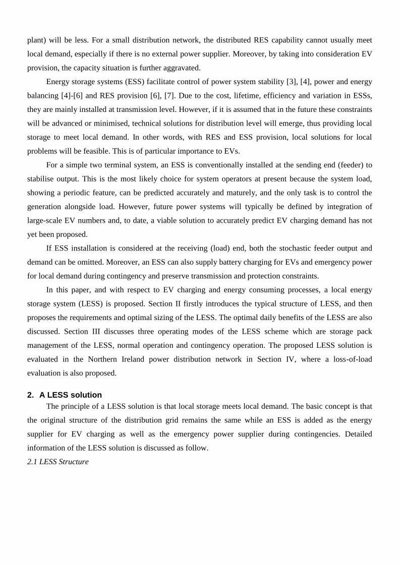
2.1 LESS Structure
There are three major parts in a LESS as shown briefly in Fig. 1. A LESS consists of ESS and local
RES and is divided into two levels.
System
Storage Packs
Transformer/Charger
Primary Level
Secondary Level
EVs
Transformer/Feeder
Residential Loads
RES
Fig. 1. Structure of the LESS solution
The primary level is connected directly with the system and it refers to the unit storage packs and
RES. There will be more than 2 packs in a single ESS. When one pack is being replenished (with charge)
by the system, the other packs can provide a non-interruptible charging service to local EVs.
The secondary level consists of the necessary support infrastructure, including transformers and
chargers to maintain the voltage level suitable for EV charging. In this paper, the EV discharging process
is neglected.
When the local distribution grid is disconnected from the power system during certain contingencies,
local storage and RES can still provide power and energy supply to local residential loads. Moreover, EVs
can also be charged at home through residential sockets.
2.2 Requirements for LESS
The requirements for LESS come from ESS itself, EVs RES and local residential loads.
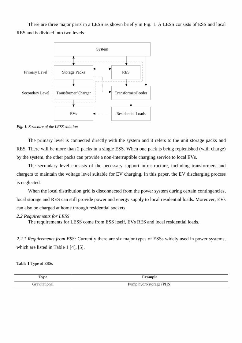
2.2.1 Requirements from ESS: Currently there are six major types of ESSs widely used in power systems,
which are listed in Table 1 [4], [5].
Table 1 Type of ESSs
Type Example
Gravitational Pump hydro storage (PHS)

Spatial Compressed air energy storage (CAES)
Kinetic Flywheel energy storage (FES)
Electric Capacity energy storage (CES)
Electromagnetic Superconducting magnetic energy storage (SMES)
Electrochemical Battery energy storage systems (BESS)
PHS, CAES and FES use mechanical subassemblies. During energy charging and discharging, this
kind of ESS is more severely limited by the upper and lower ramping limits [7]. In comparison with BESS,
CES and SMES both have lower energy density [4]. The advantages of BESS for applications are: high
energy density, high energy capability, round trip efficiency, cycling capability, life span, and initial cost
[4], [8]. Thus, BESS is a good option for the LESS scheme.
If cP and
dP are the rated charging and discharging power of the storage packs, then the power
capacity of the storage packs can be expressed as
max ,ESS c dP P P (1)
In this paper, power losses in the storage packs are neglected. It is also assumed that the charging
duration is usually longer than the discharging duration,
d cP P (2)
where, is a coefficient and 1 .
The rated energy capacity of the ESSESSE is
ESS ESS ESS ESS ESSE N P T (3)
where ESS is the energy capacity margin coefficient,
ESSN is the numbers of the storage pack andESST is the
charging duration. Usually ESSE will be several times larger than
ESS ESS ESSN P T since the batteries cannot be
fully discharged and there is a minimal level of the depth-of-discharge (DoD).
2.2.2 Requirements form EVs: EV charging demand is stochastic and intermittent. However, with practical
EV charging capacity forecasting, EV charging demand during each time interval can be obtained [6], [9].
The capacity of each unit storage pack should be larger than the maximum EV charging demand, which is
shown in (4).
maxd EVP P l (4)
where EVP l is the EV charging power at time l .

2.2.3 Requirements from RES: The net load of power systems increases significantly during the peak load
period when RES penetration decreases, which will cause a power shortage in power systems. Moreover,
abundant RES generation in valley load period can lead to a serious conflict with traditional generation [2],
[7]. A BESS has a rapid response speed and can relieve such problems. By taking into account
disconnected operation with the bulk power systems, the capacity of each unit storage pack should be
larger than the maximum RES generation power, which is shown in (5).
maxc RES LP P l P l (5)
where, RESP l is the RES generation power at time l and LP l is the load power at time l .
2.2.4 Requirements from Local Residential Loads: In the most severe condition, the local distribution grid
is disconnected to the power system due to a contingency. However, the LESS should be able to supply
power to the whole residential loads as well as EVs. Thus, the sum of the capacity of the LESS and the
RES power should be larger than the sum of the maximum EV charging demand and the peak of
residential loads during LESS discharging, which is shown in (6). And the capacity of the LESS should be
larger than the net generation power when RES power is abundant and LESS is under a charging mode,
which is shown in (7). However, due to financial constraints, the energy capacity of the LESS will not be
designed to cover 24-hour disconnected operation, which is limited by ESST .
max maxd RES EV LP P l P l P l (6)
maxc RES EV LP P l P l P l (7)
Taken into account (2) and the power flow constraintsPFP , (4) - (7) can be rewritten as
max ,
1max max , min
1max max
RES EV L
EV c PF
EV L RES
P l P l P l
P l P P
P l P l P l
(8)
2.3 Optimal Sizing of LESS
The rated power and capacity are the most important parameters for an ESS facility planning as they
directly influence system operation and consequently profit. In this paper, an economic cost-benefit model
is proposed to obtain the optimal sizing of a potential LESS scheme.
2.3.1 Object Function: The total cost includes the financial investment of ESS _c ESSS , RES _c RESS ,
transformers and chargers _c TS and other necessary equipment _c OS and the operation and maintenance cost

_c MS . The benefits include the operation income of the ESS _b ESSS and power supply income of the RES
_b RESS . Thus, the daily benefit of the LESS scheme, S can be obtained as follows,
_ _ _ _ _ _ _
b c
b ESS b RES c ESS c RES c T c O c M
S S S
S S S S S S S
(9)
where,
_
_ _
_ _ _
_ _ _
_
_
_
24 24
24
b ESS d d c c
l l
b RES RES o RES
l
c ESS ESS p ESS ESS e ESS
c RES RES i RES i
c T T ESS
c O O ESS
c M M ESS
S h P l h P lN N
S h P lN
S h P h E
S h P
S h P
S h P
S h P
(10)
and where N is the number of discrete time intervals; dh and
ch are the electricity selling price during
discharging and electricity purchasing price during charging of the ESS; _RES oh is the electricity selling price
of the RES; _ESS ph is the daily investment cost per unit power of the ESS; _ESS eh is the daily investment cost
per unit energy capacity of the ESS; _RES ih is the daily investment cost per unit power of the RES and _RES iP is
the total installed capacity of the RES; Th is the daily investment cost of the transformers and chargers in the
LESS; Oh is the daily investment cost of other necessary equipment in the LESS; and
Mh is the daily
operation and maintenance cost of the LESS.
2.3.2 Discussion of Daily Benefits: In (10), _c RESS can be regarded as a constant if _RES iP is fixed. _b RESS is
determined by the RES prediction or by records. Its value varies significantly, according to different
prediction methods. However, taking into account a static RES generation profile, _b RESS is determined by
the electricity selling prices in different time periods. _b RESS is also fixed if the electricity tariff is fixed. The
other parameters can be simplified as a linear term of cP or
dP if ESST is a constant. Thus, the object function
can be rewritten as,
cS DP C (11)
where
_ _ _ _ _
_ _
c b ESS c ESS c T c O c M
b RES c RES
DP S S S S S
C S S
(12)
and where C and D are the coefficients.
In (10), when 0S , the LESS scheme is considered economically beneficial, and when 0S , it is
considered that the LESS scheme is not worthy to be constructed. From (10)-(12) it can be concluded that
the daily benefit of the LESS scheme is mainly affected by the electricity tariff, EV charging profile and
the capacity of the ESS element used in the LESS scheme.
When the electricity tariff is high and the purchasing price low, the daily benefit is effectively higher
and thus beneficial; when the LESS capacity is small the total cost is also smaller, which is also beneficial;
the EV charging profile is obtained by capacity forecasting and the requirements for the LESS have to be
considered.
3. LESS operation
The proposed LESS will operate within three modes: 1) storage pack management; 2) normal
operation with the system connected; and 3) contingency operation with the system disconnected.
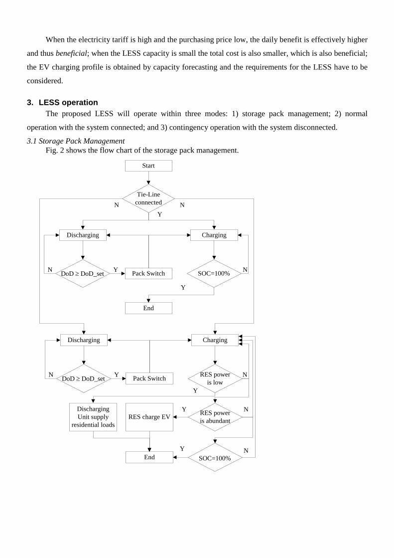
3.1 Storage Pack Management
Fig. 2 shows the flow chart of the storage pack management.
Start
ChargingDischarging
DoD DoD_setN
Pack SwitchY
SOC=100%N
End
Y
Tie-Line
connected
Y
ChargingDischarging
DoD DoD_setN
Pack SwitchY RES power
is low
N
End
Y
N N
Discharging
Unit supply
residential loads
RES power
is abundant
N
SOC=100%
Y N
RES charge EVY

Fig. 2. Flow chart of the storage pack management
The storage pack management has two parts: normal operation and contingency operation. When the
LESS is under normal operation mode, if DoD is smaller than the setting value, the discharging unit and
the charging unit will be switched. When the LESS is under contingency mode, the RES power should be
examined. When the RES power is low, the discharging unit should supply power to the residential loads,
which can be seen in (6). When the RES power is abundant, RES should be able to charge EVs, which can
also be seen in (7). After the charging unit is fully charged, it is ready to be switched to discharge.
3.2 Normal Operation Mode
When the LESS is connected to a bulk power system through a tie-line, the power direction will
either be from the LESS or to the LESS. Thus, the optimal object of the EV demand profile is tie-line
regulation. By considering the general model for EV capacity forecasting in [10], the transferred power
through the tie-line can be expressed as,
2
1
1min
d
S c t EV d
N
S S
ld
P l P l P l P l P l
z P l PN
2
1
min
1. .
0, 0, 1,
dN
S
l
d
z P l
f l g ls t
f l g l t N
(13)
where tP l is the tie-line transferred power without EVs or LESS at time l . SP is the mean level. z is the
objective function and f l and g l are the decision variables.
By considering (8), (9) and (13), the optimal size of the LESS, the daily benefit and EV charging
profile can be obtained.
3.3 Contingency Operation Mode
When the LESS is islanded, the prime task of the LESS is to maintain power supply and the second
task is to reduce RES power curtailment. Thus, the objective function is
2
1
1min
d
S c L RES EV d
N
S S
ld
P l P l P l P l P l P l
z P l PN
2
1
min
1. .
0, 0, 1,
dN
S
l
d
z P l
f l g ls t
f l g l t N
(14)

where, LP l is the gross demand without EVs at time l .
4. Case study
4.1 Parameters
Lisburn is the third largest city in Northern Ireland (N.I.) which is 9 miles away from Belfast city
centre. Many residents in Lisburn travel to Belfast during the Monday-Friday workdays making this city a
useful example to study large-scale EV usage and integration.
Based on the population and total EV numbers in the U.K., it is supposed that there will be 2280
BEVs and 660 PHEVs in Lisburn in 2020 [2]. Thus the charging power level is set to 7 kW for standard
charging [11]. The wind energy capacity is set to 20 MVA [1]. The power network structure of Lisburn
area is shown in Fig. 3.
Bus T
Bus L1
Bus L2
Bus L3Bus HT1
110/33 kV1
3
4
2
5
6
Load
EV
T2
110/33 kV
Fig. 3. The power network structure of Lisburn area
Based on historical data [12] and by taking into account improvements in energy efficiency and
‘Gone-Green’ scenarios [13], the projected daily winter load demand profile and the wind generation
power profile in Lisburn in 2020 are shown in Fig. 4

Fig.4. Lisburn winter load demand
Parameters for LESS sizing are listed in Table 2 and Table 3 [7], [14].
Table 2 Parameters of LESS
Symbol Value Symbol Value
2 ESS 1.5
ESSN 2 N 24
ESST 8 _ESS ph 25p/kW-d
_ESS eh 82p/MWh-d _RES ih 11p/kVA-d
Th 7 p/kW-d Oh 5 p/kW-d
Mh 8 p/kW-d
Table 3 Electricity tariff in different time periods
Time period Price (p/kWh)
1h 22:00-06:00 11
2h 06:00-08.00 13
3h 08:00-10:00, 18:00-21:00 17
4h 10:00-18:00, 21:00-22:00 14
_RES oh All day 15
0.00
20.00
40.00
60.00
80.00
00:00 06:00 12:00 18:00
Po
wer
(M
W)
Time (hour)
Lisburn Winter load
demand
Wind

4.2 Normal Operation Mode
The calculation results are shown in Fig. 5. The optimal sizing results are 24MWESSP and
576MWhESSE . The daily benefit of the LESS S is £-4,185.
Fig. 5. Simulation results under normal operation mode
In this mode, LESS discharging is considered to supply EV battery charging or local residential
loads only. Thus, only the negative part in Fig. 5 is optimised. From Fig. 5 it can be obtained that with EV
optimal charging, the deviation of the transferred power in the tie-line is reduced from 67MW to 44MW.
Inclusion of the LESS scheme improves local supply with a further reduction of 4MW; however there are
still fluctuations due to charging duration limit of the ESS.
The daily benefit is negative, meaning that under this condition or market circumstance, the LESS
scheme is not economically beneficial. There are two reasons. The first is that the incomes of RES
generation and ESS discharging are not too much and the ESS charging periods are mostly in the high
electricity price periods. In this study, electricity selling price is set as a constant. If it is also considered as
different in different time periods, the incomes might increase. The second reason is that the size of the
ESS is rather big.
4.3 Contingency Operation Mode
The optimal sizing results are 57MWESSP and 1368MWhESSE . The daily benefit S is £-31,324. This
is an unacceptable size for the ESS. The size is very large because of (6), using LESS to meet the
requirement from local residential loads.
-40.00
-20.00
0.00
20.00
40.00
00:00 06:00 12:00 18:00
Po
wer
(M
W)
Time (hour)
without EV or LESS
with EV
with LESS
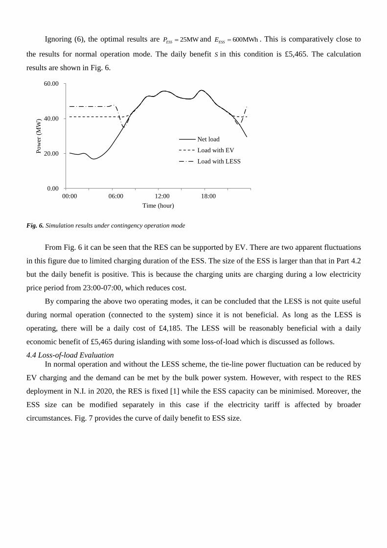
Ignoring (6), the optimal results are 25MWESSP and 600MWhESSE . This is comparatively close to
the results for normal operation mode. The daily benefit S in this condition is £5,465. The calculation
results are shown in Fig. 6.
Fig. 6. Simulation results under contingency operation mode
From Fig. 6 it can be seen that the RES can be supported by EV. There are two apparent fluctuations
in this figure due to limited charging duration of the ESS. The size of the ESS is larger than that in Part 4.2
but the daily benefit is positive. This is because the charging units are charging during a low electricity
price period from 23:00-07:00, which reduces cost.
By comparing the above two operating modes, it can be concluded that the LESS is not quite useful
during normal operation (connected to the system) since it is not beneficial. As long as the LESS is
operating, there will be a daily cost of £4,185. The LESS will be reasonably beneficial with a daily
economic benefit of £5,465 during islanding with some loss-of-load which is discussed as follows.
4.4 Loss-of-load Evaluation
In normal operation and without the LESS scheme, the tie-line power fluctuation can be reduced by
EV charging and the demand can be met by the bulk power system. However, with respect to the RES
deployment in N.I. in 2020, the RES is fixed [1] while the ESS capacity can be minimised. Moreover, the
ESS size can be modified separately in this case if the electricity tariff is affected by broader
circumstances. Fig. 7 provides the curve of daily benefit to ESS size.
0.00
20.00
40.00
60.00
00:00 06:00 12:00 18:00
Po
wer
(M
W)
Time (hour)
Net load
Load with EV
Load with LESS

Fig. 7. Curve of daily benefit to ESS size
This curve is a straight line showing downward trend since the daily benefit can be derived as a
linear equation of ESS size, as shown in (11) when the RES supply income is supposed to be a constant
due to certain generation profile. When there is no ESS, all the benefit comes from the electricity selling
income from RES. When the ESS size is smaller than 21MW, the LESS is beneficial with a minimum
daily income of £614.
In contingency operation mode, the power sources are RES and ESS and the power demand are
residential loads and EV charging demand. Fig. 8 provides the curve of loss-of-load to ESS size. In Fig. 8,
the lost power in the most severe condition is considered.
Fig. 8. Curve of loss-of-load to ESS size
-5000
0
5000
10000
15000
20000
25000
30000
35000
0 5 10 15 20 25
Dai
ly b
enef
it (
GB
P)
ESS size (MW)
-10.00
0.00
10.00
20.00
30.00
40.00
50.00
60.00
0 10 20 30 40 50 60
Lo
ss-o
f-lo
ad (
MW
)
ESS size (MW)

As the discussion in Part 4.4 and from Fig. 8, when the ESS size is smaller than 57MW, there is
loss-of-load. Therefore local supply cannot meet local demand since the generation in this network is
relatively small-scale. However, taking into account the daily benefit in both operating modes and the loss-
of-load, from (9) it can be derived that
tot lol lolS S h P (15)
where, totS is the total daily benefit;
lolh is the value of lost load (VoLL) [15], and lolP is the loss-of-load
expectation (LOLE) [16], [17]. Fig. 9 provides the total daily benefit with different ESS sizes under
different levels of loss-of-load cost.
Fig. 9. Total daily benefit with different ESS sizes under different levels of VoLL
It can be obtained from Fig. 9 that under different loss-of-load cost levels, the optimal LESS sizes to
make it sufficient for both operation modes are different. The crossing points in Fig. 9 refer to such sizes.
The critical point, which makes the total daily benefit positive, is close to the zero axis with the LESS size
to be 21MWESSP and 504MWhESSE , and the VoLL is £318/kW. The total benefit is £19 and the LESS is
sufficient to charge all EVs. With higher VoLL and larger LESS size, the total benefit per day will be less.
-15000
-10000
-5000
0
5000
10000
15000
20000
25000
30000
35000
0 5 10 15 20 25 30
Dai
ly b
enef
it (
GB
P)
ESS Size (MW)
Normal operation mode
10 GBP/kW
50 GBP/kW
100 GBP/kW
500 GBP/kW

However, based on the UK VoLL statistics [15], the VoLL is usually £10-20/kW, which is much
lower than the VoLL at the critical point. Taking into account such amount of VoLL, the optimal sizes of
LESS are listed in Table 4.
Table 4 LESS optimisation results under different levels of VoLL
VoLL (£/kW) ESSP (MW) ESSE (MWh) Daily benefit (£) EV support capability
10 1.1 26.4 32,448 <18.0%
20 2.16 51.84 30,753 <35.3%
From Table 4 it can be concluded that with smaller VoLL, the optimal size of ESS is smaller and the
total daily benefit is higher. The daily benefit mainly comes from the RES electricity sale income.
However, with smaller ESS size, EVs cannot be sufficiently charged by the proposed LESS solution. The
maximum percentages are about 18.0% under £10/kW VoLL and 35.3% under £20/kW VoLL.
5. Conclusions
This paper proposes ESS installation in the distribution system on the demand side in order to make
local supply provision to meet local demand. A technical solution, called LESS, is proposed and the
structure, requirements and optimal sizing of LESS have been presented. There are three operating modes
for the LESS solution: 1) storage pack management, 2) normal operation mode, and 3) contingency
operation mode. In the first mode, a flow chart of the storage pack management is provided. Tie-line
regulation and emergency power supply as well as RES support are respected for normal operation and
contingency operation, respectively. The proposed LESS is examined in real power distribution networks
in N.I. and a future scenario in 2020 is considered. The loss-of-load evaluation is also presented.
In the paper, it is demonstrated that local storage could practically meet local demand in any
perceived situation. During normal operation when the LESS is connected to the bulk power system, the
power fluctuation in the tie line can be reduced. During contingency operation when the LESS is
disconnected, the LESS is still powerful enough to support wind generation provision. Moreover, using
the LESS in a practical context for EV road vehicles, charging provision for intermittent and stochastic
connection (and disconnection) of vehicles is adequate without adverse impact on existing load. An
optimal LESS size for a local (city) distribution network has been presented with 21MWESSP and
504MWhESSE when the VoLL is £318/kW, and the total benefit is £19. With lower VoLL and smaller

LESS, the total benefit will increase. By considering an actual value of VoLL in the UK, the optimal size
of LESS is about1.1-2.16 MW while the maximum EV support capability is about 18.0-35.3%.
The economic benefits of the proposed LESS scheme vary, as presented in this case study. Three
areas of work in particular impact on the viability of the proposed scheme and are subject to ongoing and
further research: 1) different electricity selling tariff in different time periods, 2) LESS charging duration,
and 3) LESS sizes. The concept of a local storage scheme meeting local demand is better expressed during
islanding since it is economically beneficial under this condition. However, this may not be the case when
the local distribution system is connected to a bulk (transmission) power system. The LESS scheme is
proposed as a viable and effective scheme for future networks where a flexible electricity market will
operate using a purchase tariff that is available to a broad base of consumersAcknowledgment
This paper was supported by the Engineering and Physical Sciences Research Council (EPSRC)
UK-China joint research consortium (EP/F061242/1), the Science Bridge Award (EP/G042594/1),
Chinese Scholarship Council (CSC) and Queen’s University Belfast, UK.
6. References
[1] ‘Renewable Energy Roadmap UK Update 2013’,
https://www.gov.uk/government/uploads/system/uploads/attachment_data/file/255182/UK_Renewable_Energy_Roa
dmap_-_5_November_-_FINAL_DOCUMENT_FOR_PUBLICATIO___.pdf, accessed 22 January 2015
[2] Zhou, B.W., Littler, T., and Wang, H.F.: 'The impact of vehicle-to-grid on electric power systems: a review',
IET Renewable Power Generation Conference 2013, Beijing, China, September 2013, pp. 1-4
[3] Du, W., Wang, H.F., Cheng, S., Wen, J.Y., and Dunn, R.: 'Robustness of damping control implemented by
Energy Storage Systems installed in power systems', Int. J. Electr. Power Energy Syst., 2011, 33, (1), pp. 35-42
[4] Ribeiro, P. F., Johnson, B. K., Crow, M. L., Arsoy, A. and Liu, Y.: 'Energy storage systems for advanced
power applications', Proc. IEEE, 2001, 89, (12), pp. 1744-1756
[5] Ter-Gazarian, A. G.: 'Energy Storage for Power Systems'(IET Power and Energy Series 63, 2011, 2 edn. )
[6] Cai, H., Du, W., Yu, X. P., et al.: 'Day-ahead Optimal Charging/Discharging Scheduling for Electric
Vehicles in Micro-Grids', IET Renewable Power Generation Conference 2013, Beijing, China, September 2013, pp.
1-4
[7] Wang, S.Y., and Yu, J.L.: 'Optimal sizing of the CAES system in a power system with high wind power
penetration', Int. J. Electr. Power Energy Syst., 2012, 37, (1), pp. 117-125
[8] Divya, K. C., and Østergaard, J.: 'Battery energy storage technology for power systems—An overview',
Electric Power Systems Research, 2009, 79, (3), pp. 511-520
[9] Qian, K., Zhou, C., Allan, M., and Yuan, Y.: 'Modeling of load demand due to EV battery charging in
distribution systems', IEEE Trans. Power Syst., 2011, 26, (2), pp. 802-810

[10] Zhou, B.W., Littler, T., and Foley, A.: ' Electric Vehicle Capacity Forecasting Model with Application to
Load Levelling ', IEEE PES General Meeting 2015, Denver, CO, July 2015, pp. 1-5
[11] IEC 62196-2: 'Plugs, socket-outlets, vehicle connectors and vehicle inlets - Conductive charging of electric
vehicles - Part 2: Dimensional compatibility and interchangeability requirements for a.c. pin and contact-tube
accessories', 2011
[12] ‘System Demand’, http://www.eirgrid.com/operations/systemperformancedata/systemdemand/, accessed 22
January 2015
[13] ‘Electricity Capacity Assessment Report 2013’, https://www.ofgem.gov.uk/ofgem-
publications/75232/electricity-capacity-assessment-report-2013.pdf, accessed 22 January 2015
[14] Liu, Z., Wen, F., and Ledwich, G.: 'Optimal planning of electric-vehicle charging station in distribution
systems', IEEE Trans. Power Del., 2013, 28, (1), pp. 102-110
[15] ‘The Value of Lost Load (VoLL) for Electricity in Great Britain’,
https://www.gov.uk/government/uploads/system/uploads/attachment_data/file/224028/value_lost_load_electricty_g
b.pdf, accessed 22 January 2015
[16] Van Schijndel, A., Wetzer, J.M., Wouters, P.A.A.F.: ' Forecasting Transformer Reliability', 2006 IEEE
Conference on Electrical Insulation and Dielectric Phenomena, Kansas City, MO, October 2008, pp. 577-582
[17] Feng, D.: ' Life Expectancy Investigation of Transmission Power Transformers', Ph.D. thesis, University of
Manchester, 2013