loads acting on a semi-spade rudder - marine · pdf fileloads acting on a semi-spade rudder...
TRANSCRIPT

Second International Symposium on Marine Propulsors smp’11, Hamburg, Germany, June 2011
Loads Acting on a Semi-Spade Rudder
Andreas Brehm1, Volker Bertram
1, Ould El Moctar
1, 2
1 FutureShip GmbH – A GL company, Hamburg, Germany
2Universität Duisburg-Essen (UDE), Duisburg, Germany
ABSTRACT
This paper presents results of a research project wherein
the hydrodynamic loads acting on a semi-spade rudder of
an 8.500 TEU container vessel were investigated.
RANSE1 based CFD
2 simulations were carried out and
compared to full-scale and model-scale measurements.
Rudder cavitation prediction and a new rudder design to
minimise cavitation appearance was a main topic of the
project. The influence of cavitation and free-surface
modelling on the pressure distribution, and therefore on
the acting forces and moments was investigated.
Comparisons with measurements show that numerical
fluid and structure computations could be well used to
design and predict the loads acting on semi-spade rudders.
Keywords
Semi-Spade Rudder, Hydrodynamic Loads, Cavitation
1 INTRODUCTION
At the end of the last and the beginning of the new
century, the speeds of various ship types as well as the
propeller loadings had been increased. This had led to
higher structural loads and increased cavitation on
rudders. As a response to the increase in reported rudder
damage on large container vessels, Germanischer Lloyd
(GL) initiated a research project in 2005 focussed on the
hydrodynamics of semi-balanced rudders. The main
findings of this research project are presented in this
paper.
2 RESEARCH PROJECT
The research project, jointly conducted with SVA
Potsdam, was funded by the German Federal Ministry of
Economics and Technology. The project’s aims were to:
investigate the hydrodynamics and structural
loads on a large semi-balanced rudder, and
investigate the cavitation risks and how
moderate modifications may reduce cavitation
occurrence.
SVA Potsdam conducted a series of model tests within
the project. GL contributed its simulation experience:
1 Reynolds Averaged Navier-Stokes Equations 2 Computational Fluid Dynamics
first, the hydrodynamic loads were computed in a RANSE
approach; then, for selected cases, the loads were applied
to a finite element analysis (FEA) model and the
structural response of the rudder was computed. Based on
the insight gained, a new rudder design with significantly
reduced cavitation was developed.
We used full-scale measured rudder loads and cavitation
observations to validate model test and simulation results.
The test case was an 8.500 TEU container vessel, see
Table 1. Towards the end of the construction phase,
measuring devices to record the rudder loads and four
windows to observe in-service cavitation were installed.
Table 1: Main data of investigated ship
Ship
Length L > 300 m
Breadth B 40 m
Draft T 13 m
Design Speed v 25 kn
Power P 70.000 kW
Propeller
Diameter DP 9 m
Number of blades z = 6
Rudder
Type Semi-spade
Projected Rudder Blade Area ARB 75 m²
Projected Rudder Horn Area ARH 20 m²
3 VALIDATION
Numerous publications have shown the suitability of
RANSE simulations for hull, rudder and propeller flows
(Abdel-Maksoud et al 1998, Azcueta 2001, Streckwall et
al 2001, El Moctar 1997, 2001, 2002, 2004, Heinke et al
2004, Simonsen et al 2005, Hamann et al 2007, Brehm et
al 2007, 2009). Nevertheless, we conducted initial studies
for our test case and our RANSE method to investigate
the influence of boundary conditions and computational
control parameters on results.
3.1 Model-scale case
Steady RANSE simulations for the propeller in uniform
flow were compared to model tests in an open-water
diagram, see Fig. 1.

The rudder was investigated in uniform flow for angles
varying between 0° and 35° in steps of 5°. Figs. 2 and 3
compare measured drag and lift coefficients.
For this case, there were also model test results of the
Hamburg Ship Model Basin (HSVA). The measured
values differ between the two basins despite using the
same model. The RANSE results lie mostly between the
two measurements. Fig. 2 shows results from steady and
unsteady RANSE simulations. Fig. 3 shows the transient
RANSE results for the lift on the rudder blade alone and
on rudder blade and rudder horn. The forces on the rudder
horn cannot be measured in model tests. Therefore all
other figures compare only the forces on the rudder blade.
SVA Potsdam also conducted RANSE simulations for the
rudder in uniform flow. The results are included in the
figures.
Of the many model tests performed, we discuss here only
the measurement of the velocity field behind hull-
propeller and rudder in greater detail. SVA Potsdam
employed particle image velocimetry (PIV). For the
model test campaign, the PIV system was enhanced by a
stereoscopic camera allowing measurements of all three
velocity components in one plane.
The velocity field was measured near the rudder while the
ship model was towed with freely rotating propeller at
drift angles of 0° and 10° and various rudder angles.
There were two measurement campaigns. In the first
measurement campaign, four cross-section planes were
defined. One plane was between propeller and rudder, and
the other three planes behind the rudder, see Fig. 4. For
the second measurement campaign, a total of 28 planes
were investigated.
Figs. 5 to 10 compare exemplarily RANSE simulations
and PIV measurements for the measuring plane E1 for
rudder angles +20°, 0° and -20°. The velocity component
u (in longitudinal direction) was normalised with ship
speed ua. The agreement between simulations and model
tests was generally good.
3.2 Full-scale case
The grid for the RANSE simulations covered hull, rudder
and propeller. The conditions were taken as recorded
during the maiden voyage of the vessel. The model was
detailed enough to include all attachments to the rudder,
such as baffle plates and wedges. Fig. 11 compares the
cavitation extent as computed and as observed in full
scale.
The torsion and bending stresses at ship’s rudder stock
and horn were recorded by stress-strain gauges. The FEA
model was calibrated to the measuring system while the
vessel was dry docked, by applying a tensile force on the
rudder and measuring the stresses. The hydrodynamic
loads were determined in RANSE simulations. The
RANSE model covered hull, propeller and rudder and
used full-scale Reynolds numbers. The following
simplifications were applied:
No free surface deformation; instead a static
water column was imposed at the stern.
No ship hull motions
No cavitation model
No change in propeller rpm
The rudder was kept fixed at a given rudder angle,
varying between 0° and 35° in 5° steps. The periodical
loads at steps of 10° propeller turn were mapped to the
FEA model to compute the resulting stresses in the rudder
at the positions of the stress-strain gauges. The computed
stresses agreed satisfactorily with the full-scale measured
stresses, see Fig. 12.
Fig. 13 shows the FEA model used and the location of the
highest stresses.
The red lines in Fig. 14 show the time history of the
rudder stock moment and the rudder angle during a
35/35° zig-zag sea trial. The black lines show the time
histories of the RANSE simulation. The simulation
neglected ship motions, cavitation, free-surface
deformation and the change in propeller rpm. The rudder
was moved with the same rate of turn as observed in the
sea trial. The time histories of the rudder stock moment
are similar between sea trial and simulation, as long as the
ship has not started to turn. Then the moment histories
start to diverge. The most important factor for this
divergence should lie in the neglected ship motions.
Cavitation, change in propeller rpm and free surface
should play a minor role in this case. Further detailed
studies to quantify the effects of the assorted
simplifications are planned for 2011.
4 LOW-CAVITATION RUDDER DESIGN
Another goal of the project was the design of a rudder
with significantly lower cavitation. A constraint for the
new design was that only small modifications of the
original rudder design were permitted, excluding
specifically a change of rudder type (full-spade instead of
semi-spade rudder), twisted rudder, a shift of the
horizontal gap between horn and blade, a change of the
rudder area or shift of the rudder stock. The remaining
design freedom was limited to changes in the profile
shape and addition of small appendages. The design was
guided by 2D and 3D RANSE simulations.
In a first step, the original rudder was cut in three
horizontals planes, see Fig. 15. The original full profile
section in the cut A-A was investigated and improved
using the potential flow code XFOIL (Drela et al 2006).
The section was compared with assorted NACA profiles
and hybrid profile shapes stemming from previous SVA
Potsdam investigations (Heinke et al 2004). Then we
designed our own profile shape aiming at a small low-
pressure peak and a rather balanced pressure distribution
over the chord of the profile (Fig. 16), while not making
lift and drag coefficients worse.
The partition between horn and rudder for cuts B-B and
C-C leads to flow phenomena that cannot be captured by
XFOIL. Therefore, 2D RANSE simulations had to be

employed for these cuts. 28 gap variants were
investigated. Rudder angles were varied between 8° and
angles of attack between 6° and 28° in steps of 2°. In
total, more than 3000 RANSE simulations were
performed.
Streamlines were used for better assessment of gap
variants, see Fig. 17. Near the wall at the leading edge,
particles were selected and their paths visualised in order
to see whether the particles would enter the gap or not.
Increased flow through the gap means increased danger of
cavitation at the gap.
Based on the best 2D profile sections, a 3D model was
created and investigated. The RANSE simulations
included hull and propeller in the model. Only such
comprehensive models can capture appropriately the 3D
flow effects, which are vital for the correct assessment of
forces and moments at the rudder. Details of the rudder
sole have a significant impact on the rudder forces. The
first design (variant A) had a significantly curved forward
part, see Fig. 18. This noticeably reduced the cavitation
on the rudder blade. The low pressure gradient with
smooth transition between pressure and suction side
unfortunately also leads to lower lift forces on the profile
and therefore made variant A not acceptable.
Two further variants of the rudder sole were investigated:
Variant B had a curved forward part with much smaller
radius, variant C was fitted with an end plate instead of
rounding the forward part, see Fig. 18.
Rudder sole cavitation is induced by low-pressure regions
stemming from the fluid’s attempt to balance the pressure
difference between suction and pressure side by flowing
rapidly from one side to the other over the sole. The broad
end plate in variant C forces the major part of the flow
around the leading edge which was designed to be
particularly smooth to reduce cavitation. The end plate
also moderates the pressure regions from the rudder
surface to the outer edges of the plate on both sides. The
pressure difference is then balanced at the edges with
lower risk of cavitation, see Fig. 19.
Figs. 20 and 22 show the computed cavitation extent for
rudder angle 5° and 10° for original rudder and our new
design. The cavitation extent is significantly lower at
blade and vertical gaps in our new design. Cavitation is
not completely avoidable, due to the high velocities
involved. For our new design, significant cavitation
appears for rudder angles above 8°. However, most of the
time, rudder angles do not exceed 5° in real ship
operations.
For the new design, one constraint was that the lift forces
should not be lower than in the original design. This
condition was met, see Fig. 21. In fact, the lift forces were
improved: the original rudder featured a lift force of 278
kN at 0° rudder angle, while the new design featured only
12 kN. The new design was also better in terms of rudder
stock moments, see Fig. 23 While required stock moment
is higher between 0° to 20°, the maximum stock moment
is less than half of that of the original rudder. As the
maximum stock moment determines the size of the rudder
engine, this improvement has significant impact in
practice.
5 CONCLUSION
In the course of the presented research project, a
numerical procedure to calculate the hydrodynamic and
structural behaviour of semi-spade rudders has been
established. By including hull and propeller in the
numerical model, the flow around the rudder was
captured very realistically. Extensive model-scale and
full-scale tests allowed a successful validation of the
procedure.
Based on the original rudder, a new design with
significantly lower cavitation risk was developed.
Generally, numerical flow and structural analyses proved
to be powerful tools to support rudder design.
REFERENCES
Abdel-Maksoud, M., Menter F. R. & Wuttke, H. (1998).
‘Viscous flow simulations for conventional and high
skew propellers’. Ship Technology Research 45.
Azcueta, R. (2001). Computation of Turbulent Free-
Surface Flows Around Ships and Floating Bodies.
PhD Thesis, Technische Universität Hamburg-
Harburg.
Brehm, A. et al. (2007). ‘Berechnung von örtlich
auftretenden Extremlasten unter realistischen
Bedingungen (RELAX)’. BMBF-Report 03SX197A,
Technische Informationsbibliothek, Hannover.
Brehm, A. et al. (2009). ‘Hydrodynamische und
strukturmechanische Untersuchung von Rudern
großer, schneller Schiffe (XXL-Ruder)’. BMWI-
Report 03SX213A, Technische Informations-
bibliothek, Hannover.
Drela, M. et al. (2006). ‘XFOIL, Version 6.96’.
http://web.mit.edu/drela/Public/web/xfoil/,
Massachusetts Institute of Technology.
El Moctar, O. (1997). ‘Berechnung von Ruderkräftenʼ.
Institut für Schiffbau der Universität Hamburg
Bericht 582.
El Moctar, O. (2001). ‘Numerische Berechnung von
Strömungskräften beim Manövrieren von Schiffen’.
Technische Universität Hamburg-Harburg Bericht
611.
El Moctar, O. & Lindenau, O. (2002). ‘Kavitationsgefahr
bei Hydroprofilen’. HANSA 10.
El Moctar, O. (2004). ‘Numerical Prediction of
Hydrodynamic loads on rudders’. HANSA 7.
Hamann et al. (2007). ‘Entwicklung einer bruchmech-
anischen Prozedur (ProRepaS)’. BMBF-Report
03SX209A, Technische Informationsbibliothek,
Hannover.
Heinke et al. (2004). ‘Kavitationsarme Profile für
Hochleistungsruder’. BMWI-Report, Vorhaben 233
(03), Schiffbau- Versuchsanstalt Potsdam.

Simonsen, Claus D. & Stern, F. (2005). ‘RANS
Manoeuvring Simulation of Esso Osaka with Rudder
and Body-Force Propeller’. Journal of Ship Research
49(2), pp. 98–120.
Streckwall, H. & El Moctar, O. (2001). ‘RANS
Simulations for Hull, Propeller and Rudder
Interactions’. 4th Numerical Towing Tank
Symposium, Hamburg, Germany.
FIGURES
Propeller Open Water Test
0
0,1
0,2
0,3
0,4
0,5
0,6
0,7
0,8
0,9
0 0,1 0,2 0,3 0,4 0,5 0,6 0,7 0,8 0,9 1 1,1
J [-]
KT
, 1
0 K
Q,
Eta
_0
[-]
KT, Measurement 10 KQ, MeasurementEta_0, Measurement KT, CFD10 KQ, CFD Eta_0, CFD
Rudder Lift Coefficient CL
-0,05
0,05
0,15
0,25
0,35
0,45
0,55
0,65
0,75
0,85
0 5 10 15 20 25 30 35Angle [°]
CL
[-]
Measurement, SVA Measurement, HSVA
CFD, blade, SVA CFD, blade + horn, GL
CFD, blade, GL
Figure 1: Calculated and measured open-water diagram Figure 3: Calculated and measured rudder lift
Rudder Drag Coefficient CD
-0,05
0,00
0,05
0,10
0,15
0,20
0,25
0,30
0,35
0,40
0 5 10 15 20 25 30 35
Angle [°]
CD
[-]
Measurement, SVA Measurement, HSVA
CFD, SVA CFD, GL steady
CFD, GL transient
Figure 2: Calculated and measured rudder drag Figure 4: Locations of cross-sectional planes
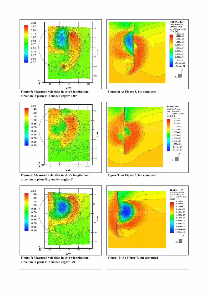
Figure 5: Measured velocities in ship’s longitudinal
direction in plane E1; rudder angle= +20°
Figure 8: As Figure 5, but computed
Figure 6: Measured velocities in ship’s longitudinal
direction in plane E1; rudder angle= 0°
Figure 9: As Figure 6, but computed
Figure 7: Measured velocities in ship’s longitudinal
direction in plane E1; rudder angle= -20
Figure 10: As Figure 7, but computed

Figure 13: FEA model (right) and location with highest
computed stress (left)
Figure 11: Cavitation clouds in full-scale observations (top)
and computed iso-surface with concentration of c=0.001
water vapour (bottom)
Figure 14: Time histories of full-scale measured (red) and
computed (black) rudder stock moments
Figure 12: Computed (red line) and measured (blue dots)
max. bending stress of rudder stock
Figure 15: 2D- investigated horizontal cuts
-60
-40
-20
0
20
40
60
80
-40 -30 -20 -10 0 10 20 30 40
Anstellwinkel [°]
Bie
gesp
an
nu
ng
[N
/mm
²]
Messung
Berechnung
Rudder angle [°]
Measured
Computed
Ben
din
g s
tre
ss
[N
/mm
2]

Figure 18: Geometrical variations of rudder sole
Figure 16: 2D- investigations with XFOIL: Run of the
pressure coefficient across the original profile (top) and
across one of the profile variations (bottom)
Figure 17: Streamlines of particles in the area of a gap;
original profile (top) and a profile variation (bottom)
Figure 19: Pressure distribution around rudder sole of
original rudder design (top) and around new design with
end plate (bottom)
New Design
Original Design

Figure 20: Pressure and cavitation (gray: iso-surface of a
VoF cav-concentration of 0.01) distribution for original
rudder design at 5° (top) and 10° (bottom) rudder angle
Figure 22: Pressure and cavitation (gray: iso-surface of a
VoF cav-concentration of 0.01) distribution at the new
rudder design at 5° (top) and 10° (bottom) rudder angle
Rudder blade + horn CY
-0,2
0
0,2
0,4
0,6
0,8
1
1,2
1,4
1,6
0 5 10 15 20 25 30 35
Angle [°]
CY
[-]
Origin design New design
Rudder blade CM
-0,1
-0,08
-0,06
-0,04
-0,02
0
0,02
0,04
0,06
0 5 10 15 20 25 30 35
Angle [°]
CM
[-]
Origin design New design
Figure 21: Transverse force coefficient of original and new
rudder design Figure 23: Rudder stock moment coefficient of original and
new design
Original Design New Design