lmms molybdenum disilicide coated htp-8 using arc- · pdf filesurface characterization of lmms...
TRANSCRIPT

.
Surface Characterization of LMMS Molybdenum Disilicide Coated HTP-8 Using Arc- Jet Hypersonic Flow David A. Stewart
March 2000
https://ntrs.nasa.gov/search.jsp?R=20040077277 2018-05-24T16:16:43+00:00Z

The NASA STI Program Office . . . in Profile
Since its founding, NASA has been dedicated to the advancement of aeronautics and space science. The NASA Scientific and Technical Information (STI) Program Office plays a key part in helping NASA maintain this important role.
The NASA STI Program Office is operated by Langley Research Center, the Lead Center for NASA's scientific and technical information. The NASA STI Program Office provides access to the NASA STI Database, the largest collection of aeronautical and space science STI in the world. The Program Office is also NASA's institutional mechanism for disseminating the results of its research and development activities. These results are published by NASA in the NASA STI Report Series, which includes the following report types:
TECHNICAL PUBLICATION. Reports of completed research or a major significant phase of research that present the results of NASA programs and include extensive data or theoreti- cal analysis. Includes compilations of significant scientific and technical data and information deemed to be of continuing reference value. NASA's counterpart of peer-reviewed formal professional papers but has less stringent limitations on manuscript length and extent of graphic presentations.
TECHNICAL MEMORANDUM. Scientific and technical findings that are preliminary or of specialized interest, e.g., quick release reports, working papers, and bibliographies that contain minimal annotation. Does not contain extensive analysis.
CONTRACTOR REPORT. Scientific and technical findings by NASA-sponsored contractors and grantees.
CONFERENCE PUBLICATION. Collected papers from scientific and technical confer- ences, symposia, seminars, or other meetings sponsored or cosponsored by NASA.
SPECIAL PUBLICATION. Scientific, technical, or historical information from NASA programs, projects, and missions, often concerned with subjects having substantial public interest.
TECHNICAL TRANSLATION. English- language translations of foreign scientific and technical material pertinent to NASA's mission.
Specialized services that complement the STI Program Office's diverse offerings include creating custom thesauri, building customized databases, organizing and publishing research results . . . even providing videos.
For more information about the NASA STI Program Office, see the following:
Access the NASA STI Program Home Page at http://www.sti.nasa.gov
E-mail your question via the Internet to help@ sti.nasa.gov
Fax your question to the NASA Access Help Desk at (301) 621-0134
Telephone the NASA Access Help Desk at (301) 621-0390
Write to: NASA Access Help Desk NASA Center for Aerospace Information 7121 Standard Drive Hanover, MD 21 076- 1 320
il! 8

Surface Characterization of LMMS Molybdenum Disilicide Coated HTP-8 Using Arc- Jet Hypersonic Flow David A. Stewart Ames Research Centel; Moffett FieM, California
c
National Aeronautics and Space Administration
Ames Research Center Moffett Field, California 94035- 1000

Available from:
NASA Center for Aerospace Information 7121 Standard Drive Hanover, MD 21076-1320 (301) 621-0390
National Technical Information Service 5285 Port Royal Road Springfield, VA 22161
(703) 487-4650

Surface Characterization of LMMS Molybdenum Disilicide Coated HTP-8 Using Arc-Jet Hypersonic Flow
.
DAVID A. STEWART
Ames Research Center
summary Surface properties for an advanced LockheedMartin Missile and Space (LMMS) molybdenum disilicide coated insulation ("-8) were determined using arc-jet flow to simulate Earth entry at hypersonic speeds. The catalytic efficiency (atom recombination coefficients) for this advanced thermal protection system was determined from arc-jet data taken in both oxygen and nitrogen streams at temperatures ranging from 1255 IC to roughly 1600 K. In addition, optical and chemical stability data were obtained from these test samples.
Nomenclature HT total enthalpy
hD enthalpy of formation
kW reaction rate constant
Le Lewis number
M molecular weight
Mf frozen Mach number
mf mass flow rate
P pressure
Pr Prandtl number
4 heat flux
R radius
s c Schmidt number
S arc length
T temperature
U velocity
a mass fraction
Y recombination coefficient
P viscosity
P density
3 gas constant
Subscripts 2
A
e
FF
1
N
0
0
W
00
behind bow shock wave
air
boundary-layer edge
flat-faced cylinder
chemical specie
nitrogen
oxygen
stagnation point
wall
free stream
Introduction Candidate thermal protection systems (TPS) that are being considered as part of the Access-to-Space program for future space launch vehicles, such as the Single Stage to Orbit and Space-lina 100, include metallic, reinforced carbon, and ceramic fibrous insulation (ref. 1).
One candidate being proposed for use on future reusable launch vehicles (RLVs) is a high temperature perfor- mance insulation (") that has a toughened molyb- denum disilicide coating applied to it. The coating system was developed by Lockheed/Martin Missile and Space (LMMS) and its formulation is proprietary; therefore, it will not be included as part of this report. However, the system is presently being produced for use on the body flap and base area of the X-33. At present, this thermal protection system has not been evaluated in a simulated Earth entry environment.
During hypersonic Earth entry, the high temperature air between the bow shock wave and the TPS surface will be partially dissociated into atoms. Therefore, the heat transferred to the surface will be in the form of chemical as well as sensible energy. The rate at which chemical energy is transferred through nitrogen and oxygen atom recombination to the material's surface is strongly influenced by its catalytic efficiency. The surface
chemical properties must be included along with optical and thermal properties of the candidate system to accurately size the TPS for any proposed vehicle.
In order to evaluate the performance of the molybdenum disilicide coated HTP system in a simulated Earth entry environment, tests were conducted in the NASA Ames Research Center Aerothermodynamic Heating Facility (AHF). This study was conducted under the X-33 program Task- 15, “TPS Characterization.” Test samples used in this investigation were randomly selected from production tiles manufactured at the Lockheed Sunnyvale California facility.
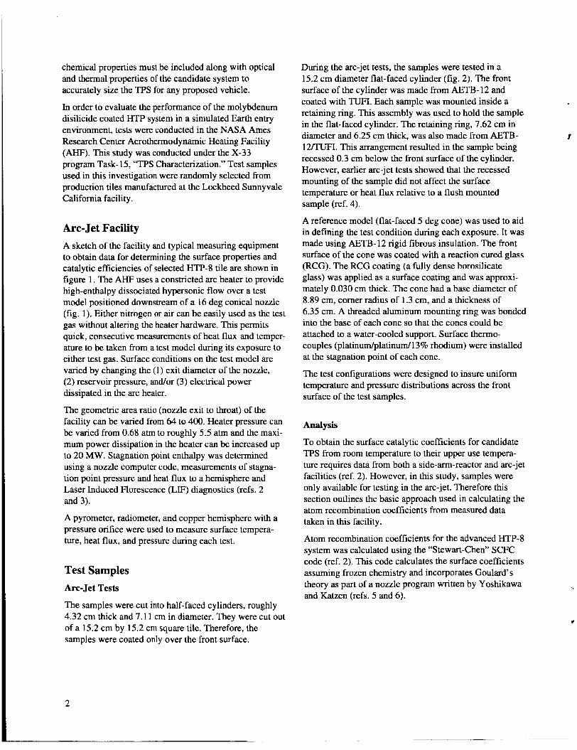
Arc- Jet Facility A sketch of the facility and typical measuring equipment to obtain data for determining the surface properties and catalytic efficiencies of selected HTP-8 tile are shown in figure 1. The AHF uses a constricted arc heater to provide high-enthalpy dissociated hypersonic flow over a test model positioned downstream of a 16 deg conical nozzle (fig. 1). Either nitrogen or air can be easily used as the test gas without altering the heater hardware. This permits quick, consecutive measurements of heat flux and temper- ature to be taken from a test model during its exposure to either test gas. Surface conditions on the test model are varied by changing the (1) exit diameter of the nozzle, (2) reservoir pressure, and/or (3) electrical power dissipated in the arc heater.
The geometric area ratio (nozzle exit to throat) of the facility can be varied from 64 to 400. Heater pressure can be varied from 0.68 atm to roughly 5.5 atm and the maxi- mum power dissipation in the heater can be increased up to 20 MW. Stagnation point enthalpy was determined using a nozzle computer code, measurements of stagna- tion point pressure and heat flux to a hemisphere and Laser Induced Florescence (LIF) diagnostics (refs. 2 and 3).
A pyrometer, radiometer, and copper hemisphere with a pressure orifice were used to measure surface tempera- ture, heat flux, and pressure during each test.
Test Samples Arc-Jet Tests
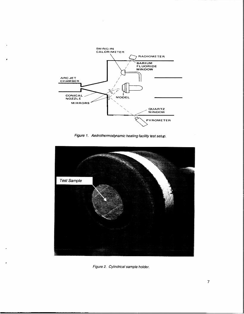
The samples were cut into half-faced cylinders, roughly 4.32 cm thick and 7.1 1 cm in diameter. They were cut out of a 15.2 cm by 15.2 cm square tile. Therefore, the samples were coated only over the front surface.
During the arc-jet tests, the samples were tested in a 15.2 cm diameter flat-faced cylinder (fig. 2). The front surface of the cylinder was made from AETB- 12 and coated with TUFI. Each sample was mounted inside a retaining ring. This assembly was used to hold the sample in the flat-faced cylinder. The retaining ring, 7.62 cm in diameter and 6.25 cm thick, was also made from AETB- 12/TUFI. This arrangement resulted in the sample being recessed 0.3 cm below the front surface of the cylinder. However, earlier arc-jet tests showed that the recessed mounting of the sample did not affect the surface temperature or heat flux relative to a flush mounted sample (ref. 4).
A reference model (flat-faced 5 deg cone) was used to aid in defining the test condition during each exposure. It was made using AETB-12 rigid fibrous insulation. The front surface of the cone was coated with a reaction cured glass (RCG). The RCG coating (a fully dense borosilicate glass) was applied as a surface coating and was approxi- mately 0.030 cm thick. The cone had a base diameter of 8.89 cm, comer radius of 1.3 cm, and a thickness of 6.35 cm. A threaded aluminum mounting ring was bonded into the base of each cone so that the cones could be attached to a water-cooled support. Surface thermo- couples (platinum/platinum/l3% rhodium) were installed at the stagnation point of each cone.
The test configurations were designed to insure uniform temperature and pressure distributions across the front surface of the test samples.
Y
Analysis
To obtain the surface catalytic coefficients for candidate TPS from room temperature to their upper use tempera- ture requires data from both a side-arm-reactor and arc-jet facilities (ref. 2). However, in this study, samples were only available for testing in the arc-jet. Therefore this section outlines the basic approach used in calculating the atom recombination coefficients from measured data taken in this facility.
Atom recombination coefficients for the advanced HTP-8 system was calculated using the “Stewart-Chen” SCFC code (ref. 2). This code calculates the surface coefficients assuming frozen chemistry and incorporates Goulard’ s theory as part of a nozzle program written by Yoshikawa and Katzen (refs. 5 and 6) .

Y
Goulard’s theory: qw = 0.66 Pr -213 (p2J12)112
x [(du, /ds)FFr12[Hm -Hw]
where
+i = (1 + 0.47 S,-213
To calculate the reaction rate constant from Goulard’s theory (ref. 5) requires inputs of gas properties from the free-stream, shock-layer and stagnation-point regions of the flow Gas pmpefles In t4e c d p ZT nhtized kern th.:: Aerotherm Chemical Equilibrium (ACE) code (ref. 7) and using Gupta’s thermodynamic properties (ref. 8).
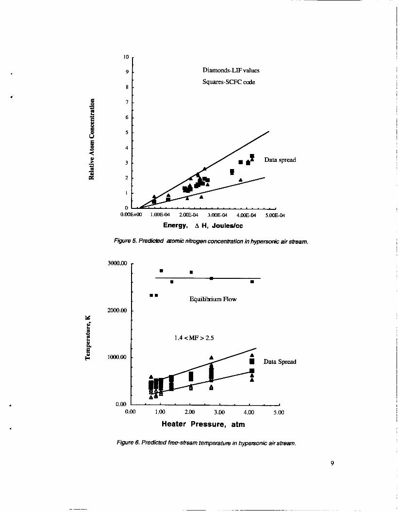
The thermodynamic state-of-the-gas in the free stream was defined in terms of the frozen Mach number. The frozen Mach number was determined using an iteration process between the total enthalpy and velocity or nitrogen mass fraction as obtained determined from LIF measurements and analytical techniques. The frozen Mach number during tests varied Erom 1.2 to 2.5. C a e - sponding free-stream velocity, relative nitrogen atom concentrations, and gas temperatures for these arc-jet tests are shown in figures 3 through 6. Based on the Knudsen number, properties behind the bow shock wave were calculated assuming a weak bow shock wave in front of the blunt models (ref. 2). In addition, Goulard’s solution requires the velocity gradient at the stagnation point of the model. The velocity gradient was derived from heat fluxes measured from both a hemisphere and a flat-faced cylinder in the arc-jet flow and the following basic relationship,
where (duJds),, = l/Rwd( P,, - P-)lpm.
Finally, using the two basic assumptions: (1) a first-order reaction occurs on the surface of the coating, and (2) the energy accommodation coefficient p for the material is unity. The following well-known expression can be used to calculate the atom recombination coefficients for the material.
where k, is the catalytic velocity determined from for the experiment.
Relative Coefficient for Air
The SCFC code also calculates a relative reaction rate constant kw for each material using only air test data. The equation, developed by Rosner (ref. 9), assumes a par- tially dissociated diatomic gas, frozen flow (gas phase recombination in the shock layer is neglected), and finally Tw << Teo SO that aiq(Tw, p) <<aie. With these assumptions he showed that the following semi-empirical relationship results:
Parameters qmin and qmm were obtained from Goulard‘s theory by setting I$ = 0 and Q = 1 .O, respectively. The stagnation point heat flux 90, used in eq. 4, is equal to the radiated heat flux plus the amount conducted into the model. The relative recombination coeffkient YA for the TPS is calculated again using eq. 3.
Experiments Arc Jet
During each test, the heat flux to an RCG coated model was measured along with the heat flux to the test model using a radiometer. Surface temperature data were obtained from both models using pyrometer measure- ments. During each test, stagnation point pressure and heat flux to a water-cooled copper 10.16 cm diameter hemisphere were measured, and free-stream properties were determined from data taken using Laser Induced Florescence &IF) measurement techniques (ref. 2). In addition to calculating atom recombination coefficients for each sample, surface characterization data were also obtained during this study. Photographs, spectral reflectance, and surface chemistry measurements were taken of each sample before and after arc-jet exposure. Photographs included scanning electron microphoto- graphs (SEMs) of the samples. Room temperature spectral reflectance measurements were made using a BIO-RAD model FTS 40 (wavelength range 0.25 microns to 2.5 microns) and a Perkin Elmer model 310 (wavelength range 2.5 microns to 18 micron) spectrophotometers. The surface analysis was performed using x-ray fluorescence elemental analysis.
3

Results and Discussion
A summary of the arc-jet test data taken during this investigation is given in table 1. The test number, enthalpy, surface temperature, heat flux, relative catalytic efficiency, total hemispherical emittance, and post test remarks are listed for both the air and nitrogen exposures. These data show that the enthalpy varied from 14.0 MJkg to 21.4 MJ/kg and the flux from 13.1 W/cm2 to 29.7 W/cm2. The catalytic efficiency of the molybdenum disilicide coated HTP-8 is higher than an RCG coated insulation, which is basically a borosilicate glass matrix, during exposures in both air and nitrogen. However, catalytic efficiency of the coating is heavily dependent on the test gas. The relative catalytic efficiency of the coating decreases during its exposure to air, but increases during exposure to nitrogen. On the other hand, the total hemispherical emittance remained at roughly 0.9 after exposure to both arc-jet flow environments. Finally, the coating cracked during the rapid cooldown after it reached temperatures above 1487 K in both arc-jet test environments.
Pre- and post-test photographs and Scanning Electron microphotographs (SEMs) of the HTP-8 test samples are shown in figures 7 and 8. The pre-test photograph was taken with the sample in the cylindrical holder (fig. 7a). The post-test photograph of the sample was taken outside the holder (fig. 7b). It shows insulation shrinkage (cavity) occurred at the side of the cylinder shaped sample just beneath the coating. This cavity was formed as a result of the surface cracks, formed after test two, increasing in size during test three in air (table 1) and allowing hot boundary gases to penetrate the insulation. The SEM data indicate that the coating on the pre-test sample was basically heterogeneous (evident by the surface charging shown in the photograph). This is could be a result of the coating being under-fiied during the manufacturing process (fig. 8a). Figure 8b indicates that the coating has been sintered after the arc-jet exposures, and surface cracks also occurred at the center of the sample. Figure 8c shows a fully dense coating with a thickness of roughly 0.050 cm. The coating did not penetrate into the fibrous insulation. The molybdenum disilicide coating cracked in a similar fashion after exposure to the nitrogen flow.
Surface chemistry data (ratio of oxygen to silicon) implies that silicon dioxide was formed on the surface as a result of the atomic oxygen present in the air flow (fig. 9). Also, these data show the loss of molybdenum disilicide from the surface of the coating during the exposures. Exposure of the sample to the dissociated nitrogen arc-jet flow resulted in little or no change in surface chemistry. However, there was a small effect on the optical
properties after exposure to the nitrogen environment
These changes are reflected by a slight decrease in the reflectance over the long wavelength region of the spectra (fig. loa). Total hemispherical emittance was calculated using the reflectance data and assuming that the surface of the samples was nontransparent (fig. lob). These values were compared with those calculated directly from the arc-jet measurements of surface temperature and heat flux. After arc-jet exposure in the nitrogen, the total hemispherical emittance is slightly higher than those values calculated after its exposure to air. The total hemispherical emittance values directly calculated from arc-jet data compared well with values calculated from the reflectance data. The total hemispherical emittance of the molybdenum disilicide coated HTP samples is close to 0.9 over the entire temperature.
(fig. 10).
i?
Atom Recombination Coefficients
Finally, the atom recombination coefficients for the molybdenum disilicide coated HTP-8 were calculated using the arc-jet data and the SCFC code (fig. 11). Arrhenius expressions fitted to the calculated coefficients for this coated system are given below.
Nitrogen:
(1264 K < Tw < 1589 K) yN = 675e - 1173OmW
Oxygen:
(1367 K e Tw < 1542 K)
yo = 2.5E - 1 0 e 29046mw
Air:
(1367 K < Tw e 1542 K)
(5)
yA = 7.OE-4e 8050mw (7)
The coefficients for this molybdenum disilicide coating system are characteristic of similar systems which form SiO, on their surface after arc-jet exposure in dissociated air (ref. 2). Examples are TUFI, which has a lower concentration of molybdenum disilicide on its surface, and silicon carbide. However, the LMMS molybdenum disilicide coating system has a higher catalytic efficiency for both oxygen and nitrogen atom recombination coefficients than either of these other two systems. Comparing the air coefficients over the same temperature range for TUFI and the LMMS coating shows that the LMMS system has a factor two higher catalytic efficiency
4

i
than TUFI (TUFI 0.14 c yA < 0.062, and the LMMS system 0.252 < yA c 0.129).
Conclusions Surface characterization of the LMMS molybdenum disilicide coated "IT-8 insulation was performed over surface temperatures ranging from roughly 1260 K to 1600 K in the NASA Ames Research Center Aerothermo- dymanic Heating Facility. Results from this study showed:
(1) Total hemispherical emittance of the MoSi, coating remained basically unchanged after exposure to dissociated arc-jet airflow.
(2) Surface chemistry data indicated the loss of MoSi, and the possible formation of a thin layer of SiO, over the surface of the coating during arc-jet exposure in air. During the nitrogen exposures, no reaction took place.
probably due to a large mismatch in the thermal expansion coefficient between coating and insulation.
(4) Insulation damage below the fully dense coating as a result of the cracks developed in the coating during arc-jet exposure.
(5 ) Catalytic efficiency of the LMMS coating is much higher, but has similar characteristics to TUFI and silicon carbide.
11) rnating ~ ~ 1 . s ~ c i ~ q ~ & esr &=-jet e ~ p x - ~ y \-/ ------
(6) In order to make accurate predictions of the heating over an SSTO using the LMMS molybdenum disilicide coating system, more extensive data from the side-ann reactor are needed to fully define its catalytic efficiency.
References 1. Office of Space Systems Development, NASA
Headquarters: Access to Space Study. Summary Report, January 1994. AIAA Journal, vol. 2, May 1965, pp. 945-948.
Stewart, D. A.: Surface Catalysis and Characteriza- tion of Proposed TPS for Access-to-Space Vehicles. NASA TM-112206, July 1997.
Stewart, D. A.; Chen, Y. K.; Barnford, D. J.; and Romanovsky, A. B.: Predicting Material Surface Catalytic Efficiency using Arc-Jet Tests. AIAA Paper 95-2013, June 1995.
Pincha, E. M. W.: Effect of Surface Catalysis on Heating to Ceramic Coated Thermal Protection Systems for Transahnospheric Vehicles. AIAA Paper 88-2706, June 1988.
2.
3.
4. Stewart, D. A.; Henline, W. D.; Kolodziej, P.; and
5. Goulard, R.: On Catalytic Recombination Rates in gy-$lxG~c s'Gg@&Gii xai Timlisfei- j,i
pp. 737-745. Propulsion, vol. 28, no. 11, November 1958,
Yoshikawa, K. K.; and Karzen, E. D.: Charts for Air-Flow Properties in Equilibrium and Frozen Flows in Hypervelocity Nozzles. NASA
Tong, H.: Non-equilibrium Chemistry Boundary Layer Integral Matrix Procedure. Acurex Corp., Mt. View, Calif., Aerotherm Dept., UM-73, April 1973.
Gupta, R N.; Thompson, R. A.; and Kam-Pui, L.: A Review of Reaction Rates and Thermodynamic and Transport Properties for an 11 Species Air Model for Chemical And Thermal Non equilibrium Calculations to 30,000 K. NASA
6.
TN D-693, 1961.
7.
8.
RP-2232, August 1990.
9. Rosner, D. E.: Analysis of Air Arc-Tunnel Data. AIAA Journal, vol. 2, May 1965, pp. 945-948.
5

Table 1. Summary of Arc-Jet Tests on LMMS Molybdenum Disilicide Coated HTP
9WJ9RCG Test HE0 Tw 9w BTUAbm "F BTUlft2-s
E, Post-test remarks
2000 15.6 1.53
2216 21 .o 1.38
2316 26.0 1.12
NITROGEN
0.9 No cracks
Coating showed thermal 0'87 stress cracks near edges
~~
Major insulation shrinkage 0'9 and increased crack sizes
1
2
3
V
7600
7800
8600
6
1.24
1.47
1.53
0.9 No cracks
0.9 No cracks
0.87 Edge cracks
SWING- IN CALORIMETER
ARC-JET CHAMBER
NOZZLE \
MIRRORS \ \
~
Figure 1. Aedrothermodynarnic heating facility test setLp.
Figure 2. Cylindrical sample holder.
7

Solid symbols, SCFC code
Open symbols, LIF diagnostics
6000
2000-
1OOO-
0 I I I I I
Figure 3. Correlation between predicted velocity in air from SCFC code and laser diagnostics.
8000-
7000-
6000-
e
2000 -1 1 1000
5 0 0 1 2 3 4
Heater Pressure, atm
Figure 4. Comparison between predicted velocities in nitrogen from SCFC code and laser diagnostics.
8
8 F
10
9 .
8 -
7 -
6 .
5 -
Diamonds-LIF values
Squares-SCFC code
-
spread
O.OOE+OO 1.00E-04 2.00E-04 3.00E-04 4.00E-04 5.00E-04
Energy, A H, Jouledcc
Figure 5. Predicled atomic nitrogen concenhtion in hyperso& air siream.
2000.00 t ..
Equilihium Flow
1.4 <MF > 2.5
Data Spread
0.00 I I
0.00 1 .OO 2.00 3 .00 4.00 5.00
Heater Pressure, atm
Figure 6. Predicted free-stream temperature in hypersonic air stream.
9

(a) Pre- test
(b) Post-test
Figure 7. Pre- and post-test photographs of HTP with LMMS molybdenum disilicide coating.
10

(a) Pre-test surface, Mag = 99SX.
(b) Post-test surface, Mag. = 150X.
(e) Post-test cross section view of HTP coated tile. Mag. = 75X.
Figure 8. Scanning electron micrqohotogrqhs of the L MMS molybdenum disilicide coated HTP-8.
11

6 0 0 0
5 0 0 0
4000
3000
2000
1000
0 0 1 2 3 4 5 6 7 9 1 0
(a) Pre test
.
6000
5 0 0 0
4000
3000
2000
1000
0
6000
5000
4000
3000
2000
1000
0 0 1 2 3 4 5 6 7 8 9 1 0
Energy, keV (c) Post nitrogen exposure
Figure 9. Effect of arc-jet exposure on the chemistry of LMMS molybdenum disilicide coated HTP.
12

aa 0 r 0
80
5 70
60
3
3 - a
& 50
40 c
=E aa 30 I
0.3 E
(A 0.2
0 + 0.1
i I
+.r
- 20
CI !! 0 1 0 aa u) = o
-
-
-
Pre &Post test air 7 A
Post test nitrogen 0 2 4 6 8 1 0 12 14 16 18
Wavelength, microns
Figure 10. Effect of arc-jet exposure on the optical properties of the cmting.
13

ci c
1
0.1
0.01
0.001
0.0001 0.0004 0.0008 0.001 2 0.001 6
(a) Nitrogen
1
0.1
0.01
0.001
0.0001 0.
1
0.1
0.01
0.001
0.0001
0004 0.0008 0.001 2 0.001 6
( 4 oxvsen
0.0004 0 . 0 0 0 8 0.0012 0.001 6
1 /Temperature, K-’ (c) Air
Figure 1 1. Atom tecombination coefficients for the advanced HTP coating system.
14

REPORT DOCUMENTATION PAGE
. TITLE AND SUBTITLE
Surface Characterization of LMMS Molybdenum Disilicide Coated HTP-8 Using Arc-Jet Hypersonic Flow
Form Approved OMB NO. 0704-0188
. AUTHOR(S)
David A. Stewart
14. SUBJECT TERMS
Effect of surface catalysis on surface heating to molybdenum disilicide coated ceramic, X-33 ceramic TPS for body flap and base region
17. SECURITY CLASSIFICATION 18. SECURITY CLASSIFICATION 19. SECURITY CLASSIFICATION OF REPORT OF THIS PAGE OF ABSTRACT
Unclassified Unclassified
. PERFORMING ORGANIZATION NAME(S) AND ADDRESS(ES)
15. NUMBER OF PAGES
19
A03 16. PRICE CODE
20. LIMITATION OF ABSTRAC
Ames Research Center Moffett Field, CA 94035- 1000
. SPONSORlNGlMONlTORlNG AGENCY NAME(S) AND ADDRESS(ES)
National Aeronautics and Space Administration Washington, DC 20546-0001
5. FUNDING NUMBERS
242-33-0 1
B. PERFORMING ORGANIZATION REPORT NUMBER
A-00V00 10
10. SPONSORlNGlMONlTORlNG AGENCY REPORT NUMBER
NASA/TM-2000-2095 88
1. SUPPLEMENTARY NOTES
Point of Contact: David A. Stewart, Ames Research Center, MS 234-1, Moffett Field, CA 94035-1000 (650) 604-6614
2a. DlSTRlBUTlONlAVAlLAElLlTY STATEMENT 12b. DISTRIBUTION CODE
Unclassified - Unlimited Subject Category 27 Distribution: Standard Availability: NASA CAS1 (301) 621-0390
I
3. ABSTRACT (Maximum 200 words)
Surface properties for an advanced LockheedMartin Missile and Space (LMMS) molybdenum disilicide coated insulation (HTP-8) were determined using arc-jet flow to simulate Earth entry at hypersonic speeds. The catalytic efficiency (atom recombination coefficients) for this advanced thermal protection system was determined from arc-jet data taken in both oxygen and nitrogen streams at temperatures ranging from 1255 K to roughly 1600 K. In addition, optical and chemical stability data were obtained from these test samples.