little joe ii test launch vehicle nasa project apollo. volume 1 management
TRANSCRIPT
8/6/2019 Little Joe II Test Launch Vehicle NASA Project Apollo. Volume 1 Management
http://slidepdf.com/reader/full/little-joe-ii-test-launch-vehicle-nasa-project-apollo-volume-1-management 1/157
8/6/2019 Little Joe II Test Launch Vehicle NASA Project Apollo. Volume 1 Management
http://slidepdf.com/reader/full/little-joe-ii-test-launch-vehicle-nasa-project-apollo-volume-1-management 2/157
GDC-66-042
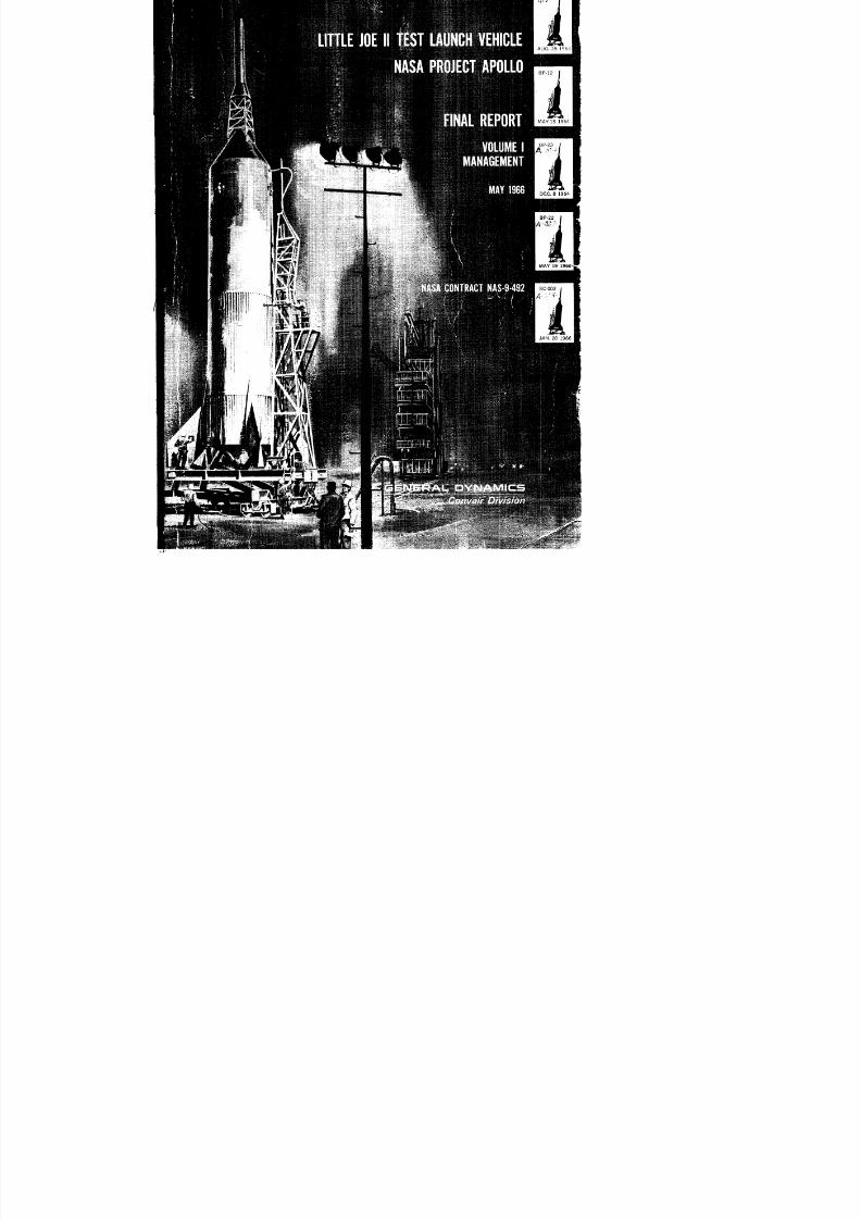
LITTLEOEI TESTLAUNCHEHICLENASAROJECTPOLLO
FINALEPORT
VOLUMEMANAGEMENT
MAY1966
NASACONTRACTAS-9-492
t
Prepared By
CONVAIR DMSION OF GENERAL DYNAMICS
For
National Aeronautics and Space Administration
Manned Spacecraft Center
Houston, Texas
8/6/2019 Little Joe II Test Launch Vehicle NASA Project Apollo. Volume 1 Management
http://slidepdf.com/reader/full/little-joe-ii-test-launch-vehicle-nasa-project-apollo-volume-1-management 3/157
FOREWORD
The Little Joe II Program, a part of theApollo Spacecraft Program
and identified by National Aeronautics and Space Administration,
Manned Spacecraft Center as Contract NAS 9-492, was awarded to
the Convair Division of General Dynamics Corporation on 17 May
1962. The program was, in essence, completed with the launch of
the last scheduled vehicle on 20 January 1966.
The purpose of this report is to describe the vehicles evolved, the
results of the tests and the principles employed to accomplish the
program requirements. The report is issued in two volumes to
simplify the presentation of the material. Volume I contains the
managerial and other nontechnical aspects of the program; Volume
II contains the design, technical and launch operations portions.
Milton A. Silveira,
Program Manager L. J. II, ram Manager L. J. II,
NASA - MSC Convair Division of
General Dynamics
8/6/2019 Little Joe II Test Launch Vehicle NASA Project Apollo. Volume 1 Management
http://slidepdf.com/reader/full/little-joe-ii-test-launch-vehicle-nasa-project-apollo-volume-1-management 4/157
INTRODUCTION
The purpose of the Little Joe II Program was to man-rate the
launch escape system designed by the Space and Information Sys-
tems Division of North American Aviation, Inc., for the Apollo
Command Module. This objective was to be accomplished on a tight
schedule and at a minimum cost. The program was initiated as a
result of an intensive survey by NASA of the inventory of launch ve-hicles; it was discovered that no vehicle existed which had the pay-
load capability and thrust versatility to meet mission profiles at a
reasonable cost.
The Little Joe II vehicle was designed for an 80,000 pound pay-
load capability. Thrust was provided by off-the-shelf Algol solid-
p r op e 11 an t motors, manufactured by the Aerojet-General Corp.
Versatility of performance was achieved by using only the number
of primary motors (up to seven) required to perform the mission.
Additional vehicle versatility was achieved by use of two ver-
sions of vehicle fins. Fixed fins were used for ballistic trajecto-
ries. Thiokol Corporation's Recruit rocket motors were used as
booster motors, to supplement lift-off thrust.
This report documents, for historic'a/benefit, the philosophies
employed, changes found necessary, results obtained and lessons
learned during the Little Joe II Program. Hopefully this informa-
tion will prove useful to future programs.
A bibliography lists publications pertinent to the contents of
Volume I. In addition, specific supporting material is referenced
in the text.
iii
8/6/2019 Little Joe II Test Launch Vehicle NASA Project Apollo. Volume 1 Management
http://slidepdf.com/reader/full/little-joe-ii-test-launch-vehicle-nasa-project-apollo-volume-1-management 5/157
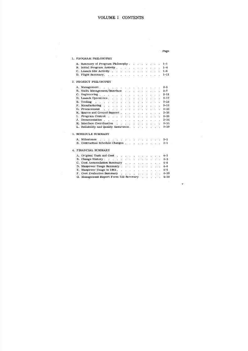
VOLUME I CONTENTS
Page
i. PROGRAM PHILOSOPHY
A. Summary of Program Philosophy ........ 1-1
B. Initial Program Activity ........... 1-4
C. Launch Site Activity ............ 1-6
D. Flight Summary .............. 1-11
2. PROJECT PHILOSOPHY
A. Management ......... ...... 2-1
B. NASA Management/Interface ......... 2-7
C. Engineering ............... 2-11
D. Launch Operations ............. 2-17
E. Tooling ................ 2-18
F. Manufacturing .............. 2-19
G. Procurement .............. 2-23
H. Spares and Ground Support .......... 2-26
I. Program Control ............. 2-28
J. Documentation .............. 2-34
K. Interface Coordination ........... 2-35
L. Reliability and Quality Assurance ........ 2-39
3. SCHEDULE SUMMARY
A. Milestones ............... 3-1
B. Contractual Schedule Changes ......... 3-1
4. FINANCIAL SUMMARY
A. Original Task and Cost ........... 4-1
B. Change History .............. 4-2
C. Cost Accumulation Summary ......... 4-6
D. Manpower Usage Summary .......... 4-6
E. Manpower Usage in 1964 ........... 4-6
F. Cost Evaluation Summary .......... 4-10
G. Management Report Form 533 Summary ..... 4-10
v
8/6/2019 Little Joe II Test Launch Vehicle NASA Project Apollo. Volume 1 Management
http://slidepdf.com/reader/full/little-joe-ii-test-launch-vehicle-nasa-project-apollo-volume-1-management 6/157
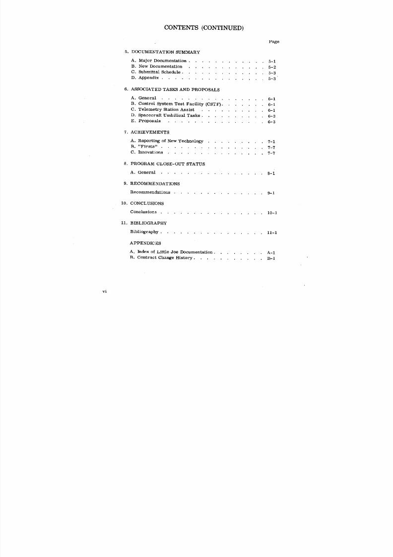
CONTENTS (CONTINUED)
Page
5. DOCUMENTATION SUMMARY
A. Major Documentation ............ 5-1
B. New Documentation ............ 5-2
C. Submittal Schedule ............. 5-3
D. Appendix ................ 5-3
6. ASSOCIATED TASKS AND PROPOSALS
A. General ................ 6-1
B. Control System Test Facility (CSTF) ....... 6-1
C. Telemetry Station Assist .......... 6-1
D. Spacecraft Umbilical Tasks .......... 6-3
E. Proposals ............... 6-3
7. ACHIEVEMENTS
A. Reporting of New Technology ......... 7-1
B. "Firsts" ................ 7-7
C. Innovations ............... 7-7
8. PROGRAM CLOSE-OUT STATUS
A. General ................ 8-1
9. RECOMMENDATIONS
Recommendations .............. 9-1
10. CONCLUSIONS
Conclusions ................ 10-1
11. BIBLIOGRAPHY
Bibliography ................ 11-1
APPENDICES
A. Index of LittleJoe Documentation ........ A-I
B. Contract Change History........... B-I
vi

8/6/2019 Little Joe II Test Launch Vehicle NASA Project Apollo. Volume 1 Management
http://slidepdf.com/reader/full/little-joe-ii-test-launch-vehicle-nasa-project-apollo-volume-1-management 7/157
VOLUME I ILLUSTRATIONS
Figure Title Page
1-1 Little Joe II- As Originally Planned Vs. Final Configuration .... 1-3
1-2 Launch Complex Pad Area .................. 1-4
1-3 General Area of Convair Activities for LJ-II/Apollo Program
at WSMR ..................... 1- 5
1-4 Vehicle Schedule Summary ............... 1-7
1-5 Historical Summary of LJ-II/Apollo Missions Flown at WSMR, LC-36 . 1-8
1-6 Pre-Launch Through Thrust Termination/Spacecraft Abort Sequence -
BP-12 Mission A-001 ................. 1-9
1-7 Launch Vehicle 12-51-3 With SC-002 at Liftoff ......... 1-10
1-8 LJ-II/Apollo Abort Test Regions ............. 1-12
1-9 WSMR Apollo Flight Program Mission Objectives ........ 1-13
1-10 Launch Vehicle Configuration Summary ........... 1-15
1-11 Launch Data Digest .................. 1-16
2-1 Original Organization Chart - Little Joe H Program ....... 2-2
2-2 Final Organization Chart - Little Joe II Program ........ 2-3
2-3 Key Departmental Contacts ............... 2-4
2-4 President Staff Meeting ................ 2-6
2-5 Little Joe H Engineering Area .............. 2-6
2-6 Project Identification Badge ............... 2-7
2-7 Open House After Completion of First Vehicle ......... 2-8
2-8 NASA Organizational History ............... 2-10
2-9 NASA/Convair Design Review ............... 2-10
2-10 Design Engineering Scope (Typical) - Little Joe H ........ 2-12
2-11 Equipment Installation Layout (Vehicle Station 34.75) ....... 2-15
2-12 Bulkhead 34.75 Assembly Fixture ............. 2-19
vii
8/6/2019 Little Joe II Test Launch Vehicle NASA Project Apollo. Volume 1 Management
http://slidepdf.com/reader/full/little-joe-ii-test-launch-vehicle-nasa-project-apollo-volume-1-management 8/157
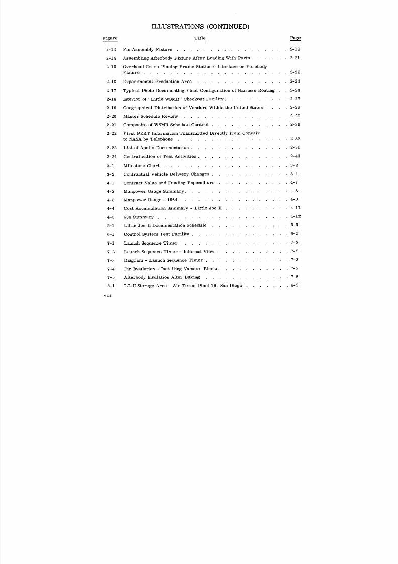
ILLUSTRATIONS (CONTINUED)
Figure Title Page
2-13 Fin Assembly Fixture ................. 2-19
2-14 Assembling Afterbody Fixture After Loading With Parts ...... 2-21
2-15 Overhead Crane Placing Frame Station 0 Interface on Forebody
Fixture ...................... 2-22
2-16 Experimental Production Area .............. 2-24
2-17 Typical Photo Documenting Final Configuration of Harness Routing . . 2-24
2-18 Interior of "Little WSMR" Checkout Facility .......... 2-25
2-19 Geographical Distribution of Vendors Within the United States .... 2-27
2- 20 Master Schedule Review ................ 2- 29
2-21 Composite of WSMR Schedule Control ............ 2-31
2-22 First PERT Information Transmitted Directly from Convair
to NASA by Telephone ................. 2-33
2-23 List of Apollo Documentation ............... 2-36
2-24 Centralization of Test Activities .............. 2-41
3-i Milestone Chart ................... 3-2
3-2 Contractual Vehicle Delivery Changes ............ 3-4
4-1 Contract Value and Funding Expenditure ........... 4-7
4-2 Manpower Usage Summary ................ 4-8
4-3 Manpower Usage - 1964 ................. 4-9
4-4 Cost Accumulation Summary - Little Joe II .......... 4-11
4-5 533 summary ................... 4-12
5-i Little Joe II Documentation Schedule ............ 5-5
6-I Control System Test Facility ............... 6-2
7-i Launch Sequence Timer ................. 7-2
7-2 Launch Sequence Timer - Internal View ........... 7-2
7-3 Diagram - Launch Sequence Timer ............. 7-3
7-4 Fin Insulation - Installing Vacuum Blanket .......... 7-5
7-5 Afterbody Insulation After Baking ............. 7-6
8-1 LJ-II Storage Area - Air Force Plant 19, San Diego ....... 8-2
oo°VII1

8/6/2019 Little Joe II Test Launch Vehicle NASA Project Apollo. Volume 1 Management
http://slidepdf.com/reader/full/little-joe-ii-test-launch-vehicle-nasa-project-apollo-volume-1-management 9/157
1 PROGRAM PHILOSOPHY SUMMARY
8/6/2019 Little Joe II Test Launch Vehicle NASA Project Apollo. Volume 1 Management
http://slidepdf.com/reader/full/little-joe-ii-test-launch-vehicle-nasa-project-apollo-volume-1-management 10/157
1 [ PROGRAM PHILOSOPHY SUMMARY
A. SUMMARY OF PROGRAM PHILOSOPHY
As a prerequisite to manned flightof an Apollo spacecraft, itwas necessary to
demonstrate the abilityofthe spacecraft's escape system during the launch-boost
phase of flight;hence the LittleJoe IIprogram was an important milestone in the over-
allApollo Project. The LittleJoe ITprogram was scheduled to accomplish early and
economical testing that would qualifythe Apollo Launch Escape System for use on
manned orbital or lunar missions. The original schedule required that the firstlaunch
be accomplished one year from date of go-ahead.
A modified project organization was used to manage this program. Under this
concept, selected senior key supervisors and staffmembers reported functionallyto
the program managers and administratively to their home group or department. This
type of organization afforded close control and coordination within the project as well
as with NASA.
Simplicity was the keynote of the LittleJoe IIdesign philosophy; this concept was
carried through the tooling and manufacturing phases of the program as well. The use
of corrugated aluminum skin is an example of the result of this approach; this type of
construction provided integral stiffenersand eliminated the need for stringers. Al-
though this design represented a minor weight penalty when compared to the more
costly aluminum sheet-stringer construction, itgreatly reduced design and construction
time. In addition, itreduced the overall number of parts in the vehicle.
Weight was not a limiting factor in the design of the vehicles, as most versions
required several thousand pounds of ballast to satisfythe mission trajectory require-
ments. The fact thatweight was not the limiting factor permitted conservatism of
design; e.g., over-designing primary structural members. As a result many struc-
tural proof tests were not required. Many other tests were accomplished in a con-
servative and simple fashion; e.g., tests of the thermal protection material were
accomplished under sea-level conditions in lieu of a vacuum environment. The sea-
level test was much more severe as the material was subjected to the rocket temper-
atures as well as to high dynamic pressure. Wherever possible, vehicle systems
were designed for use of readily available off-the-shelf components which had been
proven by use on other programs. As a result, qualification testing was kept to a
minimum. The foregoing philosophy significantly reduced program costs.
1-1
8/6/2019 Little Joe II Test Launch Vehicle NASA Project Apollo. Volume 1 Management
http://slidepdf.com/reader/full/little-joe-ii-test-launch-vehicle-nasa-project-apollo-volume-1-management 11/157
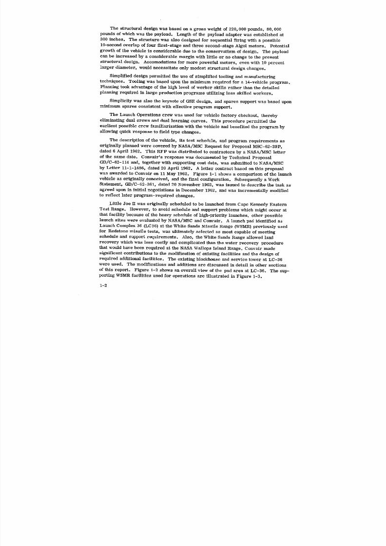
The structural design was based on a gross weight of 220,000 pounds, 80, 000
pounds of which was the payload. Length of the payload adapter was established at
300 inches. The structure was also designed for sequential firing with a possible
10-second overlap of four first-stage and three second-stage Algol motors. Potential
growth of the vehicle is considerable due to the conservatism of design. The payload
can be increased by a considerable margin with little or no change to the presentstructural design. Accomodations for more powerful motors, even with 10 percent
larger diameter, would necessitate only modest structural design changes.
Simplified design permitted the use of simplified tooling and manufacturing
techniques. Tooling was based upon the minimum required for a 14-vehicle program.
Planning took advantage of the high level of worker skills rather than the detailed
planning required in large production programs utilizing less skilled workers.
Simplicity was also the keynote of GSE design, and spares support was based upon
minimum spares consistent with effective program support.
The Launch Operations crew was used for vehicle factory checkout, therebyeliminating dual crews and dual learning curves. This procedure permitted the
earliest possible crew familiarization with the vehicle and benefited the program by
allowing quick response to field type changes.
The description of the vehicle, its test schedule, and program requirements as
originally planned were covered by NASA/MSC Request for Proposal MSC-62-39P,
dated 6 April 1962. This RFP was distributed to contractors by a NASA/MSC letter
of the same date. Convair's response was documented by Technical Proposal
GD/C-62-114 and, together with supporting cost data, was submitted to NASA/MSC
by Letter 11-1-1486, dated 20 April 1962. A letter contract based on this proposal
was awarded to Convair on 11 May 1962. Figure 1-1 shows a comparison of the launchvehicle as originally conceived, and the final configuration. Subsequently a Work
Statement, GD/C-62-361, dated 20 November 1962, was issued to describe the task as
agreed upon in initial negotiations in December 1962, and was incrementally modified
to reflect later program-required changes.
Little Joe H was originally scheduled to be launched from Cape Kennedy Eastern
Test Range. However, to avoid schedule and support problems which might occur at
that facility because of the heavy schedule of high-priority launches, other possible
launch sites were evaluated by NASA/MSC and Convair. A launch pad identified as
Launch Complex 36 (LC36) at the White Sands Missile Range (WSMR) previously used
for Redstone missile tests, was ultimately selected as most capable of meetingschedule and support requirements. Also, the White Sands Range allowed land
recovery which was less costly and complicated than the water recovery procedure
that would have been required at the NASA Wallops Island Range. Convair made
significant contributions to the modification of existing facilities and the design of
required additional facilities. The existing blockhouse and service tower at LC-36
were used. The modifications and additions are discussed in detail in other sections
of this report. Figure 1-2 shows an overall view of the pad area at LC-36. The sup-
porting WSMR facilities used for operations are illustrated in Figure 1-3.
1-2
8/6/2019 Little Joe II Test Launch Vehicle NASA Project Apollo. Volume 1 Management
http://slidepdf.com/reader/full/little-joe-ii-test-launch-vehicle-nasa-project-apollo-volume-1-management 12/157

8/6/2019 Little Joe II Test Launch Vehicle NASA Project Apollo. Volume 1 Management
http://slidepdf.com/reader/full/little-joe-ii-test-launch-vehicle-nasa-project-apollo-volume-1-management 13/157

8/6/2019 Little Joe II Test Launch Vehicle NASA Project Apollo. Volume 1 Management
http://slidepdf.com/reader/full/little-joe-ii-test-launch-vehicle-nasa-project-apollo-volume-1-management 14/157
NORTHNOMINALLAUNCHDIRECTION
LITTLE JOEII /PAYLOAD SERVtCETOWER(GANTRY)BLDG.NO. S- 2_355ONLAUNCHER
CABLESUPPORTMAST(FORCABLES TOTRENCH,
PYROREADY STORAGE MAGAZINESTO LAS CRUCES POWER ROOM & BH) FORTO ALMOGORDO _
_._ _ CONVAIR OPERATIONS
-- SUPPORTOFFICEINPORTABLESHED
R. T A ILE O. CONVAIRLAUNCH
12MILES CONVAIR( OPERATIONS TRAILER NO. O
IWSMR POSTAREA I J INSPECTIONTRAILERNO. ii _, POWER ROOM IN
BARRICADEDNASA BLDGS T-118& T-108 WSMR STRUCTURE
SECURITY BLDG. S'23356
WSMR HEADQUARTERS BLDG 100 • BLDGT-S26,,.v_. GUARDPOST 10'x12' BLOCKHOUSE BLDG.
FLAMMABLE FINTESTPAD NO. S-23350
CONVAIRMAIN OFFICE ENCLOSED STORAGE SHED ILC.36 CONTROL SYSTEMS 1,200 FT.FROM
& SHOPAREA TECHNICAL I TEST FACILIW LAUNCH PAD(BLDG1540) AREA ROCKET MOTOR LAUNCH COMPLEX 31 (CSTF)BUILDUPBLDGS VEHICLEASSEMBLY
21560 & 21564 BUILDINGNO. 'x 12_STORAGE SHEDNASA TELEMETRY
TRAILERSNO.1&
LITTLE JOEI I RECEIVING i2INSPECTION,ACS FIN ASSY- CONVAIRRN TEST OPERATIONS
BLDG 1520WSMR GUARD POSTtr_STR.& / 5' FLAMMABLESTORAGESHED
J ALGOLMOTORPREPARATION
/
BU]LDING1676 (FORPITCH-UPCOM'D] 3ROWAVE &MISC. STORAGE,ETC, NO. 11WSMRGUIDANCE& MAB26 H202 STORAGE DATA FROM
BLDG.1512CONTROL LAB ALGOL SHAPE- BLDG. 23.501 9.5 MILES COMPUTERS(FORCALIBR.) CHARGE STORAGE MILES
NAB 27
ALGOL MOTOR
WSMR
SECURITYGUARD POST
TO EL PASO CINDERBLOCKHUTSIS) _ C' STATION FORFPS-16 RADARTRACKINGAND FRW_2 TRANSMISSION(SQUIBS,IGNITERS,ETC. FOR COMMAND CONTROL/DESTRUCT SIGNALS.
ALSO MFSO STATIONFOR FLIGHTRANGESAFETY CONTROLVIACOMMAND
TO TERMINATELJ-IILGOL MOTOR THRUST (IFREQUIRED).
WSMRAIRPORTCONDRON FIELD
C-6062-3
I
¢_ Figure 1-3. General Area of Convair Activities for Little Joe II/Apollo Program at WSMR
8/6/2019 Little Joe II Test Launch Vehicle NASA Project Apollo. Volume 1 Management
http://slidepdf.com/reader/full/little-joe-ii-test-launch-vehicle-nasa-project-apollo-volume-1-management 15/157
to WSMR on 25 April 1963. Preliminary systems checkout of the vehicle was com-
pleted in San Diego on 3 May 1963. A Development Engineering Inspection (DEI) was
conducted 9 May 1963 and a number of requested changes were incorporated. Phase 1I
of the DEI was held 10 June 1963. A final systems checkout was initiated immediately
after this and completed 13 July 1963. The vehicle was then disassembled and delivered
to WSMR on 16 July 1963.
Engineering design for the attitude control vehicles was initiated on 23 July 1962.
The additional structural design required was completed in December 1962 and all
systems design was completed in August 1964. Fabrication of detail parts for the first
vehicle was started on 30 April 1963o Sub-assembly for the fins and elevons was
initiated on 25 July 1963. Major assembly of the forebody was completed on 11 October
and the afterbody on 18 October 1963, and these major assemblies were placed in
temporary storage. The forebody was removed from storage and final assembly
started on 2 December 1963. The afterbody was removed from storage on 12 November
and placed on Launcher 12-60-2 for fin flutter tests which were completed on 19 Decem-
ber 1963. Final assembly of the forebody was initiated on 2 December 1963 and the
unit was mated to the afterbody on 4 May 1964.
Preliminary OCI checkout was initiated on 5 May 1964 and was completed on 20
June 1964. Required changes such as instrumentation, pitch programmer, etc., were
incorporated. The final OCI checkout was initiated on 11 August and the Development
Engineering Inspection (DEI) was held on 20 August° DEI cleanup and OCI checkout
were completed on 12 September 1964. The vehicle was disassembled and shipped to
WSMR on 15 September 1964.
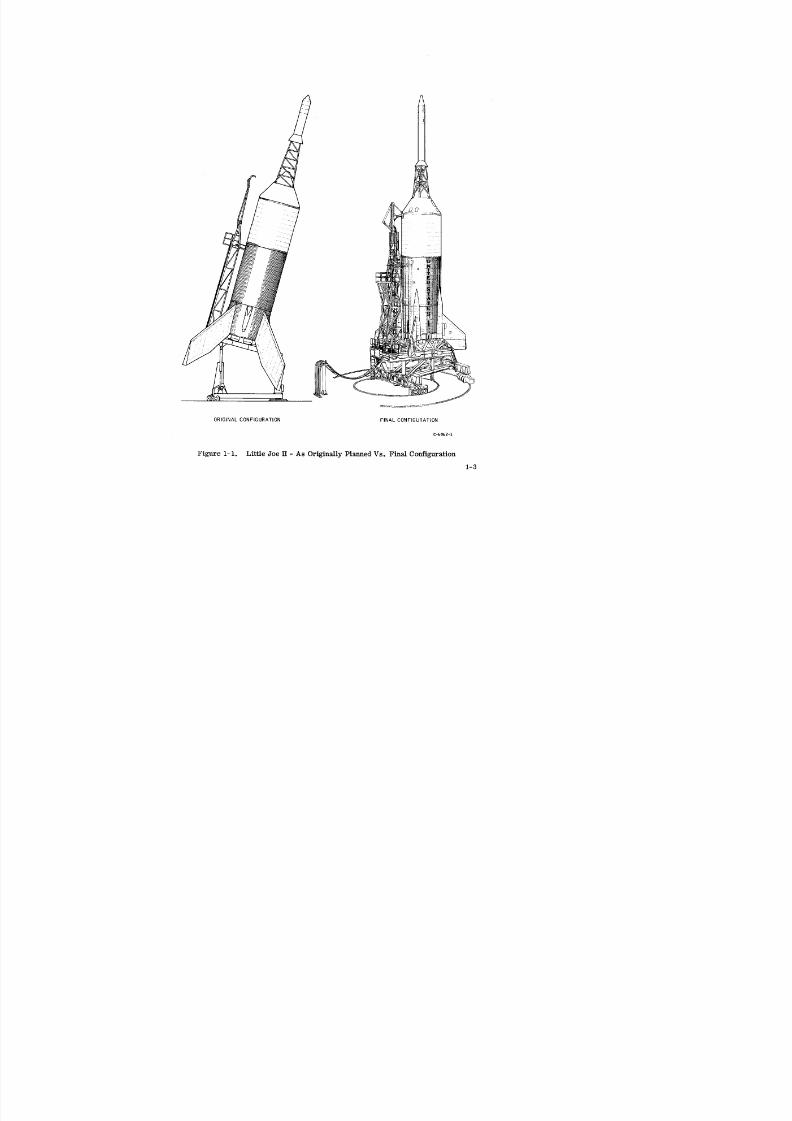
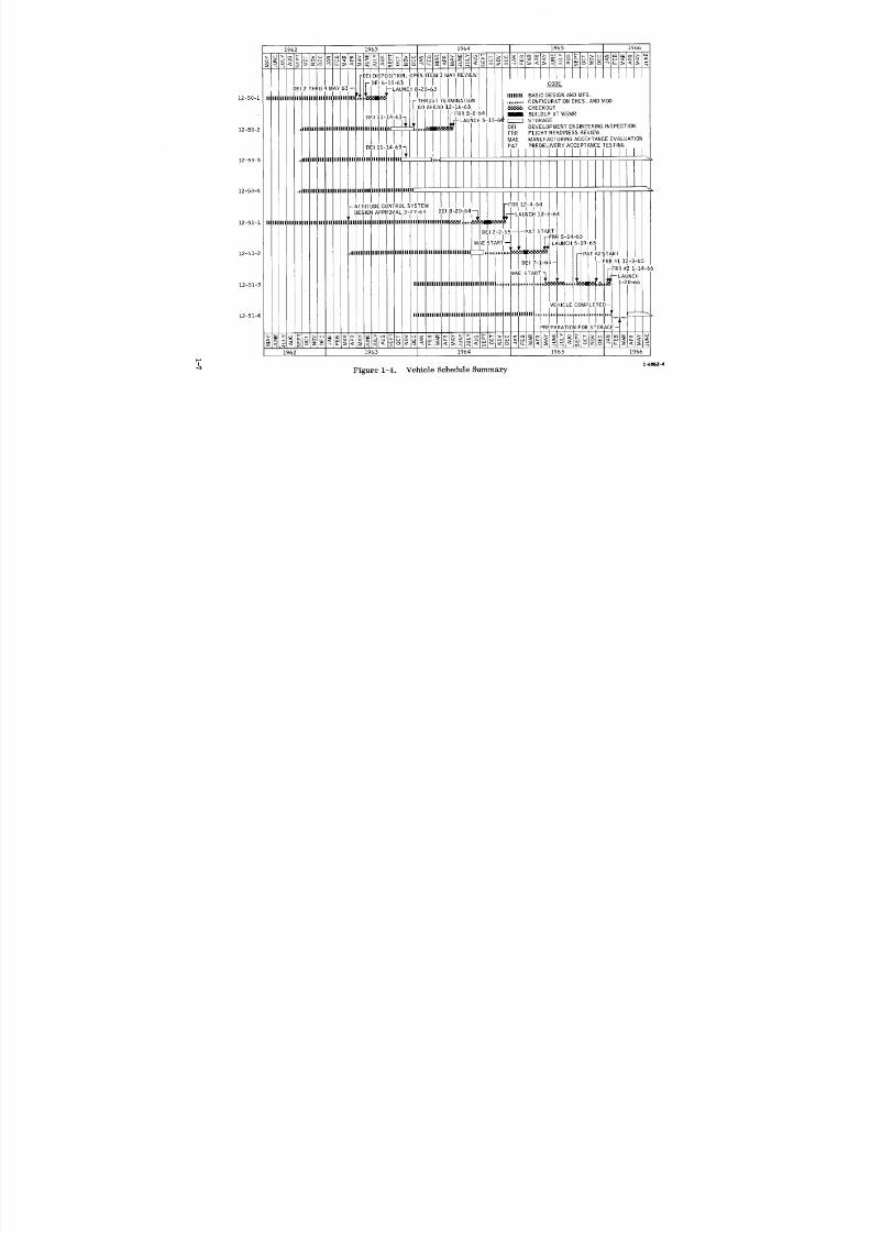
A summary of the typical life-span for this and the subsequent vehicles is illus-
trated in Figure 1-4. This summary identifies the following phases: 1) basic design
and manufacturing, 2) configuration changes and modifications, 3) checkout (on and offsite), 4) buildup off site, and 5) launch and/or storage.
C. LAUNCH SITE ACTIVITY
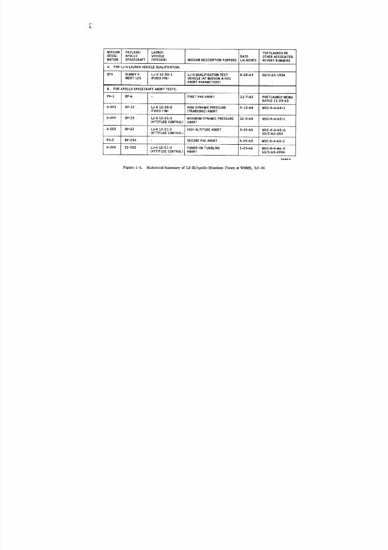
Five unmanned flight missions were accomplished during the program. The first
was a fixed-fin Qualification Test Vehicle (QTV) launched on 28 August 1963. This
was followed by a series of four launchings employing boilerplate or prototype Apollo
spacecraft which were capable of in-flight abort tests. Of these, one had fixed fins
and three were controllable vehicles. Two pad-abort tests were also accomplished by
NAA S&ID and NASA/MSC during the span-time of these tests, as noted in Figure 1-5.
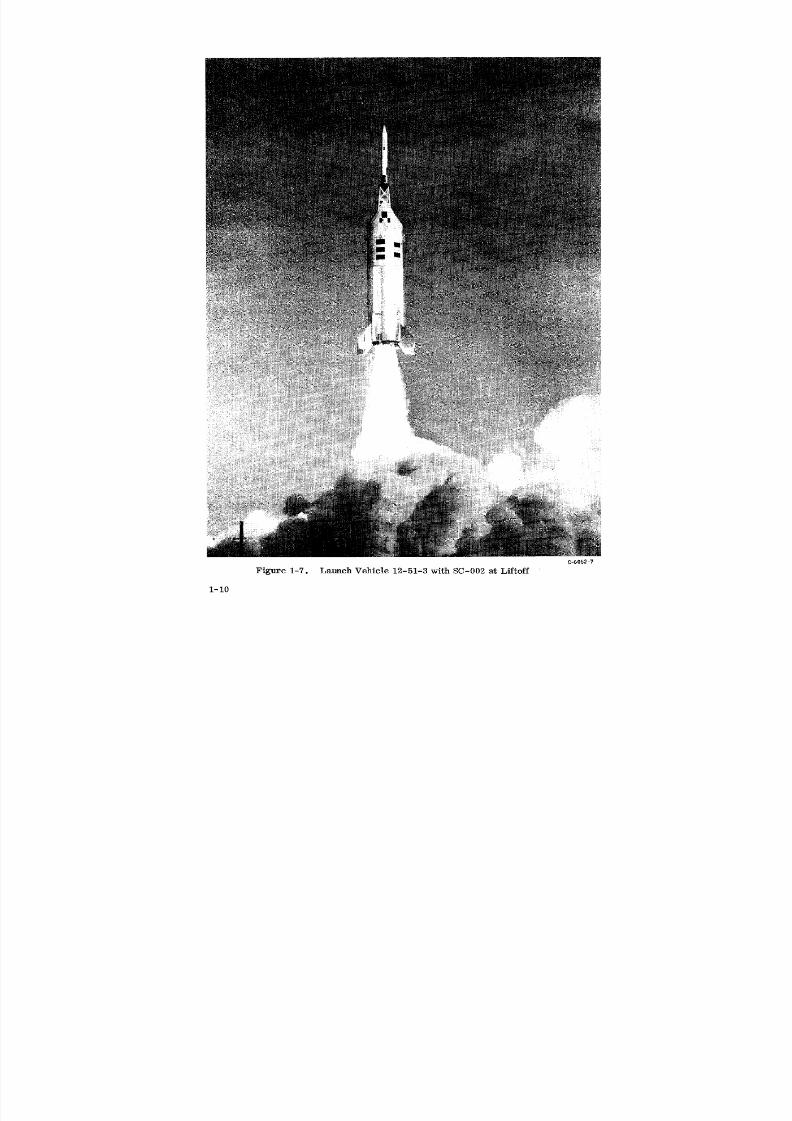
The sequence of launch events in Figure 1-6 shows part of the first LJ-II/BP-12 abortmission. The IM-H/SC-002 mission, accomplished on 20 January 1966, completed
the flight qualification of the Apollo spacecraft launch escape vehicle (LEV). Figure
1-7 shows the vehicle shortly after liftoff.
1-6
8/6/2019 Little Joe II Test Launch Vehicle NASA Project Apollo. Volume 1 Management
http://slidepdf.com/reader/full/little-joe-ii-test-launch-vehicle-nasa-project-apollo-volume-1-management 16/157
1962 1963 __ --____ _DEI DISPOSITION, OPENITEM 3 MAY REVIEW
'''-'allll CODEI _NCH 8-28-63
12-50-1 J ] I IIIIIIII BASIC DESIGN AND MFG.-THRUST TERMINATION ,,,,,,,,, CONFIGURATION CHGS. ANDMOD
GO AHEAD 12-16-63 _ CHECKOUT
-FRR518-64 / BUILDUP ATWSMRDEI 11-14-63 ....
t _ -LAUNCH 5-13-6_-_ STORAGE
! I DEI DEVELOPMENT ENGINEERINGINSPECTION12-50-2 Ill III)111 I FRR FLIGHT READINESS REVIEW
MAE MANUFACTURING ACCEPTANCE EVALUATIONDEI 11-14-63" PAT PREDELIVERY ACCEPTANCE TESTING
12-50-3 IIIIIIIIII I II III _ _--
12-50-4 Unlll III IIII III
- ATTITUDE CONTROL SYSTEM ,_FRR 12-4-64
DESIGN APPROVAL 5-27-63 DEI 8-20-64-- I I I l,,_-LAUNCH 12-8-64
,lllllllllllll Ill I ] I I12-51-1
DE! iTART
I I I I I -FReS-14-65 IMAE -LAUNCH 5-19-65
I I12-51-2 III1 III IIII IF .PAT #2 START
I i i LDEI
I r-- FRR #i 12-3-65
I ' I I I-'FRI_#_1'-14-66
MAE i ; I,I,II'AUN(_H
12-51-5 ] IIIIIiIIU'"' ,'1, _H_ _5,1,, 1-20-66
IIIVEHICLE COMPLETED--
PREPARATION FOR STORAGE-- i
1962 1963 1964 1965 _ 1966
p_I C-606Z-4
"_ Figure 1-4. Vehicle Schedule Summary
8/6/2019 Little Joe II Test Launch Vehicle NASA Project Apollo. Volume 1 Management
http://slidepdf.com/reader/full/little-joe-ii-test-launch-vehicle-nasa-project-apollo-volume-1-management 17/157
IO0
MISSION PAYLOAD/ LAUNCH POSTLAUNCHORDESIG- APOLLO VEHICLE DATE OTHERASSOCIATEDNATION SPACECRAFT (VERSION) MISSIONDESCRIPTIONPURPOSE LAUNCHED REPORTNUMBERS
A. FORLJ-II LAUNCHVEHICLEQUALIFICATION:
QTV DUMMY+ LJ-II 12-50-1 LJ-II QUALIFICATIONTEST 8-28-6.3 GD/C-63-193AINERT LES (FIXED FIN) VEHICLE (AT MISSIONA-O01
ABORTPARAMETERS)
B. FORAPOLLOSPACECRAFTABORTTESTS:
PA-1 BP-6 - FIRST PADABORT 11-7--6.3 POSTLAUNCHMEMODATED11-23-63
A-O01 BP-12 LJ-II 12-50-2 HIGHDYNAMICPRESSURE 5-13-64 MSC-R-A-64-1(FIXED FIN) (TRANSONIC)ABORT
A-O02 BP-23 LJ-II 12-51-1 MAXIMUMDYNAMICPRESSURE 12-8-64 MSC-R-A-65-1(ATTITUDECONTROL) ABORT
A-O03 BP-22 LJ-II 12-51-2 HIGHALTITUDE ABORT 5-19-65 MSC-R-A-65-2;(ATTITUDECONTROL) GD/C-65-143
PA-2 BP-23A - SECONDPADABORT 6-29-65 MSC-R-A-65-3
A-O04 SC-002 LJ-II 12-51-3 POWER-ONTUMBLING 1-20-66 MSC-R-A-66-3(ATTITUDE CONTROL) ABORT GD/C--65-190A
C"6062-5
Figure 1-5. Historical Summary of LJ-II/Apollo Missions Flown at WSMR, LC-36

8/6/2019 Little Joe II Test Launch Vehicle NASA Project Apollo. Volume 1 Management
http://slidepdf.com/reader/full/little-joe-ii-test-launch-vehicle-nasa-project-apollo-volume-1-management 18/157
(:;..6002-6I
Figure 1-6. Pre-Launch Through Thrust Termination/Spacecraft Abort Sequence - BP-12 Mission A-00I
8/6/2019 Little Joe II Test Launch Vehicle NASA Project Apollo. Volume 1 Management
http://slidepdf.com/reader/full/little-joe-ii-test-launch-vehicle-nasa-project-apollo-volume-1-management 19/157
C-6062 -7
Figure 1-7. Launch Vehicle 12-51-3 with SC-002 at Liftoff
1-10
8/6/2019 Little Joe II Test Launch Vehicle NASA Project Apollo. Volume 1 Management
http://slidepdf.com/reader/full/little-joe-ii-test-launch-vehicle-nasa-project-apollo-volume-1-management 20/157
Each of the LEV abort missions resulted in safe command module landings, in-
cluding one unscheduled in-flight emergency abort caused by a launch vehicle control
system malfunction. These are further described in Volume ]I, Section 2. E of this
report. It was concluded from the test results of all missions that the Apollo space-
craft launch escape system was man-rated and the production designs were confirmed.
PRIMARY OBJECTIVES AND PARTICIPANTS
The missions had three primary objectives. First was to demonstrate that the
launch escape system (LES) could safely rescue the command module (CM} from
jeopardy under critical abort conditions. The second objective was to verify the
integrity and reliability of the command module's earth landing system (ELS) after
abort. The third objective was to confirm the structural integrity of the combined
LES and command module when they were exposed to critical abort conditions.
The overall program was conducted under the direction of NASA/MSC with the
joint participation of NAA S&ID and Convair for their respective spacecraft and Little
Joe II vehicle operations. The WSMR adminstrative, range, and technical organiza-
tions provided timely and satisfactory facilities, resources, and services as required
for each flight mission. These included range safety, radar and camera tracking,
command transmission, real-time data display system (RTDS} data, meteorological
data, photography, telemetry data acquisition, data reduction, recovery operations,
and other data as requested in operational requirements documents. The operational
requirements documents were prepared by NASA/MSC for each mission and included
the inputs from NAA S&ID and Convair.
D. FLIGHT SUMMARY
The first Little Joe II was used as a qualification test vehicle (QTV). It was the
function of the QTV to demonstrate its performance in preparation for Apollo Mission
A-001. Also, it was of considerable importance, before committing an Apollo payload,
to confirm the main design considerations of the launch vehicle: stability, structural
integrity and absence of flutter, to give a few examples. The purpose of the subsequent
launch vehicles was to propel Apollo spacecraft (or boilerplate simulations of space-
craft) to scheduled test regions from which the emergency escape capability of the
launch escape vehicle (LEV) could be demonstrated. The selected test regions repre-
sented critical escape regions of the Saturn trajectory envelope, as illustrated by
Figure 1-8.
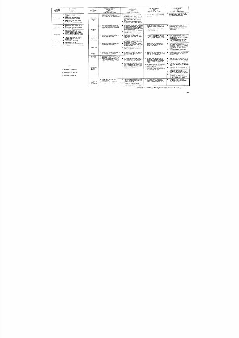
In the succeeding paragraphs of this section_ a brief description is given of the
purpose of each Little Joe H/Apollo launch (Figure 1-9), the configuration of the
vehicle (Figure 1-10) and a summary of the flight events and results (Figure 1-11).
More detailed descriptions of the vehicles and flight performance are given in Volume
II of this report.
i-II

8/6/2019 Little Joe II Test Launch Vehicle NASA Project Apollo. Volume 1 Management
http://slidepdf.com/reader/full/little-joe-ii-test-launch-vehicle-nasa-project-apollo-volume-1-management 21/157
ALTITUDE, FT l
_'= 120KI-=bO
DESIRED TEST REGIONk_J-JJ
100K ® NOMINAL TEST POINT
A ACTUAL TEST POINT
'_" ACTUAL TEST PATH
80K
3
70K
_OK
Co:LU
0'_ .40K
- 12 -51-1 --
12-50-2,
1
12-50'1 _, co-_
1OK i
O0 lOO 200 300 400 500 600 700 800 900 lOOO
DYNAMIC PRESSURE, q - LBS/FT 2 C-,(,O6Z-S
Figure 1-8. LJ-]I/Apollo Abort Test Regions
8/6/2019 Little Joe II Test Launch Vehicle NASA Project Apollo. Volume 1 Management
http://slidepdf.com/reader/full/little-joe-ii-test-launch-vehicle-nasa-project-apollo-volume-1-management 22/157
POWER-ON TUMBLING
HIGH D_NAMIC PRESSURE MAXIMUM DYNAMIC HIGH ALT TUDE ABORT BOUNDARY ABORTQUALIFICATION APOLLO TRANSONIC ABORT PRESSURE ABORT A-D03 ! A-D04
LITTLE JOE II TEST VEHICLE DEVELOPMENT A-O01 A-O02 BOILERPLATE 22 S/C 0 02DEVELOPMENT (QTV) ISSUES BOILERPLATE 12 BOILERPLATE 23 LJ-II12-51-2 LAUNCH VEHICLE
ISSUES 12-50-1 LJ-If12-50-2 LAUNCH VEHICLE LJ-II12-51-i LAUNCH VEHICLE , LJ-II12-51-3 LAUNCH VEHICLEI
• DEMONSTRATE CAPABILITY TO PERFORM • DEMONSTRATE THE C APABILITY OF THE • DEMONSTRATE SATISFACTORY LEV P ER- • DEMONSTRATE SATISFACTORY LEV p ER- • DEMONSTRATE SATISFACTORY LEV P ER-
THE LAUNCH TRAJECTORY FOR MISSION ESCAPE SYSTEM TO PROPEL THE CM FORMANCE UTILIZING THE CANARD SUB- FORMANCE AT AN ALTITODE APPROXlMA- FORMANCE FOR AN ABORT INTHE POWER-
A-O01 SAFELY AWAY FROM THE LAUNCH VEHICLE SYSTEM AND BOOST PROTECTIVE COVER, TING THE UPPER LIMIT FOR THE CANARD ON TUMBLI NG BOUNDARY REGIONAND TOVERIF Y TH E ABORT CAPABILITY IN SUBSYSTEM
• DEMONSTRATE A BI LI TY OF LAUNCH CAPABILITY THE MAXIMUM DYNAMIC-PRESSURE REGION
PERFORMANCE VEHICLE TO CLEAR THELAUNCHER (TO ABORT) WITH CONDITIONS APPROXIMATING EDS
• DEMONSTRATE ALGOL THRUST TERMI- LES LIMITS
NATION SYSTEM • DETERM INE THE PERFORMANCE OF THE
• DEMONSTRATE FUNCTIONAL AND STRUC- LEV IN THE MAXIMUM DYNAMIC PRESSURE
TURALADEQUACY OFGSE REGION
• DEMONSTRATE THAT FINSARE FLUTTER • DETERMI NE AERODYNAMIC STABILITY • DEMONSTRATE SAT SFACTORY LEV POWER- • DEMONSTRATE ORIENTATION OF THE LEV • DEMONSTRATE THE CAPABIL ITY OFTHE
FREE CHARACTERISTICS OF THE ESCAPE CON- ON STABILITY FOR ABORT IN THE MAXIMUM TO AM AIN HEAT SHIELD FORWARD ATTI- CANARD SUBSYSTEM TO SATISFACTORILY
INTEGRITY • DEMONSTRATE STRUCTURAL INTEGRITY FIGURATIO N FOR THIS ABORT CONDITION DYNAMIC PRESSURE REGION WITH CONDI- TUDE I REORIENT AND STABILIZE THE LEVHEATTIONS APPROXIMATING EMERGENCY DETEC- SHIELD FORWARD AFTER A POWER-ON
FOR MISSION A-D01 STABILITY TION SUBSYSTEM LIMITS • DETERMINE THE DAMPING OFT HE LEV TUMBLING ABORT
• DEMONSTRATE ADEQUACY OF PROCEDURE LEV OSCILLATIONS WITH THE CANARD SUB-FOR WIN D C OMPENSATION BY AIMING • DEMONSTRATE SATISFACTORY CANARD DE- SYSTEM DEPLOYED ,
LAUNCHER IN AZIMU TH A ND E LE VATION PLOYMENT, LEV TURN-AROUND DYNAMICS,,AND MAIN HEAT SHI EL D FORWARDFLIGHT
• EVALUATE TECHNIQUES AND PROCEDURES ! STABIL ITY PRIORTO LES JETTISONPROCEDURES WHICH CONTRIBUTE TOEFFICIENT LAUNCH
OPERATIONS • DEMONSTRATE THE STRUCTURAL INTEG- • DEMONSTRATE THE S TRUCTURAL PER- • DETERMINE THE PHYSICAL BEHAVIOR OF • DEMONSTRATE THE STRUCTURAL INTEG-
• EVALUAT E P ROCEDURESFORGROUND RITY OF THE ESCAPE TOWER FORMANCE OFTHE LES W ITH THE CANARD THE BOOST PROTECTIVE, C OVER DURING RITY OF T HE LEV AIRFRAME STRUCTURE
COMMAND ABORT FOR APPLICATION TO INTEGRITY SUBSYSTEM LAUNCH AND ENTRY FRIOMHIGH ALTITUDE BOUNDARyFORN ABORTREGIoNINHE POWER-ON TUMBLINGMISSION A -O01 (STRUCTURAL • DEMONSTRATE THE STRUCTURAL PER-
PERFORMANCE) FORMA NC E O F T H E B OO ST P RO TE CTIVE • DEMONST RA TE T HE S TR UC TU RA L C AP A-
• DETERMINE BASE PRESSURES COVER DURING AN ABORT INTHE MAXIMUM BILIT Y O F T H E P RO DU CT IO N B PC T O
ENVIRONMENT • DETERMINE BASE HEATING DYNAMIC P RE SS UR E R EG IO N WITHSTAND THE LAUNCH ENVIRONMENT
• DETERMINE FLEXIBLE BODY RESPONSE OF • DEMONSTRATE SATISFACTORY RECOVERY • DEMONSTRATE SATISFACTORY SEPARA- • DEMONSTRATE JETTISON OF THE LES • DEMONSTRATE THE CAPABILITY OF THE
TOTAL LAUNC H VEHICLE PLUS PAYLOAD TIMING SEQUENCE IN THE ELS TIO N O F T HE L ES P LU S B OO ST P RO TE CTIVE PLUS BOOST PROTECTIVE COVER AFTER CM FORWARD HEATSHIELD THRUSTERS TO• COVER FROM THE CM HIGH ALTITUDE ENTRY SATISFACTORILY SEPARATE THE FORWARD
HEATSHIELD AFTER THE TOWER HAS BEEN
*_ SEPARATION • DEMONSTRATE SATISFACTORY SEPARA- JETTISONED BYTHE TOWER JETTISONTION OFTHE LEV FROMTHE SM AT AN "MOTOR
ANGLE OF ATTACK • DEMONSTRATE SAT]SFACTORY SEPARA-
TION OFTHE LEV FROMSM
• DEMONSTRATE PROPER OPERATION OFTHE • D EMONSTRATE SAT ISFACTORY OPERATION • D EMONSTRATE PER FORMANCE OF THE ELS • DEMONSTRATE SATISFACTORY OPERATION. .. .. .. .. .. .. .. .. .. . , ,, ,,,_ Hci_,_TU_ TWO-POINT HARNESS ATTAP_-L AND PERFO RM ANC E O F THE EL S W ITH ARECOVERY CM-SM SEPARATION SUBSYSTEM _i_u rr-RruR,v,_,_,_-r ,nEELS vS,,,_ ...................
ELS REEFED DUAL DROGUES VENT FOR THE MAIN PARACHUTES SPACECRAFT VEHICLE
SEQUENCE • DEMONSTRATE PROPER OPERATION OF T HE(OF EVENTS) APPLICABLE COMPONENTS OF THE ELS
• DETERMINE AERODYNAMIC LOADS DUE TO • DETERMINE THE CM PRESSURE LOADS, • OBTAIN DATA ON THERMAL EFFECTS • DETERMINE THE S TATIC LOADS ON THE CM
LOCAL SURFACE PRESSURES ONTHE CM INCLUDING POSSIBLE PLUME IMPINGEMENT DURING BOOST ANDDURINGIMPINGEMENT DURING LAUNCH ANDTHE ABORT SEQUENCE
ANDSM DUR INGA L ITTLE JOE II LAUNCH IN THEMAXIMUM DYNAMIC PRESSURE OF THE LAUNCH ESCAPE MOTOR PLUMES • DETERMINE THE DYNAM IC LOADING ON THE
REGION ON THE CM AND THE LAUNCH ESCAPE CM INNER STRUCTURETOWER
• DETERM IN E THE AERODYNAMIC PRESSURE • DETERMINE THE DYNAMIC LOADS AND THELOADS ONSM DURING THE LAUNCH PHASE • DETERMINE PRESSURES ON THE C M BOOST STRUCTURAL RESPONSE OFTHE SM DURING
PROTECTIVE COVER DURING LAUNCH AND LAUNCHLEGEND • OBTAIN THERMAL EFFECTS DATA ON THE HIGH ALTITUDE ABORT
CM DURING AN ABORT INTHE MAXIMUM • DETERMINE THE STATIC PRESSURES IV-ENVIRONMENT DYNAMIC PRESSURE REGION • DETERMINE VIBRATION AND ACOUSTIC POSED ON THE CM BYFREE STREAM CON-
(EFFECTS ENVIRONMENT AND R ESPONSE OF THE S M DITIONS AND LES MOTOR PLUMES DURING
• FI RST-ORDER TEST OBJECTIVE INDUCED) WITH SIMULATED RCS QUADS A POWER-ON TUMBLING ABORT
• OBTAIN DATA ON THE STRUCTURAL RE-
• SECOND-ORDER TEST OBJECTIVE SPONSE OF THE CM DURING ELS SEQUENCE
• OBTAIN THERMAL DATA ON THE BPC DUR-
• THIRD -ORDER TEST OBJECTIVE ING A POWER-ON TUMBLING ABORT
• OBTAIN ACOUSTICAL NOISE DATA INSIDETHE CMAT AN ASTRONAUT STATION
• D EMONSTRATE L IT TL E JOE i I- S/C • DEMONSTRATE SATISFACTORY PERFORM- • DELIVER THEAPOLLO BblLERPLATE • DELIVER THE APOLLO SPACECRAFT TO
L ITTLE JOE II/ COMPATIBILITY ANCE OFTHELAUNCHVEHICLE ATTITUDE SPACECRAFT TO THE DI_SIRED CONDI- THE DESIRED CONDITIONS FOR DEMON-
APOLLO • DELIVER THE A POLLO BOILERPLATE CONTROL SUBSYSTEM TIONS FOR DEMONSTRA_FION OFTHE LEV STRATION OFTHE LEV
COMPATIBILITY SPACECRAFT TO THE DESIRED CONDI- • DELIVER THE APOLLO BOILERPLATET IO NS F OR DEMONS TRA TI ON OF T HE LE V S PACECRA FT T O THE DE SI RE D CONDI-
TIONS FOR DEMONSTRATI ON OFTHE LEV
C-60b2Al'
Figure 1-9. WSMR Apollo Flight Program Mission Objectives
1-13

8/6/2019 Little Joe II Test Launch Vehicle NASA Project Apollo. Volume 1 Management
http://slidepdf.com/reader/full/little-joe-ii-test-launch-vehicle-nasa-project-apollo-volume-1-management 23/157
APOLLOMISSION - NUMBER QTV A-D01 A-O02 A-O03 A-OO4
- LAUNCHWEIGHT (LBS) 57, 165 57,930 94,331 177,189 13% 731
PAYLOAD - NUMBER DUMMY CSM BP-12 BP-23 BP-22 SC-002MOCKUPLES
-WEIGHT (LBS) 24,225 25,335 27, b92 27,836 23_ 185
- BALLAST (LBS) 9,361
LAUNCHVEHICLE - NUMBER 12-50-1 12-50-2 12-51-1 12-51-2 12-51-3
SYSTEM CONFIGURATION
AIRFRAME -WEIGHT INC. MOTORS(LBS) 32,941 . 32,595 58,030 144,309 101,328
- BALLAST (LBS) - 8,609 5,044 5.,867- FIXED FIN X' X
- CONTROLLABLEFIN X X X
PROPULSION - 1ST STAGERECRUIT 6 6 4 5
- IST STAGE ALGOL ). i 2 3 2
- 2NDSTAGEALGOL 3 2
ATTITUDE CONTROL - PITCH PROGRAMMER X X X
- PITCH-UP CAPABILITY X X
- SIGNALFILTER-2ND ORDER X X X
- SIGNAL FILTER-NOTCH X X
- REACTIONCONTROL X X
- AERODYNAMICCONTROL X X X
- ELEVONACTUATORHYD.
SUPPLY SINGLE DUAL DUAL
RF COMMAND - RANGESAFETY DESTRUCT X X X X
- THRUST TERM & ABORT X
- PITCH-UP & ABORT X X
- ABORT X X
ELECTRICAL - PRIMARY X X X
- INSTRUMENTATION X X X
LOCATED LOCATED
INSTRUMENTATION -RFTRANSMITTERS 3 IN 2 IN 1PAYLOAD PAYLOAD
- TM MEASUREMENTS 66 3 5B 13 39
- LL MEASUREMENTS 24 24 .37 45 36
RADARBEACON - LAUNCHVEHICLE X
- PAYLOAD X X X X
C-6062-I0
Figure 1-10. Launch Vehicle Configuration Summary
1-15
8/6/2019 Little Joe II Test Launch Vehicle NASA Project Apollo. Volume 1 Management
http://slidepdf.com/reader/full/little-joe-ii-test-launch-vehicle-nasa-project-apollo-volume-1-management 24/157
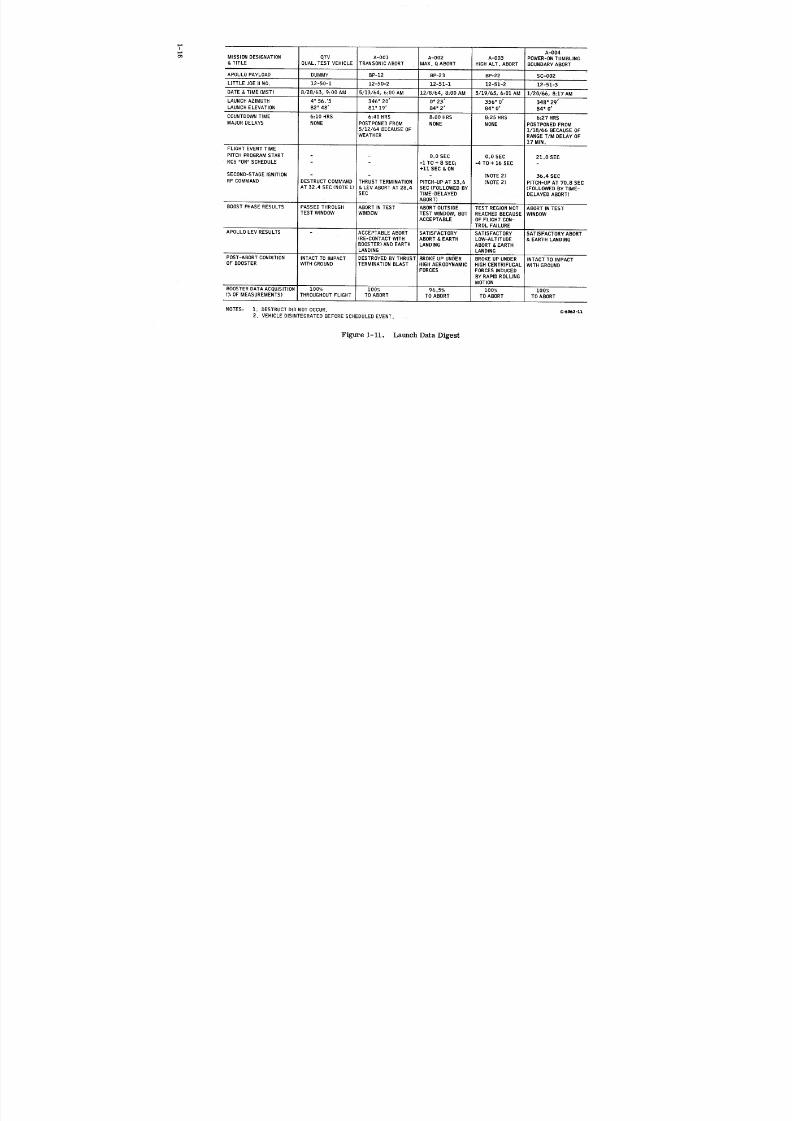
IFL A-OO4
o'_ MISSION DESIGNATION QTV A-O01 A-O02 A-O03 POWER-ON TUMBLING
& TITLE QUAL. TEST VEHICLE TRANSONIC ABORT MAX. Q ABORT HIGH ALT. ABORT BOUNDARY ABORT
APOLLO PAYLOAD DUMMY BP-12 BP-22, BP-22 SC-002
LITTLE JOE II NO. 12-50-1 12-50-2 12-51-1 12-51-2 12-51-3
DATE & TIME (MST) 8/28/65, 9:00 AM 5/13/64, 6:00 AM 12/8/64, 8:00 AM 5/19/65, 6:01 AM 1/20/66, 8:17 AM
LAUNCH AZIMUTH 4° 56.'5 2,46 ° 20' D° 25" 356" O' 348 = 29'
LAUNCH ELEVATION 82 = 48' 81 ° 19' 84 ° 2' 84" O' 84 ° O'
COUNTDOWNTIME 6:10 HRS 6:40 HRS 8:00 HRS 8:25 HRS 6:27 HRS
MAJOR DELAYS NONE POSTPONED FROM NONE NONE POSTPONED FROM
5/12/64 BECAUSE OF 1/18/66 BECAUSE OF
IWEATHER RANGE T/M DELAY OF
17 MIN.
FLIGHT EVENT TIME
PITCH PROGRAMSTART - 0.0 SEC 0.0 SEC 21.0 SEC
RCS "ON" SCHEDULE - -1 TO+ 8 SEC; -4 TO + 16 SEC -
+11 SEC & ON
SECOND-STAGE IGNITION (NOTE 2) 36.4 SEC
RF COMMAND DESTRUCT COMMAND THRUST TERMINATION PITCH-UP AT 33.6 (NOTE 2) PITCH-UP AT 70.8 SECAT 32.4 SEC (NOTE 1) & LEV ABORT AT 28.4 SEC (FOLLOWED BY (FOLLOWED BY TIME-
SEC TIME-DELAYED DELAYED ABORT)
ABORT)
BOOST PHASE RESULTS PASSED THROUGH ABORT IN TEST ABORT OUTSIDE TEST REGION NOT ABORT IN TEST
TEST WINDOW WINDOW TEST WINDOW, BUT REACHED BECAUSE WINDOWACCEPTABLE OF FLIGHT CON-
TROL FAILURE
APOLLO LEV RESULTS ACCEPTABLE ABORT SATISFACTORY SATISFACTORY SATISFACTORY ABORT
(RE-CONTACT WITH ABORT & EARTH LOW-ALTITUDE & EARTH LANDING
BOOSTER) AND EARTH LANDING ABORT & EARTH
LANDING LANDING
POST-ABORT CONDITION INTACT TO IMPACT DESTROYED BY THRUST BROKE UP "UND"ER BROKE UP UNDER INTACT TO IMPACT
OF BOOSTER WITH GROUND TERMINATION BLAST HIGH AERODYNAMIC HIGH CENTRIFUGAL WITH GROUND
FORCES FORCES INDUCED
BY RAPID ROLLING
MOTION
BOOSTER DATA ACQUISITION 100% 100% 96.5% 100% 100%
(%OF MEASUREMENTS) THROUGHOUT FLIGHT TO ABORT TO ABORT TO ABORT TO ABORT
NOTES: 1. DESTRUCT DID NOT OCCUR. c-6062-11
2. VEHICLE DISINTEGRATED BEFORE SCHEDULED EVENT.
Figure 1-11. Launch Data Digest
8/6/2019 Little Joe II Test Launch Vehicle NASA Project Apollo. Volume 1 Management
http://slidepdf.com/reader/full/little-joe-ii-test-launch-vehicle-nasa-project-apollo-volume-1-management 25/157
The first two launch vehicles were alike with respect to configuration and mission
profile. Both were fixed-fin vehicles, dependent upon the inherent stability of the
total vehicle to achieve a successful ballistic trajectory to the test region. One Aero-
jet-General Algol and six Thiokol Chemical Co. Recruit solid-propellant rockets made
up the propulsion package. The Algol 1D, Mod 2 sustainer motor provided an average
sea-level thrust of 96,530 lbs for 42.1 seconds, with a peak thrust of 116,600 lbf.
Each Recruit TE-29-II, Mod. 1B booster rocket was rated at 37, 1O0 lbf at sea leveland was expended approximately 1.5 seconds after ignition.
The principal difference between the QTV and A-001 vehicles was that the QTV had/
a dummy payload which did not separate from the launch vehicle in flight as did the
BP-12 payload on the A-001. The QTV (Vehicle 12-50-1} made a successful flight,
passing through the test "window, as shown in Figure 1-8. All objectives weresatisfied (Figure 1-9), except for the WSMR Command Destruct subsystem. The i
destruct signal was received and detonated the safe-and-arm unit; however, the prima-
cord did not propagate the detonation to the shaped charges on the Algol case.
Mission A-001 -- Launch Vehicle 12-50-2 successfully boosted the Apollo boiler _plate (BP-12} to the planned test region. Upon command from the ground the LEV
separated from the booster. At a preset altitude, the escape tower was jettisoned
from the command module. Following this was the parachute deployment and landing
of the command module. The vehicle was equipped with a dual RF command thrust
termination subsystem as an aid to LEV separation at high subsonic speed. Because
the abort test point was reached while the Algol motor was developing high thrust,
clean separation of the LEV under such conditions would not be possible. For this
reason the thrust was terminated (via ground radio command} by splitting the motor
case. The ground-initiated command to terminate thrust and initiate the LEV abort
was based on elapsed flight time, which proved to be accurate enough to achieve the
desired test conditions.
The remaining three launch vehicles, Nos. 12-51-1, -2, and-3, incorporated
flight controls. While the attitude control systems (ACS} for all three were of the same
basic type, they differed in some details, as summarized in Figure 1-10. Common to _
all was: 1) an autopilot to provide sensing (attitudes and rates for three axes}, logic,
and control commands, and 2} hydraulically actuated aerodynamic controls. Vehicles
12-51-1 and -2 included reaction controls, operating on a preset schedule, in parallel
with the aerodynamic controls. These reaction motors, fueled by 90% hydrogen
peroxide, were mounted in back-to-back pairs at the root of each fin. Thrust termi-
nation was not used on any of these vehicles, not being needed to assure clean separa-
tion of the LEV.
Mission A-002 -- With simultaneous ignition of two Algols and four Recruits,
Vehicle 12-51-1 boosted the Apollo BP-23 to a high dynamic pressure abort. A
pitch programmer caused the vehicle to pitch down at a constant rate, starting at lift-
off, such that the vehicle would, at the test point, approximate the Saturn flight path
angle as well as Mach number and dynamic pressure. At the predetermined flight
conditions, as given by a real-time display system (RTDS}, a signal was transmitted
by radio link to the launch vehicle, commanding a pitch-up maneuver.
1-17
8/6/2019 Little Joe II Test Launch Vehicle NASA Project Apollo. Volume 1 Management
http://slidepdf.com/reader/full/little-joe-ii-test-launch-vehicle-nasa-project-apollo-volume-1-management 26/157
At LEV abort time, the pitch-up maneuver approximated the limits of the proposed
Saturn Emergency Detection Subsystem (EDS). As a result of an error in the RTDS
meteorological data, the pitch-up command was transmitted 2.4 seconds early. This
produced an abort of the LEV at a dynamic pressure 25 percent greater than planned,
but at the correct Mach number.
Because the launch escape system stiffness and mass distribution differed fromthe mathematical model used for design, the autopilot filters were not able to prevent
coupling of the fundamental structural bending mode with the attitude control subsystem.
The resulting elevon oscillation, although it had no noticeable effect on the vehicle
stability or flight path, excessively depleted the hydraulic fluid supply and pressure.
The lowered pressure reduced the elevon hinge-moment capability such that the planned
angle of attack at LEV abort time was not fully attained. Despite the noted departures
from the mission plan, the LEV exceeded the desired conditions from which a success-
ful recovery and landing were made. Indeed the extra high dynamic pressure abort pro-
vided a demonstration of structural integrity of the LEV at near-limit load.
Mission A-003 -- This mission was scheduled to demonstrate with Apollo BP-22the LEV performance at the upper limit of altitude for the canard subsystem and the
ability of the subsystem to orient the LEV With its main heat shield forward. Launch
Vehicle 12-51-2 had a propulsion system of six Algol motors, fixed in two stages
of three each. The autopilot was augmented with a set of new filters, designed to block
the feedback of the first bending mode to the elevon control which occurred on the
previous flight. Also, the pitch-up function was deleted, not being required for this
mission.
Very shortly after lift-off the vehicle began an uncontrolled roll which accelerated
with increasing velocity of flight; prior to second-stage ignition and while still at low
altitude, the launch vehicle disintegrated. The break-up severed the abort "hot lines,"resulting in initiation of the LEV escape sequence. Despite this severe "test," the LEV
performance was excellent. The command module was recovered, together with useful
data.
Mission A-004 -- Demonstration of satisfactory LEV performance and of structural
integrity of an Apollo spacecraft for abort in the power-on tumbling boundary region
were the primary objectives of Mission A-004o Launch Vehicle 12-51-3 boosted Apollo
SC-002 on this mission with excellent results. The motor configuration was two Algols
and five Recruits for first stage and two Algols for second stage. (The second-stage
firing phase constituted the first time the Algol motor had been ignited at altitude, and
was successful.) The attitude control system of Vehicle 12-51-3 differed from that ofVehicle 12-51-2 in two major respects: the reaction control subsystem was deleted,
not being required for this mission, and the pitch-up function was installed. Also, the
pitch program was preset to commence 20 seconds after lift-off.
1-18

8/6/2019 Little Joe II Test Launch Vehicle NASA Project Apollo. Volume 1 Management
http://slidepdf.com/reader/full/little-joe-ii-test-launch-vehicle-nasa-project-apollo-volume-1-management 27/157

8/6/2019 Little Joe II Test Launch Vehicle NASA Project Apollo. Volume 1 Management
http://slidepdf.com/reader/full/little-joe-ii-test-launch-vehicle-nasa-project-apollo-volume-1-management 28/157
2 PROJECT PHILOSOPHY

8/6/2019 Little Joe II Test Launch Vehicle NASA Project Apollo. Volume 1 Management
http://slidepdf.com/reader/full/little-joe-ii-test-launch-vehicle-nasa-project-apollo-volume-1-management 29/157
2 PROJECT PHILOSOPHY
A. MANAGEMENT
The Request for Proposal directed the Contractor to establish a strong I_JII
organization, headed by a Program Manager and removed from other Contractor pro-
grams to the extent necessary to prevent interference with a timely completion of the
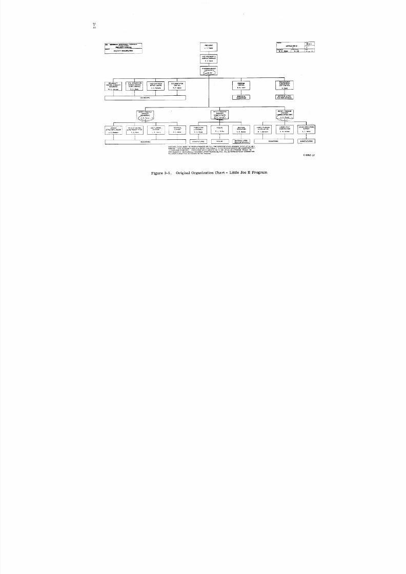
Apollo program. To achieve this, a modified project organization was proposed and
initiated as shown in Figure 2-1. The philosophy of this type of organization was thatproject key supervisors and staff members reported functionally to the Program Man-
ager but administratively to their home group or department. They responded to the
project line organization, to each other and to direction from the Program Manager to
integrate and accomplish the tasks of the project. In addition, there remained a link
of responsibility with the home group or supervisor to ensure that high quality design
or manufacturing operations were achieved, proper procedures were followed and
schedule requirements were met. The assignment of talented senior personnel to the
project was one of the principal reasons for its ultimate success.
Personnel were transferred into the project as tasks required and were promptly
returned to their home department upon the completion of their tasks. This ensureda supply of top-grade people, continuity of experience and a minimum number of people
on the project as required by the tasks. This variation of personnel with work load is
reflected in Section 4 and is shown in more detail in the sample of manpower applica-
tion in 1964, also in Section 4.
Except for minor personnel changes, the organization shown in Figure 2-1 applied
until June 1965. At that time, the primary design task had been accomplished and
Engineering and Launch Operations activity were grouped under one head to recognize
the re-emphasis on test and the necessity for even more closely integrated operations
during this period. The revised organization is shown in Figure 2-2.
The organization was designed to include elements that were required on a full-
time basis. Part time support from other Convair departments and groups, as re-
quired, was assured on an as-required basis by identifying the individual in that
department who would represent the department or group and had the responsibility of
providing the support when requested. This method of identification of "contact
people" is shown in Figure 2-3.
2-1
8/6/2019 Little Joe II Test Launch Vehicle NASA Project Apollo. Volume 1 Management
http://slidepdf.com/reader/full/little-joe-ii-test-launch-vehicle-nasa-project-apollo-volume-1-management 30/157
t'OI
I--I_-A-|
VICE FT_ES_DENT&
GEm£RAL MANAGER
R, A,Nelle
IPROGRAMM _AG_R
I I i I I IRELIABILITY SVS. INTEGRATION NASA SAN OIEGO DOCUMENTATION PflG¢;RAM SUBCONTRACT
CONTROL & QUALITY CHANGE CONTROL OFFICE LIAISON CONTROL C(_I TROL COST C0_TROL
ASSURANCE PLANS CONTROL B.E. Ca_,. N, G ra n_w. L , ohnst_ D.G . M o_y H G. S_¢¢ W.F. Bm*_
I I lDEPUTY PROGRAM 0EPUTY I>ROGRAM DEPUTY pROGRAM
MANAGER MANAGER MANAGER
, Tu_ le
I [ I I [ t I II LAUNCH OPERATIONS
R, E, M al= IVEHICLE VEHICLE CONTROL GSE PLANNING TECH_'/_CAL FABRICATION TOOLING I MATERIAL LAUNCH OLANNINC LAUNCH TEST A.C. 0chief
ST RU CTURA LOESIG N & I NSTRUMEN TATION & DESIGN SUPPORT _,ASSEMBLY OPERATIONS & EVALUATION COORDINATION SUPPORT
- J.E. Bu_son J K. Lessl_ N. L We_r C. S Stran_ 0 L. Hunle_ A. R _ M, L Edelste,n A. W. K el ogg
i
' ' [ ]1 [[ I[ 1PERSONNEL SHOWN UNDERTHE PROGRAM MANAGER ARE FULL-TIME REPRESENTATIVES ASSIGNED TO THE LrtT L£ J OE IIPROORAM. THESE REPRESENTATIVES WILL REPORT FUNCTIONALLY TO THE PROGRAMMANAGER ¢dNOADMINISTRA'FIVELYTO THEIR HOMEDEPARTMENT OTHER DEPARTMENTS CONTRIBUTING TO THE LITTLE JOE II ,_ROGR_M THROUGH THEPERFORMANCE OF THEIR NORMALLY-ASSIGNED SUPPORT RESPONSISIUTIES, WILL BE REPRESENTED BY COOROINATORS
WHO SPEi_O AS '_UCHTI_E AS REQUIREO ON TH_S PROGRAM.
C-bOb2-12
Figure 2-1. Original Organization Chart- Little Joe IT Program

8/6/2019 Little Joe II Test Launch Vehicle NASA Project Apollo. Volume 1 Management
http://slidepdf.com/reader/full/little-joe-ii-test-launch-vehicle-nasa-project-apollo-volume-1-management 31/157
I FORM32ONE GENERALOYIIAMIC/CONVAIR I APP_ROVED: PMNO.
,,_o..o.<.<,FoG,. .,._,, f*'¢/..'_2,-A-S
PR(X;RAMMANUAL I J.R. 9emp_y PROGRAMMNIAGER b*ROGRAM: LITTLE JOEII PREPARED8Y OATIE 1 OF 1
SUBJECT! PROGRAMORGANIZAT ION [ C,H . Helm 6-7-bS
I vICE PRESIDENT
A/C PROGRAMS
.LH . Fm
I
I DIRECTOR
PROGR_I M_T.AIRCRAFT
I
I PROGR_ U#,NAGEE1
I I I I I I I I
CTL & QUAL. CHANGECONTROL OFFICELIAISON CONTROL CON'i_ROL ADMh_ISTRATOR SUBCONTRACT SPAREEASSURANCE pLANSCONTROL CONTROL
W. L..lahnlcem R. Pit, ms V.J. Pad( R.C. _lel 8. E. C4,dn C.W. Pamw N. Grind W.D. Bame
: ; ; ; ; ;
I REL'A°UT* CONTRAC'S' PROG'P_--°ONT"CT"--ER'A"l "V'_ IOIiTROL COML. SALES & CONTROL COML.SALES PROD.SERVICEE PARTS
I I
I DEPUTYPROGRAMG,°T,_OGRAM _ANAGE MANGER
ENGR, &01_.
'--4- _I I i I I I 1 |
MANAGER FABRICATION ILAUNCHPLNG. VEHICLECONTROL GSEpLANNING TECHNICAL OFF-SITE TOOLING
&EVALUATION & IqSTRUMENTATION & DESIGN SUPPORT OPERATIONS & ASSEMBLY O.L. H uRley
I. I . E delsLein R. X, ,k_m'ml J.K. L esslq N.L. _ A.W. Kella._ A .C. Oe_kx
: ; ; : [ ; ;
ENG,,EERI,_ I I ] MANUFACTURING I I TOOLING IQUAL.CTL. [ MANUFACTURING ENGINEERING
ADMINISTRATION &INSPECTION SUPPORT
PERSONNELSHOWNUNDERTHEPROGRAMMANAGERAREFULLTIMEREPRESENTATIVES I A. W, Kellc_lgASSIGNEDTOTHELITTLEJOEI I PROGRAM.THESEREPRESENTAT IVESWILLREPORT W. W* Fe_lton W.E. _/,/ifl_ltO O.L. TO(I(FUNCTIONALLYTO THEPROGRAMMANAGERANDADMINISTRATIVELYTOTHEIRHOME
DEPARTMENT, OTHERDEPARTMENTSCONTRIBUTINGOTHELITTLE JOEII PROGRAM r : ; :
HROOG.EOERFGRMANOEFTHEIRORML*S'°NEDSU_OORESPONSIBILITIES] RELIA"ILIT*I IILL EE REPRESENTEDBYCOORDINATORSHOSRENDASMUCHTIMEASREQUIREDON ENGINEERING CONTRO MANUFACTURING ENGINEERINGTHISPROGRAM.
C-6062-13
L'_I
Figure 2-2. FinalOrganizationChart - LittleJoe ]IProgram
8/6/2019 Little Joe II Test Launch Vehicle NASA Project Apollo. Volume 1 Management
http://slidepdf.com/reader/full/little-joe-ii-test-launch-vehicle-nasa-project-apollo-volume-1-management 32/157
miNiMAl. IDYNIM_Iq_I m. 12-A-2 ,pus 10"_.lmt_ le _ | e_ Z
Coewmk'OAHs/on _ C.H.Hahn ere¢©TM12117165
PROGRAM MANUAL - LITTLE JOE II _w.,.
MInT KEY DEPARTMENTAL CONTACTS ' MO_AM_N_V
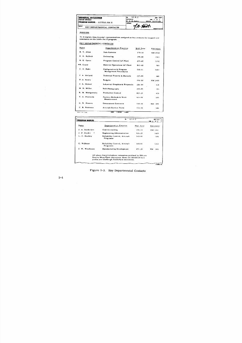
PURPOSE
To degignate departmental repre0entatives assigned as key contacte for support and
assistance on the Little Joe IIprogram.
KEY DEPARTMENTAL CONTACTS
Name Department or Function Mail Zone Extension
B. V. Allen DataSystemt 170-1g KM 3728
R, R. Bullock Estimating 195-40 1561
B. E. Cavin Program Control LF Plant 210-40 12_2
*N. Grand Material Operations LF Plant 847-40 583
C. H. H_.hn CortIigure.tlon k Program t70-31 14O7
Management Procedure0
J. A. Holland Technical Reports & Manuall 227-00 4g)
P. S. Kenny Budgets lq4-00 KM 2481
J. L. Hoover Industrial Graphics& Propolals 226-00 428
M. H. Miller Still Photography 225-00 715
R. M. Montgomery Production Control B21-20 453
V. A. Petricola Factory Methods l, Work 423-00 60_Measurement
C. W, Powers Government Contracts I10-10 KM 891
C. B. Robinson Aircraft Service Parts ll3-00 588
*oo41L.t. •*,l
l " 12"A") 'lag' 10=_ lROGRAM MANUAL _ z o_ z
Name Department or Function Mail Zone. Extension
J. A. Sanderson Cost Accounting 19]-10 KM lZgl
J. F. Snyder Engineering Administration 52b-20 14i_
L. C. Stuckey Reliability Control. Aircraft 149-01 646
Progran_s
C, Waliman Reliability Control. Aircraft 149-01 1254
Programs
3. W. Woodhouse Manufacturing Development 491-20 KM 806
All above-Ueted telephone extemtions prefixed by KM are
Kearny Mesa Plant extensions; those not identified by a
prefix are Lindbergh Field Plant extensions.
C,_06Z-|4
Figure 2-3. Key Departmental Contacts
2-4
8/6/2019 Little Joe II Test Launch Vehicle NASA Project Apollo. Volume 1 Management
http://slidepdf.com/reader/full/little-joe-ii-test-launch-vehicle-nasa-project-apollo-volume-1-management 33/157
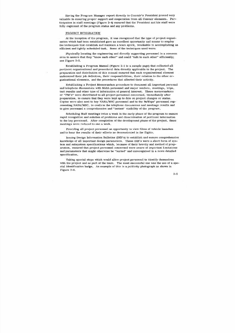
Having the Program Manager report directly to Convair's President proved very
valuable in ensuring proper support and cooperation from all Convair elements. Par-
ticipation in staff meetings (Figure 2-4) ensured that the President and his staff were
fully cognizant of the program status and any problems.
PROJECT INTEGRATION
At the inception of the program, it was recognized that the type of project organi-
zation which had been established gave an excellent opportunity and means to employ
the techniques that establish and maintain a team spirit, invaluable in accomplishing an
efficient and tightly scheduled task. Some of the techniques used were:
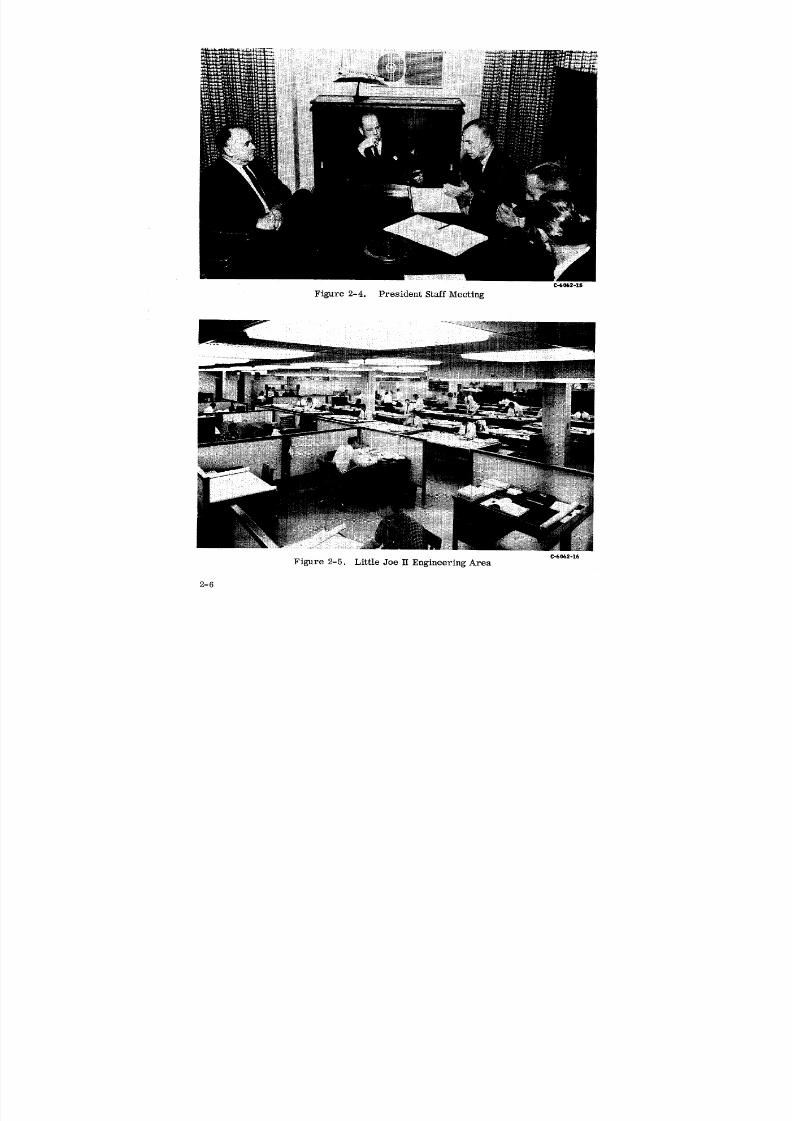
Physically locating the engineering and directly supporting personnel in a common
area to assure that they "knew each other" and could "talk to each other" efficiently;
see Figure 2-5.
Establishing a Program Manual (Figure 2-3 is a sample page) that collected all
pertinent organizational and procedural data directly applicable to the project. Thepreparation and distribution of this manual ensured that each organizational element
understood their job definition, their responsibilities, their relation to the other or-
ganizational elements, and the procedures that affected their activity.
Establishing a Project Memorandum procedure to document all important personal
and telephone discussions with NASA personnel and major vendors, meetings, trips,
test results and other type of information of general interest. These memorandums
or "PM's" were distributed to all project personnel concerned, immediately after
preparation, to ensure that they were kept up to date on project changes or status.
Copies were also sent to key NASA/MSC personnel and to the BuWeps' personnel rep-
resenting NASA/MSC, to confirm the telephone discussions and meetings results andto give personnel a comprehensive and "instant" visibility of the program.
Scheduling Staff meetings twice a week in the early phase of the program to ensure
rapid recognition and solution of problems and dissemination of pertinent information
to the key personnel. After completion of the development phase of the project, these
meetings were reduced to one a week.
Providing all project personnel an opportunity to view films of vehicle launches
and to hear the results of their efforts as demonstrated in the flights.
Issuing Design Information Bulletins (DIB's) to establish and ensure comprehensive
knowledge of all important design parameters. These DIB's were a short form of sys-tem and subsystem specifications which, because of their brevity and method of prep-
aration, ensured that project personnel concerned were aware of important limitations
and parameters that might otherwise be "buried" and unrecognized in a more detailed
specification.
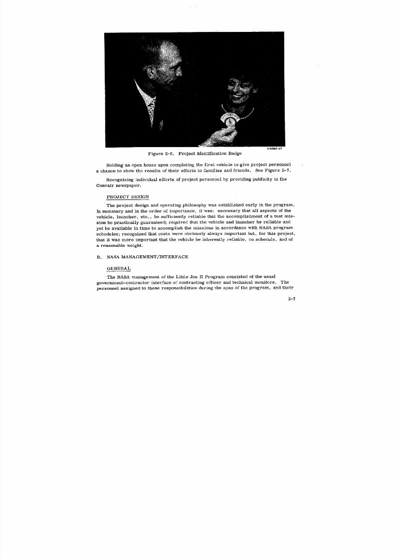
Taking special steps which would allow project personnel to identify themselves
with the project and as part of the team. The most successful one was the use of a spe-
cial identification badge. An example of this is a publicity photograph as shown in
Figure 2-6.
2-5
8/6/2019 Little Joe II Test Launch Vehicle NASA Project Apollo. Volume 1 Management
http://slidepdf.com/reader/full/little-joe-ii-test-launch-vehicle-nasa-project-apollo-volume-1-management 34/157
C-6002-15
Figure 2-4. President Staff Meeting
C-6062-16
Figure 2-5. Little Joe IT Engineering Area
2-6
8/6/2019 Little Joe II Test Launch Vehicle NASA Project Apollo. Volume 1 Management
http://slidepdf.com/reader/full/little-joe-ii-test-launch-vehicle-nasa-project-apollo-volume-1-management 35/157
C-_062-17
Figure 2-6. Project Identification Badge
Holding an open house upon completing the first vehicle to give project personnel
a chance to show the results of their efforts to families and friends. See Figure 2-7.
Recognizing individual efforts of project personnel by providing publicity in the
Convair newspaper.
PROJECT DESIGN
The project design and operating philosophy was established early in the program.
In summary and in the order of importance, it was- necessary that all aspects of the
vehicle, launcher, etc., be sufficiently reliable that the accomplishment of a test mis-
sion be practically guaranteed; required that the vehicle and launcher be reliable and
yet be available in time to accomplish the missions in accordance with NASA program
schedules; recognized that costs were obviously always important but, for this project,
that it was more important that the vehicle be inherently reliable, on schedule, and of
a reasonable weight.
B. NASA MANAGEMENT/INTERFACE
GENERAL
The NASA management of the Little Joe II Program consisted of the usual
government-contractor interface of contracting officer and technical monitors. The
personnel assigned to these responsibilities during the span of the program, and their
2-7

8/6/2019 Little Joe II Test Launch Vehicle NASA Project Apollo. Volume 1 Management
http://slidepdf.com/reader/full/little-joe-ii-test-launch-vehicle-nasa-project-apollo-volume-1-management 36/157
LI OD
8/6/2019 Little Joe II Test Launch Vehicle NASA Project Apollo. Volume 1 Management
http://slidepdf.com/reader/full/little-joe-ii-test-launch-vehicle-nasa-project-apollo-volume-1-management 37/157
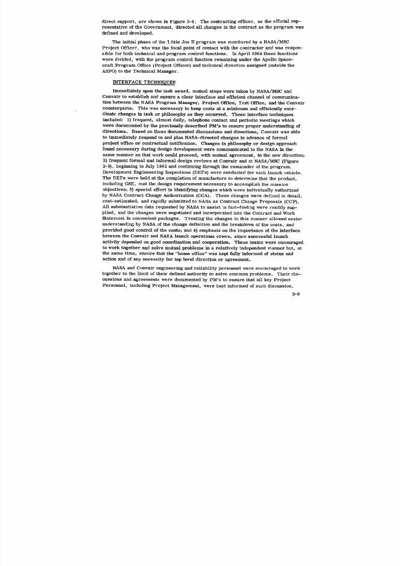
direct support, are shown in Figure 2-8. The contracting officer, as the official rep-
resentative of the Government, directed all changes in the contract as the program was
defined and developed.
The initial phase of the Little Joe H program was monitored by a NASA/MSC
Project Officer, who was the focal point of contact with the contractor and was respon-
sible for both technical and program control functions. In April 1964 these functions
were divided, with the program control function remaining under the Apollo Space-craft Program Office (Project Officer) and technical direction assigned (outside the
ASPO) to the Technical Manager.
INTERFACE TECHNIQUES
Immediately upon the task award, mutual steps were taken by NASA/MSC andConvair to establish and ensure a clear interface and efficient channel of communica-
tion between the NASA Program Manager, Project Office, Test Office, and the Convair
counterparts. This was necessary to keep costs at a minimum and efficiently coor-
dinate changes in task or philosophy as they occurred. These interface techniques
included: 1) frequent, almost daily, telephone contact and periodic meetings whichwere documented by the previously described PM's to ensure proper understanding of
directions. Based on these documented discussions and directions, Convair was able
to immediately respond to and plan NASA-directed changes in advance of formal
project office or contractual notification. Changes in philosophy or design approach
found necessary during design development were communicated to the NASA in the
same manner so that work could proceed, with mutual agreement, in the new direction;
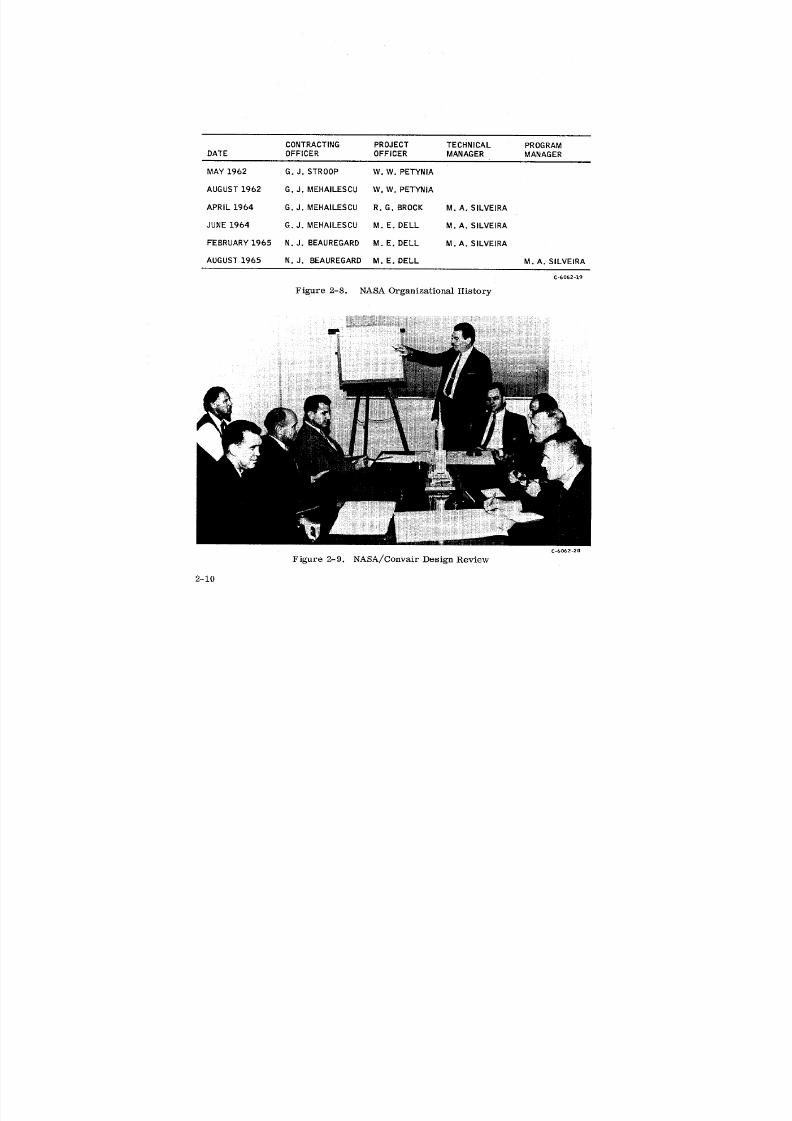
2) frequent formal and informal design reviews at Convair and at NASA/MSC (Figure
2-9), beginning in July 1962 and continuing through the remainder of the program.
Development Engineeering Inspections (DEI's} were conducted for each launch vehicle.
The DEI's were held at the completion of manufacture to determine that the product,
including GSE, met the design requirement necessary to accomplish the mission
objectives; 3) special effort in identifying changes which were individually authorized
by NASA Contract Change Authorization (CCA). These changes were defined in detail,
cost-estimated, and rapidly submitted to NASA as Contract Change Proposals (CCP).
All substantiation data requested by NASA to assist in fact-finding were readily sup-
plied, and the changes were negotiated and incorporated into the Contract and Work
Statement in convenient packages. Treating the changes in this manner allowed easier
understanding by NASA of the change definition and the breakdown of the costs, and
provided good control of the costs; and 4) emphasis on the importance of the interface
between the Convair and NASA launch operations crews, sInce successful launch
activity depended on good coordination and cooperation. These teams were encouraged
to work together and solve mutual problems in a relatively independent manner but, at
the same time, ensure that the "home office" was kept fully informed of status and
action and of any necessity for top level direction or agreement.
NASA and Convair engineering and reliability personnel were encouraged to work
together to the limit of their defined authority to solve common problems. Their dis-
cussions and agreements were documented by PM's to ensure that all key Project
Personnel, including Project Management, were kept informed of such discussion.
2-9
8/6/2019 Little Joe II Test Launch Vehicle NASA Project Apollo. Volume 1 Management
http://slidepdf.com/reader/full/little-joe-ii-test-launch-vehicle-nasa-project-apollo-volume-1-management 38/157
CONTRACTING PROJECT TECHNICAL PROGRAMDATE OFFICER OFFICER MANAGER MANAGER
MAY 1962 G.J. STROOP W.W. PETYNIA
AUGUST 1962 G.J. MEHAILESCU W.W. PETYNIA
APRIL 1964 G.J. MEHAILESCU R.G. BROCK M.A. SILVEIRA
JUNE 1964 G.J. MEHAILESCU M. E. DELL M.A. SILVEIRA
FEBRUARY 1965 N.J. BEAUREGARD M. E. DELL M.A. SILVEIRA
AUGUST 1965 N.J. BEAUREGARD M.E. DELL M.A. SlLVEIRA
C-6062-19
Figure 2-8. NASA Organizational History
C-b062-20
Figure 2-9. NASA/Convair Design Review
2-10
8/6/2019 Little Joe II Test Launch Vehicle NASA Project Apollo. Volume 1 Management
http://slidepdf.com/reader/full/little-joe-ii-test-launch-vehicle-nasa-project-apollo-volume-1-management 39/157
Although it was originally planned by MSC to locatea NASA resident representative
at the Contractor's facility, it was decided that the resident BuWeps representatives at
Convair could adequately represent NASA's interests in engineering, quality control,
contracts and procurement. Due to a well-established, working relationship between
BuWeps and Convair, this method of supporting NASA's interests was very successful.
A form of interface document called the Open Action Log was established early in
the program to identify topics which required action and solution between NASA and
Convair. The Open Action Log was periodically revised to document intermediate
action taken during the problem solution or to define how and when the solution was
achieved; ensured that both parties remained cognizant of the item and the action re-
quirement incumbent upon them, and historically documented the steps taken in solu-
tion of the problem.
C. ENGINEERING
GENERAL
The basic designphilosophyfor theLittleJoe IIemphasized simplicityand relia-
bility.The objectiveswere readilyachieved, sincespace and weightrequirements
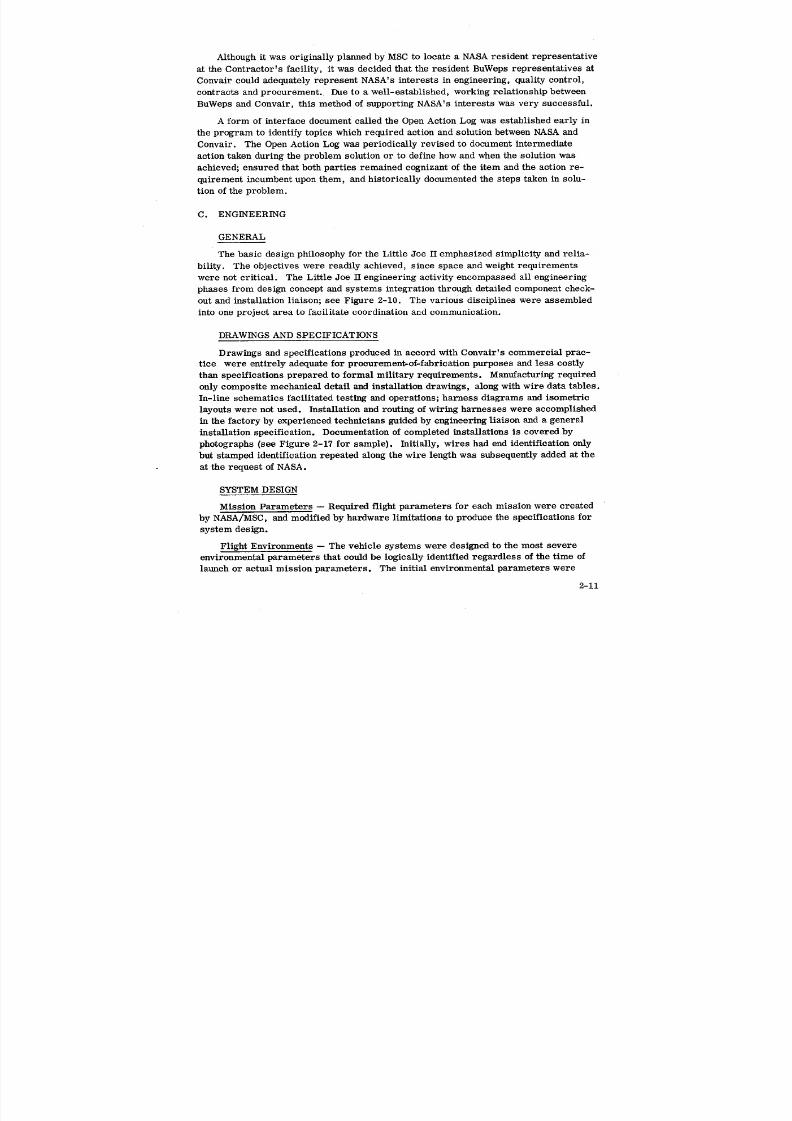
were notcritical.The LittleJoe IIengineeringactivityencompassed allengineering
phases from designconcept and systems integrationthrough detailedcomponent check-
out and installationiaison;see Figure 2-10. The various disciplineswere assembled
intoone projectarea tofacilitateoordinationand communication.
DRAWINGS AND SPECIFICATIONS
Drawings and specifications produced in accord with Convair's commercial prac-
tice were entirely adequate for procurement-of-fabrication purposes and less costly
than specifications prepared to formal military requirements. Manufacturing required
only composite mechanical detail and installation drawings, along with wire data tables.
In-line schematics facilitated testing and operations; harness diagrams and isometric
layouts were not used. Installation and routing of wiring harnesses were accomplished
in the factory by experienced technicians guided by engineering liaison and a general
installation specification. Documentation of completed installations is covered by
photographs (see Figure 2-17 for sample). Initially, wires had end identification only
but stamped identification repeated along the wire length was subsequently added at the
at the request of NASA.
SYSTEM DESIGN
Mission Parameters -- Required flight parameters for each mission were created
by NASA/MSC, and modified by hardware limitations to produce the specifications for
system design.
Flight Environments -- The vehicle systems were designed to the most severe
environmental parameters that could be logically identified regardless of the time of
launch or actual mission parameters. The initial environmental parameters were
2-11
8/6/2019 Little Joe II Test Launch Vehicle NASA Project Apollo. Volume 1 Management
http://slidepdf.com/reader/full/little-joe-ii-test-launch-vehicle-nasa-project-apollo-volume-1-management 40/157
b,3II--,t_
PROJECT>
OFFICE _ PROJECTINTEGRATION
SYSTEMS _ ; CUSTOMERLIAISONINTEGRATION
TECHNICAL INTERFACECOORD.
STAFF-- -- LAYOUT ' /
DRAFT
!
SYSTEM CHECK i i
DESIGN COMPONENTS ! :l =
VENDORLIAISONABM
ATT. CONT. FTI m .=ELECTRICAL TEST SUPPORTIGNITION
LANDINGSLAuNCHER INSTLDRAFTENGR. .I _ ?RANGESAFETY CHECK
.=
RF COMMAND FACILITY LIAISON =' ==
INSTRU. PROCEDURESOCP)T/M TEST AID ENGR. In I mSTRUCT. FTI ,iMECH. INTERFACESPECS iGSE
CHECKOUT- FACTORY IFIELD I I I
DOCUMENTSUPPORTVEHICLEDESC. i •, , a, =,, , =TEST PLAN i I I
HDWELIST I I
_7 = OFF-BOARD RECOVERYIDENTo I i
TESTINGSUBSYSTEM III • i
QUAL. =. I " i
C-6062-21
Figure 2-10. Design Engineering Scope (Typical) - Little Joe II

8/6/2019 Little Joe II Test Launch Vehicle NASA Project Apollo. Volume 1 Management
http://slidepdf.com/reader/full/little-joe-ii-test-launch-vehicle-nasa-project-apollo-volume-1-management 41/157
8/6/2019 Little Joe II Test Launch Vehicle NASA Project Apollo. Volume 1 Management
http://slidepdf.com/reader/full/little-joe-ii-test-launch-vehicle-nasa-project-apollo-volume-1-management 42/157
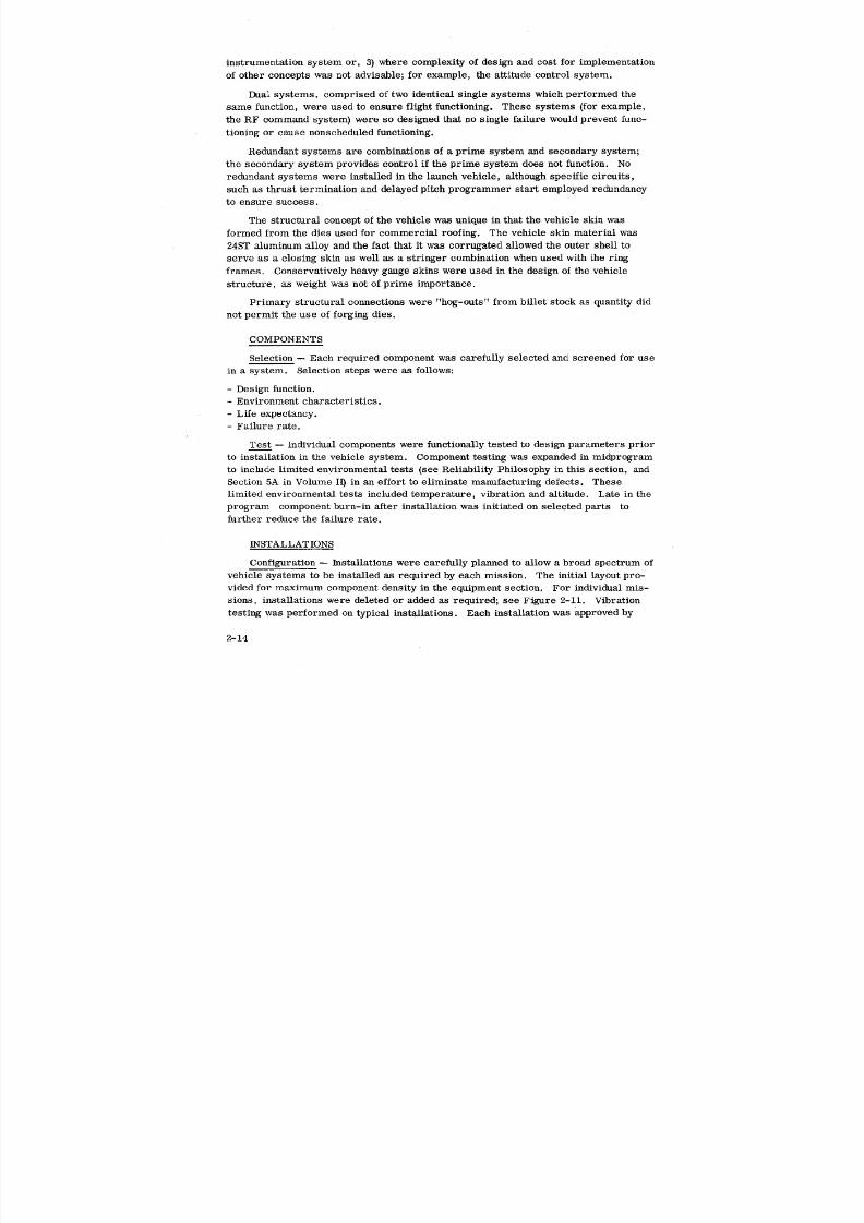
instrumentation system or, 3) where complexity of design and cost for implementation
of other concepts was not advisable; for example, the attitude control system.
Dual Systems, comprised of two identical single systems which performed the
same function, were used to ensure flight functioning. These systems (for example,
the RF command system) were so designed that no single failure would prevent func-
tioning or cause nonscheduled functioning.
Redundant systems are combinations of a prime system and secondary system;
the secondary system provides control if the prime system does not function. No
redundant systems were installed in the launch vehicle, although specific circuits,
such as thrust termination and delayed pitch programmer start employed redundancy
to ensure success.
The structural concept of the vehicle was unique in that the vehicle skin was
formed from the dies used for commercial roofing. The vehicle skin material was
24ST aluminum alloy and the fact that it was corrugated allowed the outer shell to
serve as a closing skin as well as a stringer combination when used with the ringframes. Conservatively heavy gauge skins were used in the design of the vehicle
structure, as weight was not of prime importance.
Primary structural connections were "hog-outs" from billet stock as quantity did
not permit the use of forging dies.
COMPONENTS
Selection -- Each required component was carefully selected and screened for use
in a system. Selection steps were as follows:
- Design function.- Environment characteristics.
- Life expectancy.
- Failure rate.
Test -- Individual components were functionally tested to design parameters prior
to installation in the vehicle system. Component testing was expanded in midprogram
to include limited environmental tests (see Reliability Philosophy in this section, and
Section 5A in Volume I1) in an effort to eliminate manufacturing defects. These
limited environmental tests included temperature, vibration and altitude. Late in the
program component burn-in after installation was initiated on selected parts to
further reduce the failure rate.
INSTALLATIONS
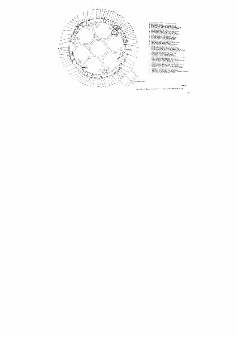
Configuration -- Installations were carefully planned to allow a broad spectrum of
vehicle systems to be installed as required by each mission. The initial layout pro-
vided for maximum component density in the equipment section. For individual mis-
sions, installations were deleted or added as required; see Figure 2-11. Vibration
testing was performed on typical installations. Each installation was approved by
2-14
8/6/2019 Little Joe II Test Launch Vehicle NASA Project Apollo. Volume 1 Management
http://slidepdf.com/reader/full/little-joe-ii-test-launch-vehicle-nasa-project-apollo-volume-1-management 43/157
34 FINIII9 55
9
I0 291817
12 4030
38 537
28 41
_6
1 SUPPORT HOOKS (REF)
41 .59 2 BATTERY INSTALLATICN-RF COMMAND SYSTEM
23 3 ANTENNA I_ISTALLATICN- RF COMMAND SYSTEM
4 RECEIVERINSTALLATION - RFCOMMANDSYSTEM5 COUPLERINSTALLATION- ANTENNARF COMMANDSYSTEM6 SAFEANDARM INSTALLATION - RF COMMANDSYSTEM7 BOX INSTALLATION- RELAYABORTAND DESTRUCT
8 POWERCHANGEOVERSWITCH INSTALLATION - VEHICLE9 BATTERY INSTALLATICN- VEHICLE ELECTRICAL10 DIODE INSTALLATION- VEHICLE, ATTITUDE CONTROL
32 II TERMINAL ,BOARDINSTALLATION- VEHICLE, ELECTRICAL
51 - 12 COVER INSTALLATION - VEHICLE UMBILICAL2 13 TERMINAL BOARD INSTALLATION -RF COMMAND SYSTEM
3c 14 RATEGYROINSTALLATION - ATTITUDE CONTROL15 INVERTERINSTALLATION - ATTITUDE CONTROL
2 16 GYROINSTALLATION - ATTITUDE CONTROL
17 TIMER INSTALLATION - IGNITICN, ATTITUDE CONTROL1B BOXINSTALLATION - IGNITION CONTROL
7 19 CONTROLUNITINSTALLATION - ATTITUDE CONTROL
20 BOX I NSTALLATION- RELAY, GYROCONTROL
FIN IV 0 0 FIN II 21 BOXINSTALLATION - PITCH-UPATTITUDE CONTROL22 FILTER INSTALLATION - ATTITUDE CONTROL SYSTEM
11 25 BOXINSTALLATICN - RELAYPITCH PROGRAMMERCCNTROL
15 41 24 SIGNAL CONDITIONINGBOX INSTALLATION - INSTRUMENT SYSTEM25 SENSORANDRELAYBOXINSTALLATION - ELECTRICAL
27-- 26 CONTROLBOXINSTALLATION - TIMER, IGNITION27 RELAY INSTALLATION- INVERTERCONTROL
28 SHUNTINSTALLATION- BATTERY, ELECTRICAL
28 29 RECEPTACLEINSTALLATION - SHORTING, IGNITION30 PITCHPROGRAMMERNSTALLATION - ATTITUDE CONTROLSYSTEM
3 31 BOXINSTALLATICN- AMPLIFIER INSTRUMENT SYSTEM
32 BOX INSTALLATION- RELAY, BATTERY, RF COMMAND SYSTEM
33 TELEMETRYINSTALLATION- VEHICLE, RF-1O 54 ANTENNA INSTALLATICN -WSMRDESTRUCT SYSTEM
10 35 COUPLER INSTALLATION - ANTENNA, WSMR DESTRUCT SYSTEM1 56 MODULE INSTALLATICN-WSMR DESTRUCTSYSTEM
37 LANYARDINSTALLATION- SANDA , WSMRDESTRUCT SYSTEM22 38 COUPLER INSTALLATICN - ANTENNA T/M, ATTITUDE CONTROL
39 ANTENNAINS_ALLATICN - T/M, ATTllUDE CONTROL
6 _., 40 TRANSDUCEPINSTALLATION - PITCHpHI:CRAMMER
"5/" _ 41 ACCELERCMETER INSTALLATION- INSTRUMENT UPPERANDLOWERBODY
34 /-- X 42 RELAY INSTALLATION - INSTRUMENT SYSTEM
8
14/."
4 13 FIN I 18 17 29 9 -( c-_eoz-22v
Fi&,ure 2-11. Equipment Installation Layout (Vehicle Station 34.75)
2-15
8/6/2019 Little Joe II Test Launch Vehicle NASA Project Apollo. Volume 1 Management
http://slidepdf.com/reader/full/little-joe-ii-test-launch-vehicle-nasa-project-apollo-volume-1-management 44/157
Dynamics as well as stress personnel to ensure an adequate environmental design
margin.
Control Assemblies -- Standard welded boxes were fabricated for control assem-
blies. The boxes matched structural corrugations when mounted vertically or hori-
zontally. Redundant relays in any given assembly were oriented normal to one another
to minimize failures due to common vibration modes.
Support Equipment -- Ground support equipment and facility were designed to
accommodate system changes and additions. Facility junction boxes were provided
initially with 25% spare capability. Provisions were made in consoles and equipment
racks for added circuit distribution. Nearly all GSE was portable to enable use at
several sites. Support Equipment costs were significantly reduced by the use of
blanket specifications for given classes of equipment; refer to Volume H, Major GSE,
for details.
D. LAUNCH OPERAT_NS
In Convair's experience, Launch Operations has proven to demand crew adaptabil-
ity, versatility and quick response to the pressures occasioned by prelaunch and count-
down procedures. With this background Convair organized their off-site operations in
a pattern capable of responding rapidly and efficiently to last minute changes. Flexi-
bility and versatility were the governing factors in establishing the operational pro-
cedures and in selecting personnel.
Original planning was based on the schedule in the RFP. It was anticipated that
the field assembly and checkout of a vehicle would require approximately one month
and that launching would be at the close intervals indicated; therefore the launch oper-
ations crew would be used for vehicle factory checkout, thereby eliminating dual crews
and dual learning curves. This procedure permitted the earliest possible crew famil-
iarization with the vehicle and benefited the program by allowing quick response to field
type changes.
The launcher installation was the first scheduled task at WSMR. Since this one-
time task overlapped the factory checkout of the first vehicle, a special team com-
prised of personnel involved in the trial launcher assembly at the factory was used so
as not to interrupt the launch vehicle team.
The resident off-site staff was initially organized as primarily an administrative
and material group to support the temporary crews. As the program developed, theamount of test site work between lannchings increased, primarily due to configuration
changes and added tasks. As this was recognized, the support and quality control
supervisors, along with a small crew, were established as resident employees at
WSMR. Later, two engineers were added to this crew. During the last year, a
resident crew of 25 was used for administration, material and quality control, facility
refurbishment, modification and telemetry station operation and maintenance.
2-17
8/6/2019 Little Joe II Test Launch Vehicle NASA Project Apollo. Volume 1 Management
http://slidepdf.com/reader/full/little-joe-ii-test-launch-vehicle-nasa-project-apollo-volume-1-management 45/157
Early in the program considerable differences existed between factory and field
checkout procedures, due primarily to the significant differences in the configuration
of the factory and field test facilities. This meant that field operations were under-
taken with essentially "unproofed" procedures. An excessive amount of procedure re-
vision had to be accomplished in the field - a significant unplanned task and a threat to
work schedules. Starting with the third launch vehicle, relief from this situation waseffected by modification of the factory test facility with respect to configuration of
wiring, test consoles_ power supplies, recorders, etc., to closely simulate the WSMR
facilities. Additionally, the Apollo Procedure standard format was adopted for pro-
cedure preparation. Concurrently, NASA introduced the Predelivery Acceptance
Testing (PAT) plan, which called for realistic trial conduction and proofing, at the
factory, of the field procedures (less those involving the payload, ordnance, and the
RCS}. This resulted in a significant improvement in future checkout operations in the
field.
Generally, the Launch Operations philosophy established at the start of the program
remained valid. It was sufficiently flexible to cope with schedule changes and the ex-
tended test operations period. The unforeseen task of considerable facility maintenance
and modification between launchings and the requirement for more comprehensive
component testing was accommodated. The methods of operation readily accepted new
tasks such as the Control System Test Facility (CSTF) operation and the manning of
the NASA telemetry station.
In all aspects of this work, close coordination was maintained with NASA Field
Operations personnel, and through them with the other program contractors and the
test range organization.
E. TOOLING
The tooling philosophy covering the general tool design and tooling manufacturing
policy was based on limited production requirements (maximum of 14 vehicles} and
rapid incorporation of engineering changes. The planning and tooling approach was
guided by achievement of production schedules through minimum planning and tooling;
it made use of worker skills rather than depending on a completely tooled production
program. The basic objectives of producibility and value control were implemented
by tooling functions to assure practical and economical product manufacture.
Detail fabrication of sheet metal and machine parts was accomplished with stan-
dard equipment and standard tools in most instances. Mandatory tools were furnished
as necessary for forming operations. Machine parts in the fin attachment areas were
adequately tooled to make fin attach points interchangeable. Subassembly tools were
provided where dictated by complexity and tolerance requirements (spars, frames
and bulkheads), and were fabricated in the most economical method; see Figure 2-12.
.Assembly tools provided means for positioning and clamping. The fin assembly fix-
ture, built in the vertical position, was used for positioning pre-assembled spars,
2-18
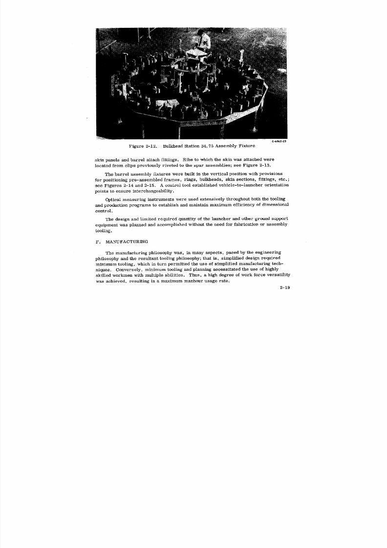
8/6/2019 Little Joe II Test Launch Vehicle NASA Project Apollo. Volume 1 Management
http://slidepdf.com/reader/full/little-joe-ii-test-launch-vehicle-nasa-project-apollo-volume-1-management 46/157
C,-bOb2-23
Figure 2-12. Bulkhead Station 34.75 Assembly Fixture
skin panels and barrel attach fittings. Ribs to which the skin was attached were
located from clips previously riveted to the spar assemblies; see Figure 2-13.
The barrel assembly fixtures were built in the vertical position with provisionsfor positioning pre-assembled frames, rings, bulkheads, skin sections, fittings, etc. ;
see Figures 2-14 and 2-15. A control tool established vehicle-to-launcher orientation
points to ensure interchangeability.
Optical measuring instruments were used extensively throughout both the tooling
and production programs to establish and maintain maximum efficiency of dimensional
control.
The design and limited required quantity of the launcher and other ground support
equipment was planned and accomplished without the need for fabrication or assembly
tooling.
F. MANUFACTURING
The manufacturing philosophy was, in many aspects, paced by the engineering
philosophy and the resultant tooling philosophy; that is, simplified design required
minimum tooling, which in turn permitted the use of simplified manufacturing tech-
niques. Conversely, minimum tooling and planning necessitated the use of highly
skilled workmen with multiple abilities. Thus, a high degree of work force versatility
was achieved, resulting in a maximum manhour usage rate.
2-19
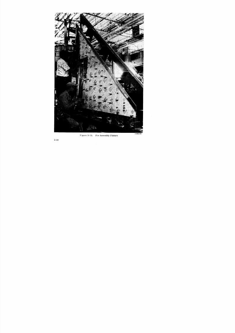
8/6/2019 Little Joe II Test Launch Vehicle NASA Project Apollo. Volume 1 Management
http://slidepdf.com/reader/full/little-joe-ii-test-launch-vehicle-nasa-project-apollo-volume-1-management 47/157
I 0

8/6/2019 Little Joe II Test Launch Vehicle NASA Project Apollo. Volume 1 Management
http://slidepdf.com/reader/full/little-joe-ii-test-launch-vehicle-nasa-project-apollo-volume-1-management 48/157
Cjo062-25
Figure 2-14. Assembling Afterbody Fixture After Loading With Parts
2-21

8/6/2019 Little Joe II Test Launch Vehicle NASA Project Apollo. Volume 1 Management
http://slidepdf.com/reader/full/little-joe-ii-test-launch-vehicle-nasa-project-apollo-volume-1-management 49/157
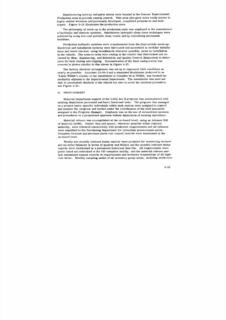
8/6/2019 Little Joe II Test Launch Vehicle NASA Project Apollo. Volume 1 Management
http://slidepdf.com/reader/full/little-joe-ii-test-launch-vehicle-nasa-project-apollo-volume-1-management 50/157
Manufacturing activity and parts stores were located in the Convair Experimental
Production area to provide central control. This area also gave more ready access to
highly skilled workmen and previously developed, simplified procedures and tech-
niques. Figure 2-16 illustrates the production area.
The philosophy of mock-up in the production units was employed in the manufacture
of hydraulic and electric systems. Satisfactory hydraulic clean room techniques wereachieved by using low-cost portable clean rooms and by remodeling permanent
facilities.
Production hydraulic systems were manufactured from the first-article mock-up.
Electrical and installation systems were fabricated and assembled in modular installa-
tions and bench checked, using breadboards wherever possible, prior to installation
in the vehicle. The area-to-area wire routing in the vehicle was determined and re-
viewed by Shop, Engineering, and Reliability and Quality Control (Inspection} to deter-
mine the best routing and clipping. Documentation of the final configuration was
covered in photos similar to that shown in Figure 2-17.
The factory checkout arrangement was set up to represent field conditions as
nearly as possible. Launcher 12-60-2 and a simulated blockhouse (referred to as
"Little WSMR") similar to the installation at Complex 36 at WSMR, was located im-
mediately adjacent to the Experimental Department. The installation was used not
only to accomplish checkout of the vehicle but also to proof the checkout procedure;
see Figure 2-18.
G. PROCUREMENT
Material Department support of the Little Joe II program was accomplished with
existing department personnel and basic functional units. The program was managed
on a project basis; specific individuals within each section were assigned to control
and monitor the program and worked under the coordination of the staff specialist
assigned to the Program Manager. Emphasis was on the use of streamlined systems
and procedures in a projectized approach without duplication of existing operations.
Material release was accomplished at the on-board level, using an Advance Bill
of Material (ABM). Vendor data and spares, wherever possible within contract
authority, were released concurrently with production requirements and all releases
were expedited to the Purchasing Department for immediate procurement action.
Complete forecast and purchase parts cost control records were maintained at the
on-board level.
Weekly and monthly contract status reports were produced for monitoring on-hand
and on-order balances in terms of quantity and dollars and the monthly contract status
reports were maintained as a permanent historical data file. All requirements were
parts listed and submitted to the 705 computer facility, and the material release ana-
lyst maintained manual records of requirements and inventory transactions of all high-
cost items. Monthly sampling audits of all inventory group areas, including stockroom
2-23
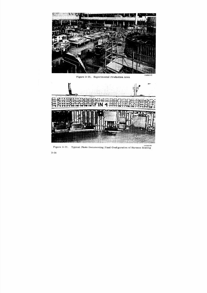
8/6/2019 Little Joe II Test Launch Vehicle NASA Project Apollo. Volume 1 Management
http://slidepdf.com/reader/full/little-joe-ii-test-launch-vehicle-nasa-project-apollo-volume-1-management 51/157
C-6062-27
Figure 2-16. Experimental Production Area
C-6062-28
Figure 2-17. Typical Photo Documenting Final Configuration of Harness Routing
2-24
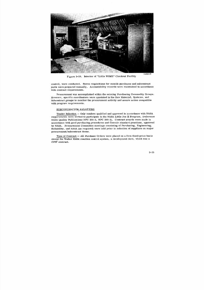
8/6/2019 Little Joe II Test Launch Vehicle NASA Project Apollo. Volume 1 Management
http://slidepdf.com/reader/full/little-joe-ii-test-launch-vehicle-nasa-project-apollo-volume-1-management 52/157
C-6062-29
Figure 2-18. Interior of "Little WSMR" Checkout Facility
control, were conducted. Stores requisitions for outside purchases and subcontract
parts were prepared manually. Aecountability records were maintained in accordance
with contract requirements.
Procurement was accomplished within the existing Purchasing Commodity Groups.
However, specific coordinators were appointed in the Raw Material, Systems, and
Subcontract groups to monitor the procurement activity and assure action compatible
with program requirements.
SUBCONTRACTOR RELATIONS
Vendor Selection -- Only vendors qualified and approved in accordance with NASA
requirements were invited to participate in the NASA Little Joe II Program, (reference
NASA Quality Publications NPC 200-2, NPC 200-3). Contract awards were made in
accordance with good purchasing procedures and Convair standard practices, approvedby NASA. Procurement Committee meetings consisting of Purchasing, Engineering,
Reliability, and NASA (as required) were held prior to selection of suppliers on major
procurement/subcontract items.
Type of Contract -- All Purchase Orders were placed on a firm fixed-price basis
except the Walter Kidde reaction control system, a development item, which was a
CPIF contract.
2-25
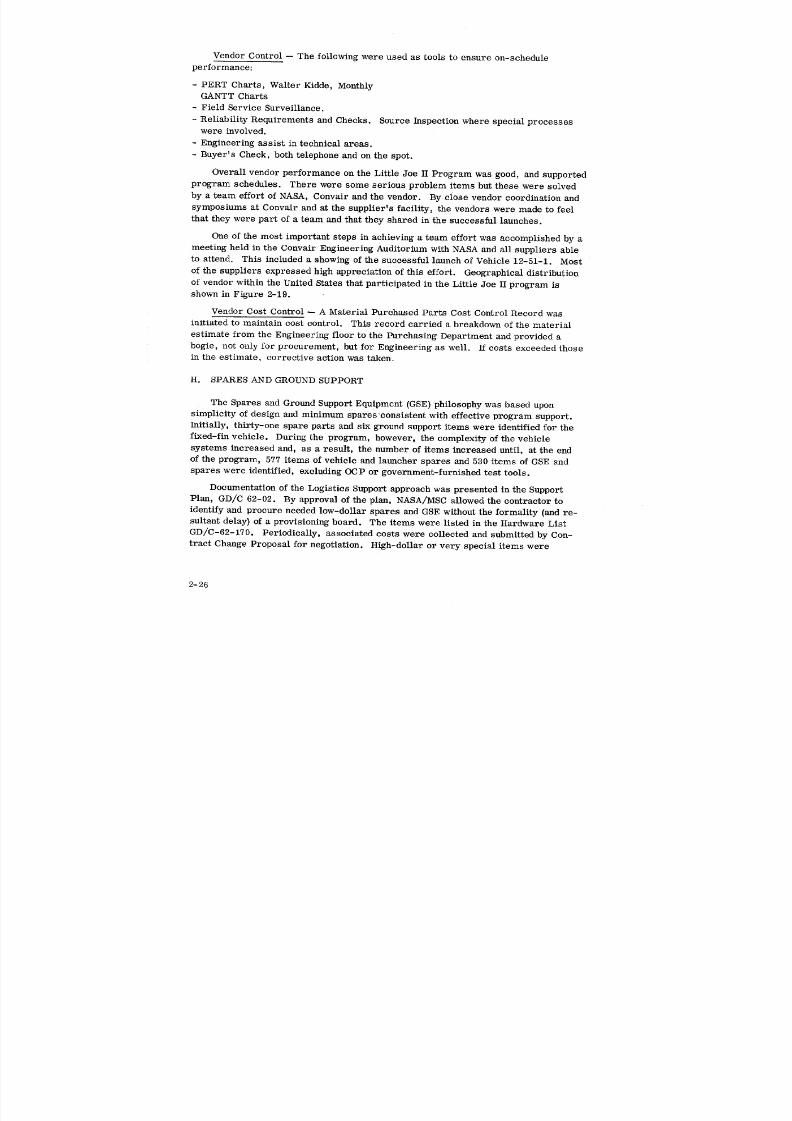
8/6/2019 Little Joe II Test Launch Vehicle NASA Project Apollo. Volume 1 Management
http://slidepdf.com/reader/full/little-joe-ii-test-launch-vehicle-nasa-project-apollo-volume-1-management 53/157
Vendor Control -- The following were used as tools to ensure on-schedule
performance:
- PERT Charts, Walter Kidde, Monthly
GANTT Charts
- Field Service Surveillance.
- Reliability Requirements and Checks. Source Inspection where special processeswere involved.
- Engineering assist in technical areas.
- Buyer's Check, both telephone and on the spot.
Overall vendor performance on the Little Joe II Program was good, and supported
program schedules. There were some serious problem items but these were solved
by a team effort of NASA, Convair and the vendor. By close vendor coordination and
symposiums at Convair and at the supplier's facility, the vendors were made to feel
that they were part of a team and that they shared in the successful launches.
One of the most important steps in achieving a team effort was accomplished by ameeting held in the Convair Engineering Auditorium with NASA and all suppliers able
to attend. This included a showing of the successful launch of Vehicle 12-51-1. Most
of the suppliers expressed high appreciation of this effort. Geographical distribution
of vendor within the United States that participated in the Little Joe II program is
shown in Figure 2-19.
Vendor Cost Control -- A Material Purchased Parts Cost Control Record was
initiated to maintain cost control. This record carried a breakdown of the material
estimate from the Engineering floor to the Purchasing Department and provided a
bogie, not only for procurement, but for Engineering as well. If costs exceeded those
in the estimate, corrective action was taken.
H. SPARES AND GROUND SUPPORT
The Spares and Ground Support Equipment (GSE) philosophy was based upon
simplicity of design and minimum spares consistent with effective program support.
Initially, thirty-one spare parts and six ground support items were identified for the
fixed-fin vehicle. During the program, however, the complexity of the vehicle
systems increased and, as a result, the number of items increased until, at the end
of the program, 577 items of vehicle and launcher spares and 530 items of GSE and
spares were identified, excluding OCP or government-furnished test tools.
Documentation of the Logistics Support approach was presented in the Support
Plan, GD/C 62-02. By approval of the plan, NASA/MSC allowed the contractor to
identify and procure needed low-dollar spares and GSE without the formality (and re-
sultant delay) of a provisioning board. The items were listed in the Hardware List
GD/C-62-170. Periodically, associated costs were collected and submitted by Con-
tract Change Proposal for negotiation. High-dollar or very special items were
2-26
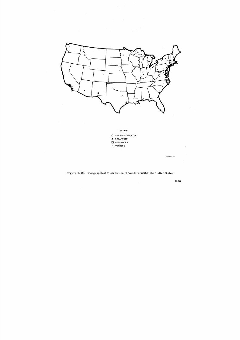
8/6/2019 Little Joe II Test Launch Vehicle NASA Project Apollo. Volume 1 Management
http://slidepdf.com/reader/full/little-joe-ii-test-launch-vehicle-nasa-project-apollo-volume-1-management 54/157
LEGEND
NASA/MSC HOUSTON
NASA/WSTF
[] GD/CONVAIR
• VENDORS
C-6062-30
Figure 2-19. Geographical Distribution of Vendors Within the United States
2-27
8/6/2019 Little Joe II Test Launch Vehicle NASA Project Apollo. Volume 1 Management
http://slidepdf.com/reader/full/little-joe-ii-test-launch-vehicle-nasa-project-apollo-volume-1-management 55/157
discussed with NASA and agreement for use obtained before procurement or design
action was initiated. Status of needed support material was reported in the Hardware
Utilization List, which was developed prior to each scheduled launch.
Because of the increase in the number of required parts, several areas required
special effort to assure adequate, timely support. For both price and schedule con-siderations, all requirements (test, production, spares} were ordered concurrently.
Deliveries for significant or costly components were timed to ensure support of the
factory assembly/checkout operations as well as test site usage.
In addition to the normal spare parts and GSE was the sizable number of required
small parts - bulk items and consumable materials. Because individually each was
inexpensive, and normal methods of ordering and documenting would have been dis-
proportionate to item costs, the initial site quantities were determined and procured.
Adjustments and additions were made as necessary during the program.
NASA required preparation of aPerformance and Interface Specification and an
acceptance document such as an Operational Checkout Procedure for each item of GSE.
It was soon realized that the cost of the associated nonrecurring documentation fre-
quently exceeded the actual cost of the single article needed. As a result, different
identification and procurement procedures were used for off-the-shelf items, low cost
articles and tools supporting system checkouts. Commercially available units were
ordered only after efforts had been made to obtain them from NASA. Many of the low-
dollar checkout tools were developed from simple sketches using materials already
available. Other, somewhat more complicated nonstandard GSE portable test equip-
ment was covered under a blanket interface and performance specification. In addition
to the range of items furnished for the field, a few unique items were also manufactured
for factory use in vehicle handling and checkout.
I. PROGRAM CONTROL
Strong program control was recognized as essential to meet the program schedule
and cost requirements. This involved long range planning as well as detail follow-up
of drawings, changes, procurement and subcontract, interface requirements and task
accomplishment; see Figure 2-20.
Milestone charts (Figure 3-1 in Section 3) were established and maintained in
accordance with contractual and interface requirements and were the basis for overall
long range planning.
PERT networks were developed at a level suitable for monitoring the major pro-
gram milestones and integration of tasks within Convair and NAA in accordance with
the NASA PERT Handbook. The PERT system was supplemented by a Convair-
developed task control technique known as PRESTO (Program Review and Statusing
Operation), which provided timely schedule control at a detail design level for all de-
partments involved. This system generated computer tab listings for monitoring the
"footstones" and was directly oriented with the PERT milestones. During the
2-28
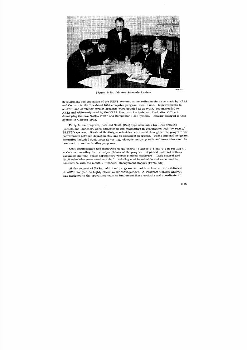
8/6/2019 Little Joe II Test Launch Vehicle NASA Project Apollo. Volume 1 Management
http://slidepdf.com/reader/full/little-joe-ii-test-launch-vehicle-nasa-project-apollo-volume-1-management 56/157
C.-b002=31
Figure 2-20. Master Schedule Review
development and operation of the PERT system, some refinements were made by NASA
and Convair to the Lockheed 7090 computer program then in use. Improvements to
network and computer format concepts were proofed at Convair, recommended to
NASA and ultimately used by the NASA Program Analysis and Evaluation Office in
developing the new NASA/PERT and Companion Cost System. Convair changed to this
system in October 1963.
Early in the program, detailed Gantt (Bar) type schedules for first articles
(vehicle and launcher) were established and maintained in conjunction with the PERT/
PRESTO system. Standard Gantt-type schedules were used throughout the program for
coordination between departments, and to document progress. These internal program
schedules included such tasks as testing, changes and proposals and were also used for
cost control and estimating purposes.
Cost accumulation and manpower usage charts (Figures 4-1 and 4-2 in Section 4),maintained monthly for the major phases of the program, depicted material dollars
expended and man-hours expenditure versus planned manhours. Task control and
Gantt schedules were used as aids for relating cost to schedule and were used in
conjunction with the monthly Financial Management Report (Form 533).
At the request of NASA, additional program control functions were established
at WSMR and proved highly effective for management. A Program Control Analyst
was assigned to the operations team to implement these controls and coordinate all
2-29

8/6/2019 Little Joe II Test Launch Vehicle NASA Project Apollo. Volume 1 Management
http://slidepdf.com/reader/full/little-joe-ii-test-launch-vehicle-nasa-project-apollo-volume-1-management 57/157
activity with San Diego. These controls were mission-oriented by vehicle and were
accomplished as follows (see Figure 2-21 for examples):
PERT -- The first three missions, Vehicles 12-50-1, 12-50-2, and 12-51-1, were
controlled by PERT networks developed in great detail. PRESTO was not used. The
PERT networks, used as a basis for preparation of Gantt type operations schedules,was discontinued by contract for the final two missions, Vehicle 12-51-2 and 12-51-3.
Operations Schedules -- These schedules depicted on standard calendar format all
tasks to be accomplished for the period between launches. The tasks included facility
refurbishment, modification and checkout, and vehicle buildup, checkout and launch.
A summary plan was issued to show overall mission milestones, and each phase of
operation was broken down into separate detail schedules. When PERT was discontin-
ued, some of the PERT concepts, specifically constraints, interdependencies and
slack, were used in development of the Gantt schedules.
Weekly Schedules and Daily Work Plans -- During each vehicle operation at WSMR,
detailed schedules showing constraints and slack were issued weekly and encompassed
the next two weeks of operations. These schedules, showing daily tasks, required
NASA approval and took precedence over all other current schedules. A status meet-
ing was held each day with NASA and Convair operations engineers to determine the
operations for the following day. A daily work plan broken into two-hour increments
was issued as a result of these meetings. The weekly schedules were discontinued at
the start of integrated operations with the spacecraft and resumed again prior to next
vehicle delivery.
Management Briefings -- Briefing meetings were held periodically to discuss
schedule status and open action and shortage items with NASA and Convair manage-
ment. For this purpose, 30-inch x 40-inch display charts were maintained and
minutes documented by Program Control.
Weekly review meetings were conducted with the program management staff in
San Diego and periodic meetings were held with NASA at a frequency of approximately
three weeks, to review overall cost and schedule performance. Although formal
minutes for these meetings were not maintained, pertinent action items and manage-
ment direction were documented by Project Memos. WSMR reports, transmitted daily
to San Diego by teletype, served as a PERT update report as well as a general prog-
ress report to management. Weekly reports were also transmitted from WSMR and
were forwarded to NASA/MSC.
Beginning in September 1962, PERT update and analysis reports were submitted
to NASA/MSC by teletype every two weeks. The update reports proved unsatisfactory
due to lengthy preparation, processing and transmittal time; a data transceiver system
installed in October. 1962 provided direct card-to-card transmittal by use of a data-
phone. The data transceiver system substantially reduced overall transmittal and
processing time and eliminated update errors experienced by the manual method.
Convair was the first NASA/Apollo Program contractor to implement this system; see
Figure 2-22.
2-30
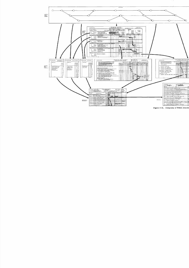
8/6/2019 Little Joe II Test Launch Vehicle NASA Project Apollo. Volume 1 Management
http://slidepdf.com/reader/full/little-joe-ii-test-launch-vehicle-nasa-project-apollo-volume-1-management 58/157

8/6/2019 Little Joe II Test Launch Vehicle NASA Project Apollo. Volume 1 Management
http://slidepdf.com/reader/full/little-joe-ii-test-launch-vehicle-nasa-project-apollo-volume-1-management 59/157
Cjo062-33
Figure 2-22. First PERT Information Transmitted Directly from Convair
to NASA by Telephone
Copies of the PERT networks were maintained and updated at MSC and the result-
ant computer reports were distributed within the NASA management organization.
Identical computer reports were processed at Convair, evaluated by Program Control,
and recommendations were presented to the program management staff.
Change Control -- Change control was employed by Convair to ensure orderly and
expeditious handling of all changes to Engineering design, specifications, and program
plans. Changes were evaluated by the System Integration Staff Member or his dele-
gated alternate to confirm their desirability, necessity, and effect on the program, and
to approve them for further action. A Convair Change Board which met once a week
and was headed by the System Integration Staff Member processed the approved changes
and was responsible for the origin and maintenance of change history records, coordi-
nation of all department activities toward the implementation of changes, and the es-
tablishment of change schedule and cost estimates. It was the responsibility of the
Convair Change Board to report any problems in schedule, cost, etc., to the System
Integration Staff Member for resolution. The Convair Change Board was comprised of
representatives from Engineering, Material, Tooling, Program Control, Manufactur-
ing Control, Factory, Spares, Contract Department, and ProgramManager's Staff, as
required. Every attempt was made to keep Convair-originated changes to a minimum.
Major program changes were approved by NASA, using a Contract Change Authoriza-
tion (CCA).
2-33
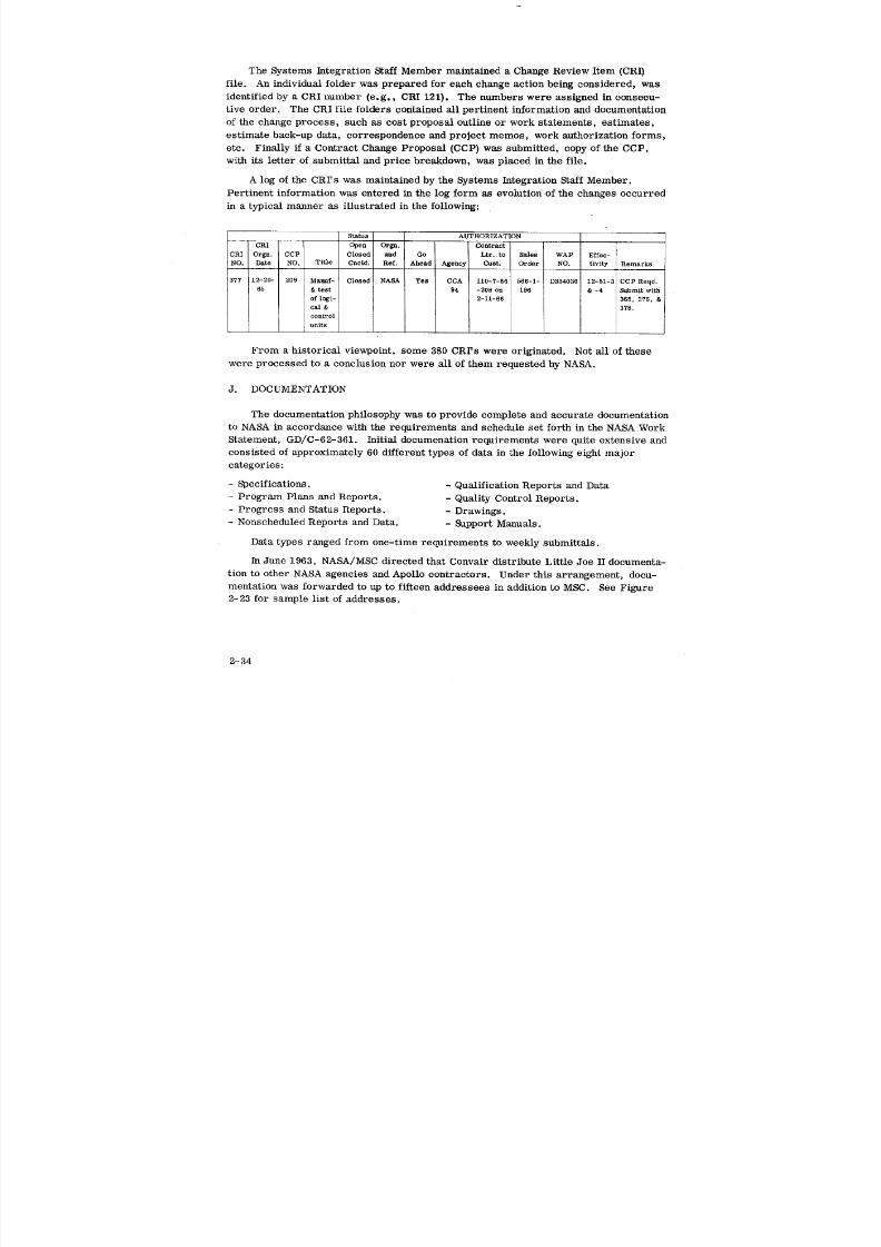
8/6/2019 Little Joe II Test Launch Vehicle NASA Project Apollo. Volume 1 Management
http://slidepdf.com/reader/full/little-joe-ii-test-launch-vehicle-nasa-project-apollo-volume-1-management 60/157
8/6/2019 Little Joe II Test Launch Vehicle NASA Project Apollo. Volume 1 Management
http://slidepdf.com/reader/full/little-joe-ii-test-launch-vehicle-nasa-project-apollo-volume-1-management 61/157
In March 1965, direction was received from NASA significantly reducing extended
distribution of documents and deleting various previously-required documents.
Overall, Convair documentation submittals were 99% within schedule, and the
documentation was considered by NASA to be accurate and complete in content and
format.
Appendix "A" is a list of documentation produced by Convair and its major sub-
contractors during the Little Joe II Program.
K. INTERFACE COORDINATION
Continuing coordination was required to establish compatible system interfaces
during the development and flight operation phases of the project. A procedure was
established to define the framework within which NASA/MSC, North American Aviation,
Inc., - S&ID and Convair could coordinate and document all the interfaces. A similar
procedure was also established for coordinating the interfaces with the contractors forrocket motors - Aerojet-General Corporation and the Thiokol Corporation.
At the beginning of the program it was the MSC's goal to achieve interface coordi-
uaLioa through the use of an Interface Control Document (ICD), which was the instru-
ment by which the physical, functional, operational, and environmental interfaces were
defined. It recorded, by means of formal engineering data, the mutual agreements
between two or more contractors so that compatibility between designs could beestablished.
INTERFACE COORDINATION WITH NORTH AMERICAN AVIATION, INC. , -
SPACE & INFORMATION SYSTEMS DIVISION (NAA S&ID)
Initially, NAA, S&ID was assigned contractual responsibility for interface coordi-
nation. The first interface meetings were concerned with the interchange of technical
data, coordination activities, procedural considerations, and finally, the format of the
document(s) which would delineate interface control procedures. NASA/MSC chaired
the initial meetings, the first of which was held 18 July 1962. During the period of
time between the first meeting and the signing of a Memorandum of Understanding,
coordination was conducted on an informal basis and recorded by Project Memos,
meeting minutes, or suitable letters. After the initial coordination by NASA, inter-
face control was handled almost exclusively by the contractors.
A Memorandum of Understanding signed on 24 June 1963 established the framework
for technical and management coordination between NAA (S&ID) and Convair. This
memo was prepared in accordance with paragraph 5.6 of the Documentation Require-
ments of Contract NAS 9-150. The current issue of the Memo of Understanding, re-
vised 21 February 1964, covers communications, coordination meetings, interface
control, the Preparation Manual (Appendix A) and Detailed Interface Implementing
Instructions (Appendix B).
Appendix B prescribes the communication chain, formal correspondence, informal
exchange of technical information, visits, agenda, minutes of meetings, action items,
2-35

8/6/2019 Little Joe II Test Launch Vehicle NASA Project Apollo. Volume 1 Management
http://slidepdf.com/reader/full/little-joe-ii-test-launch-vehicle-nasa-project-apollo-volume-1-management 62/157
2-36
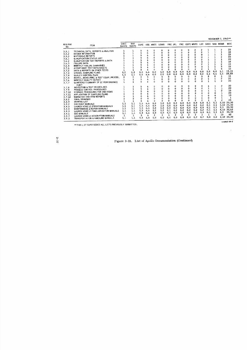
8/6/2019 Little Joe II Test Launch Vehicle NASA Project Apollo. Volume 1 Management
http://slidepdf.com/reader/full/little-joe-ii-test-launch-vehicle-nasa-project-apollo-volume-1-management 63/157
2-37
8/6/2019 Little Joe II Test Launch Vehicle NASA Project Apollo. Volume 1 Management
http://slidepdf.com/reader/full/little-joe-ii-test-launch-vehicle-nasa-project-apollo-volume-1-management 64/157
ICD drawings, changes and authorized signatures. Most importantly, the document
delineates the person-to-person contact for the various engineering disciplines and
points of interface.
Interface coordination with NAA (S&ID} resulted in the completion of four Interface
Control Documents concerning the following missions: 1) Mission A-001, Little Joe IIVehicle 12-50-2 and Payload Boilerplate 12 (BP-12) Document Number MH01-04010-414
dated 17 March 1964, 2) Mission A-002, Little Joe II Vehicle 12-51-1 and BP-23 Docu-
ment Number MH01-04012 dated 6 October 1964, 3) Mission A-003, Little Joe H
Vehicle 12-51-2 and BP-22 Document Number MH01-04Q11-414 dated 30 March 1965,
and 4) Mission A-004, Little Joe H Vehicle 12-51-3 and Spacecraft 002 (SC-002)
Document Number MH01-04013-414 dated 6 August 1965.
Interface coordination required thirty-eight formal meetings in accordance with
the Memorandum of Understanding. Of special importance, items not resolved or
requiring resolution were defined and identified for further action.
INTERFACE COORDINATION WITH AEROJET-GENERAL CORPORATION
In the interface coordination meeting with Aerojet on 24 May 1962, it was agreed
that an interface document should be prepared as soon as possible as a coordinated
effort, with Aerojet having contractual responsibility for the ICD.
A series of biweekly conferences between NASA/MSC, Aerojet and Convair was
planned. The meetings were chaired by MSC and the minutes were the responsibility
of the host contractor. During the course of these meetings, various problems were
resolved relative to the technical material, requirement changes, design changes,
data presentation and funding. Any exchange of technical data outside of the biweekly
meetings was to be made with a simultaneous submittal to NASA/MSC. Interface Con-
trol Document and technical interchange meetings were held more often than biweekly
at the start of the program; however, after the technical aspect of the program and the
vehicle missions became established, the meetings became less frequent.
In July 1963, a copy of Aerojet's Interface Control Document, Report No. 0667-
TICD-1 dated 1 July 1963, was received. Technical meetings and telephone conversa-
tions relative to particular technical problems continued successfully. Later in the
program NASA/MSC asked if Convair could continue without updating the ICD, and
proceed on the basis of Aerojet engineering drawings. Convair agreed that drawingscould be used.
INTERFACE COORDINATION WITH THIOKOL
The initial technical meeting with Thiokol was held at their plant on 9 July 1962.
The basic technical problems relative to the use of Recruit rocket motors in the launch
vehicle, and all aspects of motor performance and installation, were reviewed. In
effect, this meeting started the interface coordination task.
2-38
8/6/2019 Little Joe II Test Launch Vehicle NASA Project Apollo. Volume 1 Management
http://slidepdf.com/reader/full/little-joe-ii-test-launch-vehicle-nasa-project-apollo-volume-1-management 65/157
8/6/2019 Little Joe II Test Launch Vehicle NASA Project Apollo. Volume 1 Management
http://slidepdf.com/reader/full/little-joe-ii-test-launch-vehicle-nasa-project-apollo-volume-1-management 66/157
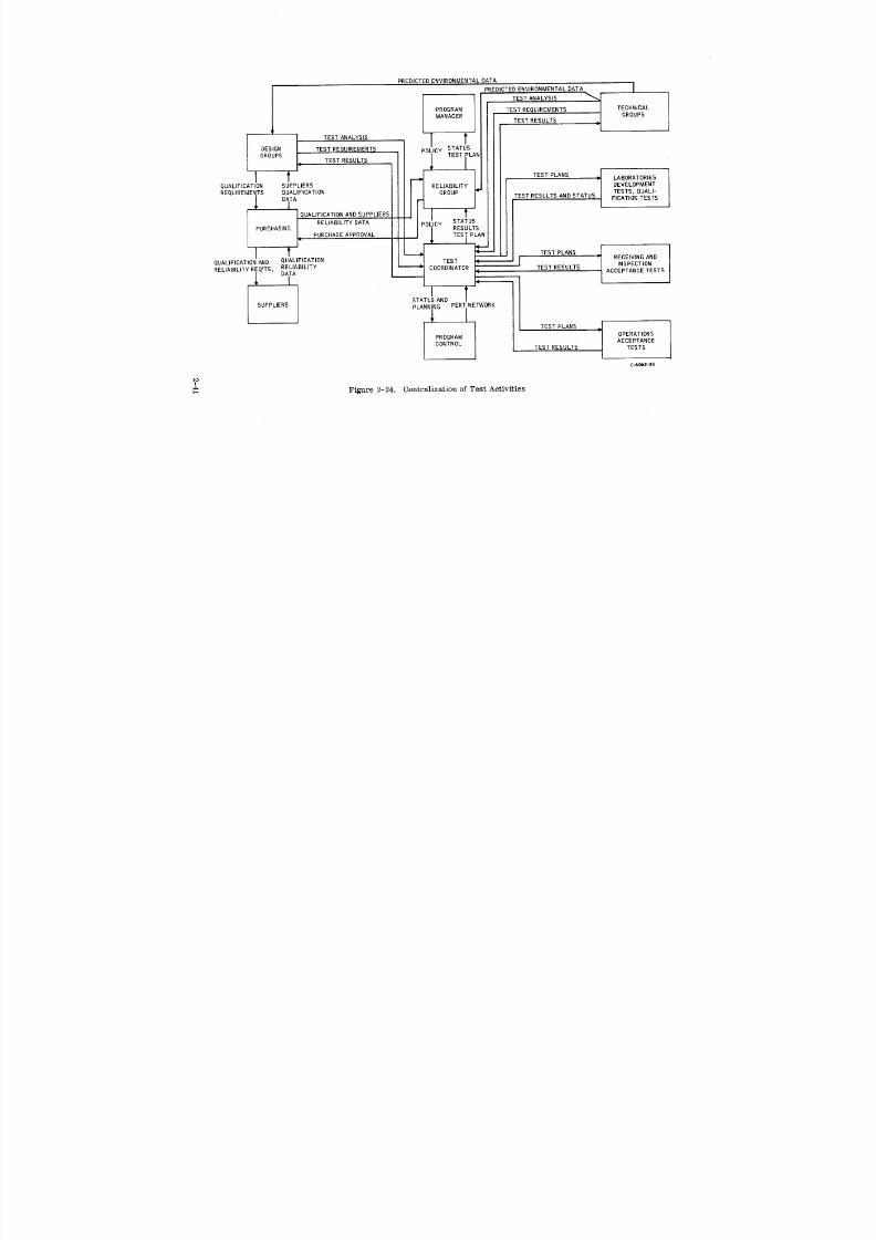
8/6/2019 Little Joe II Test Launch Vehicle NASA Project Apollo. Volume 1 Management
http://slidepdf.com/reader/full/little-joe-ii-test-launch-vehicle-nasa-project-apollo-volume-1-management 67/157
PREDICTED ENVIRONMENTAL DATA
I PREO,CTEONVIRONMENTALATA I
TEST ANALYSIS
PROGRAM TEST REQUIREMENTS TECHNICAL
MANAGER TEST RESULTS _ GROUPS
DESIGN TEST REQUIREMENTS I POLICY STATUSTEST LAN
GROUPS TEST RESULTS
I _ I1_1 ? t TEST PLANS _i LABORATORIES
QUALIFICATION SUPPLIERS RELIABILITY DEVELOPMENT
REQUIREMENTS QUALIFICATION GROUP TEST RESULTS AND STATUS TESTS, QUALI-
DATA FICATION TESTSI
UALIFICATION AND SUPPLIERS IP STATUS
PURCHASING RELIABILITY DATA O_ICY RESULTS
PURCHASE APPROVAL II"I t TESTLANS
TEST -- I ,NSPECT,ONUALIFICATION AND QUALIFICATION
RELIABILITY REQ'TS. RELIABILITY COORDINATOR TEST RESULTSDATA ACCEPTANCE TESTS
i tTATUS AND
SUPPLIERS PLANNING PERT NETWORK
TEST PLANS i
PROGRAM OPERATIONSACCEPTANCE
CONTROL TEST RESULTS TESTS
C-6062-35
I
Figure 2-24. Centralization of Test Activities-a
8/6/2019 Little Joe II Test Launch Vehicle NASA Project Apollo. Volume 1 Management
http://slidepdf.com/reader/full/little-joe-ii-test-launch-vehicle-nasa-project-apollo-volume-1-management 68/157
The amount of testing required for individual components was increased during the
span of the Little Joe II program. Prior to the launch of Vehicle 12-51-1 Convair
initiated an environmental acceptance (Limited Stress) test program on all functional
components. The purpose of this program was to reject marginal parts and thereby
increase confidence in vehicle system reliability. The environments selected included
vibration (one-third qualification level), high temperature and low pressure, depending
upon the type of component being tested. (Refer to Volume II for program results. )
Spare component burn-in was initiated prior to the launch of Vehicle 12-51-3. A
review of failure records indicated that 75% of the components that failed had less than
five hours of operation and 95% had less than 50 hours. The program's purpose was to
ensure that critical components installed in the vehicle had accumulated at least 50
hours of operation. The implementation of this program eliminated components which
would fail after only a few hours of operation.
QUALITY CONTROL
Quality Control traceability activities consisted of a system of serial numbering
and identification, plus controlled stocking which permitted tracing of all significant
material and functional items from receipt through storage, fabrication, assembly and
delivery. Raw material was traceable to the foundry.
The final configuration of each launch vehicle and its conformance to released
engineering drawings was assured through an audit of planning paper against blue-
prints prior to acceptance. Verification of launch vehicle configuration status was a
prerequisite to Predelivery Acceptance Tests.
All articles received were subjected to a thorough receiving inspection. Contrac-
tor source inspection was provided at the vendor's or supplier's facility when receiving
inspection was not feasible.
A narrative end-item report, prepared in accordance with NASA Quality Publica-
tion NPC 200-2 and NASA Statement of Work, GDC-62-361, was submitted for each
end-item delivered under the contract. The first report for each launch vehicle was
furnished to NASA concurrent with vehicle shipment from San Diego; the second report
was furnished at the time of final NASA acceptance, and vehicle launch, at WSMR.
The reports were compiled in narrative form with attachments as necessary, covering
the periods from subassembly installation through final acceptance of each end-item.
Classes were conducted at Convair and at Vendor's facilities, to assure thatemployees were properly prepared to accomplish the assigned task. This training at
Convair was allocated in the following manner:
2-42
8/6/2019 Little Joe II Test Launch Vehicle NASA Project Apollo. Volume 1 Management
http://slidepdf.com/reader/full/little-joe-ii-test-launch-vehicle-nasa-project-apollo-volume-1-management 69/157

8/6/2019 Little Joe II Test Launch Vehicle NASA Project Apollo. Volume 1 Management
http://slidepdf.com/reader/full/little-joe-ii-test-launch-vehicle-nasa-project-apollo-volume-1-management 70/157
3 I SCHEDULE SUMMARY
8/6/2019 Little Joe II Test Launch Vehicle NASA Project Apollo. Volume 1 Management
http://slidepdf.com/reader/full/little-joe-ii-test-launch-vehicle-nasa-project-apollo-volume-1-management 71/157
3 SCHEDULE SUMMARY
A. MILESTONES
The time-sequenced milestones shown An Figure 3-1 reflect major events of the
total program, Sheets 1 and 2 portray completion events for contracts, engineering,
tooling, production, material procurement, GSE, testing and documentation. These
milestones correlate with the events of the PERT Networks and Gantt charts used for
internal schedule control and for biweekly reporting to NASA.
B. CONTRACTUAL SCHEDULE CHANGES
Figure 3-2 shows the evolution of each vehicle's final delivery date. Changes to
the contract through Contract Change Authority (CCA} and/or Contract Change Proposal
(CCP) provided the accession of delivery dates. When a contract change specified only
a launch date, the delivery date was automatically established as sixty days prior to
the launch date.
The chart illustrates NASA/MSC's original plan for a short, low-cost program
versus the program span that eventually developed. The majority of the scheduledates incrementally directed or authorized by NASA/MSC were due to replanning of
the NAA S&ID payload to be flown, or because of changes in MSC test requirements.
In essence, Convair met all of the schedules for which At could be held solely respon-
sible.
The chart also emphasizes that a test program such as Little Joe II wherein the
payload is contracted separately from the booster requires flexible and responsive
planning. This was successfully achieved on this program by: 1) building basic
vehicles early and holding them until payload and test requirements were defined, !
2) emphasis on commonality between vehicles, 3} close coordination between contracto_
andcustomer, and 4) fast response to changes as they were identified. I'
3-1

8/6/2019 Little Joe II Test Launch Vehicle NASA Project Apollo. Volume 1 Management
http://slidepdf.com/reader/full/little-joe-ii-test-launch-vehicle-nasa-project-apollo-volume-1-management 72/157
DVEHICLES 2 LAUNCHERS _ --1962 1963
_:_t_'.olu'_".,,'/8'.g::S i+ot:°,,+_,'cTG0-AHEAO] CONTHACTNAS9-492 • •( • _ DEFINITIVECONTRACT \• •
I I -°+-""EL,VER'ESN'TE NO.'. ++.'+_O.,._;CTAUNCHERGROUNDSIIPPORTEQUIPMENT • I I
I NO 1•++°+ / luL'/ iUBSYSTEMS LAST TR I
FF VEHICLE START 1STREL l REL NO Z I / NO 2 SCHEMtENGINEERNG • • ,_ST l •I MFG COUP I _I ACTUALFEB 64MATERIAL eRA w )ISTOSP / 1STVEH. I •LALLAVAIL I ITOOLNG • I / •'-t--Ol•-"t-O M_. COUP. 2NOVEH,FACTORY START I / / I t IFABRICATION • START / /I I O-IICOMP. I I I IASSEMBLY l I(0 Start I I I I •couP, [NO.2 NO.31NO4MAJORTEMSSEMBLY I I [ / I qPCPll I _ Io"l--OI I el • IOPERATIONALCHECKOUT/FACTORYCOMPLETE [ / I //I I I n9. ; I •N0. 11 eND. 21 INTOSTORAGE SANDIEGO / / I //I I I I I I I I / I
I / / LAST STRUCT. I I I I I I I I / I
LAUNCHER START I I REL.I I I _! I l IENGNEERING • •1ST RELol IO I •LAST ELECT. REL. I I /MATERIAL • 1ST MATL. • •ALL AVAIL. I /FACTORY SURT1 I I I NO2COMPJ
FABRCATON&ASSEMBLY _ / eNG. z COMP 0-41FUNCTORALTEST | / I I I • COUP I I I I O-41
GROUNDSUPPORTEQUIPMENT STAI ///lll/lllll [lENGNEERINO • li:s+ eEL. I I I 1 I • LASTEL./ IMATERIAL l •lSt. MATL. (_,--4NALL AVAIL. /FACTORY / I S#ARTI I I ] I I t I ] I/ IFABRCATiON&ASSEMBLY• l I Am I I I IO_COMP. ] Fm IFUNCTIONAL PROOFINGTEST / 1 I I I I I I I •COMF. I / I
ATTITUDECONTROL I / LASY_YO.Il I' IllBREADBOARD START 1ST eEL ( eEL. I I 1 /
ENGINEERING • _ ZSTMATL, •OiLASTREL. I I I lMATERIAL START [ qwr-ot I ! I _ ALLAVAIL, AUTOPILOTSYS.TOOUNG • / I I I•COmF.I t I I ONDOCKS.D.SUBCONTRACT 1 I I / I / t I I o---_ I IFACTORY START I 1 I _ I i I / I I
FABRCATi6N • I I I •COUP. 1 I / COUP.MAJORITEMASSEMBLY START•I I • COUP, IMAR. '64 I
TESTING STAiT _I I I I I 1°1--IACFVEHICLE LONGLEAD 2VEHICLES STARTr'ABGO-AHEAD AATL, • iN _I_}GSE NO, 3-4•ENGINEERINGMATERIAL START! J|l /TAA.,m_ • IREACT.CONT.SYS. d -•C MP.vv_.._ I • 'SUBCONTRACT MOCKUPAVAtL%•! )N ,10 o,2FACTORY n STJPIT AUTOPILOTSYS,
FABRICATION I qJ START IASSEMBLY n O--_
• IOCUMENTATIONGENERAL ) • •
LAUNCHOPERATIONSBYMISSIONTESTFACILITYOCCUPANCY O' • NO. 1
+CNERCHECNOUT I I
PROPULSIONSYSTEM(GFP] IALGOL N0. 1 • ,ONO. 2
+u+ '
LL SYSTEMSTEST /EVALUATION QTV
FLIGHTREPORT + NO, 1
I
LEGEND
0 SCHEDULE _ RE-SCHEDULE
• ACTUAL ACF ATTITUDECONTROLFIN
0'--"0 LATETOSCHEDULE FF RXED RN
AHEADOF SCHEDULE RCS REACTIONCONTROLSYS
C-6062-36-1
Figure 3-1. Milestone Chart (Sheet 1 of 2)
3-2
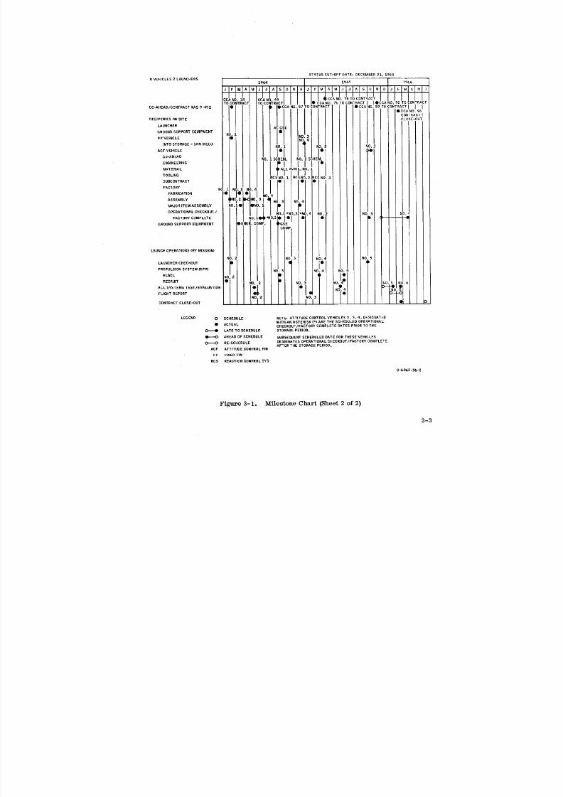
8/6/2019 Little Joe II Test Launch Vehicle NASA Project Apollo. Volume 1 Management
http://slidepdf.com/reader/full/little-joe-ii-test-launch-vehicle-nasa-project-apollo-volume-1-management 73/157
STATUS CUT-OFF DATE: DECEMBER31, 1965
- CCA NO. 18 CCAN _.49 I [ q 0. iTO CONTRACT TO CONTRACT , | • CCANO. 76 TOCONTRACT OCCA NO. 92 TO CONTRACT
GO-AHEAD/CONTRACTNAS 9.-492 • I _ CCA NO, 57 TO CONTRACT • CCANO. 89 TO CONTRACT I I I
_|I eCCAO.6
I CONTRACT IDELIVERIES ONSITE CLOSE-OUT
LAUNCHER IACG_E
GROUNDFFEHIcLESUPPORTQUIPMENT N •)"2! I • NO. 3 t
i I NO, 4INTO STORAGE- SANDIEGO (m_NO. 1 0.3
ACF VEHICLE I'1 / .,O-AHEADNO, 1 SCHEM. NO, 2 SCHEM.
MATERIAL A LAVAI , N .
TOOLING RCSNO. 1 R( LNO.2_RC! NO. 3
SUBCONTRACT I " "'lFACTO N'''''
FABRICATION • NO i
ASSEMBLY ,NIO,2 _0 3 .3 N, .4
MAJOR ITEM ASSEMBLY ,0,.• ,,)=.rill|!PERATIONAL CHECKOUT/ NO.1 *NO.2 *N( . 4 I10o 2 NO. 3 NI
roD.NP*N)'2_11o) " •ACTORYCOMPLETE I C ;GROUNDSUPPORTEQUIPMENT •ENGR. COMP. I •GSE
LAUNCHOPERATIONS (BY MISSION) _ un _ i
; NO.3 ,3.4 N
LAUNCHERCHECKOUT
PROPULSION SYSTEM (GFP) NO 3 NO %!LGOL
RECNUT i _ _O"
ALL SYSTEMS TEST/EVALUATION N 14LIGHT REPORT q
CONTRACTCLOSE-OUT _ _ .... _ -- D_
LEGEND 0 SCHEDULE NOTE: ATTITUDE CONTROLVEHICLES 2, 3, 4, DESIGNATEDWITH ANASTERISK (*) ARE THE SCHEDULEDOPERATIONAL
• ACTUAL CHECKOUT/FACTORY COMPLETE DATES PRIORTO THE
LATE TO SCHEDULE STORAGEPERIOD.
AHEADO FSCHEDULE SUBSEQUENTSCHEDULEDDATE FORTHESE VEHICLES
0_0 RE-SCHEDULE DESIGNATESOPERATIONALCHECKOUT/FACTORY COMPLETEAFTER THE STORAGEPERIOD.
ACF ATTITUDE CONTROL FIN
FF FIXED FIN
RCS REACTION CONTROLSYS
C-6062 -36-2
Figure 3-1. Milestone Chart (Sheet 2 of 2)
3-3
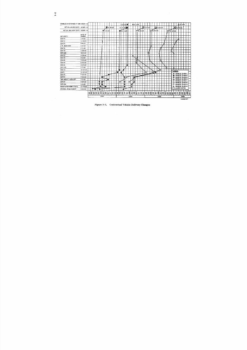
8/6/2019 Little Joe II Test Launch Vehicle NASA Project Apollo. Volume 1 Management
http://slidepdf.com/reader/full/little-joe-ii-test-launch-vehicle-nasa-project-apollo-volume-1-management 74/157
I
Figure 3-2. Contractual Vehicle Delivery Changes

8/6/2019 Little Joe II Test Launch Vehicle NASA Project Apollo. Volume 1 Management
http://slidepdf.com/reader/full/little-joe-ii-test-launch-vehicle-nasa-project-apollo-volume-1-management 75/157
4 FINANCIAL SUMMARY
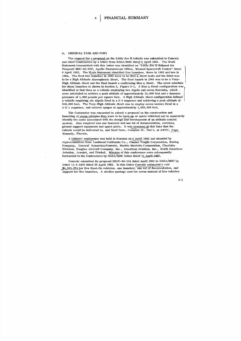
8/6/2019 Little Joe II Test Launch Vehicle NASA Project Apollo. Volume 1 Management
http://slidepdf.com/reader/full/little-joe-ii-test-launch-vehicle-nasa-project-apollo-volume-1-management 76/157
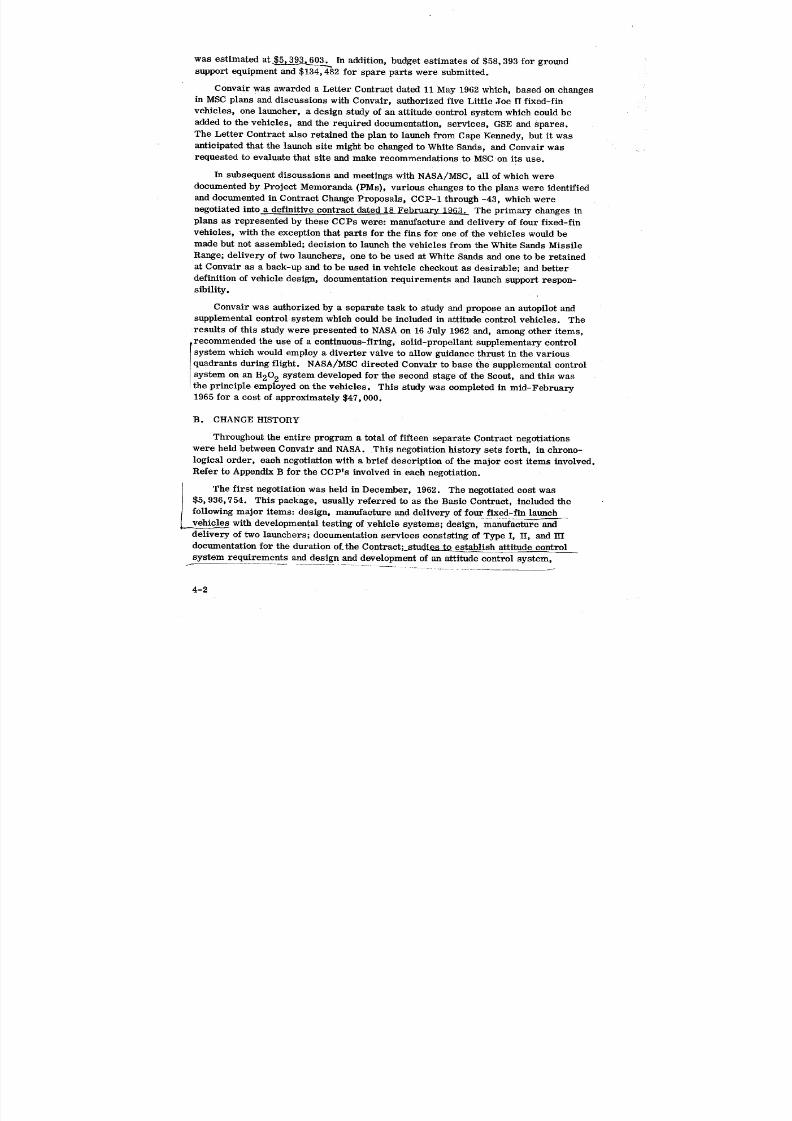
8/6/2019 Little Joe II Test Launch Vehicle NASA Project Apollo. Volume 1 Management
http://slidepdf.com/reader/full/little-joe-ii-test-launch-vehicle-nasa-project-apollo-volume-1-management 77/157
was estimated at_ In addition, budget estimates of $58,393 for groundsupport equipment and $134,482 for spare parts were submitted.
Convair was awarded a Letter Contract dated 11 May 1962 which, based on changes
in MSC plans and discussions with Convair, authorized five Little Joe II fixed-fin
vehicles, one launcher, a design study of an attitude control system which could be
added to the vehicles, and the required documentation, services, GSE and spares.
The Letter Contract also retained the plan to launch from Cape Kennedy, but it was
anticipated that the launch site might be changed to White Sands, and Convair was
requested to evaluate that site and make recommendations to MSC on its use.
In subsequent discussions and meetings with NASA/MSC, all of which were
documented by Project Memoranda (PMs), various changes to the plans were identified
and documented in Contract Change Proposals, CCP-1 through -43, which were
negotiated into a definitive contract dated 18 February 19_3. The primary changes in
plans as represented by these CCPs were: manufacture and delivery of four fixed-fin
vehicles, with the exception that parts for the fins for one of the vehicles would be
made but not assembled; decision to launch the vehicles from the White Sands Missile
Range; delivery of two launchers, one to be used at White Sands and one to be retained
at Convair as a back-up and to be used in vehicle checkout as desirable; and better
definition of vehicle design, documentation requirements and launch support respon-
sibility.
Convair was authorized by a separate task to study and propose an autopilot and
supplemental control system which could be included in attitude control vehicles. The
results of this study were presented to NASA on 16 July 1962 and, among other items,
i recommended the use of a continuous-f|ring, solid-propellant supplementary control
system which would employ a diverter valve to allow guidance thrust in the variousquadrants during flight. NASA/MSC directed Convair to base the supplemental control
system on an H20_ system developed for the second stage of the Scout, and thin was
the principle employed on the vehicles. This study was completed in mid-February
1965 for a cost of approximately $47,000.
B. CHANGE HISTORY
Throughout the entire program a total of fifteen separate Contract negotiations
were held between Convair and NASA. This negotiation history sets forth, in chrono-
logical order, each negotiation with a brief description of the major cost items involved.
Refer to Appendix B for the CCP's involved in each negotiation.
The first negotiation was held in December, 1962. The negotiated cost was
$5, 936,754. This package, usually referred to as the Basic Contract, included the
following major items: design, manufacture and delivery of four fixed-fin launch
vehicles with developmental testing of vehicle systems; design, manufacture and
delivery of two launchers; documentation services consisting of Type I, II, and HI
documentation for the duration of.the Contract; studie_ to establish attitude control
system requirements and design and development of an attitude control system,
4-2
8/6/2019 Little Joe II Test Launch Vehicle NASA Project Apollo. Volume 1 Management
http://slidepdf.com/reader/full/little-joe-ii-test-launch-vehicle-nasa-project-apollo-volume-1-management 78/157
including qualification testing; and off-site services to cover the activation of the test
base facilities and perform tasks necessary to launch four launch vehicles.
The second negotiation was held in April, 1963. The negotiated cost was
$337,456, and covered changes to the existing program to launch a qualification test
vehicle prior to the scheduled Apollo tests. This required acceleration of factory
completion of the four launch vehicles and the two launchers. Launch dates were
moved up for the first two vehicles. An additional telemetry system and an instru-
mentation transmitter system was incorporated in the Qualification Test Vehicle
(12-50-1), which was equipped with a simulated payload consisting of the payload
adapter, command module and a government-furnished _]0ort tower. The launch pad
configuration was redesigned, making necesary the relocation of all rooms and
associated wiring and equipment previously located beneath the launch pad.
The third negotiation was held_3_ The n egotiatefl cost was $2,113,203. _
The major change provided for two additional launch vehicles which incorporated the /_
attitude control subsystem as developed under the basic contract. The additional \vehicles were identified as 12-51-1 and 12-51-2.
The fourth negotiation was held in September, 1963. The negotiated cost was
$354,737. This cost covered study activity and several relatively small changes
requested as a result of the Design Engineering Inspection held on 3 May 1963. In
addition tothe minor changes, provision was made for additional ground support
equipment as a result of the two additional attitude control vehicles. Fabrication of an
additional breadboard autopilot system for use at NASA/MSC was also covered.
Deletion of the dummy payload and limitation of the instrumentation system to the
control system of Vehicle 12-51-1 was covered. This amounted to a substantial credit
to NASA. NAA BP-22 payload was used in lieu of the previously planned dummy pay-load.
The fifth negotiation was held in December, 1963. The negotiated cost was
$468,297. Significant changes included: study and revision of the attitude control sub-
system to comply with a NASA directive to provide closer tolerance on the attitude of
high altitude abort; revision of the instrumentation signal conditioning and calibration
system to change from signal conditioning boards and signal modules to terminal boards
and a signal conditioning box with deletion of certain R and Z calibration functions;
revision of Operational Checkout Instructions (OCI's) to conform with the results of a
NASA review of Convair Operational Checkout Procedures; and incorporation of a
prototype Reaction Control System into the Convair Attitude Control System breadboardtest program.
The sixth negotiation was held in April, 1964. The negotiated cost was $774, 161.
The major changes negotiated were: modification of an existing government-furnished
Project Mercury H202 system service trailer and a stripped H202 trailer to fulfill
H202 servicing requirements of the Little Joe II reaction control system on two
vehicles. Included were fin test stands, and testing and checkout of the reaction
control system and hydraulically-controlled aerodynamic system on each fin;
4-3
8/6/2019 Little Joe II Test Launch Vehicle NASA Project Apollo. Volume 1 Management
http://slidepdf.com/reader/full/little-joe-ii-test-launch-vehicle-nasa-project-apollo-volume-1-management 79/157
additional and revised items of ground support equipment for support of checkout
operations of Vehicle 12-50-2 and on were provided as a result of new H202 require-ments; vibration testing of the reaction control system, instrumentation, and autopilot
systems, and the coverage for Acceptance Data Packages for Vehicles 12-50-1, -2
and -4, Vehicle 12-51-1, and Launcher 12-60-1; and redesign of the umbilical dis-
connect to provide for approximately 100 more wires, added because of system growth.
The seventh negotiation was held in May 1964. Negotiated cost was $1,269, 977.
• 4 The one change involved provided for two additional attitude control launch vehicles
j which were the same as Vehicle 12-51-2 except for deletion of the Walter Kidde
\_ reaction control subsystem. Provisions for installation of the reaction control system
were retained. Task and cost included landline instrumentation, applicable documenta-
tion, GSE, spares and on-site engineering support of Operations Services. Off-site
launch activities were not covered.
The eighth negotiation was held in July, 1964. The negotiation cost was $651, 051.
This costcovered the e
ffect of several s
chedule
chan
ges associated with Vehi
cle
12-50-1, as well as additional quality assurance and program control services at
WSMR, incorporation of a dual-thrust termination system and addition and revision of
ground support equipment for attitude control vehicles.
The ninth negotiation was held in September, 1964. Negotiated cost was $816,043
and included the following: modification of Vehicle 12-51-1 to meet the requirements
of Mission A-002. This involved study and some modification of the attitude control
subsystem due to vehicle mission parameter changes from the original design;
vibration testing of the reaction control system to a 30g level - vibration tests on the
aerodynamic control hydraulic system installed in an attitude control fin and test
fixture were also covered; installation of long-run cables from the launcher to theblockhouse (at WSMR) to accommodate attitude control vehicles; provision of an
attitude control test fin, delivered to Houston together with fin test stand design
drawings, and Convair Engineering assist to NASA/MSC during attitude control fin
system tests conducted there; and addition and revision of ground support equipment
to support the modified vehicle and Mission A-002.
The tenth negotiation was held during October, 1964. Negotiated cost was
$413,081. Two major changes were covered. A minimum crew of Launch Operations
personnel performed test, operations support and other tasks as directed by NASA/
WSMR during and between Little Joe II missions. Convair was also authorized to
provide maintenance and operation of a NASA telemetry trailer at WSMR. The task in
general consisted of setting up, calibrating and operating a government-furnished
ground station to support vehicle pre-launeh test and checkout, and collecting and
recording flight data. Additional coverage included maintenance and repair activities
to maintain, troubleshoot and repair ground station equipment such as recorders,
discriminators, de-commutators, receivers and monitors.
4-4
8/6/2019 Little Joe II Test Launch Vehicle NASA Project Apollo. Volume 1 Management
http://slidepdf.com/reader/full/little-joe-ii-test-launch-vehicle-nasa-project-apollo-volume-1-management 80/157
The eleventh negotiation was held in January, 1965. Negotiated cost was $207,492.
The major changes covered: miscellaneous change incorporation as a result of the
Design Engineering Inspection of Vehicle 12-51-1; provision for a WSMR range safety
system kit and an additional range safety system antenna set for Vehicle 12-51-1; and
design and manufacture of an alternate range safety system kit, together with qualifi-
cation testing of Beckman Whitley destructor, installation of the original range safety
system kit to provide dual capability, and deletion of the existing thrust termination
capability from the RF command system.
The twelfth negotiation was held in March, 1965. The negotiated cost of $600,234
covered the effect of NASA-directed schedule changes on Vehicles 12-50-2, 12-50-3,
12-50-4, 12-51-1, 12-51-2 and 12-51-3, together with modification to the launcher
and the Test Base Facilities to meet the requirements of BP-22 and S/C-002
umbilical installations. In addition, added and revised items of ground support equip-
ment were covered and the maintenance and operation of the NASA telemetry trailer
was extended to 20 June t965.
The thirteenth negotiation was held in June, 1965. Negotiated cost was $2,104,676.
The change cost values negotiated at this session were substantially above the normal
change averages because a large number of tasks were covered in some of the
individual CCP's. The tasks covered: modification of two vehicles (12-51-2 and 12-51-3)
to incorporate design changes which would meet the requirements of respective
Missions A-002 and A-004; modification of the range safety system to cl_ange from a
Yardney battery and a high-energy safe-and-arm unit to a Goulton Battery and a low-
energy safe-and-arm unit. Also, the primacord wrap-around system was deleted
and a series of three firing tests were included, to demonstrate the capability of the
system to provide range destruction of the six-Algol motor configuration; addition and
revision of ground support equipment to support new mission requirements; and in-
corporation of miscellaneous NASA-requested changes to provide additional checkout
procedures on vehicle subsystems. A DEI was conducted on Vehicle 12-51-2 and
several miscellaneous changes resulting therefrom were incorporated. Launch
Operations Services not previously negotiated for support of the five vehicle program
were also covered; for example, the effect on Launch Operations of vehicle configura-
tion changes, rescheduled delivery and launch dates, launcher and facility configuration
changes and the requirements for additional program control and quality assurance at
the test base. Previously negotiated launch operations tasks were subsequently deleted
and credited to NASA.
The fourteenth negotiation was held in September, 1965. Negotiated cost was
$1, 330, 155 and covered the updating of Vehicle 12-51-4 to the Vehicle 12-51-3 con-
figuration. In general this consisted of incorporating changes associated with the
attitude control subsystem such as autopilot gains and adjustments, filters, pitch
programmer, exponential pitch-up system, gyro spin monitor and the additional
hydraulic system capacity installation. The vehicle task included incorporation of
changes associated with the ignition system, dual thrust termination provisions, RF
command with abort and pitch-up capability, range safety system and improved dual
4-5
8/6/2019 Little Joe II Test Launch Vehicle NASA Project Apollo. Volume 1 Management
http://slidepdf.com/reader/full/little-joe-ii-test-launch-vehicle-nasa-project-apollo-volume-1-management 81/157
on-board timers. A hydraulic/GN_ system was added which doubled the previouscapacity and ensured system capability under conditions which might be encountered
on future flights. Design and parts were provided to update the NASA/MSC test fin
and elevon assembly to the same hydraulic system capability. Additional ground
support equipment for support of Vehicles 12-51-2 and on was provided, and mainte-
nance and operation of the NASA telemetry trailer was extended to 31 December 1965.
The fifteenth negotiation to date was held in March 1966. Negotiated cost was
$426,968. Major changes covered were: post-flight investigation and failure analysis
to determine the cause of the in-flight failure of Vehicle 12-51-2, along with investi-
gation and analysis of the attitude control system performance observed during Pre-
delivery Acceptance Testing of Vehicle 12-51-3. Tasks previously negotiated for
Vehicles 12-50-3 and 12-50-4 but not then required were defined, estimated, and
credited to NASA. Convair maintenance and operation of the NASA telemetry trailer
was extended through 31 January 1966. The effect of schedule revisions on Vehicle
12-51-3 was covered, together with failure analysis of the vehicle instrumentation
system and attitude control system components as a result of difficulties experienced.Deletion of previously negotiated tasks on Vehicle 12-51-4 was considered and resulted
in a substantial credit to NASA. Provisions for storage of Vehicle 12-51-4 were also
made.
The sixteenth (final) negotiation was held in May 1966. The negotiated cost of
$103,260 was to provide for additional direct effort peculiar to the contract close-out,
which could not be directly identified to the contractual task as it was originally
constituted. This completed the Little Joe H negotiations.
C. COST ACCUMULATION SUMMARY
The contract value, funding, and expenditure chart shown in (Figure 4-1) displays
requirements and expenditures for the total program. This chart was used by Convair
and NASA/MSC as a control tool to evaluate incremental funding requirements and
dollar expenditure. The chart was updated monthly and issued concurrently with the
Form 533 financial report, which is summarized in Figure 4-5.
D. MANPOWER USAGE SUMMARY
The manpower usage summary chart in Figure 4-2 shows the variation in equiva-
lent direct personnel employed on the program during its life span.
E. MANPOWER USAGE IN 1964
This manpower chart in Figure 4-3 shows a breakdown of equivalent personnel
usage on a weekly increment for Operations Services-WSTF, Reliability, Engineering
including Operations Services-San Diego, Manufacturing, and the total program. This
chart covers a period of one year (1964) and is considered typical for the launching of
two vehicles (12-50-2, fixed-fin, 13 May 1964; and 12-51-1, attitude control, 8 Decem-
ber 1964).
4-6
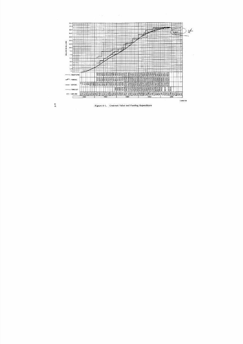
8/6/2019 Little Joe II Test Launch Vehicle NASA Project Apollo. Volume 1 Management
http://slidepdf.com/reader/full/little-joe-ii-test-launch-vehicle-nasa-project-apollo-volume-1-management 82/157
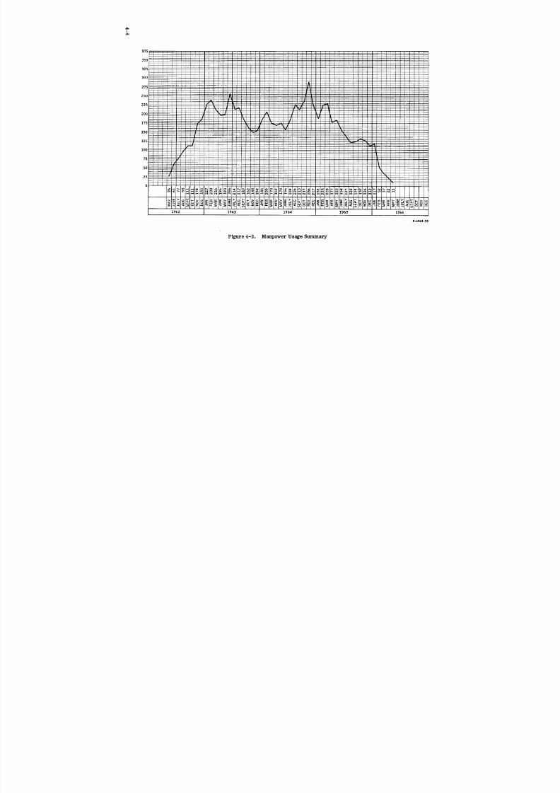
8/6/2019 Little Joe II Test Launch Vehicle NASA Project Apollo. Volume 1 Management
http://slidepdf.com/reader/full/little-joe-ii-test-launch-vehicle-nasa-project-apollo-volume-1-management 83/157
Ioo
C-6062-39
Figure 4-2. Manpower Usage Summary
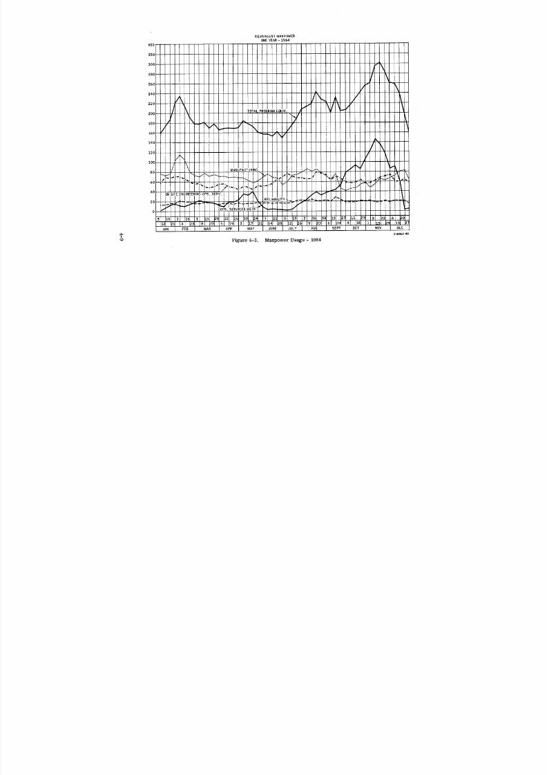
8/6/2019 Little Joe II Test Launch Vehicle NASA Project Apollo. Volume 1 Management
http://slidepdf.com/reader/full/little-joe-ii-test-launch-vehicle-nasa-project-apollo-volume-1-management 84/157
EQUIVALENTMANPOWERONEYEAR- 1964
400
35O
3OO
28O
260
240
220
200
180
160
140
120
100
8O
6O
4O
2O
0
JAN FEB MAR APR MAY JUNE JULY AUG SEPT OCT NOV DEC
:*_ C_06240I
Figure 4-3. Manpower Usage - 1964

8/6/2019 Little Joe II Test Launch Vehicle NASA Project Apollo. Volume 1 Management
http://slidepdf.com/reader/full/little-joe-ii-test-launch-vehicle-nasa-project-apollo-volume-1-management 85/157
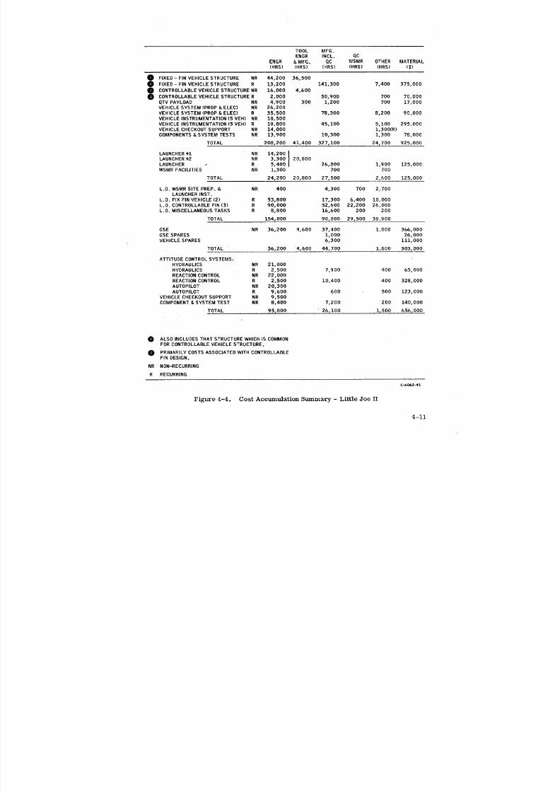
8/6/2019 Little Joe II Test Launch Vehicle NASA Project Apollo. Volume 1 Management
http://slidepdf.com/reader/full/little-joe-ii-test-launch-vehicle-nasa-project-apollo-volume-1-management 86/157
TOOL MFG.
ENGR INCL. QC
ENGR & MFG. QC WSMR OTHER MATERIAL(HRS) (HRS) (HRS) (HRS) (HRS) ($)
0 FIXED - FINVEHICLE STRUCTURE NR 44,200 36,500
FIXED - FIN VEHICLE STRUCTURE R 13,200 141,300 7,400 375,000CONTROLLABLEVEHICLE STRUCTURENR 16,000 4,600
CONTROLLABLEVEHICLE STRUCTURE R 2,000 50,900 700 70,000QTVPAYLOAD NR 4,900 300 1,200 700 17,000VEHICLE SYSTEM (PROP & ELEC) NR 26,200
VEHICLE SYSTEM (PROP& ELEC) R 35,500 78,300 8,200 90,000
VEHICLE INSTRUMENTATION(5 VEH) NR 18,500VEHICLE INSTRUMENTATION (5 VEH) R 19,800 45,100 5,100 295,000
VEHICLE CHECKOUTSUPPORT NR 14,000 1,300(R)
COMPONENTS&SYSTEM TESTS NR 13,900 10,300 1,300 78,000
TOTAL 208,200 41,400 327,100 24,700 925,000
LAUNCHER#1 NR 14,200 [
LAUNCHER#2 NR 3,300 ] 20,800AUNCHER R 5,400 26,800 1,900 125,000
WSMR FACILITIES NR 1,300 700 700
TOTAL 24,200 20,800 27,500 2,600 125,000
L.O. WSMRSITE PREP. & NR 400 4,300 700 2,700LAUNCHERINST.
L.O. FIX FIN VEHICLE (2) R 53,B00 17,300 6,400 10,000
L.O. CONTROLLABLEFIN (3) R 90,000 52,600 22,200 26,000
L.O. MISCELLANEOUSTASKS R 8,800 16,600 200 200
TOTAL 154,000 90,800 29,500 38,900
GSE NR 36,200 4,600 37,400 1,800 366,000GSE SPARES 1,000 26,000
VEHICLE SPARES 6,300 111,000
TOTAL 36,200 4,600 44,700 1,800 503,000
ATTITUDE CONTROLSYSTEMS:
HYDRAULICS NR 21,000HYDRAULICS R 2,500 7,900 400 65,000
REACTIONCONTROL NR 22,000REACTIONCONTROL R 2,500 10,400 400 328,000
AUTOPILOT NR 20,300
AUTOPILOT R 9,600 600 500 123,000
VEHICLE CHECKOUTSUPPORT NR 9,500COMPONENT& SYSTEM TEST NR 8,400 7,200 200 140,000
TOTAL 95,800 26,100 1,500 656r000
0 ALSO INCLUDES THAT STRUCTUREWHICHIS COMMONFORCONTROLLABLEVEHICLE STRUCTURE.
PRIMARILYCOSTS ASSOCIATEDWITH CONTROLLABLEFIN DESIGN.
NR NON-RECURRING
R RECURRING
Cjo062-41
Figure 4-4. Cost Accumulation Summary - Little Joe II
4-11
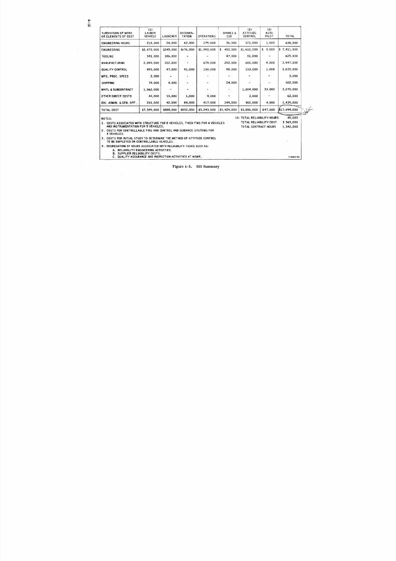
8/6/2019 Little Joe II Test Launch Vehicle NASA Project Apollo. Volume 1 Management
http://slidepdf.com/reader/full/little-joe-ii-test-launch-vehicle-nasa-project-apollo-volume-1-management 87/157
iMab.3
(1) (2) (3)
SUBDIVISIONOF WORK LAUNCH DOCUMEN- SPARES & ATTITUDE AUTO
OR ELEMENTS OF COST VEHICLE LAUNCHER TATION OPERATIONS GSE CONTROL PILOT TOTAL
ENGINEERINGHOURS 215,000 24,000 62,000 179,000 36,000 121,000 1,000 638,000
ENGINEERING $2,475,000 $245,000 $676,000 $1,998,000 $ 400,000 $1,612,000 $ 5,000 $ 7,411,000
TOOLING 341,000 186,000 - - 47,000 51,000 - 625,000
MANUFACTURING 2,094,000 202,000 - 674,000 292,000 681,000 4,000 3,947,000
QUALITY CONTROL 495,000 47,000 91,000 150,000 98,000 153,000 1,000 1,035,000
MFG. PROC. SPECS 3,000 .... 3,000
SHIPPING 74,000 4,000 - - 24,000 - 102,000
MATL &SUBCONTRACT 1,562,000 .... 1,004,000 33,000 3,070,000
OTHERDIRECTCOSTS 44,000 10,000 1,000 4,000 - 3,000 62,000
DIV. ADMIN. &GEN.OFF. 261,000 42,000 84,000 417,000 249,000 382,000 4,000 1,439,000
/TOTALCOST $7,349,000 $888,000 $852,000 $3,243,000 $1,429,000 $3,886,000 $47,000 _17,694,000 _'"
NOTES: (4)TOTAL RELIABILITYHOURS 49,000
1. COSTS ASSOCIATED WITH STRUCTURE FOR8 VEHICLES,FIXED FINSFOR 4 VEHICLES TOTAL RELIABILITYCOST $ 565,000
AND INSTRUMENTATION FOR 5 VEHICLES. TOTAL CONTRACT HOURS 1,342,0002. COSTS FOR CONTROLLABLE FINSAND CONTROL AND GUIDANCE SYSTEMS FOR
4 VEHICLES.
3. COSTS FOR INITIALSTUDY TO DETERMINE THE METHOD OF ATTITUDE CONTROL
TO BE EMPLOYED ON CONTROLLABLE VEHICLES.
4. SEGREGATION OF HOURS ASSOCIATED WITH RELIABILITYTASKS SUCH AS:
A. RELIABILITYENGINEERINGACTIVITIES.
B. SUPPLIERRELIABILITYCOSTS.
C. QUALITYASSURANCEANDINSPECTIONACTIVITIES ATWSMR. c--a062-42
Figure 4-5. 533 Summary

8/6/2019 Little Joe II Test Launch Vehicle NASA Project Apollo. Volume 1 Management
http://slidepdf.com/reader/full/little-joe-ii-test-launch-vehicle-nasa-project-apollo-volume-1-management 88/157
5 DOCUMENTATION SUMMARY

8/6/2019 Little Joe II Test Launch Vehicle NASA Project Apollo. Volume 1 Management
http://slidepdf.com/reader/full/little-joe-ii-test-launch-vehicle-nasa-project-apollo-volume-1-management 89/157
5 I DOCUMENTATION SUMMARY
A. MAJOR DOCUMENTATION
Following is a list of the major Program Documentation and recurring reports
submitted on the Little Joe II program. These documents may be consulted for de-
tailed information on the appropriate functional disciplines and program status:
Program Documentation Report Number
Program Plan GDC 62-177
Launch Vehicle Familiarization Manual CS 63-003
Reliability Program Plan GDC 62-168 (original)
GDC 64-119 (NPC250-1)
Facilities Plan 1st Launch GDC 62-166A
2nd Launch GDC 62-166B
3rd Launch GDC 62-166C
4th Launch Supplement I5th Launch Supplement 11
Test Plan GDC 62-174
Manufacturing Plan GDC 62-205
Support Plan GDC 62-202
Quality Control Plan GDC 62-222
Maintenance Plan GDC 62-281
End Item Test Plan 12-50-1 GDC 62-330
12-50-2 GDC 64-037
12-51-1 GDC 64-233
12-51-2 GDC 64-356
12-51-3 GDC 65-083
5-1
8/6/2019 Little Joe II Test Launch Vehicle NASA Project Apollo. Volume 1 Management
http://slidepdf.com/reader/full/little-joe-ii-test-launch-vehicle-nasa-project-apollo-volume-1-management 90/157
Launch Vehicle Description 12-50 Vehicles GDC 63-034
Manual 12-51-1 GDC 64-236
12-51-2 GDC 64-365
12-51-3 GDC 65-145
Hardware List GDC 62-170
Recurring Documentation
Monthly Progress Reports
Quarterly Progress Reports
Quarterly Reliability Status Report
Monthly Financial Management Report (Form 533)
Monthly Weight and Balance Reports
Monthly Failure Summaries
Monthly Quality Reports
B. NEW DOCUMENTATION
Following is a list of documentation requirements introduced during the course of
the program:
Extended Distribution of Documentation - Documentation to be submitted to a max-
imum of 14 additional NASA agencies and Apollo contractors.
Acceptance Data Package - Documentation delivered with each vehicle. Material
updated as required for final NASA acceptance of vehicle prior to launch.
Recovery Identification Manuals - Identified, by word description and photographs,
components requiring post launch recovery.
Launch Operation Limitations Documents - Contained launch operations limitations
for launch vehicles, launcher, and GSE.
Weekly Reliability Summaries - Summary of all reliability activity during eachweek.
Reliability Assessment Reports - Contained complete reliability assessment for
each vehicle including the following sections:
- Vehicle/Mission Descriptions.
- Reliability Assessment.
- Single Point Failures.
- Anticipated Environmental Conditions.
- Qualification Status.
- Failure Reporting and Corrective Action Summary.
5-2
8/6/2019 Little Joe II Test Launch Vehicle NASA Project Apollo. Volume 1 Management
http://slidepdf.com/reader/full/little-joe-ii-test-launch-vehicle-nasa-project-apollo-volume-1-management 91/157
- Design Review/Open Action Items.
- Development Engineering Inspection/Open Items.
- Operational Time Records.
- Deviations.
- Additional Test Programs.
- Structural Qualifications.
Post Launch Reliability Summary - Summary with particular attention paid to any
unusual incidents. Included proposed corrective action and associated studies in
progress.
Flight Readiness Reports - Contained vehicle description and complete status
report for each subsystem launch complex and GSE. Prepared just prior to launch and
included vehicle certification of readiness for flight.
Operations Requirements Document - Facilities requirements for each launch.
Program Requirements Document - Facilities requirements for the program.
C. SUBMITTAL SCHEDULE
Figure 5-1 shows a typical Little Joe II Documentation Schedule.
D. APPENDIX
Appendix A isa listofalldocumentationprepared for the LittleJoe ]Iprogram.
5-3
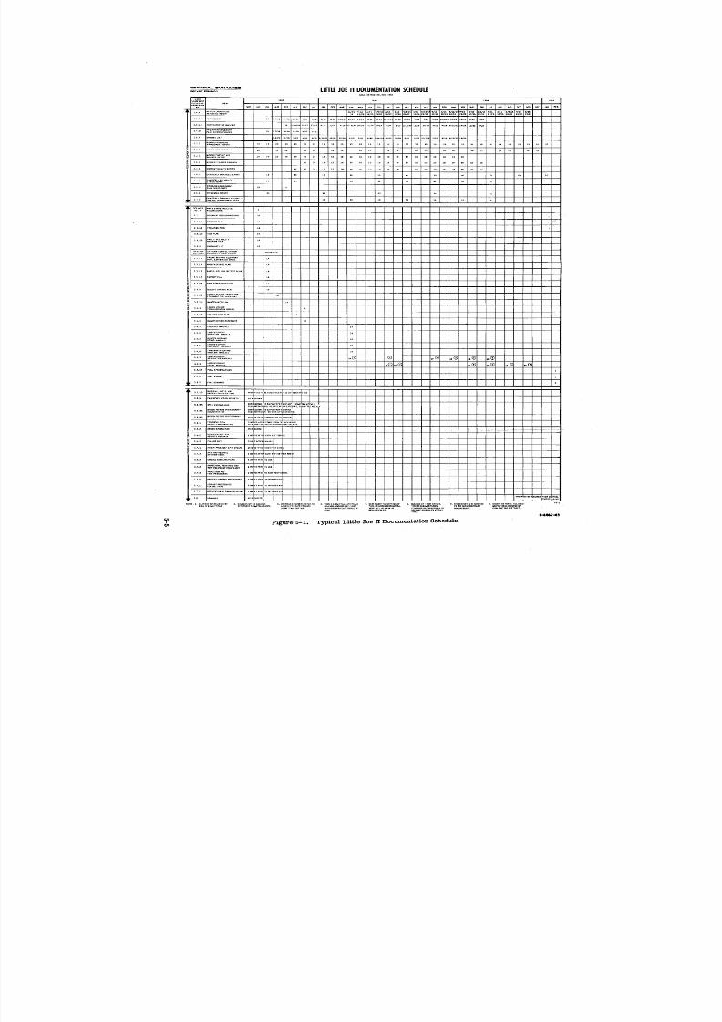
8/6/2019 Little Joe II Test Launch Vehicle NASA Project Apollo. Volume 1 Management
http://slidepdf.com/reader/full/little-joe-ii-test-launch-vehicle-nasa-project-apollo-volume-1-management 92/157

8/6/2019 Little Joe II Test Launch Vehicle NASA Project Apollo. Volume 1 Management
http://slidepdf.com/reader/full/little-joe-ii-test-launch-vehicle-nasa-project-apollo-volume-1-management 93/157
6 [ ASSOCIATED TASKS AND PROPOSALS
8/6/2019 Little Joe II Test Launch Vehicle NASA Project Apollo. Volume 1 Management
http://slidepdf.com/reader/full/little-joe-ii-test-launch-vehicle-nasa-project-apollo-volume-1-management 94/157
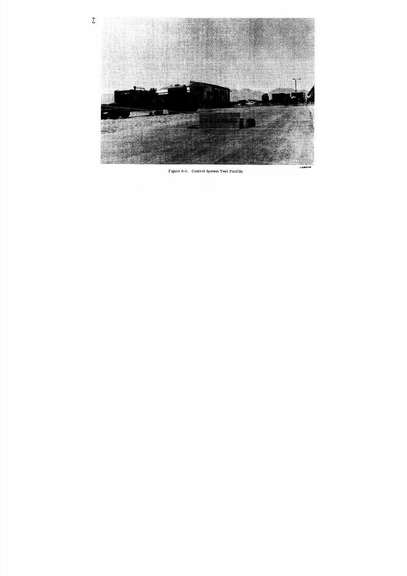
8/6/2019 Little Joe II Test Launch Vehicle NASA Project Apollo. Volume 1 Management
http://slidepdf.com/reader/full/little-joe-ii-test-launch-vehicle-nasa-project-apollo-volume-1-management 95/157
_i!iii
C-b062-44
Figure 6-1. Control System Test Facility

8/6/2019 Little Joe II Test Launch Vehicle NASA Project Apollo. Volume 1 Management
http://slidepdf.com/reader/full/little-joe-ii-test-launch-vehicle-nasa-project-apollo-volume-1-management 96/157
8/6/2019 Little Joe II Test Launch Vehicle NASA Project Apollo. Volume 1 Management
http://slidepdf.com/reader/full/little-joe-ii-test-launch-vehicle-nasa-project-apollo-volume-1-management 97/157
shrouds and adapters to be used with Little Joe II in testing the LEM propulsion sys-
tems. NASA subsequently decided not to flight test these systems prior to use on theSaturn.
Proposing to the Air Force Space Systems Division, in 1963, the use of Little Joe
]1 to test the Dyna Soar control and characteristics in its re-entry corridor prior to
orbital flights. This'was dropped when the Dyna Soar program was cancelled.
Providing, in August 1963, flight performance and costs in response to a request
from the Gemini Project Office of NASA/MSC who was considering the feasibility of
suborbitally testing the Gemini abort escape system and heat shield prior to Titan
flights. The Gemini office decided to rely on sled testing for this purpose.
Working with NASA/MSFC in late 1962 on the feasibility of using a modified or
growth version of Little Joe II for suborbitally testing the Multi-Mission Module. This
effort ended when the MSFC program was cancelled.
Assisting the Ryan Aeronautical Company in preparing arLd submitting an unsolic-
ited proposal No. 63B017, dated 20 March 1963, to NASA/MSFC. This proposed theuse of Little Joe II as a test vehicle to prove the feasibility of using the flexible wing
principle in recovering Saturn boosters. No action was taken by NASA/MSFC to allot
funds and pursue the concept.
Working with NASA/WSMR and NASA/MSFC in 1965 on the possible use of Little
Joe II as a basic part of a 1/3-scale simulation of the Saturn V to obtain in-flight infor-
mation on airflow instability and resultant acoustic effect. NASA/MSFC eventually
decided to attempt to obtain this type of data by wind tunnel testing.
Proposing to NASA/LRC in 1965 the use of the booster axLd surplus Minuteman
vehicles to create a relatively low-cost, medium payload orbiLtal booster to replace
the Scout and some of the Thor versions. NASA/Headquarters did not agree with the
desirability of such a program, although it is understood that NASA/LRC did some
study work, with favorable results, on the subject.
Cooperating with JPL, NASA/LRC, AVCO and other contractors associated with
the Mars Mariner program in evaluating the use of the vehicle to test the "probe" and
the "lander" at high altitudes simulating Mars atmospheric density. This application
is still under consideration.
Supporting an investigation by NASA/FRC on the use of the vehicle for in-flight
testing of the M-2. A NASA report TM-X-56006 dated 1964 summarized the results of
the investigation and concluded, it is understood, that the plm_ was feasible and desir-able. The present status or future of this plan is unknown.
Working with various contractors and the Air Force Space Systems Division to
investigate the practicality of using Little Joe II to test the Gemini abort system when
used on conjunction with the MOL. It is understood that this possibility is still under
consideration by some elements in the MOL program.
6-4

8/6/2019 Little Joe II Test Launch Vehicle NASA Project Apollo. Volume 1 Management
http://slidepdf.com/reader/full/little-joe-ii-test-launch-vehicle-nasa-project-apollo-volume-1-management 98/157
Providing, in 1963, information to the General Electric Company to assist them
in proposing the use of the booster to the Air Force for pre-orbital flight testing of a
hypersonic ram jet airplane. This program was stretched out and it is assumed that
this proposal is still being considered.
Supporting NASA/MSFC since early 1965 in their consideration of using Little Joe
II to demonstrate and evaluate the principle of recovery and reuse of Saturn I-C stages
utilizing parachutes. This program is still under consideration.
Many other contacts have been made by visit and correspondence to all NASA
agencies, SSD, BSD, ARPA, NRL, SANDIA and various contractors working with
these agencies. Discussions were also held with Australian and Mexican officials.
To support this activity, Convair has prepared and distributed two sales brochures;
Little Joe Performance Capabilities (GD/C-65-197 dated September 1965) and Little
Joe II Future Potential dated June 1965. Convair is continuing, with the assistance of
NASA, to respond to inquiries on specific application possibilities.
6-5

8/6/2019 Little Joe II Test Launch Vehicle NASA Project Apollo. Volume 1 Management
http://slidepdf.com/reader/full/little-joe-ii-test-launch-vehicle-nasa-project-apollo-volume-1-management 99/157
7 [ ACHIEVEMENTS
8/6/2019 Little Joe II Test Launch Vehicle NASA Project Apollo. Volume 1 Management
http://slidepdf.com/reader/full/little-joe-ii-test-launch-vehicle-nasa-project-apollo-volume-1-management 100/157
7 I ACHIEVEMENTS
A. REPORTING OF NEW TECHNOLOGY
The new General Provisions that were incorporated in the initial Little Joe II con-
tract includes a "Reporting of New Technology" clause and a revised "Property Rights
in Invention" clause. The procedure devised to monitor this contractual requirement
is covered by Project Memorandum 12-E-6, in the Little Joe II Project Manual. In
accordance with this procedure, a program monitor was made responsible for the re-
view of design drawings, Engineering design notebooks, Industrial Engineering history
folders and related manufacturing processes, on a regular basis for reportable items.
Reports were submitted on a semiannual basis, with a final report upon completion of
contract work. All reportable items were reviewed with Convalr's Patent Counsel
prior to submittal to NASA. The procedure further defined the requirement be im-
posed on subcontractors having purchase orders in excess of $50,000.
The program monitor for this activity was always a member of the Little Joe II
Project Office, and, as such, constantly reviewed all changes and new designs. This
assignment, with the previously described review responsibilities, ensured that all
reportable items were identified.
The Little Joe II program was based on engineering a product around conventional
structural and off-the-shelf components. Therefore, only two new technology items
were developed and reported during the span of the contract. These were:
TIMER-LAUNCHER SEQUENCE, CONVAIR P/N 12-61325-3
The launching sequence timer was designed to fill the need for a combined count-
down time display light control and propulsion ignition control that were positively
synchronized. This timer synchronizes the countdown lights and ignition, and subse-
quent timing of the second stage propulsion motors during flight. See Figures 7-1 and7-2 for timer illustrations. A basic timer diagram and its operation is shown in
Figure 7-3.
Control switches on the countdown console permitted holding the countdown at any
desired time but retained the countdown time display lights at the time of stoppage.
Continuance of countdown could be resumed from the point of interruption, or reset to
the starting point could be accomplished by energizing the reset circuit.
7-1
8/6/2019 Little Joe II Test Launch Vehicle NASA Project Apollo. Volume 1 Management
http://slidepdf.com/reader/full/little-joe-ii-test-launch-vehicle-nasa-project-apollo-volume-1-management 101/157
C,-6062..45
Figure 7-1. Launch Sequence Timer
C-0062-46
Figure 7-2. Launch Sequence Timer - Internal View
7-2
8/6/2019 Little Joe II Test Launch Vehicle NASA Project Apollo. Volume 1 Management
http://slidepdf.com/reader/full/little-joe-ii-test-launch-vehicle-nasa-project-apollo-volume-1-management 102/157
8/6/2019 Little Joe II Test Launch Vehicle NASA Project Apollo. Volume 1 Management
http://slidepdf.com/reader/full/little-joe-ii-test-launch-vehicle-nasa-project-apollo-volume-1-management 103/157
The timer has many applications in industry where one-second timing intervals
are adequate. Modification to increase the frequency of the pulse generator to ten per
second would reduce the intervals to one-tenth of a second if a more precise timing
was required.
BASE THERMAL PROTECTION
This is a method of applying a heat insulating material to aluminum alloy surfaces
having severe irregularities, and using a curing heat cycle which is compatible with
aluminum alloy limitations. Pre-molding the insulating material is not necessary.
See Figures 7-4 and 7-5 for views of fin and vehicle base insulation.
The combination of insulating material and adhesive agent, and the application
procedure, was developed specifically to provide thermal protection for the base sur-
faces of the Little Joe II Test Booster from the heat of the engine jets during flight.
The insulating material was Dow Coming Uncured Silicone Rubber DC6510 and the
adhesive agent was Union Carbide Silicone Primer Y-3395 or Y-3459. Rubber and/or
primer produced by other companies were tried and found effective, but the selected
combination proved most satisfactory in the test conducted under Little Joe H condi-
tions.
C.-6062--48
Figure 7-4. Fin Insulation - installing Vacuum Blanket
7-5

8/6/2019 Little Joe II Test Launch Vehicle NASA Project Apollo. Volume 1 Management
http://slidepdf.com/reader/full/little-joe-ii-test-launch-vehicle-nasa-project-apollo-volume-1-management 104/157
C-6062--49
Figure 7-5. Afterbody Insulation After Baking
The installation process consisted of the following: thoroughly cleaning the sur-
face, roughing it with a wire brush or similar abrasive, recleaning, applying a primer
with a brush, allowing to dry, and applying the uncured ru.bber by adding layers as
required to achieve the desired thickness over the metal _urfaees. Uniform pressurewas applied to the entire covered area by vacuum or other means; the area was heated
to 250°F and held for 30 minutes and then allowed to cool, with pressure maintained.
The finished product was a soft, tough rubber (appro_:imately 30 shore hardness)
tenaciously bonded to the aluminum alloy base. When exposed to high temperature the
exposed surface would char, but the back surface would remain cool. The thickness
required was determined by the rate at which the rubber _vould char in the environment
to which it was exposed. Apparent future applications are for thermal protection,
insulation, or protection of surfaces against corrosive elements to which the semi-
curing silicone rubber is resistant.
LISTING OF SUBCONTRACTORS AFFECTED
Reporting of New Technology and Property Rights in :Inventions clauses were in-
cluded in the purchase order to Walter Kidde Company, Belleville, New Jersey, and
Whittaker Corporation, Controls & Guidance Division, Chatsworth, California. Per-
formanee of work on these purchase orders did not produce any new technology.
7-6

8/6/2019 Little Joe II Test Launch Vehicle NASA Project Apollo. Volume 1 Management
http://slidepdf.com/reader/full/little-joe-ii-test-launch-vehicle-nasa-project-apollo-volume-1-management 105/157
_B_'_ ''FIRSTS''A number of achievements on this program represented a "first time," at time of
accomplishment, in the United States space program. Some of these were:
1) Little Joe II represented the largest diameter vehicle launched by the United
States at the time of its first flight.
2) Little Joe II's thrust and weight were the highest ever associated
with all-solid-propellant booster.
3) Little Joe II's gross payload of 38,200 pounds (including ballast) was the largest
lifted on a launch vehicle.
4) The thrust of the reaction control motors was the highest ever flown at the
time of the first attitude control vehicle.
5) Little floe II's first launching was the first self-propelled flight test accom-
plished on the Apollo Program.
6) The corrugated structure of the vehicle was independently conceived and it
was the first time it had been proven in flight.
7) On the 12-51-3 Little Joe II flight, Algol motors were ignited at an altitude
and in flight for the first time.
8) This vehicle was the first all-aluminum launch vehicle utilizing an ablative
rubber for base heat protection.
9) The Little Joe II program was the first to execute a planned catastrophe in
flight (thrust termination) to prove an abort system under an actual flight con-
dition which required a safe abort.
10) The last flight was the highest altitude an abort system has ever been tested.
11) The Little Joe II vehicle was the first vehicle to employ three Algol motors in
a cluster configuration.
C. INNOVATIONS
The followingmethods ofoperationwere developed duringthe LittleJoe IIpro-
gram and subsequentlyadoptedby otherNASA Apollo program contractors.
PERT DATA TRANSCEIVER SYSTEM
PERT updateand analysisreportswere originallysubmittedtoNASA/MSC by
teletypeevery two weeks, startinginSeptember 1962. The update reportsproved un-
satisfactorydue tolengthypreparation,processing and transmittaltime. A data
transeeiversystem installedin October 1962 provideddireetcard-to-cardtransmittal
by use of a data-phone. This system substantially reduced overall transmittal and
7-7
8/6/2019 Little Joe II Test Launch Vehicle NASA Project Apollo. Volume 1 Management
http://slidepdf.com/reader/full/little-joe-ii-test-launch-vehicle-nasa-project-apollo-volume-1-management 106/157
processing time and eliminated update errors experienced by the manual method.
Other NASA Apollo Program contractors subsequently implemented this system.
OPERATIONAL CHECKOUT PROCEDURES
Procedures for vehicle systems checkout were initially written to a Convair format
which assumed a high degree of technical expertise by the operators. Although thisconcept proved satisfactory for factory checkout on the first vehicle, it deviated too
widely from the procedures which had previously been used by NASA at other launchsites.
NASA, with the cooperation of Convair, NAA and Cape Kennedy personnel, out-
lined a set of ground rules for procedure writing. The ensuing rough draft was desig-
nated Apollo Procedure No. 1 (AP-1) and was reviewed by management, engineers and
operators. Comments were returned to NASA/MSC. AP-1 was completely revised to
accommodate the operational methods required for the Apollo program; the revised
document was entitled, Apollo Documentation Procedure No. 2, Standard for the
Preparation of Operational Checkout Procedures (AP-2). The AP-2 format specifiedexact location, nomenclature, time sequence and operator for any given operational
step. This format theoretically enabled operational performance by relatively inex-
perienced personnel. With the introduction of the AP-2 specification, all Convair
procedures were created by electronic data processing (EDP). The EDP permitted
tape storage of finished documentation and also simplified changes and reproduction.
In common with other detailed specifications of this type, certain waivers were
required, to fit the AP-2 format to the particular electronic data processes used by
Convair. This detailed AP-2 procedure continues in use by other NASA contractors.

8/6/2019 Little Joe II Test Launch Vehicle NASA Project Apollo. Volume 1 Management
http://slidepdf.com/reader/full/little-joe-ii-test-launch-vehicle-nasa-project-apollo-volume-1-management 107/157
8 PROGRAM CLOSE-OUT STATUS

8/6/2019 Little Joe II Test Launch Vehicle NASA Project Apollo. Volume 1 Management
http://slidepdf.com/reader/full/little-joe-ii-test-launch-vehicle-nasa-project-apollo-volume-1-management 108/157
8 PROGRAM CLOSE.OUT STATUS
A. GENERAL
Convair and NASA, late in 1965, recognized the need for a plan to effect an
orderly close out of the Little Joe II program. The plan provided a single source
document which brought together all pertinent information, defining departmental
action and identifying the procedures governing the action. The document further
provided a schedule for the efficient close out of Contract NAS 9-492. (Reference
GD/C 66-020, Contract Close'Out Plan, NASA Project Apollo - Little Joe II Project).
By NASA direction, terminal close out of the program was modified to the extent
that existing vehicles and significant GFP components and materials would be stored
through the year 1966. Storage of these materials was based on the premise of
possible reactivation of Convair San Diego and WSMR facilities for additional launches
of the Little Joe II. NASA's Contract Change Authorization (CCA) #96 and Revision #1
thereto provided contractual direction. Arrangements were made by NASA to store
the Little Joe 1"[vehicles in Air Force Plant 19 in San Diego. See Figure 8-1 for views
of storage area. Vehicles 12-50-3, 12-50-4 and 12-51-4 are preserved and stored in
Mylar bags. Suitable desiccant bags are used to control moisture content. All tooling,
GSE and GFP equipment has been preserved, packaged, and stored with the vehicles.
Launcher 12-60-2 is preserved and stored in place in Convair's Experimental Depart-ment' s Yard.
Materials that were not retained for future use were forwarded to Disposition
Stores. These materials were surveyed by DCASPRO for final disposition action.
There are 1500 outside purchased (OSP) line items and 200 material items with an
extended value of under $100 which have been processed. There are 250 outside
purchased (OSP) and 30 miscellaneous items with an extended value of over $100 which
have been assigned to a disposition schedule and circulated to other government
agencies for possible use.
All drawings, specifications and reports of contractural requirement have been
microfilmed and forwarded to NASA/MSC.
Convair activity at WSMR was closed out on 23 March 1966. Launcher 12-60-1
has been stored in place at WSMR, Launch Complex 36. All launcher storable and
other disposable materials were turned over to ZIA, a WSMR on-site NASA contractor.
NASA is responsible for maintenance of Launcher 12-60-1. Those GFP materials
required for reactivation of Little Joe II were returned to Convair, San Diego, for
preservation and storage.
8-1
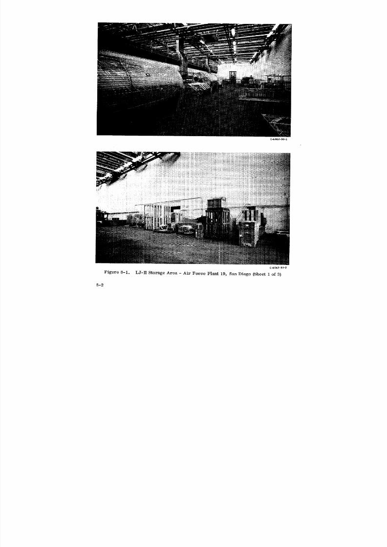
8/6/2019 Little Joe II Test Launch Vehicle NASA Project Apollo. Volume 1 Management
http://slidepdf.com/reader/full/little-joe-ii-test-launch-vehicle-nasa-project-apollo-volume-1-management 109/157
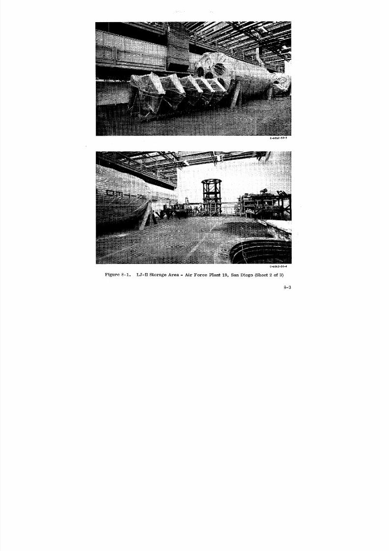
8/6/2019 Little Joe II Test Launch Vehicle NASA Project Apollo. Volume 1 Management
http://slidepdf.com/reader/full/little-joe-ii-test-launch-vehicle-nasa-project-apollo-volume-1-management 110/157
CJo062-50-_
C=6062-50-4
Figure 8-1. LJ-II Storage Area - Air Force Plant 19, San Diego (Sheet 2 of 3)
8-3
8/6/2019 Little Joe II Test Launch Vehicle NASA Project Apollo. Volume 1 Management
http://slidepdf.com/reader/full/little-joe-ii-test-launch-vehicle-nasa-project-apollo-volume-1-management 111/157
C,-6062-50-5
Figure 8-1. LJ-II Storage Area - Air Force Plant 19, San Diego (Sheet 3 of 3)
Maintenance of those items stored in Air Force Plant 19 in San Diego has been
negotiated as a separate contract with Convair and extends through 1966.
8-4

8/6/2019 Little Joe II Test Launch Vehicle NASA Project Apollo. Volume 1 Management
http://slidepdf.com/reader/full/little-joe-ii-test-launch-vehicle-nasa-project-apollo-volume-1-management 112/157
9 RECOMMENDATIONS
8/6/2019 Little Joe II Test Launch Vehicle NASA Project Apollo. Volume 1 Management
http://slidepdf.com/reader/full/little-joe-ii-test-launch-vehicle-nasa-project-apollo-volume-1-management 113/157
9 RECOMMENDATIONS
The success of the Little Joe II program suggests that the various philosophies
set forth in this management volume should be considered for integration into future
programs of similar complexity and scope. More specific recommendations are de-
fined in the following paragraphs.
Customer's Technical Direction - Single source direction in this field provides
the key for a clear communications link. Clear communication insures rapid responseto change action, minimizes the fog factor and promotes efficient and economical
operations.
Customer Approved Sources - It is incumbent on the contractor that these sources
be frequently re-evaluated to assure that procedures, practices and skill levels are in
accordance with the Customer's requirements. Furthermore, the Customer should
maintain intensive surveillance of the approved sources to assure that their credentials
remain current.
Customer Specification and Documentation Requirements - The contractor should
frequently review Customer imposed specifications and contractual requirements in
terms of program application. He should determine whether imposed requirements
are warranted in relation to the program cost and schedule effect. For example, the
NASA GSE specification MSC-GSE-1A requires a separate specification and formal
drawing for each individual piece of equipment. In many cases the time involved in
preparing specifications and drawings and obtaining approval of them far outweighs the
cost of the individual piece of GSE. Waivers to specifications and the use of blanket
specifications can materially reduce end item cost and realization time. The Little
Joe II resolution of this problem is discussed in detail in Volume II, Section 4. D, GSE
Documentation, of this report.
The docume_ation distribution generally imposed on a contractor should be evalu-
ated for real necessity. In many eases distribution may be minimized and thus4_
economy realized.
Centralized Control of Testing Activities - Control of qualification and system test-
ing was vested in the Reliability Group. By combining all testing activity under the
cognizance of one group, efficiency and economy were realized. The inherent char-
acter and philosophy of reliability engineers assures an ideal guardianship for the
testing activities.
9-1
8/6/2019 Little Joe II Test Launch Vehicle NASA Project Apollo. Volume 1 Management
http://slidepdf.com/reader/full/little-joe-ii-test-launch-vehicle-nasa-project-apollo-volume-1-management 114/157

8/6/2019 Little Joe II Test Launch Vehicle NASA Project Apollo. Volume 1 Management
http://slidepdf.com/reader/full/little-joe-ii-test-launch-vehicle-nasa-project-apollo-volume-1-management 115/157
10 CONCLUSIONS

8/6/2019 Little Joe II Test Launch Vehicle NASA Project Apollo. Volume 1 Management
http://slidepdf.com/reader/full/little-joe-ii-test-launch-vehicle-nasa-project-apollo-volume-1-management 116/157
10 [ CONCLUSIONS
The Little Joe II program provided a low-cost launch vehicle which was adaptable
to a wide range of mission requirements. The recent test series which successfully
proved the capability of the Apollo launch escape system used only a part of the launch
vehicle capability; thus, the creation of Little Joe II not only enabled accomplishment
of a major milestone for the Apollo program but established a capability for future
sub-orbital programs.
10-1

8/6/2019 Little Joe II Test Launch Vehicle NASA Project Apollo. Volume 1 Management
http://slidepdf.com/reader/full/little-joe-ii-test-launch-vehicle-nasa-project-apollo-volume-1-management 117/157
11 [ BIBLIOGRAPHY
8/6/2019 Little Joe II Test Launch Vehicle NASA Project Apollo. Volume 1 Management
http://slidepdf.com/reader/full/little-joe-ii-test-launch-vehicle-nasa-project-apollo-volume-1-management 118/157
11 I BIBLIOGRAPHY
(Aerojets) Interface Control Document, Report Number 0667-TICD-1 dated 1 July 1963.
Contract Close-Out Plan, NASA Project Apollo - Little Joe II Project, GD/C 66-020.
DD 1446 Form (entitled:) Contractor Performance and Evaluation, General Dynamics/
Convair, Contract NAS9-492, dated 12 June 1964.
D. I.B.-12-015.
Documentation Requirements of Contract NAS 9-150.
Hardware List, Little Joe 11 Project, GDC-62-170.
Interface Control Document, Mission A-0Ol, Little Joe II Vehicle 12-50-2 and Payload
Boilerplate 12 (BP-12) Document Number MH01-04010-414 dated 17 March 1964.
Interface Control Document, Mission A-002, Little Joe II Vehicle 12-51-1 and BP-23,
Document Number MH01-04012 dated 6 October 1964.
Interface Control Document, Mission A-003, Little Joe II Vehicle 12-51-2 and BP-22,
Document Number MH01-04011-414 dated 30 March 1965.
Interface Control Document, Mission A-004, Little Joe II Vehicle 12-51-3 and Space-
craft 002 (SC-002), Document Number MH01-04013-414 dated 6 August 196S.
Letter 11-1-1486, dated 20 April 1962.
Little Joe II Future Potential dated June 1965.
Little Joe Performance Capabilities, GD/C-65-197 dated September 1965.
Memorandum of Understanding, June 1963, revised February 1964.
NASA Contract Change Authorization (CCA) No. 96, and Revision No. 1.
NASA Project Apollo Test Launch Vehicle, Little Joe H - Technical Proposal,
GDC-62-114, dated April 1962.
NASA Quality Publication - Inspection System Provisions for Suppliers of Space
Materials, Parts, Components, and Services, NPC-200-3, April 1965 Edition.
NASA Quality Publication - Quality Program Provisions for Space System Contractors,
N1_-200-2 dated April 20, 1962.
NASA Quality Publication NPC 200.
11-1
8/6/2019 Little Joe II Test Launch Vehicle NASA Project Apollo. Volume 1 Management
http://slidepdf.com/reader/full/little-joe-ii-test-launch-vehicle-nasa-project-apollo-volume-1-management 119/157
BIBLIOGRAPHY (CONTINUED)
NASA/MSC Request for Proposal MSC-62-39P, dated 6 April 1962.
NASA Statement of Work for Suborbital Test Launch Vehicle System, GDC-62-361,dated 20 November 1962.
Project Memorandum 12-E-6, in Little Joe II Project Manual.
Reliability Program for Systems, Subsystems, and Equipment, MIL-R-27542 (USAF).
Reliability Program Plan (NPC 250-1), GD/C 64-119.
Soldering Specification MSFC-PROC 158B.
Support Plan - Test Launch Vehicle - Little Joe H, GDC-62-202, dated 21 Sept. 1962.
11-2

8/6/2019 Little Joe II Test Launch Vehicle NASA Project Apollo. Volume 1 Management
http://slidepdf.com/reader/full/little-joe-ii-test-launch-vehicle-nasa-project-apollo-volume-1-management 120/157
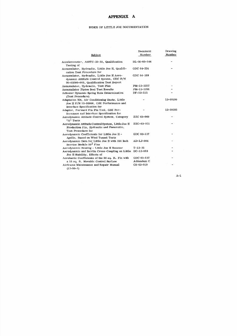
8/6/2019 Little Joe II Test Launch Vehicle NASA Project Apollo. Volume 1 Management
http://slidepdf.com/reader/full/little-joe-ii-test-launch-vehicle-nasa-project-apollo-volume-1-management 121/157
APPENDIX A
INDEX OF LITTLE JOE DOCUMENTATION
Document Drawing
Number Number
Accelerometer, A69TC-20-30, Qualification DL-M-63-144
Testing of
Accumulator, Hydraulic, Little Joe II, Qualifi- GDC 64-224
cation Test Procedure for
Accumulator, Hydraulic, Little Joe II Aero- GDC 64-319
dynamic Attitude Control System, GDC P/N
90-03500-003, Qualification Test Report
Accumulator, Hydraulic, Test Plan PM-12-2217 -
Accumulator Piston Seal Test Results PM- 12- 2291 -
Actuator Dynamic Spring Rate Determination DF-12-115
(Test Procedure)
Adaptation Kit, Air Conditioning Ducts, Little - 12-09290
Joe II P/N 12-93006, GSE Performance and
Interface Specification forAdapter, Forward Fin Pin Tool, GSE Per- - 12-09285
formance and Interface Specification for
Aerodynamic Attitude Control System, Category ZZC 63-060
"A" Tests
Aerodynamic AttitudeControlSystem, LittleJoe II ZZC-63-011
Production Fin, Hydraulic and Pneumatic,
Test Procedure for
Aerodynamic Coefficients for Little Joe II - GDC 63-137
Apollo, Based on Wind Tunnel Tests
Aerodynamic Data for Little Joe H with 316 Inch AD-LJ-004
Service Module 502 Fins
Aerodynamic Heating - Little Joe II Booster T-12-25
Aerodynamic and Inertia Cross-Coupling on Little DC-12-018
Joe II Stability, Effects of
Aerolastic Coefficients of the 50 sq. ft. Fin with GDC 63-137
a 15 sq. ft. Movable Control Surface Addendum C
Airframe Maintenance and Repair Manual CS-63-010 -
(12-50-1)
A-1
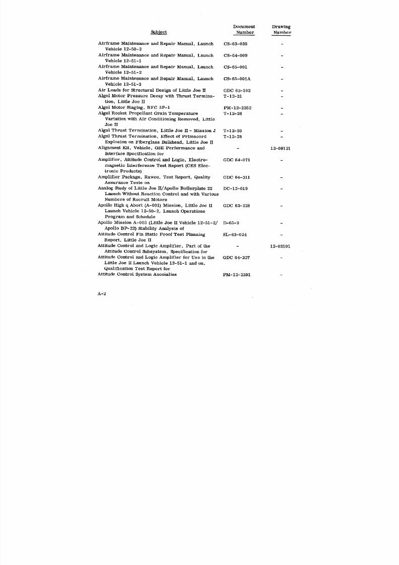
8/6/2019 Little Joe II Test Launch Vehicle NASA Project Apollo. Volume 1 Management
http://slidepdf.com/reader/full/little-joe-ii-test-launch-vehicle-nasa-project-apollo-volume-1-management 122/157
Document Drawing
Number Number
Airframe Maintenance and Repair Manual, Launch CS-63-035
Vehicle 12-50-2
Airframe Maintenance and Repair Manual, Launch CS-64-009
Vehicle 12-51-1
Airframe Maintenance and Repair Manual, Launch CS-65-001
Vehicle 12-51-2
Airframe Maintenance and Repair Manual, Launch CS-65-001AVehicle 12-51-3
Air Loads for Structural Design of Little Joe H GDC 63-102 -
Algol Motor Pressure Decay with Thrust Termina- T-12-31
tion, Little Joe H
Algol Motor Staging, RFC 5P-I PM-12-2252 -
Algol Rocket Propellant Grain Temperature T-12-26 -
Variation with Air Conditioning Removed, LittleJoe II
Algol Thrust Termination, Little Joe II - Mission J T-12-30
Algol Thrust Termination, Effect of Primacord T-12-28
Explosion on Fiberglass Bulkhead, Little Joe H
Alignment Kit, Vehicle, GSE Performance and - 12-09121
Interface Specification for
Amplifier, Attitude Control and Logic, Electro- GDC 64-071
magnetic Interference Test Report (CES Elec-
tronic Products}
Amplifier Package, Rawco, Test Report, Quality GDC 64-311Assurance Tests on
Analog Study of Little Joe H/Apollo Boilerplate 22 DC-12-019
Launch Without Reaction Control and with Various
Numbers of Recruit Motors
Apollo High q Abort (A-001) Mission, Little Joe II GDC 63-228
Launch Vehicle 12-50-2, Launch Operations
Program and Schedule
Apollo Mission A-003 (Little Joe II Vehicle 12-51-2/ D-65-9
Apollo BP-22) Stability Analysis of
Attitude Control Fin Static Proof Test Planning SL-63-024
Report, Little Joe IIAttitude Control and Logic Amplifier, Part of the 12-03101
Attitude Control Subsystem, Specification for
Attitude Control and Logic Amplifier for Use in the GDC 64-327
Little Joe H Launch Vehicle 12-51-1 and on,
Qualification Test Report for
Attitude Control System Anomalies PM-12-2391 -
A-2
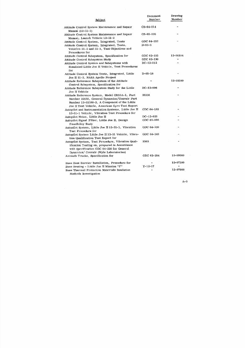
8/6/2019 Little Joe II Test Launch Vehicle NASA Project Apollo. Volume 1 Management
http://slidepdf.com/reader/full/little-joe-ii-test-launch-vehicle-nasa-project-apollo-volume-1-management 123/157
Document Drawing
_b]ect Number Number
Attitude Control System Maintenance and Repair CS-64-014
Manual (12-51-1)
Attitude Control System Maintenance and Repair CS-65-006
Manual, Launch Vehicle 12-51-2
•Attitude Control System, Integrated, Tests GDC 64-332 -
Attitude Control System, Integrated, Tests, D-65-5
Vehicles 51-2 and 51-3, Test Objectives and
Procedures for
Attitude Control Subsystem, Specification for GDC 62-335 12-06104
Attitude Control Subsystem Study GDC 62-190
Attitude Control System and Subsystems with DC-12-012
Simulated Little Joe H Vehicle, Test Procedures
for
Attitude Control System Tests, Integrated, Little D-65-18Joe II 51-2, NASA Apollo Project
Attitude Reference Subsystem of the Attitude - 12-03100
Control Subsystem, Specification for
Attitude Reference Subsystem Study for the Little DC-12-006
Joe II Vehicle
Attitude Reference System, Model GR10A-1, Part 26336
Number 22650, General Dynamics/Convair Part
Number 12-03100-3, A Component of the Little
Joe II Test Vehicle, American Gyro Test Report
Aut0pilot and Instrumentation Systems, Little Joe II GDC 64-189
12-51-1 Vehicle, Vibration Test Procedure for
Autopilot Noise, Little Joe II DC-12-020 -
Autopilot Signal Filter, Little Joe H, Design GDC 65-098 -
Feasibility Study
Autopilot System, Little Joe II 12-51-1, Vibration GDC 64-230
Test Procedure for
Autopilot System Little Joe II 12-51 Vehicle, Vibra- GDC 64-340
tion Qualification Test Report for
Autopilot System, Test Procedure, Vibration Qual- 3503
ification Testing on, prepared in Accordance
with Specification GDC 64-230 for General
Dynamics/ Convair (Wyle Laboratories}
Azimuth Trucks, Specification for GDC 62-284 12-09260
Base Heat Barrier Installation, Procedure for - 12-07100
Base Heating - LittleJoe IIMission "F" T-12-17 -
Base Thermal ProtectionMaterials Insulation - 12-07000
Methods Investigation
A-3
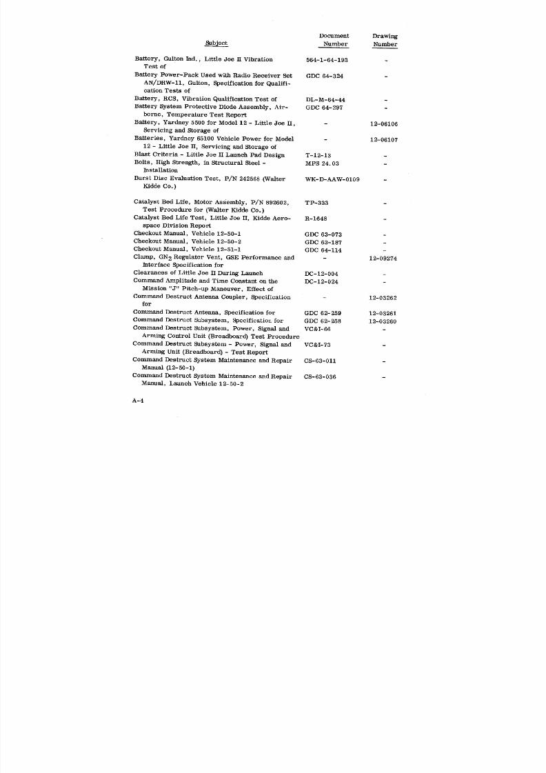
8/6/2019 Little Joe II Test Launch Vehicle NASA Project Apollo. Volume 1 Management
http://slidepdf.com/reader/full/little-joe-ii-test-launch-vehicle-nasa-project-apollo-volume-1-management 124/157
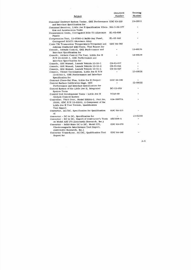
8/6/2019 Little Joe II Test Launch Vehicle NASA Project Apollo. Volume 1 Management
http://slidepdf.com/reader/full/little-joe-ii-test-launch-vehicle-nasa-project-apollo-volume-1-management 125/157
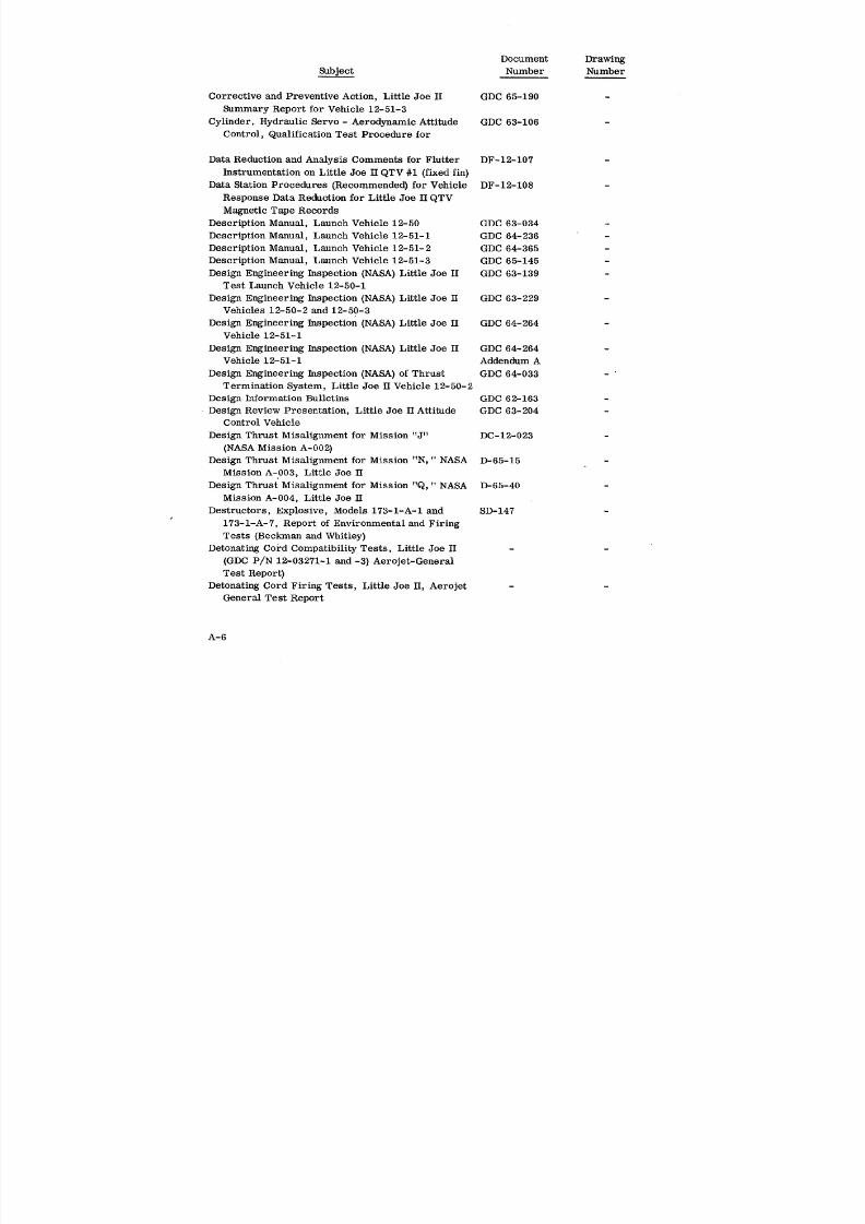
8/6/2019 Little Joe II Test Launch Vehicle NASA Project Apollo. Volume 1 Management
http://slidepdf.com/reader/full/little-joe-ii-test-launch-vehicle-nasa-project-apollo-volume-1-management 126/157
Document Drawing
Subject Number Number
Corrective and Preventive Action, Little Joe H GDC 65-190 -
Summary Report for Vehicle 12-51-3
Cylinder, Hydraulic Servo- Aerodynamic Attitude GDC 63-106
Control, Qualification Test Procedure for
Data Reduction and Analysis Comments for Flutter DF-12-107
Instrumentation on Little Joe II QTV #1 (fixed fin)
Data Station Procedures (Recommended) for Vehicle DF-12-108
Response Data Reduction for Little Joe II QTV
Magnetic Tape Records
Description Manual, Launch Vehicle 12-50 GDC 63-034 -
Description Manual, Launch Vehicle 12-51-1 GDC 64-236 -
Description Manual, Launch Vehicle 12-51-2 GDC 64-365 -
Description Manual, Launch Vehicle 12-51-3 GDC 65-145 -Design Engineering Inspection (NASA) Little Joe H GDC 63-139
Test Launch Vehicle 12-50-1
Design Engineering Inspection (NASA) Little Joe IT GDC 63-229
Vehicles 12-50-2 and 12-50-3
Design Engineering Inspection (NASA) Little Joe II GDC 64-264Vehicle 12-51-1
Design Engineering Inspection (NASA) Little Joe H GDC 64-264
Vehicle 12-51-1 Addendum A
Design Engineering Inspection (NASA) of Thrust GDC 64-033
Termination System, Little Joe H Vehicle 12-50-2
Design Information Bulletins GDC 62-163 -
Design Review Presentation, Little Joe ITAttitude GDC 63-204
Control Vehicle
Design Thrust Misalignment for Mission "J" DC-12-023 -
(NASA Mission A-002)
Design Thrust Misalignment for Mission "N, " NASA D-65.-15
Mission A-003, Little Joe H
Design Thrust Misalignment for Mission "Q," NASA D-65-40
Mission A-004, Little Joe II
Destructors, Explosive, Models 173-1-A-1 and SD-147
173-1-A-7, Report of Environmental and Firing
Tests (Beckman and Whitley)
Detonating cord Compatibility Tests, Little Joe H - -
(GDC P/N 12-03271-1 and -3) Aerojet-General
Test Report)
Detonating Cord Firing Tests, Little Joe II, Aerojet -
General Test Report
A-6

8/6/2019 Little Joe II Test Launch Vehicle NASA Project Apollo. Volume 1 Management
http://slidepdf.com/reader/full/little-joe-ii-test-launch-vehicle-nasa-project-apollo-volume-1-management 127/157
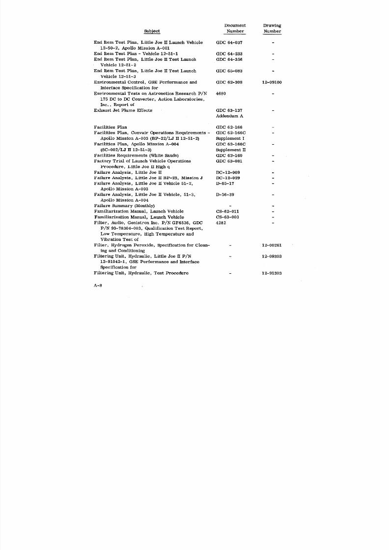
8/6/2019 Little Joe II Test Launch Vehicle NASA Project Apollo. Volume 1 Management
http://slidepdf.com/reader/full/little-joe-ii-test-launch-vehicle-nasa-project-apollo-volume-1-management 128/157
Document Drawing
_bject Number Number
End Item Test Plan, Little Joe II Launch Vehicle GDC 64-037
12-50-2, Apollo Mission A-001
End Item Test Plan - Vehicle 12-51-1 GDC 64-233 -
End Item Test Plan, Little Joe H Test Launch GDC 64-356 -
Vehicle 12-51-2
End Item Test Plan, Little Joe H Test Launch GDC 65-083 -
Vehicle 12-51-3
Environmental Control, GSE Performance and GDC 62-308 12-09100
Interface Specification for
Environmental Tests on Astronetics Research P/N 4680
175 DC to DC Converter, Action Laboratories,
Inc., Report of
Exhaust Jet Plume Effects GDC 63-137 -
Addendum A
Facilities Plan GDC 62-166 -
Facilities Plan, Convair Operations Requirements - GDC 62-166C
Apollo Mission A-003 (BP-22/LJ H 12-51-2) Supplement I
Facilities Plan, Apollo Mission A-004 GDC 62-166C -
(SC-002/LJ H 12-51-3) Supplement II
Facilities Requirements (White Sands) GDC 62-160 -
Factory Trial of Launch Vehicle Operations GDC 63-081 -
Procedure, Little Joe H High q
Failure Analysis, Little Joe II DC-12-009 -
Failure Analysis, Little Joe H BP-23, Mission J DC-12-029
Failure Analysis, Little Joe H Vehicle 51-2, D-65-17 -
Apollo Mission .%-003
Failure Analysis, Little Joe H Vehicle, 51-3, D-56-39 -
Apollo Mission A-004
Failure Summary (Monthly) - -
Familiarization Manual, Launch Vehicle CS-62-011 -
Familiarization Manual, Launch Vehicle CS-63-003 -
Filter, Audio, Genistron Inc. P/N GF6536, GDC 4282
P/N 93-78304-003, Qualification Test Report,
Low Temperature, High Temperature andVibration Test of
Filter, Hydrogen Peroxide, Specification for Clean- - 12-00261
ing and Conditioning
Filtering Unit, Hydraulic, Little Joe II P/N - 12-09303
12-91042-1, GSE Performance and Interface
Specification for
Filtering Unit, Hydraulic, Test Procedure - 12-91303
A-8

8/6/2019 Little Joe II Test Launch Vehicle NASA Project Apollo. Volume 1 Management
http://slidepdf.com/reader/full/little-joe-ii-test-launch-vehicle-nasa-project-apollo-volume-1-management 129/157
Document Drawing
Sub]'ect Number Number
Financial Management Report (Monthly) NASA Form 533 -
Fin and Elevon Assembly, Little Joe H, Special 12-4714
Vibration Test Procedure for
Fin, Attitude Control, Little Joe II, Results of GDC 64-023 -
Ground Vibration and Associated Stiffness Test
Fin Bolt Installation/Removal Tools, GSE Per- - 12-09109
formance and Interface Specification for
Fin Flutter Analysis, Little Joe H Attitude Control, DF-12-120
Using Ground Vibration Test Modes
Fin Structural Response Test, Little Joe H, Evalu- 12A4714
ation Test Report
Fin Slings, GSE Performance and Interface Speci- GDC 62-311 12-09103
fication for
Fin Warpage, Effects of, on the Trajectory of Little DC-12-007
Joe II QTV Shot
Finish Specification, Little Joe II - 12-00004
Fixed Fin Flutter Analysis DF-12-102 -
Fixed Fin (Cantilevered) Little Joe H/Apollo, Ground GDC 63-055
Vibration Test Results
Flight Flutter Instrumentation for Little Joe II DF-12-110 -
Qualification Test Vehicle, Status Report
Flight Flutter Test Instrumentation (Required) DF-12-105 -
for Little Joe II Qualification Test Vehicle
Flight Report, Launch Vehicle, NASA Project GDC 63-193Apollo, Little Joe II QTV - Model Version
Vehicle 12-50-1
Flight Simulation, Little Joe II Vehicle 51-2 D-65-27 -
Forebody Mating Stand, GSE Performance and GDC 62-212 12-09104
Interface Specification for
Free-Floating Control Surface Analysis, Little D-65- 28
Joe II
Fuel Tank Assembly, P/N 892586, Vibration Test TP-325
Procedure for (Walter Kidde Co.)
Fuel Tank Assembly, P/N 892586, Vibration Test R-1636
Report (Kidde Aerospace Division)
General Performance Capabilities GDC 62-349 -
Ground Air Conditioning, Little Joe H T-12-10 -
Ground Service Supply Hoses, GSE Performance - 12-09119
and Interface Specification for
Guidance Accuracy Study of Little Joe II Vehicle DC-12-005
A-9

8/6/2019 Little Joe II Test Launch Vehicle NASA Project Apollo. Volume 1 Management
http://slidepdf.com/reader/full/little-joe-ii-test-launch-vehicle-nasa-project-apollo-volume-1-management 130/157
Document Drawing
Number Number
Gulton Battery Power Pack 24V0.180P, Little Joe H, GDC 64-350
Qualification Test Report for
Hardware List, Little Joe II Test Launch Vehicle GDC 62-170
Hardware Utilization List - 12-50-1 GDC 63-149
Hardware Utilization List- 12-50-2 GDC 64-040
Hardware Utilization List - Vehicle 12-51-1 GDC 64-237
Hardware Utilization List - Vehicle 12-51-2 GDC 65-007
Hardware Utilization List - Vehicle 12-51-3 GDC 65-164 -
Hose Adapter, Kit, Little Joe H P/N 12-91026 12-09280
Hose Kit, Bladder Leak Test, GSE Performance 12-09288
and Interface Specification for
Hose Kit - High Pressure Nitrogen, Little Joe H - 12-09265
P/N 12-91040, GSE Performance and InterfaceSpecification for
Hose Set, Extension, Hydraulic Cart, GSE Per- - 12-09281
formance and Interface Specification for
Hose Set, Extension, Hydrogen Peroxide, GSE - 12-09282
Performance and Interface Specification for
Hose Set, Extension, Pneumatic, GSE Performance - 12-09283
and Interface Specification for
Hydraulic Actuator Assembly and Components, A PM-12-2251
History of the Vibration Testing Performed on
Hydraulic Servocylinder, Aerodynamic Attitude GDC 64-309 -
Control, GDC P/N 12-40100-850, Qualifica-
tion Test Procedure for
Hydraulie Servocylinder, Aerodynamic Attitude GDC 64-347 -
Control System, Little Joe H, Qualification
Test Report on
Hydraulic Servoeylinder, Aerodynamic Attitude GDC 65-171 -
Control, GDC Part No. 12-40100-805, Special
Qualification Test Procedure for
Hydraulic Servocylinder, Little Joe H Aerodynamic GDC 65-200
Attitude Control System, GDC Part No. 12-
40100-805, Qualification Test Report forHydraulic Subsystem in the Little Joe H, Vibration DF-12-118
Qualification of
Hydraulic System, Attitude Control, Little Joe H, GDC 64-193
Vibration Qualification Program for
Hydraulic System Filtration Study, Little Joe II GDC 65-162 -
Attitude Control, Report of
A-10
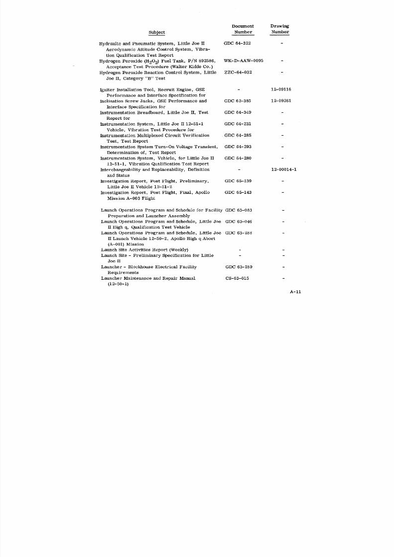
8/6/2019 Little Joe II Test Launch Vehicle NASA Project Apollo. Volume 1 Management
http://slidepdf.com/reader/full/little-joe-ii-test-launch-vehicle-nasa-project-apollo-volume-1-management 131/157
Document Drawing
Subject Number Number
Hydraulic and Pneumatic System, Little Joe II GDC 64-322 -
Aerodynamic Attitude Control System, Vibra-
tion Qualification Test Report
Hydrogen Peroxide (H202) Fuel Tank, P/N 892586, WK-D-AAW-0095
Acceptance Test Procedure (Walter Kidde Co.)
Hydrogen Peroxide Reaction Control System, Little ZZC-64-032
Joe II, Category "B" Test
Igniter Installation Tool, Recruit Engine, GSE - 12-09116
Performance and Interface Specification for
Inclination Screw Jacks, GSE Performance and GDC 62-385 12-09261
Interface Specification for
Instrumentation Breadboard, Little Joe H, Test GDC 64-349
Report forInstrumentation System, Little Joe H 12-51-1 GDC 64-231 -
Vehicle, Vibration Test Procedure for
Instrumentation Multiplexed Circuit Verification GDC 64-285
Test, Test Report
Instrumentation System Turn-On Voltage Transient, GDC 64-293
Determination of, Test Report
Instrumentation System, Vehicle, for Little Joe H GDC 64-280
12-51-1, Vibration Qualification Test Report
Interchangeability and Replaceability, Definition - 12-00014-1and Status
Investigation Report, Post Flight, Preliminary, GDC 65-139 -Little Joe H Vehicle 12-51-2
Investigation Report, Post Flight, Final, Apollo GDC 65-143
Mission A-003 Flight
Launch Operations Program and Schedule for Facility GDC 63-083
Preparation and Launcher Assembly
Launch Operations Program and Schedule, Little Joe GDC 63-046
H High q, Qualification Test Vehicle
Launch Operations Program and Schedule, Little Joe GDC 63-288
H Launch Vehicle 12-50-2, Apollo High q Abort
(A-001} Mission
Launch Site Activities Report (Weekly) - -
Launch Site - Preliminary Specification for Little - -
Joe II
Launcher- Blockhouse Electrical Facility GDC 63-289 -
Requirements
Launcher Maintenance and Repair Manual CS-63-015 -
(12-50-1)
A-11

8/6/2019 Little Joe II Test Launch Vehicle NASA Project Apollo. Volume 1 Management
http://slidepdf.com/reader/full/little-joe-ii-test-launch-vehicle-nasa-project-apollo-volume-1-management 132/157
Document Drawing
_bject Number Number
Launcher Maintenance and Repair Manual, Launch CS-63-039
Vehicle 12-50-2
Launcher Maintenance and Repair Manual, Launch CS-64-015
Vehicle 12-51-1
•Launcher Maintenance and Repair Manual, Launch CS-65-007
Vehicle 12-51-2
Launcher Maintenance and Repair Manual, Launch CS-65-007A
Vehicle 12-51-3
Launcher Mast, 12-95203, Proof and Operational SL-62-065
Test
Launcher Position Control, GSE Performance and GDC 62-220 12-09112
Interface Specification for
Load Bar, Three Recruit Installation, P/N 12- - 12-09294
91036-1, GSE Performance and Interface Speci-fication for
Limitations, Launch Operations, Little Joe H GDC 64-307 -
Logic and Control Amplifier, Attitude Reference GDC 65-210
Subsystem of the Attitude Control System
Qualification Test for
Logic and Control Amplifier, Attitude Reference GDC 65-219
Subsystem of the Attitude Control System,
Qualification Test Report for
Logic and Control Amplifier, 12-03101-1, Serial GDC 66-501
No. S-N3, Failure Analysis of
Logic and Control Amplifier 12-03101-3 Modified, GDC 66-046
Attitude Reference Subsystem of the Attitude
Control System, Qualification Test Report for
Logic and Control Unit Test, Little Joe II, DC-12-017 -
Preliminary Analysis
Maintenance Plan GDC 62-281
Manifold and Burst Disc Assembly, P/N 842396, TP-326
Vibration Test Procedure for (Walter Kidde
Co.)
Manifold and Burst Disc Assembly, P/N 842396, R-1616
Vibration Test Report (Walter Kidde Co. )
Manifold, Hydraulic Test, Little Joe II P/N 12-09302
12-91041-1, GSE Performance and Interface
Specification for
Manufacturing Plan GDC 62-205 -
Materials Evaluation for Base Thermal Protection RT-62-040
Materials Evaluation for Launcher Thermal RT-62-039 -
Protection
A-12
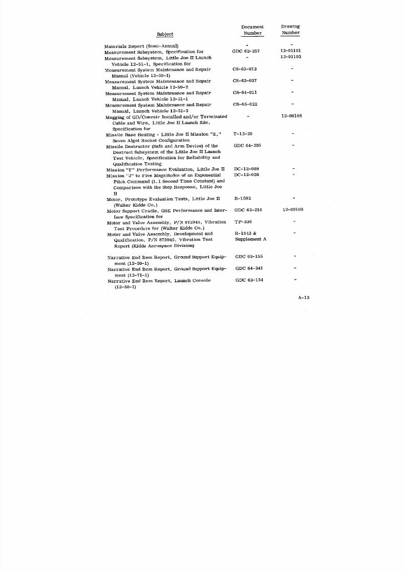
8/6/2019 Little Joe II Test Launch Vehicle NASA Project Apollo. Volume 1 Management
http://slidepdf.com/reader/full/little-joe-ii-test-launch-vehicle-nasa-project-apollo-volume-1-management 133/157
Document Drawing
Subject Number Number
Materials Report (Semi-Annual) - -
Measurement Subsystem, Specification for GDC 62-257 12-01101
Measurement Subsystem, Little Joe II Launch - 12-01103Vehicle 12-51-1, Specification for
Measurement System Maintenance and Repair CS-63-013 -
Manual (Vehicle 12-50-1)
Measurement System Maintenance and Repair CS-63-037
Manual, Launch Vehicle 12-50-2
Measurement System Maintenance and Repair CS-64-011 -
Manual, Launch Vehicle 12-51-1
Measurement System Maintenance and Repair CS-65-022 -
Manual, Launch Vehicle 12'51-3
Megging of GD/Convair Installed and/or Terminated - 12-06108
Cable and Wire, Little Joe II Launch Site,
Specification for
Missile Base Heating - LittleJoe IIMission "E," T-12-20
Seven Algol Rocket Configuration
Missile Destructor (Safeand Arm Device) ofthe GDC 64-295
DestructSubsystem oftheLittleJoe IILaunch
Test Vehicle,SpecificationorReliabilitynd
Qualificationesting
Mission "F" Performance Evaluation,LittleJoe II DC-12-008
Mission "J" to Five Magnitudes of an Exponential DC-12-026
Pitch Command (1.1 Second Time Constant) andComparison with the Step Response, Little Joe
II
Motor, Prototype Evaluation Tests, Little Joe II R-1592
(Walter Kidde Co.)
Motor Support Cradle, GSE Performance and Inter- GDC 62-216 12-09108
face Specification for
Motor and Valve Assembly, P/N 873945, Vibration TP-330
Test Procedure for (Walter Kidde Co.)
Motor and Valve Assembly, Development and R-1643 & -
Qualification, P/N 873945, Vibration Test Supplement A
Report (Kidde Aerospace Division)
Narrative End Item Report, Ground Support Equip- GDC 63-155
ment (12-50-1)
Narrative End Item Report, Ground Support Equip- GDC 64-241
merit (12-71-1)
Narrative End Item Report, Launch Console GDC 63-154
(12-50-1)
A-13
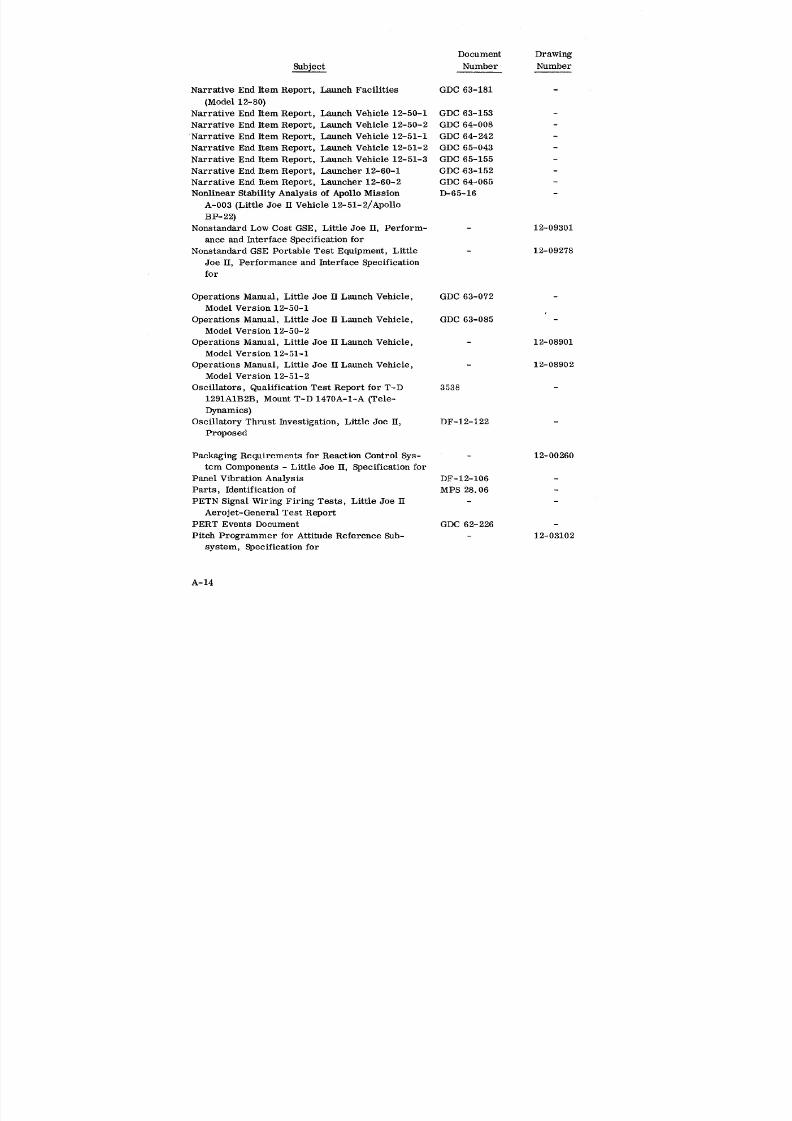
8/6/2019 Little Joe II Test Launch Vehicle NASA Project Apollo. Volume 1 Management
http://slidepdf.com/reader/full/little-joe-ii-test-launch-vehicle-nasa-project-apollo-volume-1-management 134/157
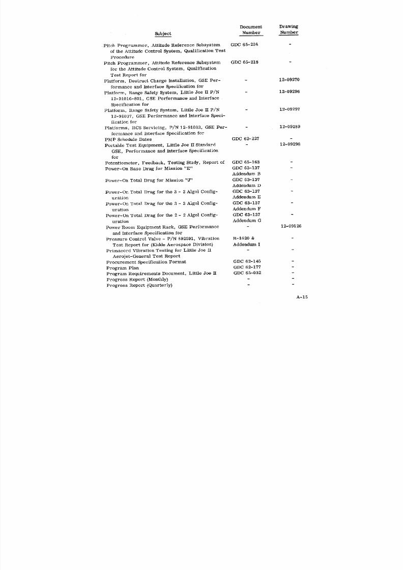
8/6/2019 Little Joe II Test Launch Vehicle NASA Project Apollo. Volume 1 Management
http://slidepdf.com/reader/full/little-joe-ii-test-launch-vehicle-nasa-project-apollo-volume-1-management 135/157
Document Drawing
Subject Number Number
Pitch Programmer, Attitude Reference Subsystem GDC 65-208
of the Attitude Control System, Qualification Test
Procedure
Pitch Programmer, Attitude Reference Subsystem GDC 65-218
for the Attitude Control System, Qualification
Test Report for
Platform, Destruct Charge Installation, GSE Per- - 12-09270
formance and Interface Specification for
Platform, Range Safety System, Little Joe II P/N 12-09296
12-91016-801, GSE Performance and Interface
Specification for
Platform, Range Safety System, Little Joe II P/N - 12-09297
12-91037, GSE Performance and Interface Speci-
fication for
Platforms, RCS Servicing, P/N 12-91033, GSE Per- - 12-09289
formance and Interface Specification for
PMP Schedule Dates GDC 62-227 -
Portable Test Equipment, Little Joe H Standard - 12-09298
GSE, Performance and Interface Specification
for
Potentiometer, Feedback, Testing Study, Report of GDC 65-163
Power-On Base Drag for Mission "E" GDC 63-137Addendum B
Power-On Total Drag for Mission "J" GDC 63-137 -Addendum D
Power-On Total Drag for the 3 - 2 Algol Config- GDC 63-137
uration Addendum E
Power-On Total Drag for the 3 - 3 Algol Config- GDC 63-137
uration Addendum F
Power-On Total Drag for the 2 - 2 Algol Config- GDC 63-137
uration Addendum G
Power Room Equipment Rack, GSE Performance - 12-09126
and Interface Specification for
Pressure Control Valve - P/N 892591, Vibration R-1620 &
Test Report for (Kidde Aerospace Division} Addendum I
Primacord Vibration Testing for Little Joe II - -
Aerojet-General Test Report
Procurement Specification Format GDC 62-145 -
Program Plan GDC 62-177 -
Program Requirements Document, Little Joe 11 GDC 65-032 -
Progress Report (Monthly) - -
Progress Report (Quarterly} - -
A-15
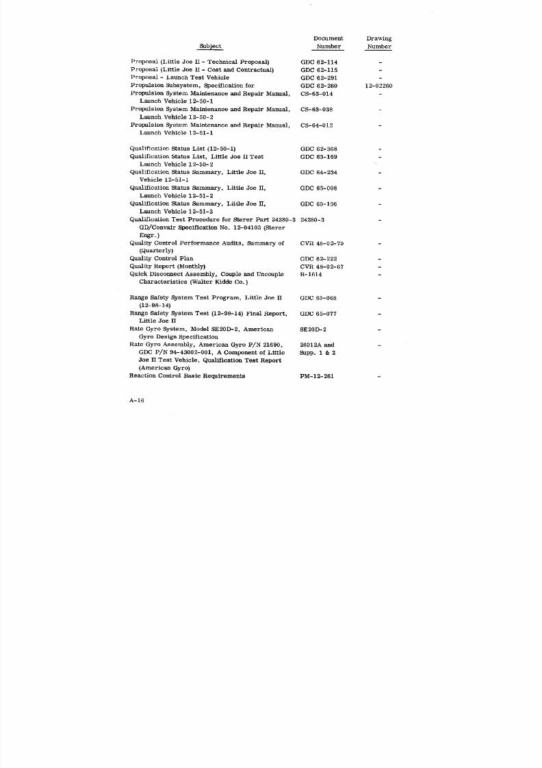
8/6/2019 Little Joe II Test Launch Vehicle NASA Project Apollo. Volume 1 Management
http://slidepdf.com/reader/full/little-joe-ii-test-launch-vehicle-nasa-project-apollo-volume-1-management 136/157
Document Drawing
Subject Number Number
Proposal (Little Joe II- Technical Proposal) GDC 62-114 -
Proposal (Little Joe II - Cost and Contractual) GDC 62-115 -
Proposal - Launch Test Vehicle GDC 62-291 -
Propulsion Subsystem, Specification for GDC 62-260 12-02260
Propulsion System Maintenance and Repair Manual, CS-63-014
Launch Vehicle 12-50-1
Propulsion System Maintenance and Repair Manual, CS-63-038
Launch Vehicle 12-50-2
Propulsion System Maintenance and Repair Manual, CS-64-012
Launch Vehicle 12-51-1
Qualification Status List (12-50-1) GDC 62-368 -
Qualification Status List, Little Joe II Test GDC 63-169 -
Launch Vehicle 12-50-2
Qualification Status Summary, Little Joe II, GDC 64-234 -
Vehicle 12-51-1
Qualification Status Summary, Little Joe H, GDC 65-008 -
Launch Vehicle 12-51-2
Qualification Status Summary, Little Joe H, GDC 65-156 -
Launch Vehicle 12-51-3
Qualification Test Procedure for Sterer Part 24280-3 24280-3
GD/Convair Specification No. 12-04103 (Sterer
Engr.)
Quality Control Performance Audits, Summary of CVR 48-02-70(Quarterly)
Quality Control plan GDC 62-222
Quality Report (Monthly) CVR 48-02-67
Quick Disconnect Assembly, Couple and Uncouple R-1614
Characteristics (Walter Kidde Co. )
Range Safety System Test Program, Little Joe II GDC 65-068
(12-98-14)
Range Safety System Test (12-98-14) Final Report, GDC 65-077
Little Joe H
Rate Gyro System, Model SE20D-2, American SE20D-2
Gyro Design Specification
Rate Gyro Assembly, American Gyro P/N 21690, 26012_ and
GDC P/N 94-43002-001, A Component of Little Supp. 1 & 2
Joe II Test Vehicle, Qualification Test Report
(American Gyro}
Reaction Control Basic Requirements PM-12-261 -
A-16

8/6/2019 Little Joe II Test Launch Vehicle NASA Project Apollo. Volume 1 Management
http://slidepdf.com/reader/full/little-joe-ii-test-launch-vehicle-nasa-project-apollo-volume-1-management 137/157
Document Drawing
Subject Number Number
Reaction Control - Hydrogen Peroxide System Study - 12-02601
Reaction Control Jet-Induced Aerodynamic Forces on AD-LJ-005
Little Joe II Stability and Control Character-
istics, Effect of
Reaction Control Module System Assembly Pro- 151238
cedure, Tank Installation, P/N 892631, 892613
(Walter Kidde Co. )
Reaction Control Motor, Effects of On/Off Delay DC-12-016
Time on Stability and Control of Little Joe II
Reaction Control - Solid Propellant System Study 12-02600
Reaction Control Subsystem, Little Joe II Relia- R-1645
bility Testing, Static Firing Tests (Kidde Rev. A
Aerospace Div. )
Reaction Control System, Little Joe II P/N 892630, WK-D-AAW-0107
Acceptance Test Procedure (Walter Kidde Co.)
Reaction Control System (892630) Little Joe II, 151736
Acceptance Test Procedure (Walter Kidde Co.)
Reaction Control System, Little Joe II, Component R-1591
Qualification Support Data (Walter Kidde Co.)
Reaction Control System for Launch Stabilization of D-65-21
Little Joe II Vehicle 12-51-2 on Apollo Mission
A-003, Effectiveness of
Reaction Control System Malfunctions on Little Joe DC-12-025
II Mission J, (NASA A-002) Effect ofReaction Control Systems (Module), P/N 892631 and TP-336
892613, Vibration Test Procedure for (Walter
Kidde Co. )
Reaction Control System Monopropellant Module, 12-02603
Specification for
Reaction Control System Qualification Test Results, R-1694
Bibliography and Summary of (Kidde Aerospace
Div. )
Reaction Control System Study GDC 62-247 -
Reaction Control System, P/N 892630, Little Joe H, R-1680
Vibration Test Report (Kidde Aerospace Division) Rev. A
Receiver, AN/DRW-ll UHF-FM, Qualification Test PM-12-1339
Plan for
Receiver, AN/DRW-ll, Qualification Test Report GDC 64-120
for
Receiver, AN/DRW-11 (P/N 12-32044-1) for use in GDC 64-339
Little Joe H Launch Vehicle 12-51-1 and on,
Qualification Test Report for
A-17

8/6/2019 Little Joe II Test Launch Vehicle NASA Project Apollo. Volume 1 Management
http://slidepdf.com/reader/full/little-joe-ii-test-launch-vehicle-nasa-project-apollo-volume-1-management 138/157
Document Drawing
_bject Number Number
Recovery Identification of Vehicle 12-50-2 GDC 64-077 -
Recovery Identification of Vehicle 12-51-1 GDC 64-243 -
Recovery Identification of Little Joe II Vehicle GDC 65-035 -
12-51-2 (Component Descriptions)
Recovery Identification Manual, Vehicle 12-51-3 GDC 65-123
RF Command Subsystem, Little Joe II Launch - 12-03270
Vehicle, Specification for
RF Command System Maintenance and Repair CS-64-010 -
Manual, Vehicle 12-51-1
RF Noise Filter, Part No. GF6099 (Genistron} 5632
Vibration Testing on (Rototest Laboratories)
Reliability Assessment Report, Mission A-002, - -
Little Joe H Vehicle 12-51-1
Reliability Assessment Report, Post Launch Relia- - -bility Summary, Little Joe II Vehicle 12-51-1,
Addendum I
Reliability Assessment Report, Little Joe II, Apollo GDC 65-109
Mission A-003 (12-51-2)
Reliability Assessment Report, Post Launch Relia- GDC 65-109
bility Summary, Apollo Mission A-003 (12-51-2} Addendum I
Reliability Assessment Report, Little Joe II Apollo GDC 65-222
Mission A-004 (12-51-3}
Reliability Assessment Report, Post Launch Relia- GDC 65-222
bility Summary, Little Joe H Vehicle 12-51-3 Addendum I
Reliability Plan (Part 1) GDC 62-168 -
Reliability Plan Part II, Reliability Test Plan GDC 62-204
Reliability Program Plan (NPC 250-1) GDC 64-119 -
Reliability Report, Little Joe H (Walter Kidde Co.) R-1586
Reliability Status Report (Quarterly)
Reliability Summary (Weekly)
Reliability Testing - Static Firing Procedure for TP-332
Reaction Control System Module - P/N 892630
(Walter Kidde Co. )
Relief Valve Assembly, P/N 873948, Vibration Test R-1617 &
Report (Walter Kidde Co. }Requirements for Work and Resources (RFWAR} at GDC 62-160
White Sands Missile Range
Reservoir, Cylinder, 400 cu. in., 500 PDI, P/N 63-106
23711537, Qualification Test Report for (Taveo}
Rigging Fixture, BP-22 and AFR-02 Umbilical (P/N - 12-09295
12-91035-1) GSE Performance and Interface
Specification for
A-18
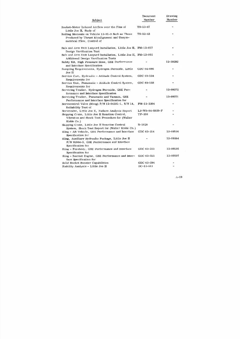
8/6/2019 Little Joe II Test Launch Vehicle NASA Project Apollo. Volume 1 Management
http://slidepdf.com/reader/full/little-joe-ii-test-launch-vehicle-nasa-project-apollo-volume-1-management 139/157
Document Drawing
Subject Number Number
Rocket-Motor Induced Airflow over the Fins of TS-12-47
Little Joe H, Study of
Rolling Moments on Vehicle 12-51-3 Such as Those TS-12-43
Produced by Thrust Misalignment and Unsym-
metrical Flow, Control of
Safe and Arm Unit Lanyard Installation, Little Joe II, PM-12-817
Design Verification Test
Safe and Arm Unit Lanyard Installation, Little Joe II, PM-12-892
Additional Design Verification Tests
Safety Kit, High Pressure Hose, GSE Performance - 12-09292
and Interface Specification
Sampling Requirements, Hydrogen Peroxide, Little GDC 64-086
Joe II
Service Cart, Hydraulic - Attitude Control System, GDC 63-134
Requirements for
Service Unit, Pneumatic - Attitude Control System, GDC 63-133
Requirements for
Servicing Trailer, Hydrogen Peroxide, GSE Per- 12-09272
formance and Interface Specification
Servicing Trailer, Pneumatic and Vacuum, GSE 12-09271
Performance and Interface Specification for
Servocontrol Valve (Moog) P/N 12-04101-1, S/N 14, PM-12-2264
Reliability Test ofServovalve, Little Joe II, Failure Analysis Report LJ-WS-04-5029-F -
Shipping Crate, Little Joe II Reaction Control, TP-338
Vibration and Shock Test Procedure for (Walter
Kidde Co. )
Shipping Crate, Little Joe II Reaction Control R-1628
System, Shock Test Report for (Walter Kidde Co.)
Sling - Aft Vehicle, GSE Performance and Interface GDC 62-214 12-09106
Specification for
Sling, Auxiliary Hydraulic Package, Little Joe H - 12-09264
P/N 91004-3, GSE Performance and Interface
Specification for
Sling - Forebody, GSE Performance and Interface GDC 62-213 12-09105
Specification for
Sling - Recruit Engine, GSE Performance and Inter- GDC 62-215 12-09107
face Specification for
Solid Rocket Booster Capabilities GDC 62-294 -
Stability Analysis - Little Joe II DC-12-011 -
A-19

8/6/2019 Little Joe II Test Launch Vehicle NASA Project Apollo. Volume 1 Management
http://slidepdf.com/reader/full/little-joe-ii-test-launch-vehicle-nasa-project-apollo-volume-1-management 140/157
Document Drawing
Number Number
Stand, Reaction Control System Test, GSE Perform- - 12-09273
ance and Interface Specification for
Statement of Similarity Between Models 89G122 and -
89G26, (GDC P/N 12-02605-1) (Custom Components)
Statement of Work (NASA) GDC 62-361 -
Statement of Work (Convair) CPO 26-201-44 GDC 62-369 -
Static Inverter, 3 Phase, 500 VA, for use in the - 12-06103
Attitude Control Subsystem, Specificatio n for
Static Inverter, Type 39B64-3-A 175 VA, Final 645 &
Engineering Report of Tests Conducted on Supp. 1 & 2
(Bendix - Red Bank Division)
Storage Cradle and Pad, GSE Performance and GDC 62-209 12-09101
interface Specification for
Storage Unit, High Pressure Nitrogen, Little Joe - 12-09299H P/N 12-91039, GSE Performance and Inter-
face Specification for
Stress Analysis, Little Joe H Attitude Control R-1588
Mounting Rack (Walter Kidde Co. )
Stress Analysis of Little Joe H QTV Dummy Pay- GDC 63-040load Structure
Stress Analysis of Little Joe H Attitude Control GDC 63-037 -
Fins
Stress Analysis for Little Joe II Attitude Control GDC 63-037
Fins, Ballast Installation for Vehicle 12-51-3 Addendum I
Stress Analysis, Ballast Installation for Vehicle GDC 63-039
12-51-3 Addendum HI
Stress Analysis, Ground Handling Equipment, Little GDC 63-041
Joe II Launch Vehicle
Stress Analysis of Little Joe H Launcher GDC 63-038 -
Stress Analysis of Retract Mechanism and Mast GDC 63-038Extension for BP-22 and AFR-2 Addendum I
Stress Analysis, Little Joe II Launch Vehicle GDC 63-039 -
Stress Analysis, Hydraulic System No. 2, Attitude GDC 63-039Control
Stress Analysis - Vehicle Ballast Installations GDC 63-039 -Addendum H
Stress Analysis of Little Joe H Stabilizing Fins GDC 63-036 -
Structural Design and Loads Criteria GDC 62-278 -
Structural Suitability of Little Joe II for Apollo TS-12-50
Mission A-004 Test Point (Mission Q)
Support Arm Protection Kit, GSE Performance - 12-09117
and Interface Specification for
A-20
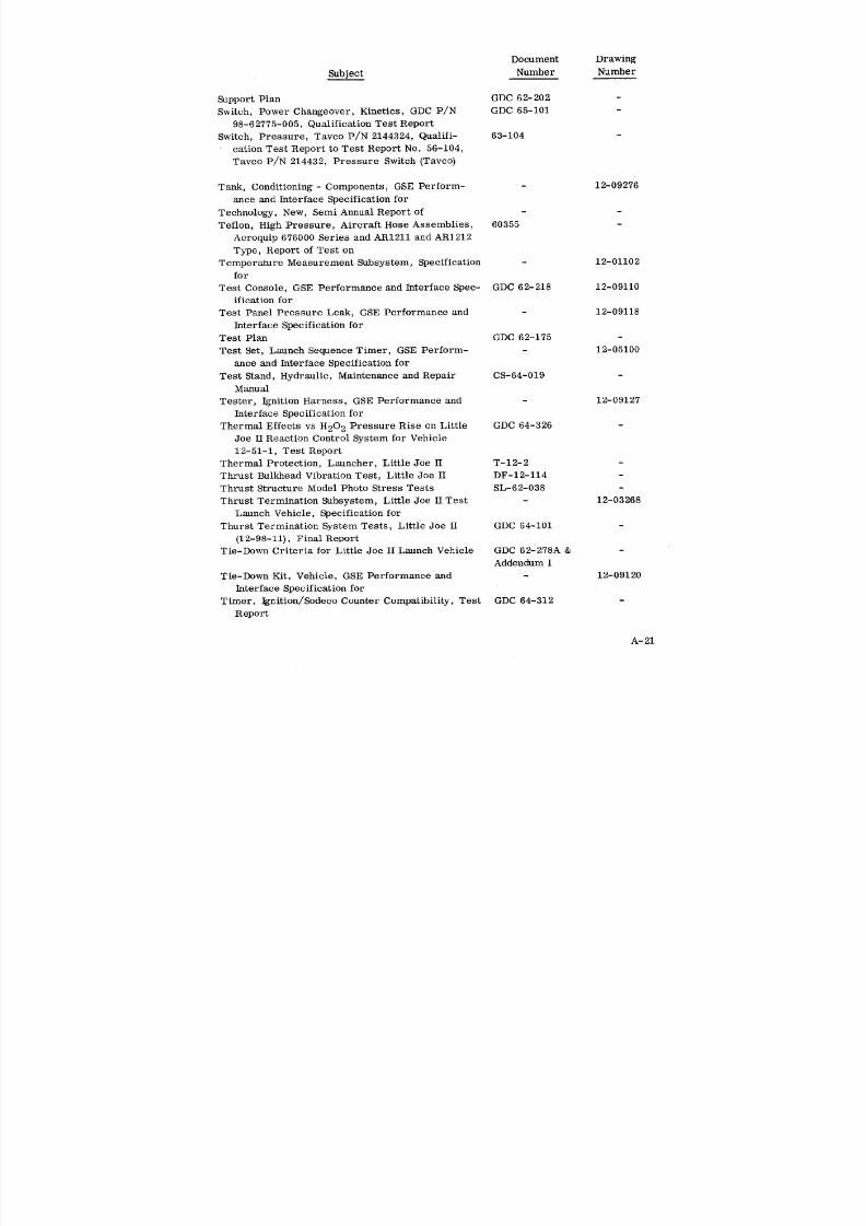
8/6/2019 Little Joe II Test Launch Vehicle NASA Project Apollo. Volume 1 Management
http://slidepdf.com/reader/full/little-joe-ii-test-launch-vehicle-nasa-project-apollo-volume-1-management 141/157
Document Drawing
Subject Number Number
Support Plan GDC 62-202 -
Switch, Power Changeover, Kinetics, GDC P/N GDC 65-101 -
98-62775-005, Qualification Test Report
Switch, Pressure, Tavco P/N 2144324, Qualifi- 63-104
cation Test Report to Test Report No. 56-104,
Tavco P/N 214432, Pressure Switch (Tavco)
Tank, Conditioning - Components, GSE Perform- - 12-09276
ance and Interface Specification for
Technology, New, Semi Annual Report of - -
Teflon, High Pressure, Aircraft Hose Assemblies, 60355
Aeroquip 676000 Series and AR1211 and AR1212
Type, Report of Test on
Temperature Measurement Subsystem, Specification - 12-01102
for
Test Console, GSE Performance and Interface Spec- GDC 62-218 12-09110
ification for
Test Panel Pressure Leak, GSE Performance and 12-09118
Interface Specification for
Test Plan GDC 62-175 -
Test Set, Launch Sequence Timer, GSE Perform- - 12-05100
ance and Interface Specification for
Test Stand, Hydraulic, Maintenance and Repair CS-64-019
ManualTester, Ignition Harness, GSE Performance and - 12-09127
Interface Specification for
Thermal Effects vs H20 2 Pressure Rise on Little GDC 64-326
Joe II Reaction Control System for Vehicle
12-51-1, Test Report
Thermal Protection, Launcher, Little Joe II T-12-2 -
Thrust Bulkhead Vibration Test, Little Joe II DF-12-114 -
Thrust Structure Model Photo Stress Tests SL-62-038 -
Thrust Termination Subsystem, Little Joe II Test - 12-03268
Launch Vehicle, Specification for
Thurst Termination System Tests, Little Joe II GDC 64-101 -
(12-98-11), Final Report
Tie-Down Criteria for Little Joe II Launch Vehicle GDC 62-278A &
Addendum I
Tie-Down Kit, Vehicle, GSE Performance and - 12-09120
Interface Specification for
Timer, Ignition/Sodeco Counter Compatibility, Test GDC 64-312
Report
A-21
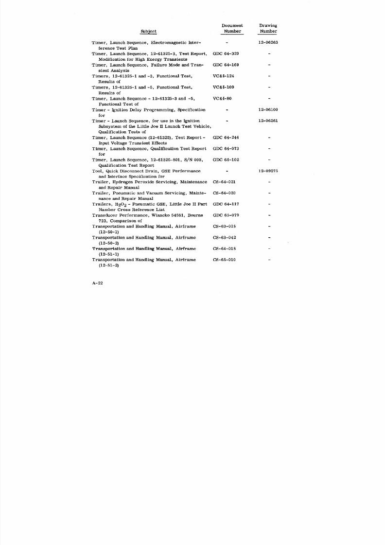
8/6/2019 Little Joe II Test Launch Vehicle NASA Project Apollo. Volume 1 Management
http://slidepdf.com/reader/full/little-joe-ii-test-launch-vehicle-nasa-project-apollo-volume-1-management 142/157
Document Drawing
Subject Number Number
Timer, Launch Sequence, Electromagnetic Inter- - 12-06263
ference Test Plan
Timer, Launch Sequence, 12-61325-3, Test Report, GDC 64-329
Modification for High Energy Transients
Timer, Launch Sequence, Failure Mode and Tran- GDC 64-169
sient Analysis
Timers, 12-61325-1 and -3, Functional Test, VC&I-124 -
Results of
Timers, 12-61325-1 and -5, Functional Test, VC&I-109 -
Results of
Timer, Launch Sequence - 12-61325-3 and -5, VC&I-80 -
Functional Test of
Timer - Ignition Delay Programming, Specification - 12-06100
forTimer - Launch Sequence, for use in the Ignition - 12-06261
Subsystem of the Little Joe n Launch Test Vehicle,
Qualification Tests of
Timer, Launch Sequence (12-61325), Test Report - GDC 64-244
Input Voltage Transient Effects
Timer, Launch Sequence, Qualification Test Report GDC 64-073for
Timer, Launch Sequence, 12-61325-801, S/N 003, GDC 65-102
Qualification Test Report
Tool, Quick Disconnect Drain, GSE Performance - 12-09275
and Interface Specification for
Trailer, Hydrogen Peroxide Servicing, Maintenance CS-64-021
and Repair Manual
Trailer, Pneumatic and Vacuum Servicing, Mainte- CS-64-020
nance and Repair Manual
Trailers, H20 2 - Pneumatic GSE, Little Joe II Part GDC 64-117Number Cross Reference List
Transducer Performance, Wiancko 54581, Bourns GDC 65-079
723, Comparison of
Transportation and Handling Manual, Airframe CS-6"3-018 -
(12-50-1)Transportation and Handling Manual, Airframe CS-63-042
(12-50-2)
Transportation and Handling Manual, Airframe CS-64-018
(12-51-1)
Transportation and Handling Manual, Airframe CS-65-010
(12-51-2)
A-22
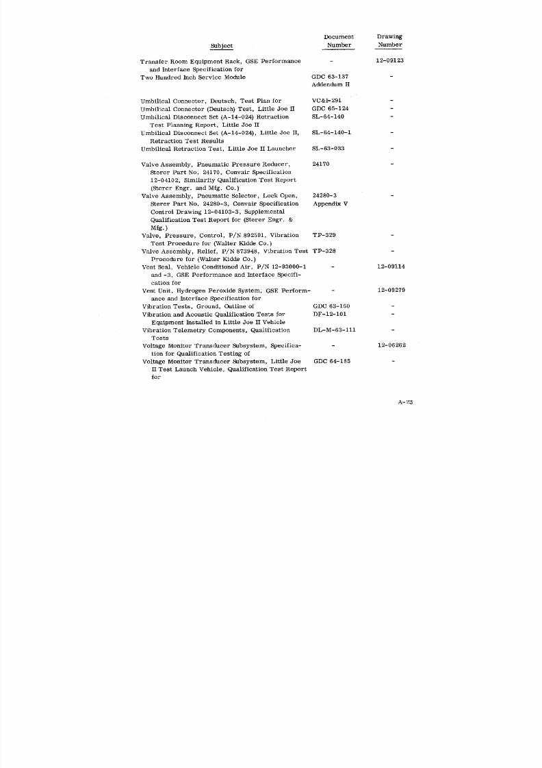
8/6/2019 Little Joe II Test Launch Vehicle NASA Project Apollo. Volume 1 Management
http://slidepdf.com/reader/full/little-joe-ii-test-launch-vehicle-nasa-project-apollo-volume-1-management 143/157
Document Drawing
Subject Number Number
Transfer Room Equipment Rack, GSE Performance - 12-09123
and Interface Specification for
Two Hundred Inch Service Module GDC 63-137 -
Addendum H
Umbilical Connector, Deutsch, Test Plan for VC&I-291 -
Umbilical Connector (Deutsch) Test, Little Joe H GDC 65-124
Umbilical Disconnect Set (A-14-024) Retraction SL-64-140
Test Planning Report, Little Joe II
Umbilical Disconnect Set (A-14-024), Little Joe II, SL-64-140-1
Retraction Test Results
Umbilical Retraction Test, Little Joe II Launcher SL-63-033
Valve Assembly, Pneumatic Pressure Reducer, 24170
Sterer Part No. 24170, Convair Specification
12-04102, Similarity Qualification Test Report
(Sterer Engr. and Mfg. Co.)
Valve Assembly, Pneumatic Selector, Lock Open, 24280-3
Sterer Part No. 24280-3, Convair Specification Appendix V
Control Drawing 12-04103-3, Supplemental
Qualification Test Report for (Sterer Engr. &
Mfg.)
Valve, Pressure, Control, P/N 892591, Vibration TP-329
Test Procedure for (Walter Kidde Co.)Valve Assembly, Relief, P/N 873948, Vibration Test TP-328
Procedure for (Walter Kidde Co.)
Vent Seal, Vehicle Conditioned Air, P/N 12-93000-1 - 12-09114
and -3, GSE Performance and Interface Specifi-
cation for
Vent Unit, Hydrogen Peroxide System, GSE Perform- - 12-09279
ance and Interface Specification for
Vibration Tests, Ground, Outline of GDC 63-150 -
Vibration and Acoustic Qualification Tests for DF-12-101 -
Equipment Installed in Little Joe II Vehicle
Vibration Telemetry Components, Qualification DL-M-63-111 -
Tests
Voltage Monitor Transducer Subsystem, Specifica- - 12-06262
tion for Qualification Testing of
Voltage Monitor Transducer Subsystem, Little Joe GDC 64-185
II Test Launch Vehicle, Qualification Test Report
for
A-23
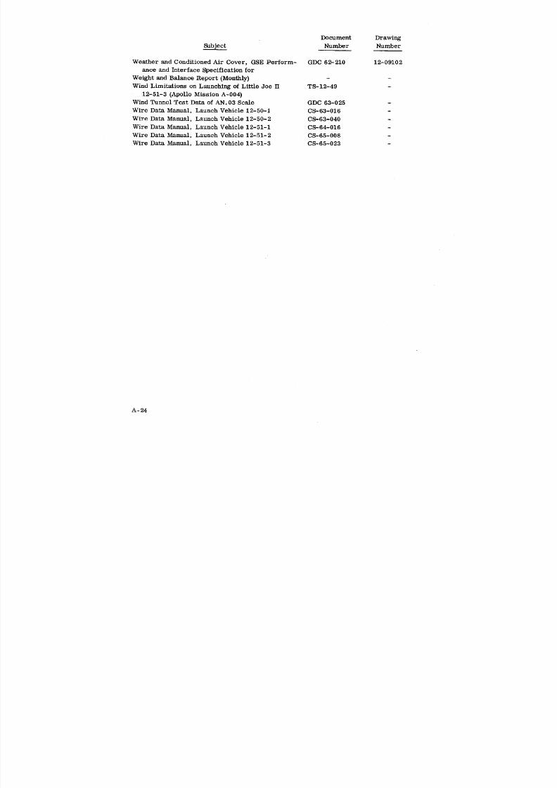
8/6/2019 Little Joe II Test Launch Vehicle NASA Project Apollo. Volume 1 Management
http://slidepdf.com/reader/full/little-joe-ii-test-launch-vehicle-nasa-project-apollo-volume-1-management 144/157
Document Drawing
Subject Number Number
Weather and Conditioned Air Cover, GSE Perform- GDC 62-210 12-09102
ante and Interface Specification for
Weight and Balance Report (Monthly) - -
Wind Limitations on Launching of Little Joe H TS-12-49 -
12-51-3 (Apollo Mission A-004)
Wind Tunnel Test Data of AN. 03 Scale GDC 63-025 -
Wire Data Manual, Launch Vehicle 12-50-1 CS-63-016 -
Wire Data Manual, Launch Vehicle 12-50-2 CS-63-040 -
Wire Data Manual, Launch Vehicle 12-51-1 CS-64-016 -
Wire Data Manual, Launch Vehicle 12-51-2 CS-65-008 -
Wire Data Manual, Launch Vehicle 12-51-3 CS-65-023 -
A-24
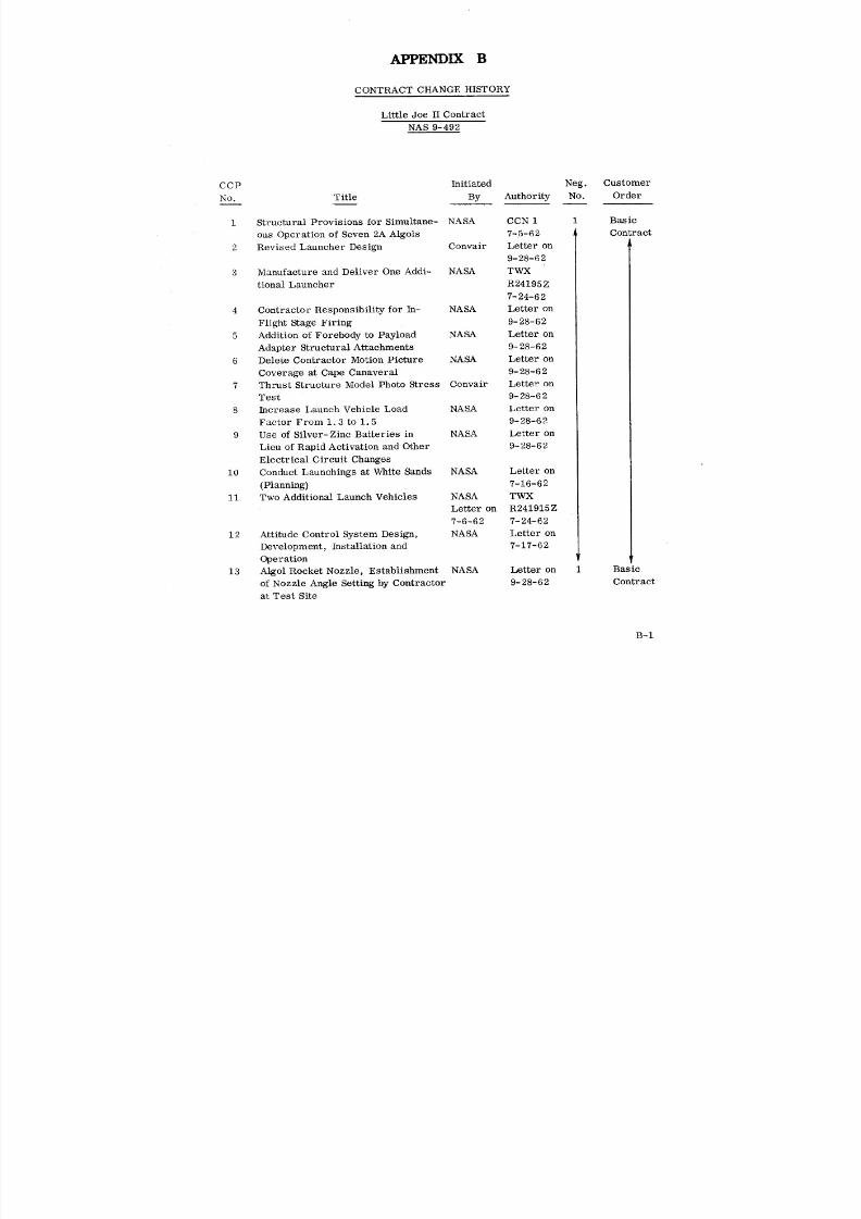
8/6/2019 Little Joe II Test Launch Vehicle NASA Project Apollo. Volume 1 Management
http://slidepdf.com/reader/full/little-joe-ii-test-launch-vehicle-nasa-project-apollo-volume-1-management 145/157
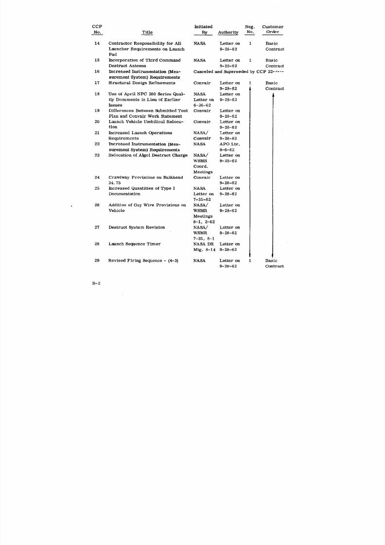
8/6/2019 Little Joe II Test Launch Vehicle NASA Project Apollo. Volume 1 Management
http://slidepdf.com/reader/full/little-joe-ii-test-launch-vehicle-nasa-project-apollo-volume-1-management 146/157
CCP Initiated Neg. Customer
No. Title By Authority No. Order
14 Contractor Responsibility for All NASA Letter on 1 Basic
Launcher Requirements on Launch 9- 28-62 Contract
Pad
15 Incorporation of Third Command NASA Letter on 1 Basic
Destruct Antenna 9- 28-62 Contract
16 Increased Instrumentation (Mea- Canceled and Superseded by CCP 22-----
surement System) Requirements
17 Structural Design Refinements Convair Letter on 1 Basic
9- 28-62 Contract
18 Use of April NPC 200 Series Qual- NASA Letter on
ity Documents in Lieu of Earlier Letter on 9-28-62
Issues 6-26-62
19 Differences Between Submitted Test Convair Letter on
Plan and Convair Work Statement 9-28-6220 Launch Vehicle Umbilical Reloca- Convair Letter on
tion 9- 28-62
21 Increased Launch Operations NASA/ Letter on
Requirements Convair 9-28-62
22 Increased Instrumentation (Mea- NASA APO Ltr.
surement System} Requirements 8-6-62
23 Relocation of Algol Destruct Charge NASA/ Letter on
WSMR 9-28-62
Coord.
Meetings24 Crawlway Provisions on Bulkhead Convair Letter on
34.75 9-28-62
25 Increased Quantities of Type I NASA Letter on
Documentation Letter on 9-28-62
7-31-62
26 Addition of Guy Wire Provisions on NASA/ Letter on
Vehicle WSMR 9-28-62
Meetings
8-1, 2-62
27 Destruct System Revision NASA/ Letter on
WSMR 9-28-62
7-31, 8-1
28 Launch Sequence Timer NASA DR Letter on
Mtg. 8-14 9-28-62
29 Revised Firing Sequence - (4-3) NASA Letter on Basic
9- 28-62 Contract
B-2

8/6/2019 Little Joe II Test Launch Vehicle NASA Project Apollo. Volume 1 Management
http://slidepdf.com/reader/full/little-joe-ii-test-launch-vehicle-nasa-project-apollo-volume-1-management 147/157
CC P Initiated Neg. Customer
No. Title By Authority No. Order
30 Revised Program Quantity and Schcd- NASA Letter on 1 Basic
ule (Revise schedule, reduce quan- APO Ltr. 9-28-62 Contract
tity of vehicles from 7 to 4 and re- 9-14-62
lated changes to procurement of NASA
attitude control system and manu- TWX on
facture of fixed fins). 9-25-62
31 Test Shot of LittleJoe IILaunch Disapproved .........................
Vehicle
32 Revised Payload Length NASA 1 Basic
TWX Contract
R031400 Z
10-62
33 AutopilotTest Installationn First Disapproved..........................
Vehicle
34 DeterminationofAcoustic and NASA PM-12- 1 Basic
Vibration- Algol Motors 258 Contract
35 Fin Loading Revision Convair 1 Basic
Contract
36 Blockhouse toTransfer/Power Room Disapproved..........................
Wiring - Installation of
37 Cancellation of NASA Attitude Con- NASA TWX 11-15 Basic
trol Breadboard R011800 Z Contract
11-1-62
38 Fixed Fin Ground VibrationTests NASA PM-12-
385
39 RevisionofLauncher Vehicle Sup- NASA PM-12-
port Arm 368
40 Launcher StructuralRevision - Convair PM-12-
Rocket Blast Protection 385
41 Additional Fin Flutter Analysis Convair PM-12-385
42 Ground Support Equipment Revisions Convair NASA Ltr.
Ref. CA
11-29-62
43 Omission of Instrumentation, Ve- NASA Verbal 1 Basic
hicles 2, 3 and 4 11-19 & Contract
11- 21
44 Vehicle Air Conditioning Revisions NASA NASA TWX 2 Amend 1
(Additional Inlet Door) 12-123
Rll154OZ
B-3
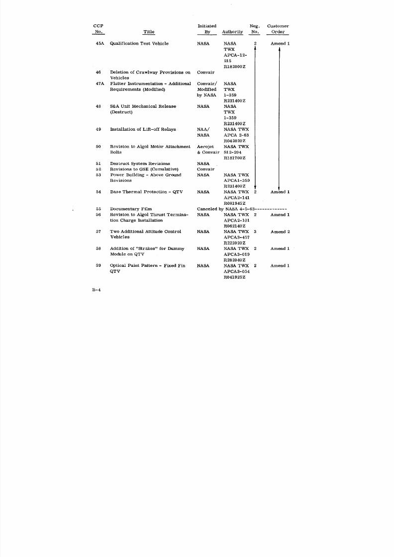
8/6/2019 Little Joe II Test Launch Vehicle NASA Project Apollo. Volume 1 Management
http://slidepdf.com/reader/full/little-joe-ii-test-launch-vehicle-nasa-project-apollo-volume-1-management 148/157
CCP Initiated Neg. Customer
No. Title By Authority No. Order
45A Qualification Test Vehicle NASA NASA 2 Amend 1
TWX
APCA-12-
215
R182000Z
46 Deletion of Crawlway Provisions on ConvairVehicles
47A Flutter Instrumentation - Additional Convair/ NASA
Requirements (Modified) Modified TWX
by NASA 1-359
R231400 Z
48 S&A Unit Mechanical Release NASA NASA
(Destruct) TWX
1-359R231400 Z
49 Installation of Lift-off Relays NAA/ NASA TWX
NASA APCA 2-63
R042020 Z
50 Revision to Algol Motor Attachment Aerojet NASA TWX
Bolts & Convair $12-204
R181700Z
51 Destruct System Revisions NASA
52 Revisions to GSE (Cumulative) Convair
53 Power Building - Above Ground NASA NASA TWXRevis ions APCA 1- 359
R231400 Z
54 Base Thermal Protection - QTV NASA NASA TWX 2 Am ad 1
APCA2-141
R081945 Z
55 Documentary Film Canceled by NASA 4-5-63 .............
56 Revision to Algol Thrust Termina- NASA NASA TWX 2 Amend 1
tion Charge Installation APCA2-101
R062140Z
57 Two Additional Attitude Control NASA NASA TWX 3 Amend 2
Vehicles APCA3-457R222020Z
58 Addition of "Strakes" for Dummy NASA NASA TWX 2 Amend 1
Module on QTV APCA3-019
R282040Z
59 Optical Paint Pattern - Fixed Fin NASA NASA TWX 2 Amend 1
QTV APCA3-054
R041925Z
B-4
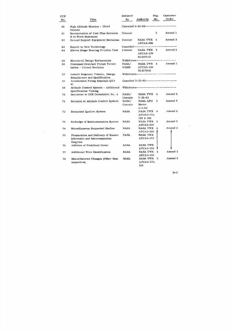
8/6/2019 Little Joe II Test Launch Vehicle NASA Project Apollo. Volume 1 Management
http://slidepdf.com/reader/full/little-joe-ii-test-launch-vehicle-nasa-project-apollo-volume-1-management 149/157
CCP Initiated Neg. Customer
No. Title By Authority No. Order
60 High Altitude Mission - Third Canceled 5-16-63 .....................
Vehicle
61 Incorporation of Test Plan Revision Convair 2 Amend 1
B in Work Statement
62 Ground Support Equipment Revisions Convair NASA TWX 4 Amend 3
APCA6-080
63 Report on New Technology Canceled .............................
64 Elevon Hinge Bearing Friction Test Convair NASA TWX 5 Amend 5APCA5-370
R142215Z
65 Structural Design Refinements Withdrawn ...........................
66 Command Destruct Thrust Termi- NASA/ NASA TWX 4 Amend 3
nation - Circuit Revision WSMR APCA5-310
R141700Z
67 Launch Sequence Timers, Design Withdrawn ...........................
Manufacture and Qualification
68 AcceleratedFiring ScheduleQTV Canceled 5-23-63.....................
#I
69 AttitudeControl System - Additional Withdrawn...........................
Qualificationesting
70 Revisionsto GSE Cumulative No. 4 NASA/ NASA TWX 4 Amend 3
Convair 7-26-63
71 Revision toAttitudeControlSystem NASA/ NASA APO 5 Amend 5
Convair Memo
4-4-63
72 Redundant Ignition System NASA NASA TWX 4 Amend 3
APCA5-173,
195 & 310
73 Redesign of Instrumentation System NASA NASA TWX 5 Amend 5APCA5-310
74 Miscellaneous Requested Studies NASA NASA TWX 4 Amend 3
APCA5-310
75 Preparation and Delivery of Master NASA NASA TWX
Schematic and Interconnection APCA5-173
Diagram
76 Addition of Umbilical Cover NASA NASA TWX
APCA5-310
77 Additional Wire Identification NASA NASA TWX 4 Amend 3
APCA5-310
78 Miscellaneous Changes (Other than NASA NASA TWX 5 Amend 5
inspection) APCA5-173,310
B-5

8/6/2019 Little Joe II Test Launch Vehicle NASA Project Apollo. Volume 1 Management
http://slidepdf.com/reader/full/little-joe-ii-test-launch-vehicle-nasa-project-apollo-volume-1-management 150/157
CCP Initiated Neg. Customer
No. Title By Authority No. Order
79 Reduction of QTV Data NASA APCAT 4 Amend 3
7-011. 225
80 Installation of NAA Pressure NASA APCA5-420
Bulkhead in 12-50-1 QTV
81 Installation of Dual Destruct NASA APCA6-082
System
82 Termination of NASA-Furnished NASA APCA6-061 4 Amend 3
Cables in Blockhouse and at Launch
Pad
83 Revisions to Operational Checkout NASA APCA5-310 5 Amend 5
Instructions
84 Installation of Radar Transponder NASA APCA6-083 4 Amend 3
Beacon System
85 Installation of Telemetering Pack- NASA APCA6-298 4 Amend 3age for Accelerometers and
Pressure Pickups in QTV
86 Additional Changes Resulting from NASA APCAT 5 Amend 5
NASA DEI of 10 June 1963 7-009.223
87 Modification of Recru{t Ignition NASA APCA6-060 4 Amend 3
System
88 Revisions to Ground Support NASA 4
Equipment - Cumulative No. 5
89 Breadboard Autopilot for NASA NASA APCAT 4 Amend 3
7-204
90 Modification of 12-51-1 Configura- NASA APCAT 4 Amend 3
tion 7-008. 222
91 Installation of Dual Destruct Sys- Withdrawn ..............................
tem for Attitude Control Vehicles
(Mod. 12-51)
92 Direct Distribution of Little Joe H Canceled - replaced by CCP 116 .........
Documentation
93 Additional Launch Operations Tasks Withdrawn ..............................
and Effect of Revised Launch
Schedules
94 Reschedule of Launcher #12-60-2 NASA NASA TWX 5 Amend 5
by NASA APCAT
6-199
95 Addition of Mercury Cell for NASA NASA TWX 5 Amend 5
Instrumented Reference Voltage APCAT
7-012o 226
B-6

8/6/2019 Little Joe II Test Launch Vehicle NASA Project Apollo. Volume 1 Management
http://slidepdf.com/reader/full/little-joe-ii-test-launch-vehicle-nasa-project-apollo-volume-1-management 151/157
CCP Initiated Neg. Customer
No. Title By Authority No. Order
96 RFI Testing - White Sands Missile NASA NASA and 5 Amend 5
Range Requirements PM-12-991
97 Incorporation of Reaction Control NASA NASA TWX
System into Breadboard Test 7-27-63
Program
98 Revised North American Aviation NASA NASA 5 Amend 5
Electrical Interface CCA No. 1
99 Compliance with Section 15 of NASA NASA 5
MSFC Drafting Manual dated CCA No. 4
5 February 1963
1O0 Acceptance Data Package NASA 6 Amend 8
i01 Implementation of MSFC-PROC- NASA NASA TWX 5 Amend 5
158B, "Uniform Requirements for APCA5-420
Soldering" APCA 6- 260102 Rewrite Field Operational Check- NASA/ NASA
out Instructions to Apollo Format WSMR CCA No. 9
103 Ignition System Revision - In NASA NASA TWX
Flight Staging APCA5-1735-195 &
5-310
104 Storage of Vehicle 12-50-2 at NASA NASA
GD/Convair CCA No. 4
105 Production Logic and Control Unit NASA NASA
and Pitch Programmer for NASA CCA No. 6Autopilot CCA No. 7
106 Contractor Furnished Batteries and Convair/ NASA 5 Amend 5
Commutators in Lieu of GFP for NASA CCA No. 5
Vehicle 12-51-1 Measurement CCA No. 6
Power
107 Thirty "G" Vibration Testing of Canceled - replaced by CCP107A ........
Reaction Control System
107A Thirty "G" Vibration Testing of NASA NASA 6 Amend 8
Reaction Control System CCA No. 2
108 Implementation of Specification NASA NASA
NSC-ASPO-C-3 CCA No. 6
109 Vibration Testing of Instrumenta- NASA NASA
tion and Autopilot Systems CCA No. 11
110 Provisioning for and Development NASA NASA 6 Amend 8
of Pitch Programmer CCA No. 4
CCA No. 5
B-7
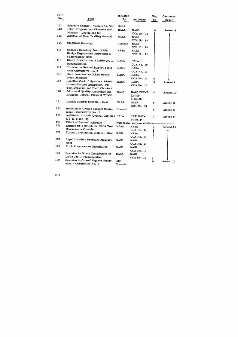
8/6/2019 Little Joe II Test Launch Vehicle NASA Project Apollo. Volume 1 Management
http://slidepdf.com/reader/full/little-joe-ii-test-launch-vehicle-nasa-project-apollo-volume-1-management 152/157
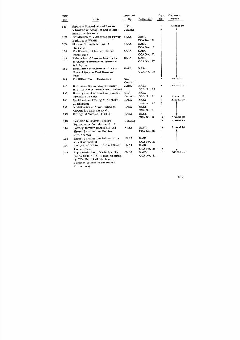
8/6/2019 Little Joe II Test Launch Vehicle NASA Project Apollo. Volume 1 Management
http://slidepdf.com/reader/full/little-joe-ii-test-launch-vehicle-nasa-project-apollo-volume-1-management 153/157
CCP Initiated Neg. Customer
No. Title ___By Authority No. Order
131 Separate Sinusoidal and Random GD/ 8 Amend 10
Vibration of Autopilot and Instru- Convair
mentation Systems
132 Installation of Visicorder in Power NASA NASA
Building at WSMR CCA No. 24
133 Storage of Launcher No. 2 NASA NASA
(12-60-2) CCA No. 17
134 Modification of Shaped Charge NASA NASA
Installation CCA No. 21
135 Relocation of Remote Monitoring NASA NASA
of Thrust Termination System S CCA No. 27
& A Squibs
136 Installation Requirement for Fin NASA NASA
Control System Test Stand at CCA No. 22WSMR
137 Facilities Plan - Revision of GD/ 8 Amend l0
Convair
138 Redundant De-Arming Circuitry NASA NASA 9 Amend 13
in Little Joe II Vehicle No. 12-50-2 CCA No. 29
139 Reassignment of Reaction Control GD/ NASA
Vibration Testing Convair CCA No. 2 9 Amend 13
140 Qualification Testing of AN/DRW- NASA NASA 8 Amend 10
11 Receiver CCA No. 25
141 Modification of Abort Initiation NASA NASA
Circuit for Mission A-001 CCA No. 35
142 Storage of Vehicle 12-50-3 NASA NASACCA No. 25 8 Amend 10
143 Revision to Ground Support Convair 9 Amend 13
Equipment - Cumulative No. 9
144 Battery Jumper Harnesses and NASA NASA 8 Amend 10
Thrust Termination Monitor CCA No. 34
Line Adapter
145 Thrust Termination Primaeord - NASA NASA
Vibration Test of CCA No. 33
146 Analysis of Vehicle 12-50-2 Post NASA NASA
Launch Data CCA No. 36
147 Implementation of NASA Specifi- NASA NASA 8 Am nd 10
cation MSC-ASPO-S-2 as Modified CCA No. 31
by CCA No. 31 (Solderless,
Crimped Splices of Electrical
Conductors)
B-9
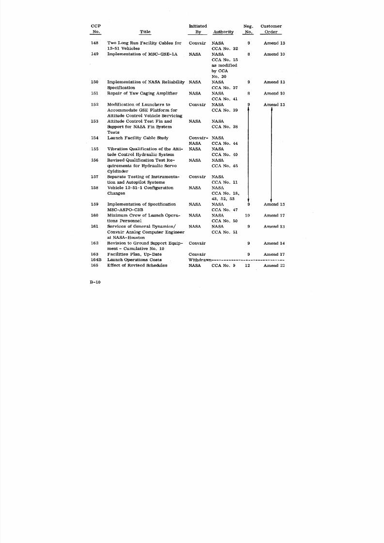
8/6/2019 Little Joe II Test Launch Vehicle NASA Project Apollo. Volume 1 Management
http://slidepdf.com/reader/full/little-joe-ii-test-launch-vehicle-nasa-project-apollo-volume-1-management 154/157
CCP Initiated Neg. Customer
No. Title By Authority No. Order
148 Two Long Run Facility Cables for Convair NASA 9 Amend 13
12-51 Vehicles CCA No. 32
149 Implementation of MSC-GSE-1A NASA NASA 8 Amend 10
CCA No. 15
as modified
by CCA
No. 30
150 Implementation of NASA Reliability NASA NASA 9 Amend 13
Specification CCA No. 37
151 Repair of Yaw Caging Amplifier NASA NASA 8 Amend 10
CCA No. 41
152 Modification of Launchers to Convair NASA 9 Amend 13
Accommodate GSE Platform for CCA No. 39
Attitude Control Vehicle Servicing153 Attitude Control Test Fin and NASA NASA
Support for NASA Fin System CCA No. 38
Tests
154 Launch Facility Cab1e Study Convair- NASA
NASA CCA No. 44
155 Vibration Qualification of the Atti- NASA NASA
tude Control Hydraulic System CCA No. 40
156 Revised Qualification Test Re- NASA NASA
quirements for Hydraulic Servo CCA No. 45
Cyldinder157 Separate Testing of Instrumenta- Convair NASA
tion and Autopilot Systems CCA No. 11
158 Vehicle 12-51-1 Configuration NASA NASA
Changes CCA No. 18,
43, 52, 53
159 Implementation of Specification NASA NASA 9 Amend 13
MSC-ASPO-C3B CCA No. 47
160 Minimum Crew of Launch Opera- NASA NASA 10 Amend 17
tions Personnel CCA No. 50
161 Services of General Dynamics/ NASA NASA 9 Amend 13
Convair Analog Computer Engineer CCA No. 51at NASA-Houston
162 Revision to Ground Support Equip- Convair 9 Amend 14
ment- Cumulative No. 10
163 Facilities Plan, Up-Date Convair 9 Amend 17
164B Launch Operations Costs Withdrawn ..............................
165 Effect of Revised Schedules NASA CCA No. 9 12 Amend 22
B-10

8/6/2019 Little Joe II Test Launch Vehicle NASA Project Apollo. Volume 1 Management
http://slidepdf.com/reader/full/little-joe-ii-test-launch-vehicle-nasa-project-apollo-volume-1-management 155/157
CCP Initiated Neg. Customer
No. Title By Authority No. Order
166 Transporter Erector - Modifica- Withdrawn .............................
tion of
167 Implementation of Vehicle 12-51-1 NASA CCA No. 59 11 Amend 15
DEI Studies
168 Maintenance and Operation of a NASA CCA No. 48 10 Amend 17
NASA Telemetry Tracker at WSMR
169 Range Safety System in Kit Form NASA CCA No. 56 11 Amend 15
170A Storage of Vehicles 12-50-3 & NASA CCA No. 26
12-50-4 & 57 &
Amend 1
171 Implementation of Vehicle 12-51-1 NASA CCA No. 59
DEI Changes
172A Extended Distribution of Documen- NASA CCA No. 55 11 Amend 15
tation173 Launcher Modification for BP-22 NASA CCA No. 63 12 Amend 22
Umbilical Installation
174 Vehicle and Instrumentation OCP NASA CCA No. 68 11 Amend 15
Revisions
175B Design Changes for Vehicles NASA CCA No. 53 13 Amend 23
12-51-2 and 12-51-3
176A Range Safety System Requirements NASA CCA No. 56 11 Amend 15
R1, 56R2
&66
177 NASA Pitch Programmer - Repair NASA CCA No. 67 11 Amend 15
of Item 1
178 Revisions to Documentation Task NASA CCA No. 64, 12 Amend 22
67 (Item 2
& 3) & TWX
PR2-64-567
179 Rate Gyro Spin Motor Rotation NASA CCA No. 70
Detection of - Addition of
180 Revision to Ground Support Equip- Convair CCA No. 46,
ment- Cumulative No. 11 & NASA 61 & 62
181 Limited Environmental Testing NASA CCA No. 65 12 Ar_ _nd 22
of Instrumentation Spares for
Vehicle 12-51-1 - Waiver of
182A Range Safety System - Modifica- NASA CCA No. 71 13 Amend 23
tion of PM-12-
1825-8
183 Maintenance and Operation of NASA CCA No. 72 12 Amend 22
a NASA Telemetry Trailer at
WSMR - Extension of
B-II
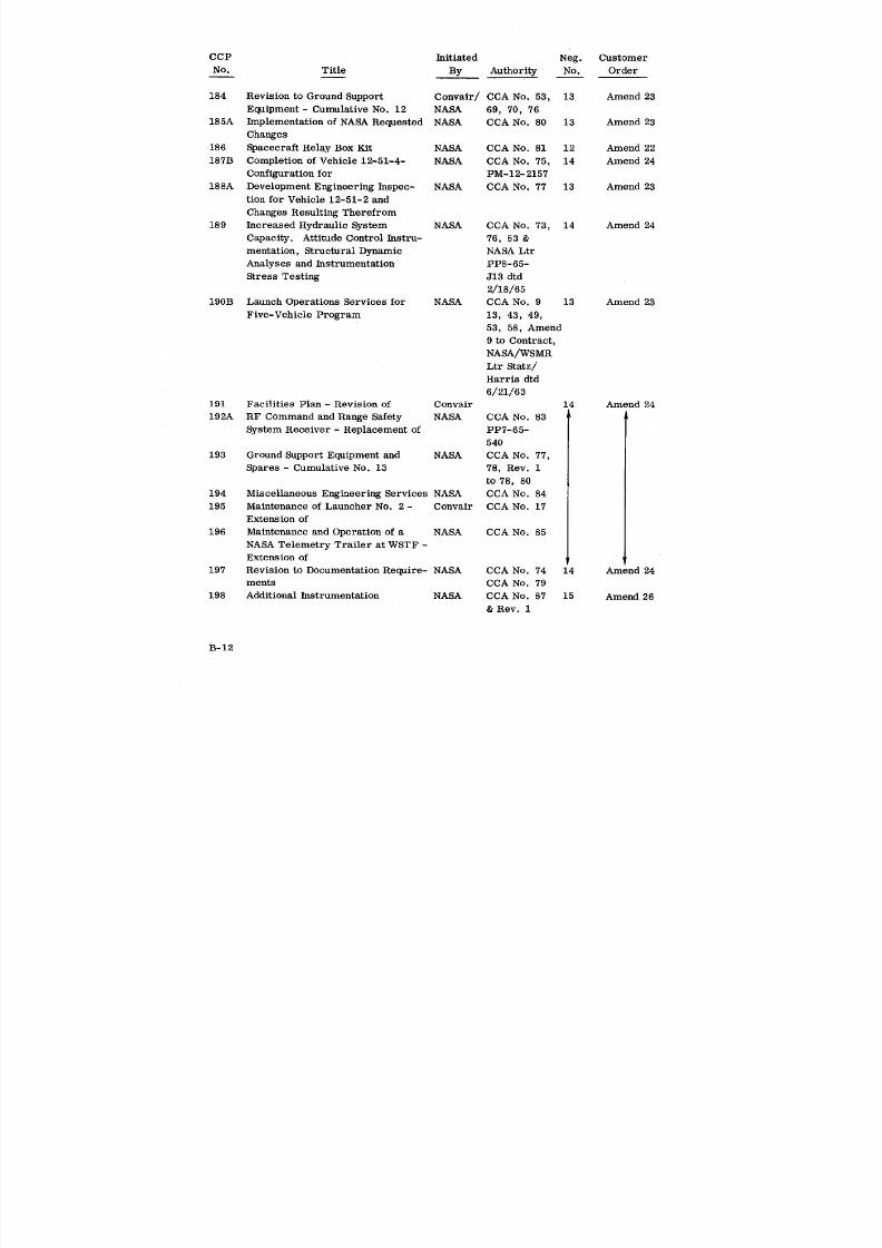
8/6/2019 Little Joe II Test Launch Vehicle NASA Project Apollo. Volume 1 Management
http://slidepdf.com/reader/full/little-joe-ii-test-launch-vehicle-nasa-project-apollo-volume-1-management 156/157
CCP Initiated Neg. Customer
No. Title By Authority No. Order
184 Revision to Ground Support Convair/ CCA No. 53, 13 Amend 23
Equipment- Cumulative No. 12 NASA 69, 70, 76
185A Implementation of NASA Requested NASA CCA No. 80 13 Amend 23
Changes
186 Spacecraft Relay Box Kit NASA CCA No. 81 12 Amend 22
187B Completion of Vehicle 12-51-4- NASA CCA No. 75, 14 Amend 24
Configuration for PM-12-2157
188A Development Engineering Inspec- NASA CCA No. 77 13 Amend 23
tion for Vehicle 12-51-2 and
Changes Resulting Therefrom
189 Increased Hydraulic System NASA CCA No. 73, 14 Amend 24
Capacity. Attitude Control Instru- 76, 83 &
mentation, Structural Dynamic NASA Ltr
Analyses and Instrumentation PP8-65-Stress Testing J13 dtd
2/18/65
190B Launch Operations Services for NASA CCA No. 9 13 Amend 23
Five-Vehicle Program 13, 43, 49,
53, 58, Amend
9 to Contract,
NASA/WSMR
Ltr Statz/
Harris dtd
6/21/63
191 Facilities Plan - Revision of Convair 14 Amend 24
192A RF Command and Range Safety NASA CCA No. 83
System Receiver - Replacement of PP7-65-
540
193 Ground Support Equipment and NASA CCA No. 77,
Spares- Cumulative No. 13 78, Rev. 1
to 78, 80
194 Miscellaneous Engineering Services NASA CCA No. 84
195 Maintenance of Launcher No. 2 - Convair CCA No. 17
Extension of
196 Maintenance and Operation of a NASA CCA No. 85NASA Telemetry Trailer at WSTF -
Extension of
197 Revision to Documentation Require- NASA CCA No. 74 14 Amend 24
merits CCA No. 79
198 Additional Instrumentation NASA CCA No. 87 15 Amend 26
& Rev. 1
B-12
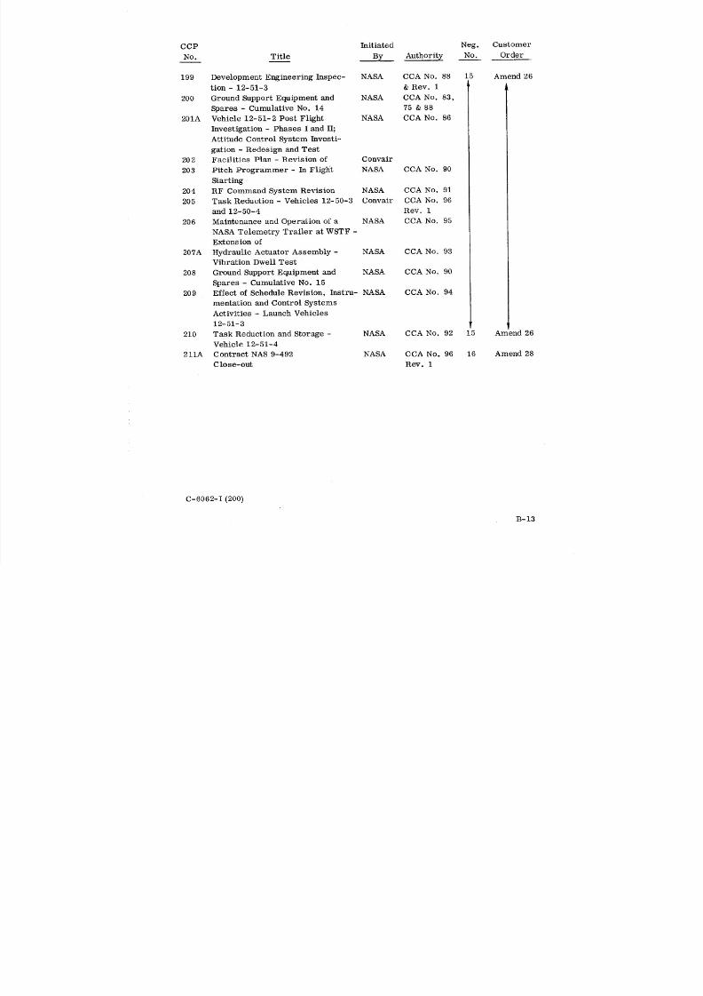
8/6/2019 Little Joe II Test Launch Vehicle NASA Project Apollo. Volume 1 Management
http://slidepdf.com/reader/full/little-joe-ii-test-launch-vehicle-nasa-project-apollo-volume-1-management 157/157
CCP Initiated Neg. Customer
No. Title By Authority No. Order
199 Development Engineering Inspec- NASA CCA No. 88 15 Amend 26
tion - 12-51-3 & Rev. 1
200 Ground Support Equipment and NASA CCA No. 83,
Spares - Cumulative No. 14 75 & 88
201A Vehicle 12-51-2 Post Flight NASA CCA No. 86
Investigation - Phases I and II;
Attitude Control System Investi-
gation - Redesign and Test
202 Facilities Plan - Revision of Convair
203 Pitch Programmer - In Flight NASA CCA No. 90
Starting
204 RF Command System Revision NASA CCA No. 91
205 Task Reduction - Vehicles 12-50-3 Convair CCA No. 96
and 12-50-4 Rev. 1206 Maintenance and Operation of a NASA CCA No. 95
NASA Telemetry Trailer at WSTF -
Extension of
207A Hydraulic Actuator Assembly - NASA CCA No. 93
Vibration Dwell Test
208 Ground Support Equipment and NASA CCA No. 90
Spares - Cumulative No. 15