linesanity: a journey from simple to complex linetypes
TRANSCRIPT

Linesanity: A Journey from Simple to Complex Linetypes
Sam Lucido – Haley and Aldrich, Inc.
AC1744
This class is filled with all the tips and trick’s you'll need to create new linetypes in AutoCAD®
. Yes, AutoCAD®
does supply us with several options for linetypes including dashes, dots and even shapes. What about creating
and designing custom lines based on your specific project needs? Well, in this class you’ll learn how to create a
compiled custom linetype library to be used for your company standard. Business needs creativity; in this class
you’ll gain that innovative knowledge to create new linetypes that catapult your drawings to the next level. Most
importantly, you’ll be able to bring value back to your employer and the knowledge to help you excel within your
field.
Learning Objectives:
At the end of this class, you will be able to:
Identify, change and create linetype definitions.
Create custom linetypes using fonts and shapes.
Create a complex linetype library using shapes.
Create a linetype tool palette with images. About the Speaker:
Sam Lucido is a sought out CAD designer and trainer at Haley and Aldrich, Inc. As a Senior CAD Designer he
presents workshops on CAD productivity to managers and users in both corporate/general settings and provides
support on a wide variety of mechanical and civil design projects. Sam has over 20 years of experience involving
production design and drafting, user support and standards coordination. He continues to be very self-motivated
and enjoys working in a team environment to accomplish project objectives and create high quality deliverables.
Sam is professionally certified in AutoCAD 2011 and AutoCAD 2012. [email protected] http://www.haleyaldrich.com http://www.cadprotips.com http://www.twitter.com/cadprotips

2
AutoCAD comes with a number of linetypes: continuous, dashed (various lengths), dotted, dash-dot, border, center, and so on. But you can make your own. A simple linetype is just a pattern of dashes, dots, and spaces. A complex linetype can include text and shapes. The linetype name and definition determine the particular dash-dot sequence, the relative lengths of dashes and blank spaces, and the characteristics of any included text or shapes. You can use any of the standard linetypes that AutoCAD provides, or you can create your own linetypes.
A LIN file is simply a text file that contains definitions of many simple and complex linetypes. You can add new linetypes to an existing LIN file, or you can create your own LIN file. To create or modify linetype definitions, edit the LIN file using a text editor or word processor or use the express tool MKLTYPE command (we will review this command later in this document). After you create a linetype, you must load the linetype before you can use it.
The LIN files included in AutoCAD are acad.lin and acadiso.lin. AutoCAD comes with a number of simple and some complex linetypes stored in acad.lin and found in the \support folder under (C:\Users\xxxxxx\AppData\Roaming\Autodesk\AutoCAD 2013 - English\R18.2\enu\Support). See the image
belowfor an example of the lines that are supplied with AutoCAD.

3
I have highlighted 3 linetypes as shown above that we will be exploring. As you can see a linetype is a series of
positive and negative numbers that tell AutoCAD how long to lower or raise a pen. Positive numbers lower the
pen (draw a line), negative numbers will raise it (create a space).
Let’s start by creating a simple linetype with the dashed line since that one is the easiest to explain. For the
code this would be just lines and spaces.
*DASHED,Dashed __ __ __ __ __ __ __ __ __ __ __ __ __ _
This first line will start with an (*) asterisk which will tell AutoCAD that it’s a descriptor and not to use the code. Immediately following the * is the name of the linetype (DASHED) followed by a comma. After the comma you can enter the name of your linetype and follow it up with text characters or the ASCII code to define the line. You should keep the description to 45 characters, anything over that would be hard to read in the linetype manager. Let’s review those numbers. The second line must begin with the letter A (alignment), followed by a list of pattern descriptors that define pen-up lengths (spaces), pen-down lengths (dashes), and dots. You can include comments in an LIN file by beginning the line with a semicolon (;).
Let’s take a look at the letters and number of a few linetypes. Notice the syntax for DASHED is A,.5,-.25
A = alignment (required)
The letter A is the alignment field which specifies the action for pattern alignment at the ends of individual lines, circles, and arcs.
.5 = tells AutoCAD to lower the pen and move .5 units
-.25 = tells AutoCAD to raise the pen and move .25 units
Notice below that after the -.25 space the linetype begins to repeat itself starting with the .5 distance again and continuing on with the pattern.
The numbers indicate a repeating pattern starting with a dash 0.5 drawing units long, a space 0.25 drawing units
long. This pattern continues for the length of the line. One more element that is included with AutoCAD linetypes
is the dot. Let’s review the linetype file again looking at the divide line as shown below. Notice the syntax for
DIVIDE is A, .5,-.25, 0,-.25, 0,-.25
A = alignment (required)
.5 = tells AutoCAD to lower the pen and move .5 units
-.25 = tells AutoCAD to raise the pen and move .25 units
0 = tells AutoCAD to place a dot
Notice the 0 segments below and see the illustration to show where the dots will be placed within our line.
4
Now that we have reviewed the basics, let’s create a simple linetype.
We will create a water line shown to the right which is typically
represented by 3 dots and a dash as shown.
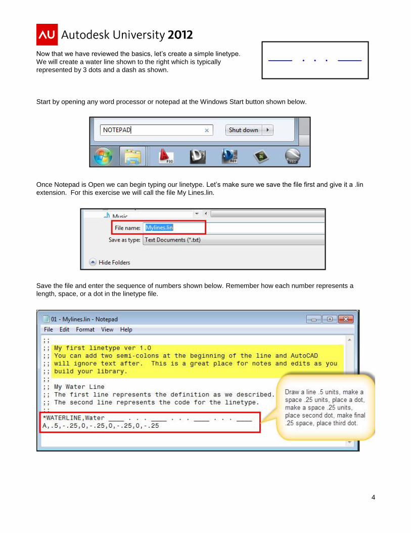
Start by opening any word processor or notepad at the Windows Start button shown below.
Once Notepad is Open we can begin typing our linetype. Let’s make sure we save the file first and give it a .lin
extension. For this exercise we will call the file My Lines.lin.
Save the file and enter the sequence of numbers shown below. Remember how each number represents a
length, space, or a dot in the linetype file.

5
Now you have created the linetype and must load this into AutoCAD. Just type Linetype and hit the load button as
shown below. You can now create several linetypes of your own just follow the standard syntax that is required for
lines, spaces, and dots.
After you select the load button browse out to the folder where you have stored the linetype file and select it and
the waterline will be shown. Select the waterline and that linetype will now be loaded into your current drawing.
HINT! You can save this to a template to load in AutoCAD each and every time.
Let’s continue on and create a complex linetype using fonts to represent specific design criteria. This is where the fun begins! A complex linetype includes either shapes or text within the definition file. Complex linetype definitions are similar to the simple linetype, except there is a definition for the shape or text which will be included within the syntax.

6
We are going to start out by adding a unique text style to our drawing. You can use any style of your preference
although I find it best to create a dedicated linetype for text styles. You will have less room for the possibility of
someone adding a height to your style. For this example we will name the style linetypes and set that style for the
Arial font with a ‘0’ height. It is very important to define it with a Height of ‘0’. Using a true type font you can take
on the characteristics of that font style which is benefit of True Type fonts. I have highlighted the areas below to
illustrate the items that you will need to change to create the linetype. Notice that there is another linetype in
Styles area name Winglines. No need to create that just yet, we will be using that one later in this document.
Let’s create a linetype with the letter A for AIR. Similar to our dash dot linetype but for this one AutoCAD will
display the Letter A in the middle of the line. Open up the Myline.lin file and add the following sequence for
another line.
*AIR,Air Flow ----- A ----- A ----- A -----
A,.5,-.12,["A",LINETYPES,S=.12,R=0,X=-.06,Y=-.06,U=0],-.12

7
Take a look at Figure 1 (below) and match up the numbers in your line with what is dimensioned. This will give
you a better idea of what those numbers represent graphically.
The parameters remain the same except for a new string which will be enclosed in brackets. Everything within the
brackets controls the text size, position and rotation. A description of what each letter or bracket represents is
shown in Figure 2 (below).
[ ] = enclose the text string and parameters.
A = tells AutoCAD what should be displayed in the text
S = scale of the font.
R = set this to 0. Sets the rotation of the text to 0, relative to the line.
X = is the x-offset (shifts the text along the x axis
Y = is the y-offset (shifts the text along the y axis
U = upright variable to control the position of the text.
Figure 1
Figure 2

8
The colors shown below represent the parameters that are set within the line. Now if we want to create another
line with a different letter simply copy and paste this line and just change the font! You could make lines for every
letter in the alphabet.
What if the line you want has more letters? Simply take that .12 at the end and add .12 and this will accommodate
for more letters. Let’s do that for two more additional lines as shown. Try it out with 5 or 6 letters or maybe even
some numbers.
Type load at the command prompt and select the Myline.lin file and see the results. Notice you have 4 lines as
shown below ready to use in AutoCAD. You will need to select that line and hit OK or right click and select all the
lines to load into AutoCAD.

9
Take a look at what we have. We have three linetypes with syntax correct for up to three letters. Let’s just copy those lines, change the letters, and make 3 more.
Copy and paste the text and change the letters below. Simple, right? Now load up AutoCAD and your Myline.lin file and you will see the new 3 lines (as shown below) ready to be used in AutoCAD

10
We have just covered the basics of creating a simple linetype and a complex linetype with text. You can use these techniques to create multiple lines with dashes, dots, and text. We have just created the base for our standard linetype file and have 6 new lines! Not all fonts represent the same width so try out different versions but remember to complete set first then copy and paste as you build the file.
HINT! Remember, the font style must have a height set to ‘0’ for these linetypes to display correctly. If not, the S
variable will transform the size of the font by the number that you have placed in there. Just add the style to your standard template.
Express Tools: Make Linetype Command
Yes, there is a make linetype command! I know I made you go through all that text syntax and code when you can simply use the Mkltype command. This is true but the first version will gain you consistency. Let’s explore how to use the Make Linetype command and how it works.
Create your geometry in AutoCAD how you would like your linetype to display. Draw the linetype at a scale of 1:1. Draw a line 2 units in length and place a piece of text (A) in the center of the line. Use DTEXT (not mtext); LINETYPE text style with a .12 height and the MC (Middle Center) justification for the text. Simply type the trim command and trim the line around the text. To achieve best results offset an equal distance from the center of the text grip, then trim the line. Your image should look like this the line shown below.
Move to the Express Tools Tab on the Ribbon and Select Make Linetype (as shown below) or type MKLTYPE at the command prompt.
By selecting Make linetype you will issue the mkltype command. We will now go through the series of commands (found on the next page) that can be found in the AutoCAD Express Tools Help Menu.

11
1. Command: MKLTYPE
2. Select a ".LIN" file: <C:\AU2012\The Linesanity Project\mylines.lin>: We can enter any name
for our line.
NOTE: If you select an existing .lin file (as we did), the file dialog box warns you that the file will be replaced; however, the file is actually appended to. If you choose to create a linetype with the same name as one that already exists in the selected .lin file, an overwrite warning appears. If you choose yes, the existing linetype is overwritten, but the rest of the file remains intact.
3. Enter linetype name: Specify a linetype name A
4. Linetype description: Specify a linetype description NEW AU2012 LINE
5. Starting point for line definition: Specify a starting point (Point 5 below)
6. Ending point for line definition: Specify an ending point (Point 6 below)
7. Select objects: Select all three objects from the left to right
Seems a bit easier than typing all that code, right? Now let’s take a look at the results. AutoCAD is getting the
exact point to where that line ends. On our example these are consistent throughout. I like consistency and feel
you should get a good set of code that you can remember and work with. Sure, you can create all of your lines
this way but you may end up with a very confusing file when it comes to editing.
Notice that the numbers shown below have many decimal places and are random. With our first one that we
added in, we could keep the numbers a consistent format and copy and paste. You can do the same with this
version but I like to keep things clean and rounded off the whole numbers or two decimal places. If you copy and
paste these numbers will you remember what they mean a year from now? We will delete that linetype in our file
and continue on with something more fun.

12
We are getting smarter! Let’s continue with fonts and do something fun with the standard windows WINGDINGS font. Remember we created that linetype style (on page 6) in the beginning of this lesson? We are going to now create the Winglines style using the windings font.
First released in 1990 by Microsoft, Wingdings is a font that uses symbols instead of traditional letters and numbers. The initial Wingdings font had a wide range of symbols, from religious symbols and telephone symbols to shapes. There are three versions of Wingdings, and Wingdings 2 and Wingdings 3 were introduced around the same time as the original Wingdings. Let’s use the original Windings font and create a style named wing and set the height to 0.
Take a look at a standard character map for the wingdings font. We can take any of those images (since all computers with Windows come with the windings font. We just have to find out what letter corresponds to the image on the map.
We are going to make 3 new linetypes to add to our drawing. We will make SMILE, TNT, and THUMBSUP. The following image will show what the 3 new lines will look like.
Create a new text style in AutoCAD named WINGLINES and give it a 0 height. Do not make the style annotative. Next draw the geometry as we did before and set the style to WINGLINES. Using DTEXT type in the letters C, M, and D one on top of the other. You will get the thumbs up symbol, smile symbol, and the TNT symbol.

13
Next, draw three lines as before and place those lines within the center and trim as shown in the image below. Notice that the distances from the center of the font to the beginning of the next line are not as close to what they would be for a normal font. This is why we will be using the MKLTYPE command for this section.
We will now go through the series of commands again that can be found in the AutoCAD Express Tools Help Menu.
1. Command: MKLTYPE
Select a ".LIN" file: <C:\AU2012\The Linesanity Project\mylines.lin>:
We can enter any name for our line (you can also rename that linetype file later as well. It must have a .lin extension in order for AutoCAD to read the file.
2. Enter linetype name: Specify a linetype name SMILE
3. Linetype description: Specify a linetype description SMILE WITH ME
4. Starting point for line definition: Specify a starting point (Point 5 in example below)
5. Ending point for line definition: Specify an ending point (Point 6 in example below)
6. Select objects: Select two objects from the left to right as shown. Do not select the third line in sequence, which is for reference only.
14
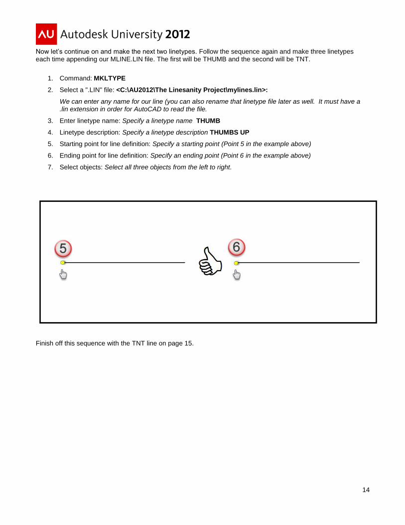
Now let’s continue on and make the next two linetypes. Follow the sequence again and make three linetypes each time appending our MLINE.LIN file. The first will be THUMB and the second will be TNT.
1. Command: MKLTYPE
2. Select a ".LIN" file: <C:\AU2012\The Linesanity Project\mylines.lin>:
We can enter any name for our line (you can also rename that linetype file later as well. It must have a .lin extension in order for AutoCAD to read the file.
3. Enter linetype name: Specify a linetype name THUMB
4. Linetype description: Specify a linetype description THUMBS UP
5. Starting point for line definition: Specify a starting point (Point 5 in the example above)
6. Ending point for line definition: Specify an ending point (Point 6 in the example above)
7. Select objects: Select all three objects from the left to right.
Finish off this sequence with the TNT line on page 15.

15
1. Command: MKLTYPE
2. Select a ".LIN" file: <C:\AU2012\The Linesanity Project\mylines.lin>:
We can enter any name for our line (you can also rename that linetype file later as well. It must have a .lin extension in order for AutoCAD to read the file.
3. Enter linetype name: Specify a linetype name TNT
4. Linetype description: Specify a linetype description TNT DYNOMITE
5. Starting point for line definition: Specify a starting point (Point 5 in the example above)
6. Ending point for line definition: Specify an ending point (Point in the example above)
7. Select objects: Select all three objects from the left to right
NICE JOB! Done with all the basics now let’s get to those shapes!

16
We need to look at an overview of shapes and what they are. Shapes are objects that you use like blocks. First you use the LOAD command to load the compiled shape file containing the shape definition. Then you use the SHAPE command to insert shapes from the file into your drawing. You can specify the scale and rotation to use for each shape as you add it. Shapes are very small in size and must be contained within the drawing file to appear. Linetype definitions in AutoCAD support the use of shapes. Blocks are more versatile and easier to use and apply than shapes. However, shapes are more efficient for AutoCAD to store and draw. User-defined shapes are helpful when you must insert a simple part many times and when speed is important. Just a couple of things to keep in mind while drawing and creating objects.
When you use a shape in a linetype it must be compiled. After the shape has been compiled it then can be loaded into the AutoCAD to be used in the linetype definition.
How do I do that? Compiling a shape definition file (SHP) generates a compiled shape file (SHX). Being able to create your own shape definitions is a valuable skill. Keep in mind, however, that this is a very complex subject to learn and requires patience. We are going to focus on how to use the MKSHAPE command in the express tools to make and define our shapes. Entering ASCII format can become very complicated and some files will be hard to compile. First we have to create our shape in AutoCAD. Remember our font was a .12 height? Let’s create a circle in AutoCAD. Simply run the circle command and create a circle with a diameter of .1. I want to use .1 since we will be using the scale factor on the shapes to determine the size within the linetypes. We have to keep things simple when it comes to shapes and lines.
After the circle has been created use the hatch command to fill in the circle (solid hatches are not accepted in a shape file. Use the settings shown below then explode the hatch to create separate entities within the shape. We want this to look like a solid fill but we do not want to have too many lines in our shape definition.
We will now make a couple more shapes and see how we can use those in our linetypes. We will create a solid arrow and a solid box. Let’s draw the shapes in AutoCAD using that .1 length as a reference for our shapes. HINT: for the solid squares and triangles we will use the ANSI31 hatch and explode the hatch pattern (as shown above). Notice how the objects do not appear solid but you have to remember that these objects will not be as large as they are shown and the objects will appear solid within the line(s). Create the 3 shapes as shown below.

17
Now that we have our three objects created we need to make those objects into shapes. Type MKSHAPE at the command prompt or access it from the Ribbon under express tools as shown below.
The compiled file has the same name as the shape definition file but with a file type of SHX. If the shape definition file defines a font, you use the STYLE command to define a text style. Then, you use one of the text placement commands (TEXT or MTEXT) to place the characters in the drawing. If the shape definition file defines shapes, you use the LOAD command to load the shape file into the drawing. Then, you use the SHAPE command to place the individual shapes in the drawing (similar in concept to the INSERT command).
Type MKSHAPE and AutoCAD will bring up the file name dialog box as shown. AutoCAD shape files are stored outside the drawing and are referenced from a file with a .shp or .shx extension. You can name this Myshapes.shp and just append each time just like we did in the linetype example. For this example we will just create 3 for each shape. Name the first one solidcircle.
Name your first shape solidcircle. Make sure you use an insert point as if you were to use a block (We will use the center of the circle). This becomes important when you are defining your linetype definitions. Select the objects and your shp and shx files will be created. Review the highlighted sections below to see what AutoCAD has done. We created a shape named solidcircle and also compiled the shape.

18
Create the next two shapes SOLIDBOX and SOLIDARROW. It’s good to call the shapes something that we can remember. When you have hundreds you need to stay organized. Check your folder to see if the shapes have been created and compiled. We will move those later to a separate folder to keep things organized. We now have our shape files (shp) and our compiled shape files (shx). These we will need to be in the AutoCAD support file project path for AutoCAD to load the shapes (or in the current working folder). We will now create 3 linetypes with the shapes as shown below. We are going to create the look of our lines using a length of 1.0. Draw 3 line segments in your drawing and space them apart so you can add the shapes. It is a good idea to have a template file with all of these lines in there with the dimensions shown (a good reference).We are going to follow the same pattern and sequence we used when we created the linetypes with the fonts. Place your shape at the center of the line and break the object equal distance on each side.
Pick the start of the line (blue 1), end of the line (blue 2), then the objects from left to right (as shown below). Use the object snap endpoint and select under the 1 and 2 blue circles. You will now be asked to select the objects. Select two objects, the line, and then the arrow.
TRI-LINE
19
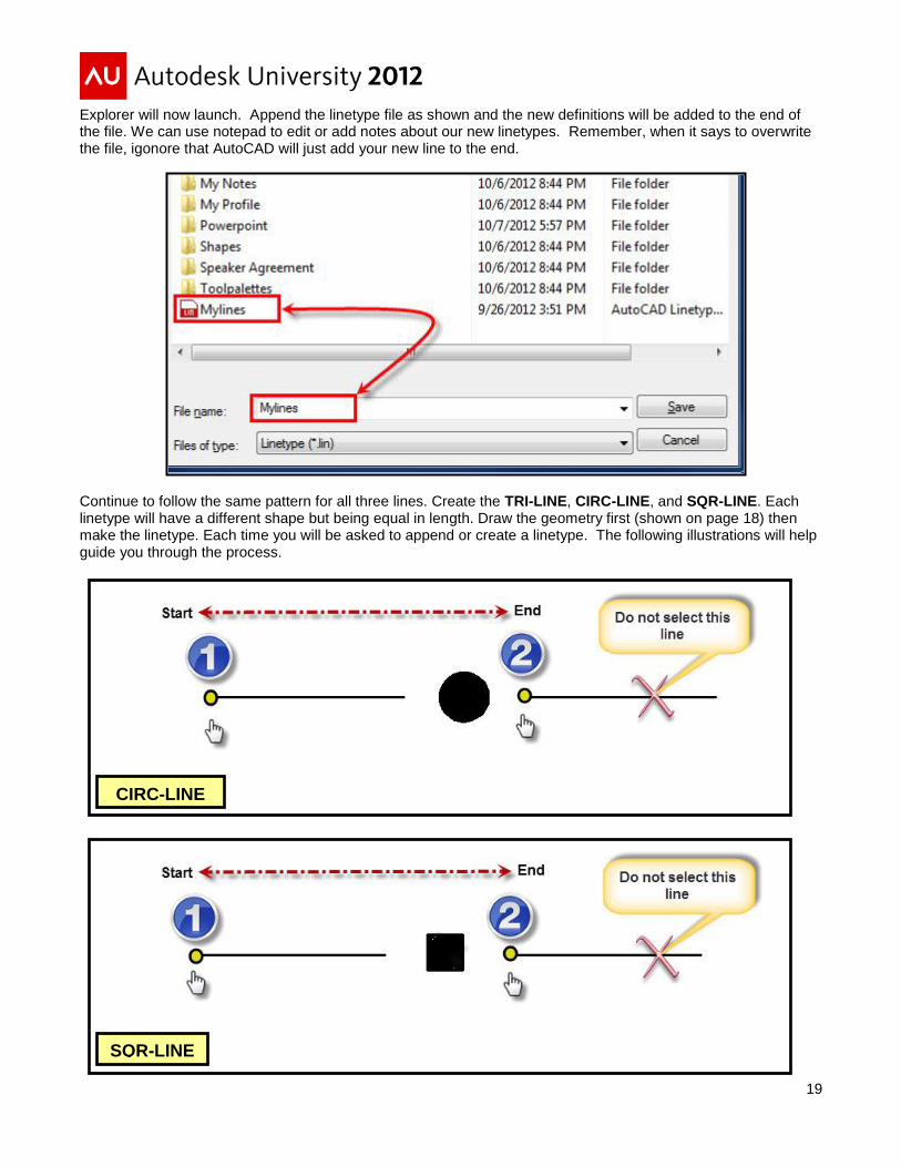
Explorer will now launch. Append the linetype file as shown and the new definitions will be added to the end of the file. We can use notepad to edit or add notes about our new linetypes. Remember, when it says to overwrite the file, igonore that AutoCAD will just add your new line to the end.
Continue to follow the same pattern for all three lines. Create the TRI-LINE, CIRC-LINE, and SQR-LINE. Each linetype will have a different shape but being equal in length. Draw the geometry first (shown on page 18) then make the linetype. Each time you will be asked to append or create a linetype. The following illustrations will help guide you through the process.
SQR-LINE
CIRC-LINE

20
Let’s take a look at the text file (Mylines.lin) and see what we have created. I have highlighted the name of the shape. Notice immediately after it shows the path of the shape. This is the path that you will store your linetypes and add to the configuration settings in AutoCAD.
We have now created linetypes using dashes, dots, fonts, shapes, and lines. We now want to create a shape library so we do not have hundreds of files out on the network. Let’s make 3 more lines using those existing shapes then compile the shapes into a library. Let’s take a quick look at our 3 shapes again.
Note: Shapes must fall within the linetype definition. That being said, if you just have shapes within your linetype you will end up with a dot at the front or the end of your line. We are now going to make linetypes that will consist of a combination of shapes and lines. It is important if you just have shapes AutoCAD will place a dot (pen down) at the point where it is supposed to draw a line. Keep you shapes together and play with the one of the system variables (ltscale or celtscale) to determine what best works for you.

21
Start by drawing a line again, make it 1 unit long and begin to place shapes as shown below. Type the shape command and insert the shape at the midpoint or on the line where you would like it to be displayed. Add more shapes; trim the line out, and get the lines to look exactly like you want. Make the three lines as shown, they do not have to be exact but try and keep the shapes at a uniform distance. This will ensure that your lines will be displayed correctly when used on a drawing. The next page will begin a detailed description of how to make these lines. I will explain those red and green lines below when we get to that linetype.
Now that the geometry has been created we will create the first line; the DITCH line with a flow direction arrow.
Type the MKLTYPE command or go to the ribbon under express tools and select the command. It will
immediately launch a window asking for the Linetype (.LIN) file. Simply select the same one we have been using
the MLINE.LIN file. Remember, AutoCAD will append this linetype file and place any new lines at the end.

22
The following images (Figure L1, L2, and L3) will represent the lines and the order you will select the geometry to
create those lines. Zoom in you drawing to the ditch line that you have drawn. Select the geometry in the
sequence as shown in Figure L1. The blue circles will represent the length of our line from start to finish. The
square numbers represent the objects we will select when creating the line
Do the same for the wood barrier. Type the MKLTYPE command and create the line. Keep appending the
MYLINE.LIN file. We will review that when complete.
Finally, create the waste line as shown in Figure L3. Each time appending your original MYLINE.LIN file. For the
waste line I did not enter the numbers since there are no lines and just shapes. When creating this line only use
2-3 shapes so the file will not be too large. You do not need to stretch the shapes out to create a line 1 unit in
length.
Figure L1
Figure L2

23
Notice the red and green lines. Those are only there for reference and to keep our distance consistent between
the shapes. We will only use those lines when creating our start and end length of our line (1 and 2).
Using a linetype with just shapes will cause AutoCAD to create dots or spaces. If you have a closed polylines you
will not see this affect. Let’s now take a look at the text file to see how those shapes were placed in the linetype
file. When not drawing a closed polylines you may see this on current drawings. From the customization guide:
When the linetype is drawn, AutoCAD uses the first pattern descriptor for the starting and ending dashes. Between the starting
and ending dashes, the pattern dash specifications are drawn sequentially, beginning with the second dash specification and
restarting the pattern with the first dash specification when required.A-type alignment requires that the first dash length be 0 or
greater (a pen-down segment).It's that 0-length pen-down segment at the beginning of your pattern description that you're
seeing at the ends
Using windows explorers go back out to your .lin file and open it up. You will see something similar to what I have
shown below. Notice how AutoCAD keeps the path for the shapes (.shx) files. This is where we will combine all of
those into one compiled shape file and place in the support search path for easy access.
Figure L3
24
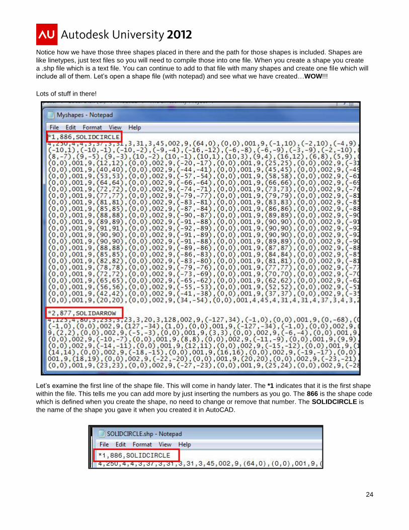
Notice how we have those three shapes placed in there and the path for those shapes is included. Shapes are
like linetypes, just text files so you will need to compile those into one file. When you create a shape you create
a .shp file which is a text file. You can continue to add to that file with many shapes and create one file which will
include all of them. Let’s open a shape file (with notepad) and see what we have created…WOW!!!
Lots of stuff in there!
Let’s examine the first line of the shape file. This will come in handy later. The *1 indicates that it is the first shape
within the file. This tells me you can add more by just inserting the numbers as you go. The 866 is the shape code
which is defined when you create the shape, no need to change or remove that number. The SOLIDCIRCLE is
the name of the shape you gave it when you created it in AutoCAD.
25
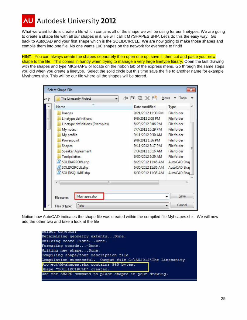
What we want to do is create a file which contains all of the shape we will be using for our linetypes. We are going
to create a shape file with all our shapes in it, we will call it MYSHAPES.SHP. Let’s do this the easy way. Go
back to AutoCAD and your first shape which is the SOLIDCIRCLE. We are now going to make those shapes and
compile them into one file. No one wants 100 shapes on the network for everyone to find!!
HINT: You can always create the shapes separately then open one up, save it, then cut and paste your new
shape to the file. This comes in handy when trying to manage a very large linetype library. Open the last drawing
with the shapes and type MKSHAPE or locate on the ribbon tab of the express menu. Go through the same steps
you did when you create a linetype. Select the solid circle but this time save the file to another name for example
Myshapes.shp. This will be our file where all the shapes will be stored.
Notice how AutoCAD indicates the shape file was created within the compiled file Myhsapes.shx. We will now
add the other two and take a look at the file

26
After adding the other two shapes your text file should look something like this. I removed a lot of the code from
the shapes since I wanted to show you how the *1 represents the number of the shape. You can add spaces
before and after the shape to help you describe what the shape is and what it is used for. If you create another
shape simply add to the end of the file with the next number.
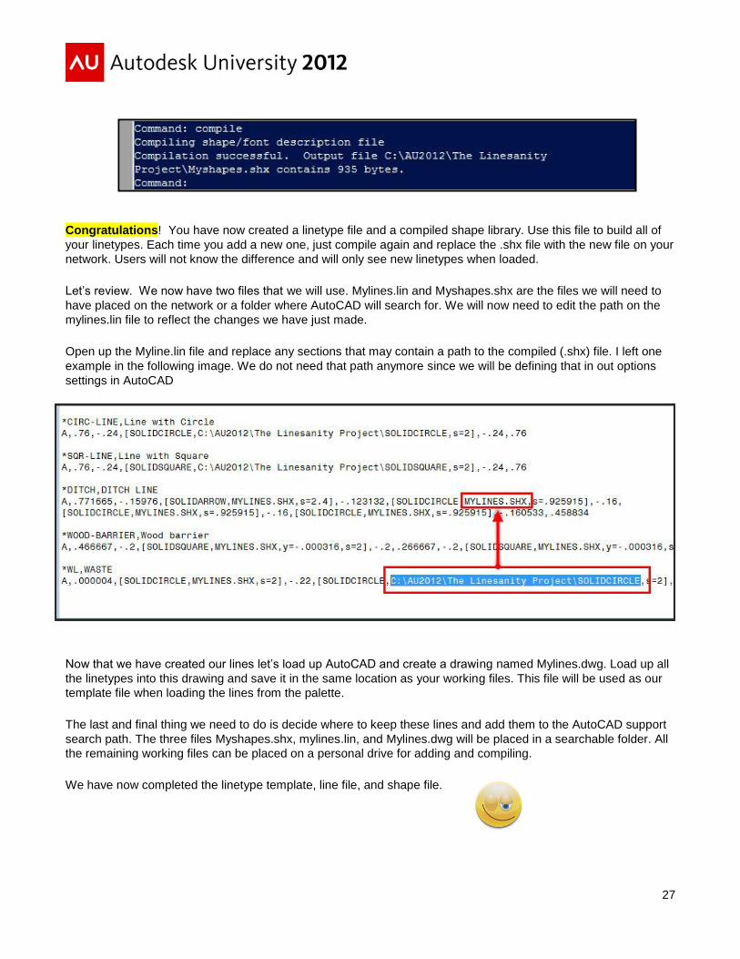
We are almost there. Now let’s create our compiled shape library (the .shx file). The reason we need to do this is
when we put our linetype file on the network AutoCAD will only need 2 files to search for. The Mylines.lin file and
the associated shape file which will be Myshapes.shx. Type compile at the command prompt and the following
dialog box will appear. Select the Myshapes.shp file and AutoCAD will compile (create) the .shx file for your use.
27
Congratulations! You have now created a linetype file and a compiled shape library. Use this file to build all of
your linetypes. Each time you add a new one, just compile again and replace the .shx file with the new file on your
network. Users will not know the difference and will only see new linetypes when loaded.
Let’s review. We now have two files that we will use. Mylines.lin and Myshapes.shx are the files we will need to
have placed on the network or a folder where AutoCAD will search for. We will now need to edit the path on the
mylines.lin file to reflect the changes we have just made.
Open up the Myline.lin file and replace any sections that may contain a path to the compiled (.shx) file. I left one
example in the following image. We do not need that path anymore since we will be defining that in out options
settings in AutoCAD
Now that we have created our lines let’s load up AutoCAD and create a drawing named Mylines.dwg. Load up all
the linetypes into this drawing and save it in the same location as your working files. This file will be used as our
template file when loading the lines from the palette.
The last and final thing we need to do is decide where to keep these lines and add them to the AutoCAD support
search path. The three files Myshapes.shx, mylines.lin, and Mylines.dwg will be placed in a searchable folder. All
the remaining working files can be placed on a personal drive for adding and compiling.
We have now completed the linetype template, line file, and shape file.

28
Time to put our library of lines on Tool palettes!
In this section we are not going to go over tool palettes in great detail but merely show you how to add those lines
to a palette. AutoCAD's Tool palette feature is one of the easiest ways to create and manage reusable content in
AutoCAD. You can easily access the AutoCAD Tool palette using Ctrl-3 (my preference), using the Tools pull-
down menu, or using the standard toolbar. You can only have one overall palette on the screen at a time, with as
many tabs as you see fit. We need to get those lines on the palette, and with a selection have those lines load
and be drawn on the correct layer. We are going to create a new tool palette similar to what is shown on the right.
First, I would like to refer to Matt Murphy’s classes at AU2011 and AU2012:
AC4814: Managing your standards and reusable content with AutoCAD®
Tool Palettes – Revealed!
(This class was presented at Autodesk University 2011)
AC3441: The Productivity Power of AutoCAD®
Tool Palettes – Revealed!
(This class was presented at Autodesk University 2012).
I used Matt’s technique of creating an macro to locate the tool palette path which gives the illusion of groups. This
works great when switching between different groups of blocks, command tools and engineering disciplines. We
will go through this briefly to assist you in getting things setup. Just like managing your support path statements in
AutoCAD, you can set a Tool Palette path location and not use the group feature.
29
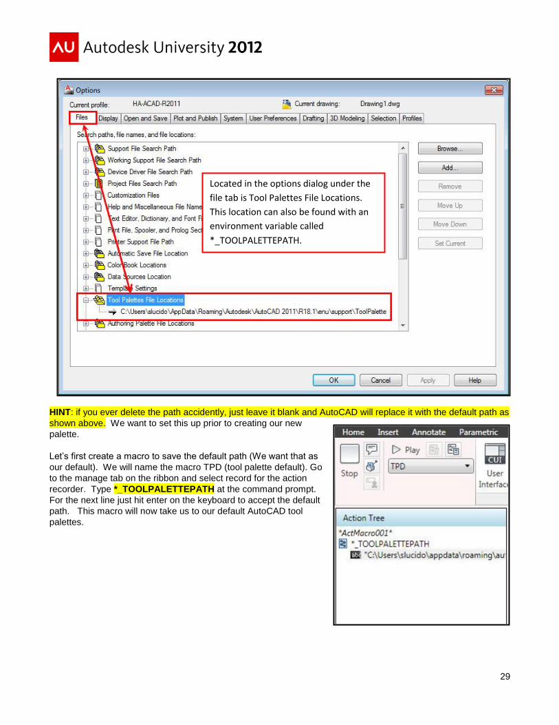
HINT: if you ever delete the path accidently, just leave it blank and AutoCAD will replace it with the default path as
shown above. We want to set this up prior to creating our new
palette.
Let’s first create a macro to save the default path (We want that as
our default). We will name the macro TPD (tool palette default). Go
to the manage tab on the ribbon and select record for the action
recorder. Type *_TOOLPALETTEPATH at the command prompt.
For the next line just hit enter on the keyboard to accept the default
path. This macro will now take us to our default AutoCAD tool
palettes.
Located in the options dialog under the
file tab is Tool Palettes File Locations.
This location can also be found with an
environment variable called
*_TOOLPALETTEPATH.
30
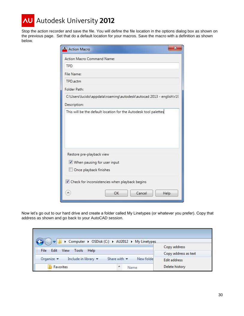
Stop the action recorder and save the file. You will define the file location in the options dialog box as shown on
the previous page. Set that do a default location for your macros. Save the macro with a definition as shown
below.
Now let’s go out to our hard drive and create a folder called My Linetypes (or whatever you prefer). Copy that
address as shown and go back to your AutoCAD session.
31
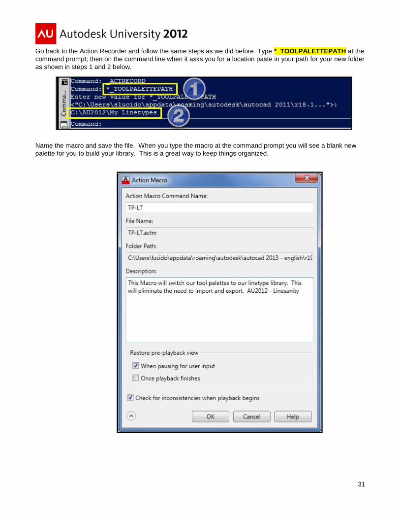
Go back to the Action Recorder and follow the same steps as we did before. Type *_TOOLPALETTEPATH at the
command prompt; then on the command line when it asks you for a location paste in your path for your new folder
as shown in steps 1 and 2 below.
Name the macro and save the file. When you type the macro at the command prompt you will see a blank new
palette for you to build your library. This is a great way to keep things organized.

32
Take a look; you now have a blank new palette to work with. Simply Right click on the palette tab and rename the
palette to My Linetypes. Remember, you can always type TPD at the command prompt and you will get right
back to the AutoCAD default palettes.
If you copy your linetype Tool Palette folder to a secure location on your network, you can use a macro just like
above to switch to that location. You can also copy the AutoCAD default tool palette folder to the network and
complete the same task. This is a great way to share Tool Palette content while allowing users to add and
manage their own content by having multiple tool palette paths.
Now that we have a blank new palette we will rename that palette to My Linetypes and start to build our library.
Right-click on the palette name and type in My Linetypes. Now we need to start building our palettes based off our
template. There are many ways to configure palettes using commands. We are going to insert our template then
set the linetype and run the pline command. You can choose to run the line command, circle, or whatever you
prefer.
We need to get a command in there so we can build. We can use the cui but let’s make it easy and just draw a
line or a circle in our drawing. Then right click on that object and drag that object over to the tool palette. You now
have a command in there that we can begin to edit.

33
Right click on the circle command and edit the fields to your preference. The example below shows the fields that
are important for creating our linetype library. HINT: For the layer section simply create the layer and it’s
properties within you current drawing and you will be able to add to the layer section. AutoCAD will hold
that value to use in a new drawing session.
We now need to edit the remaining files especially the command string to get our linetypes to work and load in
AutoCAD. Our goal is to eliminate the extra steps and make life easy by having these linetypes represented by
an image, description and a command string which will automate the process in AutoCAD.
34
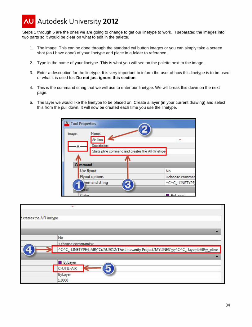
Steps 1 through 5 are the ones we are going to change to get our linetype to work. I separated the images into
two parts so it would be clear on what to edit in the palette.
1. The image. This can be done through the standard cui button images or you can simply take a screen
shot (as I have done) of your linetype and place in a folder to reference.
2. Type in the name of your linetype. This is what you will see on the palette next to the image.
3. Enter a description for the linetype. It is very important to inform the user of how this linetype is to be used
or what it is used for. Do not just ignore this section.
4. This is the command string that we will use to enter our linetype. We will break this down on the next
page.
5. The layer we would like the linetype to be placed on. Create a layer (in your current drawing) and select
this from the pull down. It will now be created each time you use the linetype.

35
Let’s review the command string to see what AutoCAD is doing. This section is where you can add custom commands, even diesel, and macros to get AutoCAD to do what you need to do. Take a look at the line and the syntax. You notice that it follows a command sequence in AutoCAD.
^C^C_-LINETYPE;L;AIR;"C:/AU2012/The Linesanity Project/MYLINES.LIN";Y;;^C^C_-layer;lt; AIR;;;_pline
The following page (Table 1) has an excel table which describes what each command will do. In AutoCAD type the commands as shown and you will see what AutoCAD does to get those lines loaded.
You did it! Now it’s time to build the tool palette for your company standard. Simply copy and paste the
command string changing the name of the linetype each time. Create your own image and place on the palette.
Remember those images will be saved under the tool palette path system variable.
Table 1

36
I would say the last linetype (on Figure 1) says it all. Thumbs up! Good job and continue to share and build those
linetypes! The following pages contain system variables which control the appearance and settings of linetypes
within AutoCAD. I put those in there as a reference for you when you create your library.
Figure 1
Good Job!

37
Linetype notes, system variables and additional information:
AutoCAD currently does not support linetype definitions that begin with an empty segment. If you try to create a
linetype that begins with an empty segment, the program adds a dot to the beginning of the definition. Be aware
that these dots will show up on your drawing and can confuse the operator. To avoid confusion and keep
consistency throughout the linetypes and visibility issues you could set your linetypes “Bylayer,” and ltscale to 1.
This next section will cover the variables which can affect the appearance of linetypes.
LTSCALE Linetype Scale - Controls overall linetype scaling of objects displayed. This is the Global Linetype
Scale Factor (system variable) value which changes the linetype scale globally for both new and existing objects.
ltscale factors <1 make line segments smaller. ltscale factors >1 make line segments larger. The default setting
is 1.

38
CELTSCALE Current Element Linetype Scale – Sets the current object linetype scaling factor. You can force an
individual elements LTSCALE with this setting (system variable) value controls the linetype scale for new objects.
The celtscale value is a scaling factor applied to the current ltscale value. The default setting is 1.
MSLTSCALE Model Space Linetype Scale – Scales linetypes displayed on the model tab by the annotation scale. For model space or a layout viewport, you can display all the annotative objects or only those that support the current annotation scale. This reduces the need to use multiple layers to manage the visibility of your annotations.

39
PSLTSCALE Paper Space Linetype Scale – Controls linetype scaling of objects displayed in paperspace
viewports.
0 = No special linetype scaling. Linetype dash lengths are based on the drawing units of the space (model or
paper) in which the objects were created and scaled by the global LTSCALE factor.
1 = Viewport scaling governs linetype scaling. If TILEMODE is set to 0, dash lengths are based on paper space
drawing units, even for objects in model space. In this mode, viewports can have varying magnifications, yet
display linetypes identically. For a specific linetype, the dash lengths of a line in a viewport are the same as the
dash lengths of a line in paper space. You can still control the dash lengths with ltscale.
When you change PSLTSCALE or use a command such as ZOOM with psltscale set to 1, objects in viewports
are not automatically regenerated with the new linetype scale. Use the REGEN or REGENALL command to
update the linetype scales in each viewport.

40
Enjoy the rest of your time at Autodesk University 2012!