linear vibration feeder - worcester polytechnic institute allows engineers to program machines to...
TRANSCRIPT
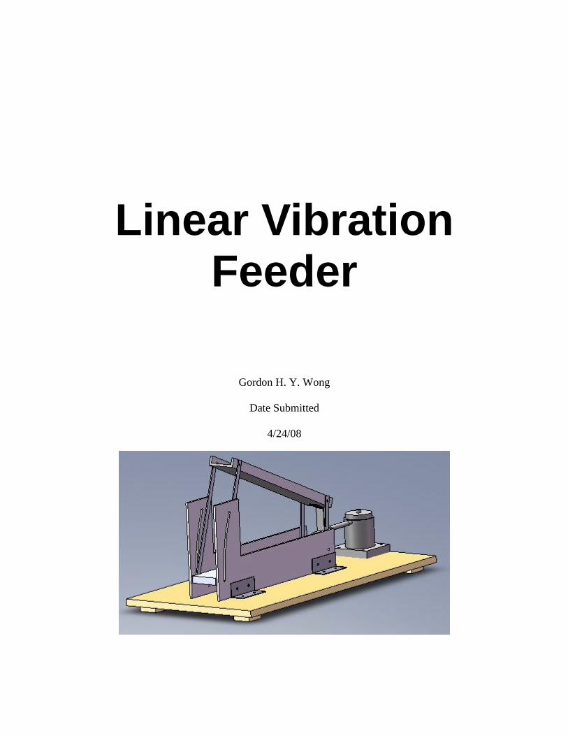
Linear Vibration Feeder
Gordon H. Y. Wong
Date Submitted
4/24/08

Abstract: By altering the angle of a vibration plate and the angle of vibration relative to the
plate, different resulting force can be achieved. A working prototype model is built that
demonstrates the vibration theory though there are limitations due to design.

Table of Contents
Abstract: .............................................................................................................................. 2
Table of Contents ................................................................................................................ 3
Introduction ......................................................................................................................... 4
Background ......................................................................................................................... 4
Methodology ....................................................................................................................... 6
Overall Design Concepts ................................................................................................ 6
Design Process ................................................................................................................ 6
Software .......................................................................................................................... 9
Final Design .................................................................................................................. 10
Prototype Construction Materials ................................................................................. 10
Stock ......................................................................................................................... 10
Screws and Nuts ........................................................................................................ 10
How to build / assemble ............................................................................................ 11
Analysis............................................................................................................................. 13
Results and Discussion ..................................................................................................... 16
Conclusion ........................................................................................................................ 16
Comments ......................................................................................................................... 17
Recommendations ............................................................................................................. 18
Bibliography ..................................................................................................................... 19
Appendix A – Natural Frequency of Load Ramp ............................................................. 20
Appendix B – Solidwork Drawings and Models .............................................................. 22

Introduction This project was specifically designed for professors of Worcester Polytechnic to
have a working model to show students (and others), one of the theories of vibration.
When professors explain a new concept or theory, students might not be able to fully
comprehend how it works or how it might be applied to real life. This is true especially
for those who are visual learners. This project would give students a visual
representation of the vibration theory (that will be discussed in the next section) so that
can aid students in better understand the material.
Therefore, the ultimate goal of this project is to build a working model that
demonstrates how the vibration theory can be applied in real life. A sub-goal would be
have the model should be easy to carry, assemble, use, dismantle, and store.
Background Vibratory feeders are not something new to the industrial world. They have been
used in many industries such as pharmaceutical, mining, and even food. There are 2
main types of feeders, linear and bowl shaped, operating with the same theory. Many of
the industrial shakers come will other fixtures suited to the type of job it has to do.
Screens are used to separate different size particles or to separate out dirt and other
unwanted particles. Other feeders have fixtures that orientate the mediums in a certain
direction in preparation for the next step in the process of manufacturing.
Simplified version of the theory behind the project
An object or particle is placed on a slope. The frictional force(s) prevents the
object from rolling/sliding down the slope. When an external force is acted on the slope,
it will drop down and back. The object/particle will “fall” onto a higher point on slope.
Due to the frictional force(s), the object/particle wouldn’t return to the original point on
the slope. Repeating this will cause the object/particle to “climb” up the slope.
Detailed version –
A vibration feeder with 1-D motion (Figure 1) with the frame attached to the
inclined vibrating plate. Angle α is the angle of the plate relative to the ground. Angle β
is the angle of vibration relative to α (or in other words, the surface of the plate).
Figure 1 – Vibration Feeder

Free flight of the particle would make analysis and the system more complicated.
Thus free flight of the particle is to be excluded. The way to exclude the particle from
free flight with the following equation,
(g / Aω2) * (cos α / sin β) > 1
g = magnitude of gravity
A = amplitude of the acting force
ω = rotational velocity
α = angle of the plate
β = angle of vibration relative to α
Otherwise, two coefficients are important when the particle is in free flight
R = ẏ+ / ẏ–
λ = 1 – ẋ+ / ẋ–
R = restitution coefficient ratio of normal velocities
λ = coefficient of instantaneous friction
The subscripts “+” and “-” refers to values of velocities after and before impact
respectively upon return of the particle onto the plate.
Conditions for positive (thus directed upwards) apparent mean longitudinal
velocity of the particle V if,
tan α ≤ f 2 tan β
α < ρ = tan-1
f
α = angle of the plate
β = angle of vibration relative to α
f = coefficient of friction
V = AωF (Aω2 / g , α , β , f , R , λ) where F is a certain non-dimensional function. Basic
conclusions can be drawn up based on analysis for solutions of equations of motion.
1. For fixed acceleration amplitude Aω2 mean longitudinal velocity V is proportional
to Aω and thus to 1 / ω. There assigning A as high as possible would minimize
the admissible frequency.
2. Increasing Aω2
increases V however this growth becomes small at high Aω2 and β.
3. Growth of V with A at fixed ω has a higher rate than a linear one.
4. Function V(β) has a clear peak for fixed values of all other parameters (being zero
or negative at β = 0 and β = π / 2)
5. Increasing inclination angle α of the plate would decrease V.
6. V decreases with increasing R and λ.

Methodology
Overall Design Concepts
The whole system can be divided into four major parts or subsystems. The first
part is the beam that the material will be transported on (hence forth designated as Load
Ramp). The second is the Support system for the beam (hence forth designated as Load
Ramp Support(s)). The Load Ramp Supports have two jobs. The first is to Support the
Load Ramp and prevent any side forces or movements that might occur. Its second job is
to allow the user whoever he/she might be to change the Load Ramp angle. The next is
the shaker and possibly a system to change its angle of acting. The shaker that is
procured can pivot on its own allowing various angles of acting force thus there were no
need for its own subsystem. The last major subsystem is the base assembly that the rest
of the system rest on.
The first objective for the designing stage is to determine the natural frequency of
the loading beam. This is to ensure that when the system is turned on, the vibration
would not shake at the natural frequency of the Load Ramp. If that situation does occur
then the energy from the vibration not only would just excite the beam and not the
medium, but it could potentially destroy the ramp and the rest of the system. The original
plan was to use steel, aluminum, wood, or plastic. The Load Ramp would have side
Supports to make sure that the materials would not fall off the side and possibly damage
the system.
The medium(s) that will be transported on the Load Ramp will be flat with a large
surface area compared to its thickness (such as coins). This is to prevent a rolling effect
that a spherical-like object will have when the system is turned on.
Design Process
For the Load Ramp and the Load Ramp Support, wood and plastic as a potential
material is eliminated because of the stiffness. Aluminum is chosen as the final material
because of the cost of materials.
The original design for the Load Ramp Support was to have legs as support. It
was scrapped because it only had a set number of configurations allowing only a limited
number of angles that the Load Ramp can be set. The first version of the new Load
Ramp Support is shown in (Figure 2) and (Figure 3) shows it being attached to the Load
Ramp.
Figure 2 – Load Ramp Support 1.0

Figure 3 – Load Ramp Support 1.0 and Load Ramp
Based on further analysis of the system, it is determined that the Load Ramp
would be too stiff to actually vibrate. Thus a linkage system was used (commercial linear
vibration feeders similar to this also use linkages). The lengths of the linkages, Load
Ramp, and Load Ramp Support were determined based on the resulting movements of
the Load Ramp. To determine the final linkage system, four-bars is used (Figure 4). For
full analysis of the four-bar linkage, refer to Analysis section.
Figure 4 – Linkage
Version 2 of the Load Ramp (Figure 5) accommodates the linkage system and
easily allows for Load Ramp to change angles but from a manufacturing point of view,
the T base creates some problem.
Figure 5 – Load Ramp Support 2.0

For the final version (Appendix B Load Ramp Support), angle brackets are used
to attach the supports to the base. The final version of the Load Ramp Support was
determined based on a manufacturing point of view to lower cost of material and ease of
machining.
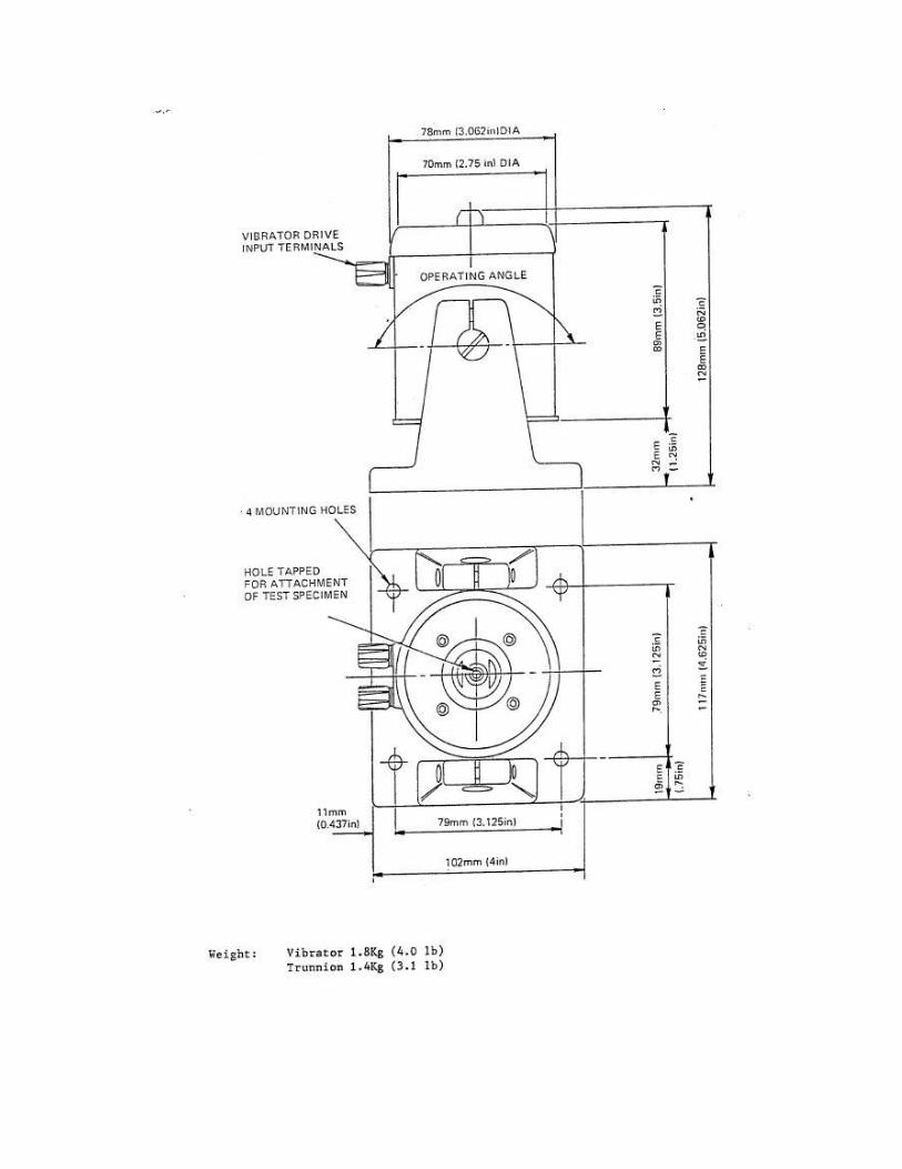
The shaker that was obtained turned out to be able to pivot on its own. Figure 6
below depicts a schematic of the shaker.
Figure 6 – Shaker
This eliminated the need for its own support subsystem which the preliminary
design (Figure 7) had.
Figure 7 – Shaker Support
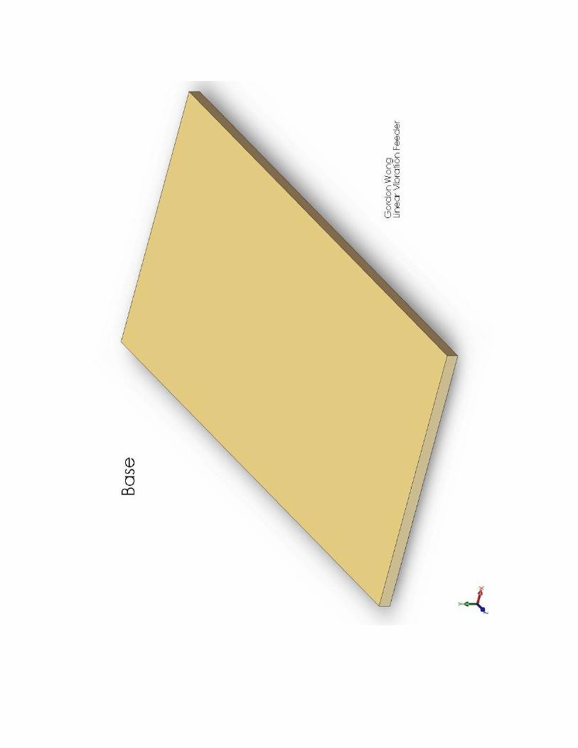
The base subsystem specs were based on the final design to ensure that the base is
large enough and strong enough to ensure that everything fits and wouldn’t collapse.
Also, to make sure that it wouldn’t be too large to create unnecessary weight. Figure 8
below shows the Base Subsystem.
Figure 8 – Base Subsystem

Software
Solidworks is a CAD (computer-aided design) computer program that many
engineers use in the design process. The program creates a 3-D environment where the
user can design and draw either simple parts or complicated assemblies. Solidworks can
also allow the user to “see” how the objects will look and whether the parts will come
together in the way they are supposed to.
FOURBAR is a computer program created by Prof. Norton from Worcester
Polytechnic to analyze a four bar linkage. By altering the lengths of the links and the
angle of freedom, it is possible for the program to “draw out” the resultant actions. Thus,
the user can easily design a linkage with the desired resulting actions without lengthy
calculations or having to build a prototype.
GibbsCam is a CAM (computer-aided manufacturing) computer program created
to aid engineers in CNC (computer numerical control) functions. GibbsCam allows
engineers to program machines to machine their parts.
Mathcad is computer software used for calculating engineering, math, and
scientific problems. It also has engineering units to help ensure that the calculations are
done correctly.
LabVIEW (possibly) (short for Laboratory Virtual Instrumentation Engineering
Workbench) is a computer program created by National Instruments. The user is able to
create a program to acquire, analyze, and output data from measuring instruments.

Final Design
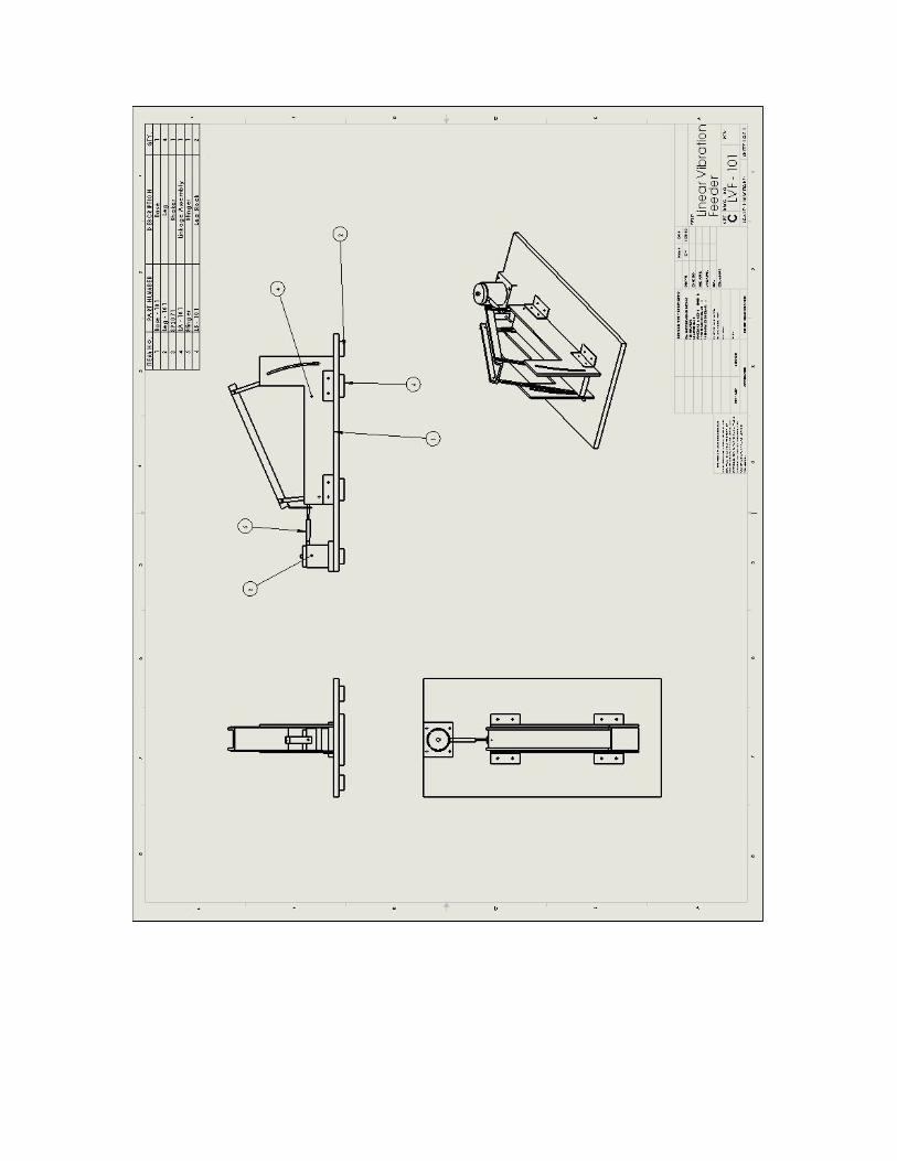
See Appendix B for the final version of the linear vibration feeder designed using
Solidworks.
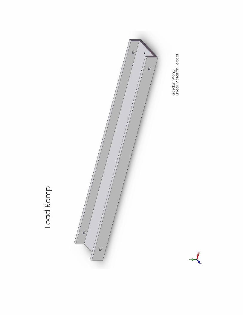
The final version of the Load Ramp was similar to the one in Figure 4 except that
it has a hole at one end for the Link Bracket which connects the Load Ramp with the
stinger from the shaker (Figure 9).
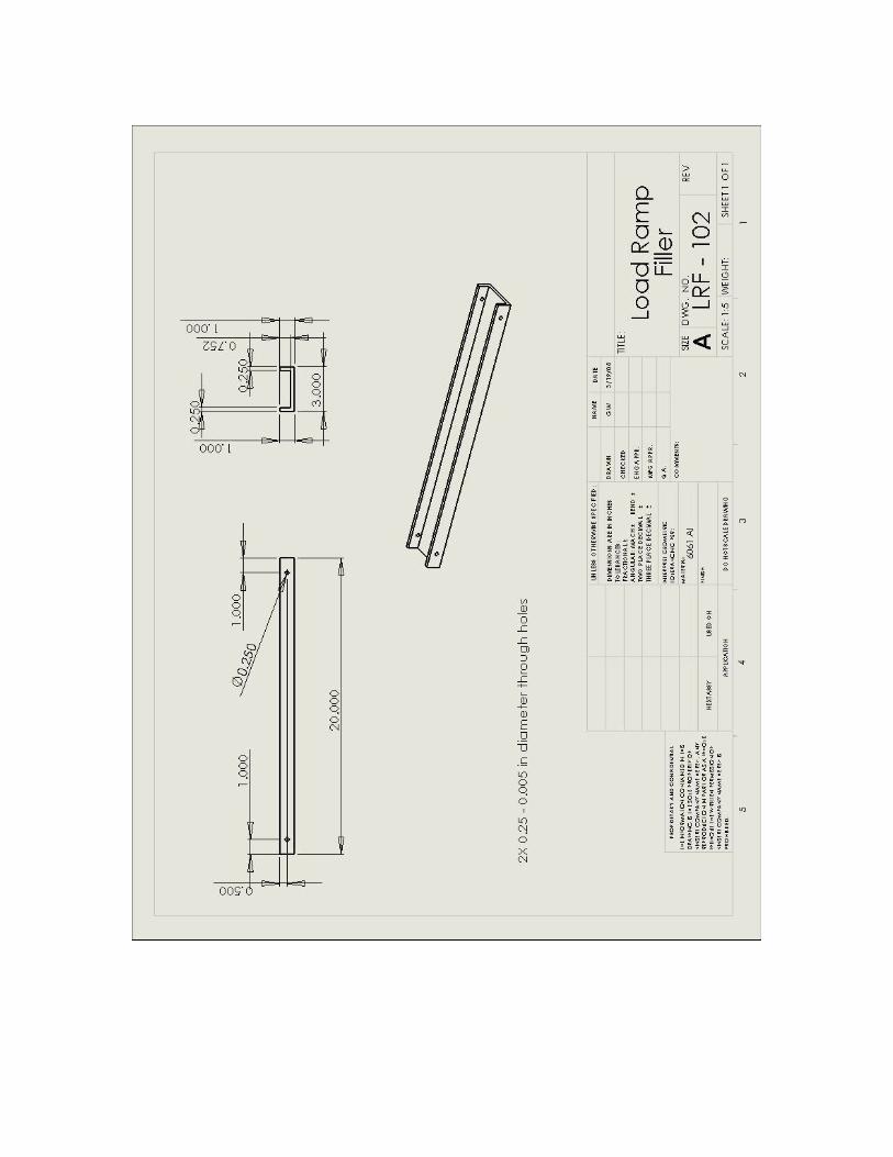
The Load Ramp Filler from Figure was changed to look like the Load Ramp
because there were extra stock to use and the consideration of stock costs.
The Solidworks model showed that the Load Ramp Support is one piece (Figure
10). However, the Load Ramp Support was machined from two pieces because the cost
of obtaining a large square stock is much higher than a long beam. It is held together by
one of the brackets.
Prototype Construction Materials
Stock
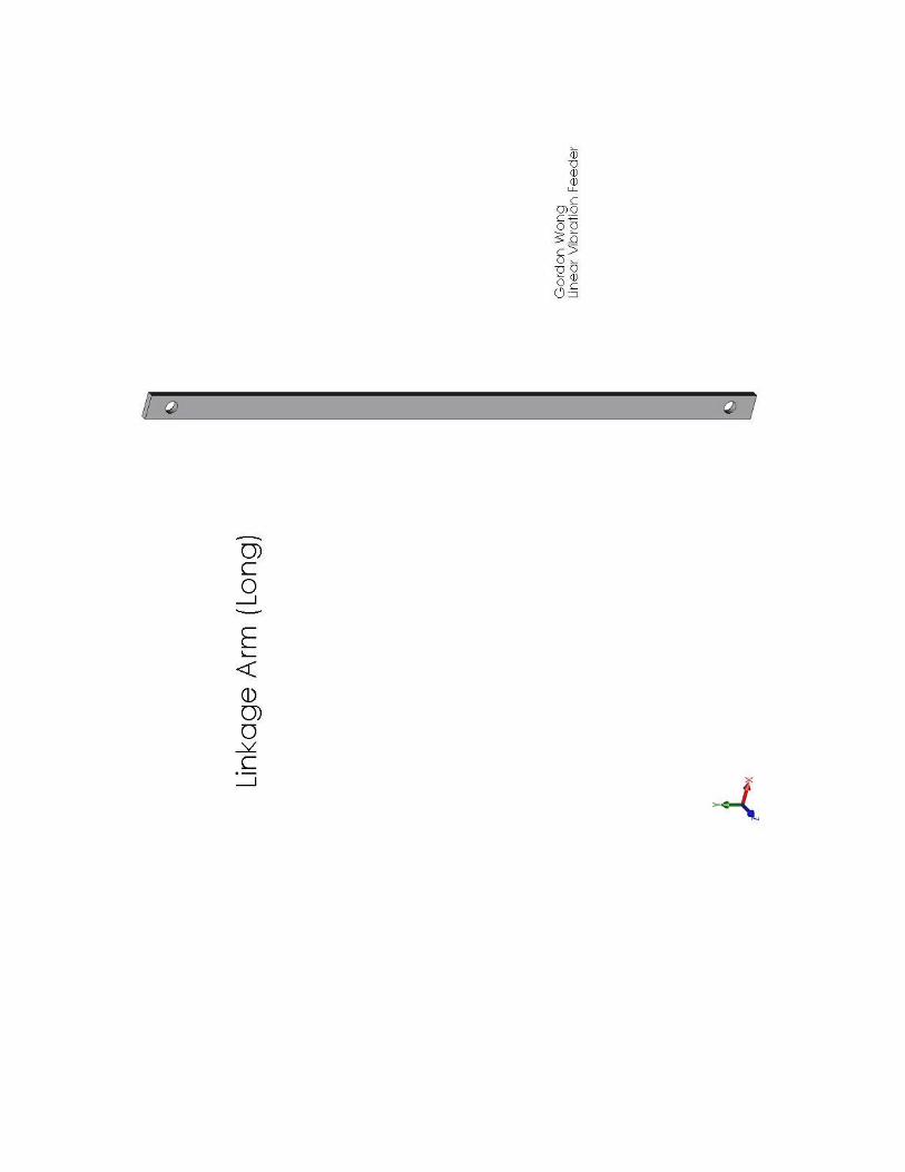
Linkage arms – Multipurpose Aluminum (Alloy 6061), 1/8 inch Thick X ½ inch Width X
6 feet Length
Load Ramp and Load Ramp Filler – Alloy 6061 Aluminum Channel, 1/8 inch Thick, 3
inches Base X 1 inch Leg, 8 feet Length
Angle brackets – High-Strength Aluminum (Alloy 2024), 90 Degree Angle, 1/16 inch
Thick, 1-1/2" X 1-1/2" Leg, 3 feet Length
Load Ramp Support – Multipurpose Aluminum (Alloy 6061), ¼ inch Thick X 4 inches
Width X 6 feet Length
Link between Load Ramp and Stinger – 6061 Al, 0.31 inch Thick X 0.91 inch Thick X 5
inches Length
Screws and Nuts
Steel Shim, w/o Internal Notch, .005" Thick, ¼ inch Inner Diameter, 3/8 inch
Outer Diameter
18-8 SS Precision Phillips Shoulder Screw, ¼ inch Shoulder Diameter, 3/8 inch
Shoulder Length, 10-32 Thread
18-8 SS Precision Phillips Shoulder Screw, ¼ inch Shoulder Diameter, 1/2 inch
Shoulder Length, 10-32 Thread
Zinc-Plated Steel Machine Screw Nut 6-32 Screw Size, 5/16 inch Width, 7/64
inch Height
Acetal Hex Nut, 10-32 Screw Size, 3/8 inch Width, 1/8 inch Height
Zinc-plated Steel Flat Head Philips Machine Screw, 6-32 Thread, 1 inch Length
Wood Screw 6-32 Thread, 1 inch Length

How to build / assemble
Linkage –
1. Place a shim between the Load Ramp and Linkage arms
2. Thread a shoulder screw through the hole from the Load Ramp side
3. Secure screw with hex nut and tighten
4. Secure link between Load Ramp and Stinger (Figure 9)
Figure 9 – Load Ramp attached to Linkage Arms
Linkage Support –
1. Line up the Support plates
2. Secure them together using an angle bracket with a machine screw and hex nut
3. using more screws and hex nut to secure another Angle Bracket to the Support
(Figure 10)
Figure 10 – Supports held together
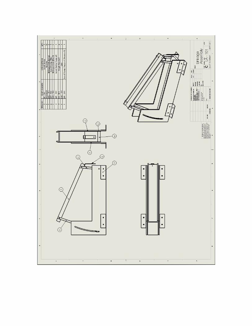
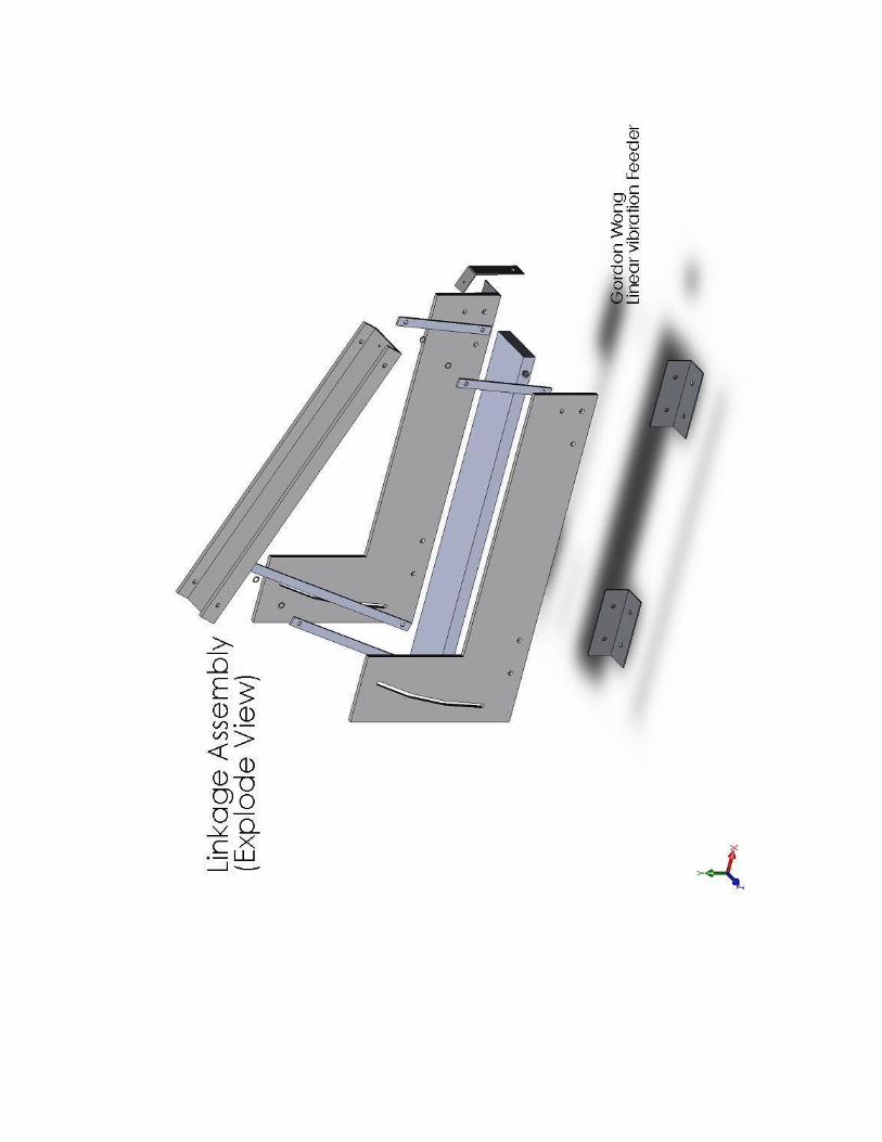
Linkage Assembly –
1. Thread the (longer shoulder length) shoulder screw through Filler, Linkage Arms,
and Support)
2. Secure with a hex nuts (Figure 11)

Figure 11 – Linkage Assembly
Final Assembly –
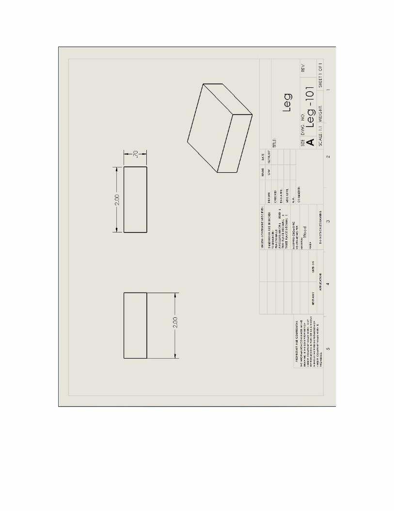
5. Screw the Legs to the Base using wood screws (Figure 12) The Legs are 1 inch
inward in each direction to give more surface area for hand grips and to decrease
the chance of splinters to the wooden legs.
Figure 12 – Base Support
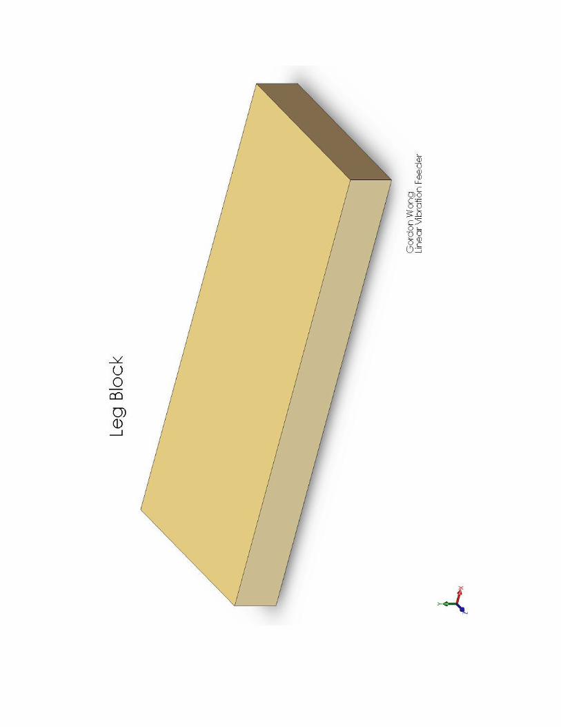
6. Line up the Angle Brackets to pre-drill holes on the bases secure using the wood
screws having already line up the Leg Block (the Leg Block is to ensure that the
wood screws doesn’t stick out)
7. Secure link between Load Ramp and Stinger
8. Attach Stinger to Link
9. Secure Shaker to Base (Figure 13)
Figure 13 – Finished Assembly

Analysis Linkage Analysis –
To design the linkage system, first the software FOURBAR (Figure 14) is used.
This software helps analyze the motions based on inputs in the yellow box in figure
below.
Figure 14 – FOURBAR Linkage Design
First, the type of resulting motion that the linkage will have is required. The
linear vibration feeder should have a linear motion with a little loop at the end like the
one from Figure 15 (in green).
Figure 15 – Desired Linkage motion
Using Figure 3-21 in Design Machinery by Prof. Norton as reference, the
approximate length of the desired linkages was achieved. Based on the raw numbers,
some manipulations and iterations were used to determine the final numbers. Thus
linkage system is designed. The lengths of the links, Load Ramp, and Load Ramp Filler
are based on this design. Crank (5 inches) is equal to the short linkage arm, coupler (16
inches) is the Load Ramp, rocker (12 inches) is the long linkage arm, and distance to

coupler point (18 inches) is the Load Ramp Filler. The distances between the holes in
these parts were based on these lengths.
Load Ramp Analysis –
In determining the natural frequency of the load Ream (to avoid), the Shock and
Vibration Handbook by Harris and Crede is used. Figure 16 shows the type of beam that
the Load Ramp is similar to. The equation for the natural frequency is
ω = A * √ [(E * I) / (μ * L4)]
ω = rotational velocity with units [rad / sec] which can be converted to Hz by 2π
A = coefficient of the beam (depends on the parameters)
E = modulus of elasticity of material with units [lbf/in2]
I = area moment of inertia with units [in4]
μ = mass density of material with units [(lbf * sec2) / in
2]
Figure 16 – Hinged-Hinged (simple) Load Ramp
A is given in the Shock and Vibration Handbook as 9.87 for a Hinged-Hinged
(simple) Load Ramp. Hinged-Hinged means that the beam is supported on both ends.
Simple means that the beam only has one wave traveling through it at one time.
E is modulus of elasticity of materials that could be found in various engineering
textbooks or handbooks. The modulus of elasticity for aluminum is 1.04 * 107 lbf / in
2.
I is the area moment of inertia. For simplification, the Load Ramp is considered
only as a square beam without the sides. The equation for area moment of inertia for a
square beam is,
I = (b * h3) / 12
I = area moment of inertia with units [in4]
b = base of the beam with units [in]
h = height of the beam with units [in]
In this case b is equal to 3 inches (width of the beam) and h is equal to 1/8 inch (thickness
of the beam. Thus, I comes out to 4.883 * 10-4
in4.
µ is the mass density of the material with units of (lbf * s2) / in
2. The equation to
solve of µ is,
µ = (A * γ) / g

μ = mass density of material with units [(lbf * sec2) / in
2]
A = cross sectional area of the beam with units [in2]
γ = weight density of the material given in engineering textbooks with units
[lbf / in3]
g = gravity constant with units [in / s2]
The cross sectional area is then 3 in * 1/8 inch = 0.375 in2. γ is given as 0.10 lbf / in
3 in
the Machine Design textbook by Prof. Norton. Gravity on Earth is 386.089 in / sec2.
Thus, µ comes out to 9.713 * 10-5
lbf * s2 / in
2.
L is the length of the beam which is 2 feet in this case based off the linkage design
analyzed early in the report.
Calculations were done using Mathcad. See Appendix A for the Mathcad file.
Based on analysis of the simple beam, the natural frequency of the beam when it is 2 feet
long is 30.975 Hz. Thus frequency at about 31 Hertz should be avoided.

Results and Discussion Results from accelerometer? Results within expectations? Results outside
expectations
Conclusion The demo works within the specifications of the theory. Thus this system
demonstrates that the theory is valid. The particle moves up the Load Ramp with varying
combinations of angle α and β. In the current configuration and surface, the greatest
resulting acceleration is X with α being X° and β being X°.

Comments This had been an interesting project to work on. This project applies several
classes’ worth of material into real life. Also, there was a need to seek outside help and
learn about things that aren’t taught in class. This project “forced” me to think more like
a mechanical engineer working in a company rather than a student working on another
class project.
I would like to thank Professor Cobb and Professor Dimentberg for letting onto
this project and their patience into completion of this project. I would also like to thank
the personal at the manufacturing lab for their time and aid into helping make the demo.
Without their help, this project would not have reached completion.
As engineers, “mistakes” are made no matter how careful the planning stages are.
After the assembly is finished, there were several problems that could have been avoided.
The geometry of the linkage system was not fully addressed. As such, the Load Ramp
would be at angle of 24° when the Load Ramp Filler is at 0° and the short linkage arms
are vertical. Also the hex nuts would hit the Supports in wide motions limited the range
that the system could operate at.

Recommendations One of the variables in the theory is the coefficient of friction. Too much friction
and the medium(s) being carried wouldn’t move much, while too little friction would
cause the medium(s) to simply/roll slide down. By changing the coefficient of friction
(via changing the surface either by materials or finishes), it is possible to achieve the
optimal result. Tests should be done to find this optimal result based on the surface
material or finishes possibly in combination with varying angles and thrust amplitude.
Design of solid models using Solidworks (and other CAD software) should also
take the manufacturing stage into consideration. Making the model extrude in either
direction might be easy but when it is imported to CAM software(s) like GibbsCAM, it
could create extra steps to maneuver the model to the right orientation for machining.
When designing a part or assembly, try to find tools and parts that could be used. If the
tool or part is not available, then it might be required to alter the model slightly to
accommodate for this. Otherwise, there will be trouble when the manufacturing parts.
When modeling a piece, whole numbers or simple fractional numbers are easy to
use. However, in reality, the work stock and design have tolerances that could determine
whether something is held the way it is suppose to or if there is interference. Machined
holes are not 100% to specification due to defects and burrs in the stock. Design and
tolerances should take machining into account. Warping of pieces during machining
could happen especially for long flexible thin strips like the longer linkage arm.
Fine-tuning the linkage system design would provide a more optimal resulting
acceleration of the system. Also, the frictions and clearance between the parts could be
altered to increase the velocity of the particle(s) / medium(s) being transported.
The steel shims or spacers should be longer to increase the distances between the
different pieces thus to decrease possible interference when the system is in motion. Also
this would prevent the hex nuts from hitting the Support in wide motions.
Things like bolts and screws should always be checked and updated with the
design to ensure that the size is correct. Also, extra stock is important in case something
goes wrong with the piece. Always double check everything and re-probe CNC tools
prior to every usage.

Bibliography
Harris, Cyril M. and Crede, Charles E. Shock and Vibration Handbook Fourth Edition.
New York: McGraw-Hill 1996.
Norton, Robert L. Machine Design: An Integrated Approach Third Edition. Upper Saddle
River, NJ: Pearson Prentice Hall 2006.
Norton, Robert L. Design of Machinery: An Introduction to the Synthesis and Analysis of
Mechanisms and Machines Fourth Edition. New York: McGraw-Hill 2008.
Blekhman, I.I., Dzhanelidse, G.Iu. "Vibrational Displacement" (M. Dimentberg, Trans.).
Moscow, Nauka, 1964

Appendix A – Natural Frequency of Load Ramp
Acanti 9.87 Coefficient for Hinged-Hinged (simple) (Harris, Shock and Vibration
Handbook. 1996. Page 1.13)
g 386.089in
s2
Gravity Constant on Earth
g 32.174ft
s2
Gravity Constant on Earth
Material Data of Aluminum
aluminum 0.10lbf
in3
Weight Density of aluminum (Norton, Machine Design. 2006. Table C-1
p.944)
aluminum
aluminum
g Mass Density of aluminum
aluminum 2.59 104
lbf s
2
in4
Geometry Assumptions
bbeam 3in (Width of the beam)
hbeam1
8in (Thickness of the beam)
Abeam bbeam hbeam Cross Sectional Area of Beam
Abeam 0.375 in2
Area Moment of Inertia for rectangular prism (Norton, Machine
Design. 2006. Appendix B p.942) Ibeam
bbeam hbeam3
12
Ibeam 4.883 104
in4
Lbeam 12in 13in 48in Various Length of Beam (1foot to 4 feet with 1 inch increments)

For Aluminum:
Ealuminum 1.04 107
lbf
in2
Young's Modulus for aluminum (Norton, Machine Design. 2006.
Figure 2-17 p.52)
Ealuminum 1.04 107
lbf
in2
aluminum
Abeam aluminum
g Mass Density of Aluminum per Unit Length of Beam
aluminum 9.713 105
lbf s
2
in2
naluminum Lbeam Acanti
Ealuminum Ibeam
aluminum Lbeam4
naluminum Lbeam 495.603
422.289
364.117
317.186
278.777
246.944
220.268
197.692
178.417
161.83
147.452
134.909
123.901
114.187
105.572
...
Hz
naluminum 48in( ) 30.975Hz

Appendix B – Solidwork Drawings and Models
The following pages are a compilation of final versions of Solidwork drawings,
and models (of individual parts and assembly).
The stinger and the shaker are not shown because the objects haven’t been
physically seen. The model drawing of the shaker is taken from the manual that the
shaker comes with.