linear ripples and traveling circular ripples produced on polymers by thermal afm probes
TRANSCRIPT
Linear ripples and traveling circular ripples produced on polymers by thermal AFM probes
Enrico Gnecco,1,*,† Elisa Riedo,2 William P. King,3 Seth R. Marder,4 and Robert Szoszkiewicz5,*,‡
1Department of Physics, University of Basel, Klingelbergstrasse 82, 4056 Basel, Switzerland2School of Physics, Georgia Institute of Technology, Atlanta, Georgia 30332, USA
3Department of Mechanical Science and Engineering, University of Illinois Urbana–Champaign, Urbana, Illinois 61801, USA4School of Chemistry and Biochemistry, Georgia Institute of Technology, Atlanta, Georgia 30332, USA
5Department of Physics, Kansas State University, Manhattan, Kansas 66506, USA�Received 19 February 2009; revised manuscript received 8 May 2009; published 18 June 2009�
We discuss the time and temperature evolution of the nanometer-scale surface undulations �ripples� pro-duced by a heated atomic force microscope �AFM� tip scanning across surfaces of several amorphous poly-mers. During linear zigzag scanning we obtain pseudolinear ripples approximately perpendicular to the fastscan direction in a range of scan rates and probe temperatures. As expected, the size of the ripples increasesmassively in the vicinity of the glass temperature for each polymer. We also examine a different case in whichthe AFM tip follows a circular path. Contrary to the “steady” linear ripples we obtain circular ripples whichrotate along the scanning path during consecutive scans. The group velocity of the circular ripples is 2 ordersof magnitude lower than the scan speed. We interpret the experimental data using a phenomenological modelaccounting for erosion and smoothing effects caused by the probing tip.
DOI: 10.1103/PhysRevB.79.235421 PACS number�s�: 81.16.Nd, 82.35.Gh, 07.79.Lh, 45.70.Qj
I. INTRODUCTION
The formation of ripple patterns on fragile surfaces sub-ject to external perturbations occurs commonly over a rangeof length scales. Macroscopic linear ripples with wave-lengths between several centimeters and several meters areoften created by wind on sandy deserts and sea shores.1,2
These ripples arise from interactions of high-energy long-leaping sand grains with the low-energy short-leaping grains.Similar to sand ripples, ion sputtering experiments on metalsubstrates �such as argon sputtering on Ag� have producedmicroripples with wavelengths ranging between tens of na-nometers to submicrometers.3 It has been shown that theproperties of the incident ion beam and the properties of thebombarded surface lattice determine the shape and orienta-tion of these microripples. Finally, nanoripples with wave-lengths between several tens of nanometers and hundreds ofnanometers have been obtained by scanning a substrate withan atomic force microscope �AFM� tip. Nanoripples havebeen observed after many subsequent zigzag scans over thesame micrometer-size areas of polymers,4–9 ionic salts,10
metals,11 and semiconductors.12 Nanoscale ripples on poly-mers have been produced in just one AFM scan using eithera heated polymer surface13 or a heated AFM probe.14,15
These ripples are approximately linearly shaped and alignnormal to the AFM fast scanning direction.
The evolution of sand macroripples and ion-sputtered mi-croripples is usually described by complicated fourth-orderdifferential equations, which take into account competitiveprocesses of surface erosion and relaxation.16,17 In contrast,nanoripples produced by repetitive localized scanning haveonly been interpreted using simplified and qualitative mod-els. In the case of polymers, these models relate the evolu-tion of ripples to polymer properties alone,9,18 local cracksformation and subsequent polymer peeling,19 or minusculewearing off the surface during each scan.20 Even less isknown for nanoripples produced on polymers using heat.
Clearly, the heat changes compressive and tensile stresses ina substrate due to poking it with an AFM tip but a quantita-tive interpretation is still elusive. Furthermore, the experi-ments and models have been limited to linear ripples; how-ever, an enhanced repertoire of ripple geometries, such ascircular ripples, could lead to more diverse applications, e.g.,templates21 for custom nanosorting or nanoassembly andstructures for nanoplasmonics and nanoptics.22–26
Here, we investigate the ripples created on several poly-mer films by a resistively heated AFM probe under a rangeof scanning conditions. We start by establishing a firm con-nection to the previously published results. Thus, we producethe pseudolinear ripples at several heating conditions andscanning speeds. We find massive enhancement of linearripple wavelengths in proximity of the glass temperature,which is consistent with previous investigations. Next, weinvestigate a case in which a heated AFM probe follows acircular path rather than a typical zigzag path. Circular scan-ning produces circular ripples aligned along the scannedpathway. Circular ripples tend to rotate along the scan direc-tion and thus are far more dynamic than pseudolinear ripples.We measure their group velocity and we reproduce their evo-lution in silico by introducing a phenomenological modelbased on interplay between surface erosion and surface re-laxation.
II. EXPERIMENTAL
In our AFM experiments we used resistively heatedprobes �rh levers� �Refs. 27–29� in the contact mode withdifferent polymer samples: a poly�methylmethacrylate��PMMA, Mw�120 kD�, a polycarbonate �PC, Mw�20–25 kD�, and a polysulfone �PSul, Mw�44–53 kD�.Polymer powders �Sigma-Aldrich, USA� were dissolved intoluene and spin coated on a nanorough glass substrate�Fisher Scientific, USA� to yield �1-�m-thick polymerfilms. The rh levers were custom mounted in a Multimode
PHYSICAL REVIEW B 79, 235421 �2009�
1098-0121/2009/79�23�/235421�7� ©2009 The American Physical Society235421-1
IVa AFM �Veeco, USA� designed for a zigzag surface scan-ning and equipped with a homemade module for a circularsurface scanning. Our AFM uses a standard laser-beambounce-detection scheme for sensing the cantilever deflec-tion.
We obtained a tip-polymer temperature profile based onthe thermal calibration of the rh levers28 and a finite-elementsteady-state solution of the heat-transfer equation from a can-tilever to a polymer surface.30 We supposed that heat transferfrom the rh lever to the polymer surface occurs mostly byconduction through a tip from an area just above the tip.28
We used typical thermal properties of the polymers as well astypical dimensions and thermal properties of the rhlevers.15,28,31
III. RESULTS AND DISCUSSION
A. Linear ripples
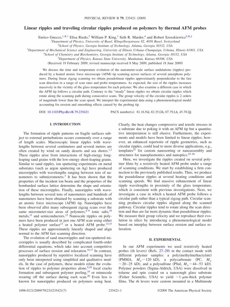
Figure 1�a� shows a few examples of 1�1 �m2 AFM
images of pseudolinear ripples obtained �i� at room tempera-ture, �ii� in the vicinity of the glass transition temperature,Tg, and �iii� above Tg. A flat polymer surface is modifiedduring one AFM scan giving rise to a very regular patternwhen the local surface temperature is close to the character-istic Tg of the polymer. Once the surface temperature isgreater than Tg the patterns can be chaotic and the quasilineararrangements of the ripples is often lost. By autocorrelatingeach of the AFM images, we find the characteristic wave-length of the ripples, �, for each investigated temperatureand scanning speed. In Fig. 1�b� we plot the obtained auto-correlation lengths versus estimated local temperature foreach substrate. Below Tg the corresponding � remains in theorder of 100 nm for each polymer. Above Tg the value of �increases abruptly in an exponential-like fashion.
The sudden increase in the wavelength � beyond the glasstransition temperature Tg has already been reported and usedto estimate the value of Tg for some polymer samples.14,32,33
Similar to our results, Ref. 13 reported ��100 nm belowthe polymer Tg while repetitively scanning preheated poly-styrene films with regular AFM cantilevers. However, theripples obtained by repetitive scanning grew linearly withtemperature at T�Tg, which is in contrast to the exponentialincrease we observe. We qualitatively explain our data andthis controversy using continuum contact mechanics.34,35
The critical normal force, Fc, exerted by a stiff AFM tip atthe tip-polymer contact and at the onset of plastic deforma-tion, is proportional to the plastic yield stress, �c, and thecontact area, Ar :Fc=�cAr. Due to the extensive complianceof polymers, the value of Ar is essentially determined by thetip profile and thus related to the ripple wavelength, �. De-scribing the tip as a cone with an opening angle �, we esti-mate ��2�� tan �+R�; here � is the indentation depth and Ris the AFM tip curvature radius. We have supposed that �i�on the sides of an indent � the polymer adjusts to the tipshape � tan � since polymer is soft and the tip can penetratedeeply and �ii� the edges of an indent are shaped correspond-ingly to the tip radius R since the tip will move around themback and forth in the zigzag scans. The tip is symmetric so itcomes as a factor of 2. Due to large indentation depths weneglect the tip-sample adhesion energy and ��Ar /R.34,35
Furthermore, we assume elastic-plastic contact area bound-ary and obtain a final estimate: ��2�3.2Fc tan � / ��cR�+R�.
Phenomenologically, it has been shown that for unori-ented macroscopic polymer films the value of �c decreaseslinearly with temperature up to the glass transition tempera-ture, and past Tg, the value of �c starts to decrease exponen-tially with temperature.36 Assuming that �=30°, R=20 nm,Fc=30 nN, and �c=1 GPa �typical for many unorientedpolymers such as PS or PMMA�, we get ��50 nm at roomtemperature. Just above the glass transition temperature �chas been reported to drop by 50–90 %,36 which yields muchlarger values of � �consistent with our data�. Furthermore, atthe macroscopic scale Ref. 36 reported that �c is linearlydependent on the temperature above Tg if the polymer hasbeen prestretched. This is likely the case reported in Ref. 13,where the sample was scanned many times and globallyheated.
Figure 1�b� shows that a slower scanning speed producesa faster rate of � increase with temperature. Solutions of
a)
b)500
400
300
200
100AutocorrelationLength(nm)
25020010050Estimated Sample Temperature (oC)
PMMA@ 0.5HzPMMA @ 2Hz
Tg(PMMA) = 114 C
PC @ 0.5HzPC @ 2Hz
Tg(PC) = 150 C
PSul @ 0.5HzPSul @ 2Hz
Tg(PSul) = 220 C
o
o
o
150
FIG. 1. �a� 1�1 �m2 AFM contact-mode images of ripplescreated by rastering polymer films �spin coated on glass substrates�with a resistively heated AFM probe at several temperatures. �b� Aplot of the autocorrelation lengths obtained from �a� reveals an ex-ponential growth of the ripple wavelengths with temperature. Dataobtained for 0.5 Hz �fitted with broken lines� and for 2 Hz �fittedwith solid lines� scanning speeds are presented for each polymer.
GNECCO et al. PHYSICAL REVIEW B 79, 235421 �2009�
235421-2

heat-transfer equations for our rh levers show that the steadystate, and thus, stabilization of the temperature at the tip-sample interface, is reached within several microseconds.15
Thus, there is enough time to reach thermal equilibrium ineach one of the 256 AFM data points acquired at 0.5 and 2Hz scan rates for each scan pass. A faster increase in theautocorrelation length at a lower scanning speed displayssome relations to the time-dependent viscoelastic and plasticdeformations of the polymer surface.13
B. Circular ripples
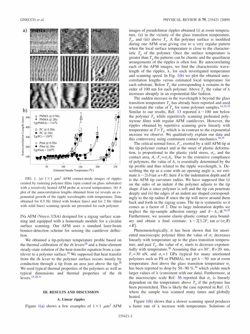
Having examined the linear ripples, we proceeded toscratch a polymer surface in a circular way. Figure 2 shows afew contact-mode AFM images taken after several consecu-tive circular scans of the PMMA sample with a tip heated invicinity of the corresponding Tg. The ripples created within acircumference of the scanned circles are clearly distinguish-able.
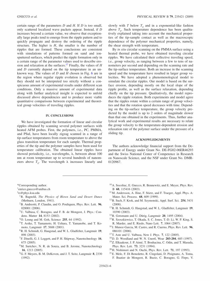
To investigate in situ formation of circular ripples ingreater detail, we have recorded instantaneous variations inthe vertical displacement of the cantilever while scanning aPMMA surface with only minimal AFM feedback. We inves-tigated several temperatures and two different scanningspeeds. After binomial smoothing �Igor Pro, Wavemetrics,USA�, the recorded cantilever displacement follows a pseu-dosinusoidal function with visible undulations �Fig. 3�.These bumpy undulations correspond to major ripples, whilethe pseudosinusoidal background reflects the cantileverbuckling while forced to follow a circular path instead of alinear zigzag path.
We can trace the position of individual ripples during con-secutive scans. By following the same maxima �or minima�over many scanning cycles, it appears evident that the ripplescan move during consecutive scans in a similar manner as awave packet travels in space, and thus, we can calculate theircorresponding group velocity. Figure 4 shows the position ofall the detected maxima in each period vs time. For eachmaximum, the position is measured with respect to the samearbitrary circular angle. When the ripple position overcomes360°, the ripple reappears at 0° similar to the case of periodicboundary conditions.
While scanning with a nonheated cantilever �Fig. 4�a�� wehave initially noticed an irregular progression of the ripples.However, after several cycles �around t�40 s�, a few given
ripples begin to be collectively displaced. The circumferenceof a scanned circle was 1.10.1 �m and the scanning ratewas 0.510.01 Hz. By calculating the slopes of the curvesin Fig. 4�a�, we obtain group velocities ranging between 5and 8 nm/s, i.e., up to 0.015 times the cantilever scanningvelocity.
In Fig. 4�b� we increased the temperature at thecantilever—sample interface �by heating rh levers� to45 °C15 °C �still below the Tg of PMMA, i.e., about115 °C�. We observed that several ripples moved with groupvelocities between 5 and 8 nm/s. Figures 4�c� and 4�d� wereobtained at different positions on the sample but still at thetip-sample interface temperature of 45 °C15 °C. Initially,the ripples travel with typical velocities between 5 and 13nm/s �or 0.024 times the cantilever speed�. After some cycles�about 20–30 scans� they slow down, e.g., to velocities0.5 nm /s on Fig. 4�d�.
We discuss the decrease in group velocity in the nextsection �based on our model�. Here we mention, however,that such a decrease with time might also be affected by drift.We associate vertical or, respectively, lateral drifts with allthe time-dependent processes �such as cantilever, sample,and AFM piezo creeps�, which change the normal force�load� or, respectively, provoke departures from circularscanning. Along with the vertical cantilever position change�presented in Fig. 4� we have recorded �not presented here�the friction signal between the sample and the tip �the so-called “LFM” or lateral force microscopy signal�. The fric-tion signal scales with the normal force. Thus, at a givenload, the mean friction signal �averaged over a period ofcircular ripples� is a good indicator of vertical drift. For the
FIG. 2. AFM images �contact mode, topography signal� of threedifferent circular ripples created by a resistively heated AFM tip. Animage on the left is 410�410 nm2, in the middle is 445�445 nm2, and on the right 375�375 nm2. All images have beenobtained after only a few circular scans with a hot rh tip. Peak tovalley distances are around several nm.
0.7
0.6
0.5
0.4
0.3
5000040000300002000010000
0.76
0.74
0.72
0.70
200001800016000
Initial approach to a surface
CantileverDeflection(arb.units)
Point number (in time)
Close-up
FIG. 3. �Color online� The formation/migration kinetics of cir-cular ripples is obtained from direct acquisition of a cantilever de-flection signal while rastering a heated AFM probe in a circularfashion. To localize the onset of ripple formation we start to recordthe cantilever deflection �most oscillating curve, red online� aheadof a tip-polymer first contact. Superimposed on the raw deflectiondata are smoothed deflection data �blue online, binomial smoothing,Igor Pro, Wavemetrics, USA�. An undulated quasisin wave functionappears after smoothing the deflection data, as depicted on the clo-seup of the initial portion of the deflection data �figure inset�. Afitted sinusoidal wave function is showed in black as well. Undula-tions correspond to the most pronounced ripples �protrusions�created/moved during each period of tip scanning.
LINEAR RIPPLES AND TRAVELING CIRCULAR RIPPLES… PHYSICAL REVIEW B 79, 235421 �2009�
235421-3

data reported in this paper, we have not observed any changein a mean friction over the measurement times. Furthermore,careful analysis of AFM topographs presented in Fig. 2shows that the measured width of the ripples is within theapproximated value for the elastic-plastic indentations at ourexperimental conditions. Thus, any lateral drift is likely be-low our detection limit.
Finally, Figs. 4�e� and 4�f� show traveling circular ripplesat temperatures around and above the PMMA Tg and at a10� larger scanning speed �10� larger circumference, thesame period� than before. In Fig. 4�e� the tip-sample tem-perature has been calculated to be 125 °C20 °C, which isaround the PMMA Tg. The mean group velocity of theseripples ranges between 120 and 190 nm/s, i.e., 0.020–0.034times the cantilever speed. In Fig. 4�f� the tip-sample tem-perature is 175 °C20 °C and the group velocity of thecircular ripples ranges between 150 and 200 nm/s, i.e., be-tween 0.026 and 0.036 times the cantilever speed. In bothcases, the group velocities slow down with time.
Our results show that the circular ripples are created andmoved collectively in a range of group velocities, which �i�are 2 orders of magnitude slower than the tip scanning speedand �ii� can decrease with time. These group velocities, how-ever, increase with the temperature of the tip-sample inter-face as well as with the scanning speed. Curiously, groupvelocities around and above Tg �Figs. 4�e� and 4�f�� are com-parable to the typical migration speeds of sand dunes, suchas sand dunes in Leba, Poland moving at 3 m/yr, e.g., about100 nm/s.
C. Phenomenological interpretation
We start to discuss our results with the case of the circularripples. We consider a circle of radius R lying on a flat areaand select L points, equally spaced along the circle, as wellas 2L side points on two concentric “auxiliary” circles, asshown in Fig. 5. The first circle is then repeatedly scannedclockwise �N times� by an ideal tip. While scanning, the tipmodifies the surface, which is much softer than the tip itself.In our model, we assume that the evolution of the surfacetopography depends on its slope along the scan path. Due todirectionality of the tip motion, we assume that the profilegrows in the presence of a negative slope, decreases withpositive slope, and remains unchanged for a flat surface.
The profile evolution is parametrized as follows. At eachof the L points, the height, z, can �i� decrease by a fixed valueH �in the units of height uz� with a probability p− and �ii�increase by H with another probability p+. The quantities p�
depend on the local slope z�, according to the formulas
p� =1 tanh�2z��
2. �1�
The values p− and p+ are between 0 and 1, and the slope z� issimply estimated by the height increase between the selectedlocation and the next first neighbor in the scan direction.When the profile is flat p−= p+ whereas p−� p+ �or p− p+�when the slope z� is positive �or negative�. The parameter Hcan be interpreted as the erosion rate of the surface scratchedby the tip.
The variation in the height z is immediately compensatedby a smoothening process similar to the one described inRef. 20. The height z�� � of the site ��� is increased by thequantity
a) b)
0.8
0.4
0.01006020 time (s)c)
0.8
0.4
0.080604020
time (s)d)
0.8
0.4
0.01006020
time (s)e)
0.8
0.4
0.010020
time (s)f)
0.8
0.4
0.015050
time (s)
0.8
0.4
0.015050
time (s)
Normalizedposition
Normalizedposition
Normalizedposition
Normalizedposition
Normalizedposition
Normalizedposition
60
FIG. 4. Following the maxima �or minima� of the undulations,superimposed to a quasisin wave function in Fig. 3 during eachcircular scan, provides for the migratory pattern of circular ripples.Here, we detect maxima within the undulations and plot their nor-malized position �within a circular period� vs time. �a�–�d� corre-spond to 0.560.05 �m /s AFM tip velocity and �a� room or �b�–�d� 4515 °C tip-sample interface temperature; �e�–�f� areobtained with 5.60.5 �m /s AFM tip velocity and for �e�12520 °C or �f� 17520 °C tip-sample interface temperature.
FIG. 5. The scan path used to form ripples �intermediate circle�together with two concentric auxiliary circles. The big black dotrepresents the location where the process described in the text oc-curs. This dot is surrounded by four first neighbors and four secondneighbors �empty dots represent the latter�.
GNECCO et al. PHYSICAL REVIEW B 79, 235421 �2009�
235421-4

�z = D��1st
z
6+ �
2nd
z
12− z� � ��uz,
where D is a surface relaxation coefficient and the sums areextended to the first and second neighbors of the selectedlocation ���, defined as in Fig. 5. At the same time, theheights at the first and second neighbors are decreased in thequantities �z /6 and �z /12, respectively. The values 6 and 12are chosen to keep the total “mass” of the polymer constantand to enhance the smoothening effect at the first neighborscompared to the second ones. Thus, a small bump �or depres-sion� is created when the tip moves downward �or, respec-tively, upward�. The height or depth of these features is de-termined by the erosion and relaxation coefficients H and Dand by the local topography.
Under these assumptions, however, the amplitude of thescanned profile would increase without limits. This non-physical result can be prevented by assuming that the curva-ture of the profile cannot exceed the tip curvature R−1. Forthis reason, we estimate the second derivative z� of the sur-face profile along the scan direction and impose the con-straint z�R−1 in our calculations. More precisely, wecould have assumed z� / �1+z��3/2R−1 but it does notchange our qualitative conclusions. We obtain consistencywith other results �see below� assuming that z�max=50uz /ut
2, where ut is the length unit along the circumfer-ence.
Figure 6�a� shows the results of a simulation correspond-ing to D=0.5, H=10, L=150, and N=1000. A pattern of 13circular ripples is formed. For comparison, a pattern ofpseudolinear ripples produced with a similar mechanism on asquare lattice of 70�70 points after N=1000 zigzag scans isshown in Fig. 6�b�. The corrugation �amplitude� of the cir-cular pattern increases almost linearly with time until themaximum value z�max is reached at some locations. At thispoint, the amplitude starts to fluctuate around a given satu-ration value �for our choice of parameters: zsat�500uz�.
The evolution of the circular ripple profile with time isshown in Fig. 7 and it shares many qualitative similarities toour experimental results �Figs. 2 and 4�. First, the number ofripples, and consequently the average “wavelength” of theprofile, does not change with time. Second, the ripple patterntends to rotate along the scan direction during consecutivescans. Third, the group velocity of the ripples slows downwith time.
In order to compare our model quantitatively to the ex-perimental results, we need to “calibrate” the length units uzand ut. Their order of magnitude is given by a comparisonwith the radius of the circle scanned in the AFM experimentand the saturation value of the ripple amplitude. Assumingthat the scanned circle has a radius of 200 nm and the ripplecorrugation is about 10 nm, as in the experiments, we esti-mate that the distance ut between consecutive points in Fig. 5is about 10 nm and the height unit uz in our simulations isapproximately 0.02 nm. With these values, the maximumvalue for the ripple curvature becomes z�max=50uz /ut
2
=0.01 nm−1. This value corresponds to a tip radius in theorder of 100 nm, which is consistent with the experimentalresults. Assuming a scan rate of 0.5 Hz, similar to the experi-ments, the speed of rotation of the ripples, as estimated fromFig. 7, takes the value of 1.5 nm/s in the first scans and thenit decreases to 0.15 nm/s after about 100 scans. This theoret-ical group velocities for the above chosen values of H and Dcompare quite well with the experimental results obtainedaround room temperature. There, the group velocity initiallyranged between 5 and 13 nm/s and after 20–30 scans sloweddown significantly, e.g., to 0.5 nm /s in Fig. 4�d�. How-ever, quantitative agreement is only approximative, above allat a higher temperature where the experiments show groupvelocities around 200 nm/s.
This leads us to discuss the assumptions of our modelmore thoroughly. First, the parametrization of an initial in-dentation and erosion zone can be the source of discrepancybetween the experimental and theoretical results. The highcompliance of the polymers, particularly at elevated tip-sample temperature, results in a much larger contact areathan on a hard surface. Enhanced erosion area in our modelcorresponds to lower number of points within the circle andresults in larger group velocities. Second, the number ofpoints associated with the area where the relaxation processoccurs introduces noticeable discretization in the simula-tions. Increasing the density of these points would require anaccurate parametrization of the tip shape which is beyond thescope of our phenomenological model. Next, any form-factorvariation in the functions p �Eq. �1�� essentially renormal-izes the values of H and D. Thus, we conclude by discussinghow H �characterizing rate of erosion� and D �characterizingthe surface relaxation coefficient� contribute to the formationof circular ripples. Circular ripples are observed only in a
FIG. 6. �a� Circular ripples produced by 1000 scans on 150points aligned on a circle. This image has been smoothened to re-duce discretization effects. �b� Pseudolinear ripples produced by1000 zigzag scans on a square lattice of 70�70 points. In bothcases, the surface relaxation occurs with a coefficient D=0.5.
# scans
z (nm)
x(nm)
5
3
1
-1
-5
00
400
800
1200
200 400 600 800 1000
-3
FIG. 7. Time evolution of the ripple profile �height changes in apath, x �nm�, along the scanned circle vs scan number�. With theparameters used in Fig. 6 the group velocity slows down from 1.5 to0.15 nm/s.
LINEAR RIPPLES AND TRAVELING CIRCULAR RIPPLES… PHYSICAL REVIEW B 79, 235421 �2009�
235421-5
certain range of the parameters D and H. If D is too small,only scattered localized wave packets appear. Instead, if Dincreases beyond a certain value, we observe that exception-ally large peaks tend to emerge from the ripple pattern and toquickly propagate and destroy the ordering of the ripplestructure. The higher is H, the smaller is the number ofripples that are formed. These conclusions are consistentwith simulations of patterns formed on sand and ion-sputtered surfaces, which predict the ripple formation only ina certain range of the parameter values used to describe ero-sion and relaxation at the surfaces.17 Finally, the values of Hand D currently depend on the tip temperature in an un-known way. The values of D and H chosen in Fig. 6 are inthe region where regular ripple evolution is observed butthey should not be interpreted too strictly without a con-spicuous amount of experimental results under different scanconditions. Only a massive amount of experimental dataalong with further analytical insight is expected to unfolddiscussed above dependencies and to produce more viablequantitative comparisons between experimental and theoret-ical group velocities of traveling ripples.
IV. CONCLUSIONS
We have investigated the formation of linear and circularripples obtained by scanning several polymer surfaces withheated AFM probes. First, the polymers, i.e., PC, PMMA,and PSul, have been locally zigzag scanned in a range oftip-surface temperatures from room temperature to above theglass transition temperature for each sample. Thermal prop-erties of the tip and the polymer samples have been used fortemperature calibration. The obtained linear ripples haveshowed periodicity, i.e., wavelengths, �, between about 100nm at room temperature up to several hundreds of nanom-eters above Tg. The wavelength � increases linearly and
slowly with T below Tg and in a exponential-like fashionabove Tg. Such temperature dependence has been qualita-tively explained taking into account the mechanical proper-ties of the tip-sample contact as well as the macroscopicdependence of the polymer mechanical properties, namely,the shear strength with temperature.
By in situ circular scanning on the PMMA surface using aheated thermal probe, we have obtained traveling circularripples. We have calculated their collective traveling speed,i.e., group velocity, as ranging between a few to tens of na-nometers per second and depending on the scanning rate andthe tip-surface temperature. Both an increase in the scanningspeed and the temperature have resulted in larger group ve-locities. We have adopted a phenomenological model tosimulate the circular ripples. Our model is based on the sur-face erosion, depending mostly on the local slope of theripple profile, as well as the surface relaxation, dependingchiefly on the tip pressure. Qualitatively, the model repro-duces the ripple rotation. Both experiments and model agreethat the ripples rotate within a certain range of group veloci-ties and that the rotation speed decreases with time. Depend-ing on the tip-surface temperature, the group velocity pre-dicted by the model is up to 2 orders of magnitude slowerthan that one obtained in the experiments. Thus, further ana-lytical work and experimental results are necessary to relatethe group velocity to the temperature-dependent erosion andrelaxation rate of the polymer surface under the pressure of asliding tip.
ACKNOWLEDGMENTS
The authors acknowledge financial support from the De-partment of Energy under Grant No. DE-FG02-06ER46293and the Swiss National Center of Competence in Researchon Nanoscale Science, and the NSF under Grant No. DMR-0120967.
*Corresponding author.†[email protected]‡[email protected]
1 R. Bagnold, The Physics of Blown Sand and Desert Dunes�Methuen, London, 1941�.
2 B. Andreotti, P. Claudin, and O. Pouliquen, Phys. Rev. Lett. 96,028001 �2006�.
3 U. Valbusa, C. Boragno, and F. B. de Mongeot, J. Phys.: Con-dens. Matter 14, 8153 �2002�.
4 O. Leung and M. Goh, Science 255, 64 �1992�.5 T. Aoike, T. Yamamoto, H. Uehara, T. Yamanobe, and T. Ko-
moto, Langmuir 17, 5688 �2001�.6 R. H. Schmidt, G. Haugstad, and W. L. Gladfelter, Langmuir 19,
898 �2003�.7 F. Dinelli, G. J. Leggett, and P. H. Shipway, Nanotechnology 16,
675 �2005�.8 M. Surtchev, N. R. de Souza, and B. Jerome, Nanotechnology
16, 1213 �2005�.9 G. F. Meyers, B. M. DeKoven, and J. T. Seitz, Langmuir 8, 2330
�1992�.
10 A. Socoliuc, E. Gnecco, R. Bennewitz, and E. Meyer, Phys. Rev.B 68, 115416 �2003�.
11 M. Andersson, A. Iline, F. Stietz, and F. Traeger, Appl. Phys. A:Mater. Sci. Process. 68, 609 �1999�.
12 B. Such, F. Krok, and M. Szymonski, Appl. Surf. Sci. 254, 5431�2008�.
13 R. H. Schmidt, G. Haugstad, and W. L. Gladfelter, Langmuir 19,10390 �2003�.
14 B. Gotsmann and U. Dürig, Langmuir 20, 1495 �2004�.15 R. Szoszkiewicz, T. Okada, S. C. Jones, T.-D. Li, W. P. King, S.
R. Marder, and E. Riedo, Nano Lett. 7, 1064 �2007�.16 J. Munoz-Garcia, M. Castro, and R. Cuerno, Phys. Rev. Lett. 96,
086101 �2006�.17 T. Aste and U. Valbusa, New J. Phys. 7, 122 �2005�.18 D. D. Woodland and W. N. Unertl, Wear 203-204, 685 �1997�.19 Z. Elkaakour, J. P. Aimé, T. Bouhacina, C. Odin, and T. Masuda,
Phys. Rev. Lett. 73, 3231 �1994�.20 H. Nishimori and N. Ouchi, Phys. Rev. Lett. 71, 197 �1993�.21 E. Mele, F. Di Benedetto, R. Cingolani, D. Pisignano, A. Toma,
F. Buatier de Mongeot, R. Buzio, C. Boragno, G. Firpo, V.
GNECCO et al. PHYSICAL REVIEW B 79, 235421 �2009�
235421-6

Mussi, and U. Valbusa, Nanotechnology 16, 2714 �2005�.22 A. M. Armani, A. Srinivasan, and K. J. Vahala, Nano Lett. 7,
1823 �2007�.23 A. M. Armani, R. P. Kulkarni, S. E. Fraser, R. C. Flagan, and K.
J. Vahala, Science 317, 783 �2007�.24 F. Lopez-Tejeira, S. G. Rodrigo, L. Martin-Moreno, F. J. Garcia-
Vidal, E. Devaux, T. W. Ebbesen, J. R. Krenn, I. P. Radko, S. I.Bozhevolnyi, M. U. Gonzalez, J. C. Weeber, and A. Dereux,Nat. Phys. 3, 324 �2007�.
25 C. K. Chang, D. Z. Lin, Y. C. Chang, M. W. Lin, J. T. Yeh, J. M.Liu, C. S. Yeh, and C. K. Lee, Opt. Express 15, 15029 �2007�.
26 N. Bonod, E. Popov, D. Gérard, J. Wenger, and H. Rigneault,Opt. Express 16, 2276 �2008�.
27 H. J. Mamin and D. Rugar, Appl. Phys. Lett. 61, 1003 �1992�.28 J. Lee, T. Beechem, T. L. Wright, B. A. Nelson, S. Graham, and
W. P. King, J. Microelectromech. Syst. 15, 1644 �2006�.29 D. Wang, M. Lucas, R. Szoszkiewicz, E. Riedo, T. Okada, S. C.
Jones, S. R. Marder, J. Lee, and W. P. King, Appl. Phys. Lett.91, 243104 �2007�.
30 W. P. King and K. E. Goodson, ASME J. Heat Transfer 129,1600 �2007�.
31 E. A. Grulke, A. Abe, and D. R. Bloch, Polymer Handbook�Wiley, New York, 2003�.
32 B. Gotsmann, U. Duerig, S. Sills, J. Frommer, and C. J. Hawker,Nano Lett. 6, 296 �2006�.
33 S. Sills, H. Fong, C. Buenviaje, M. Sarikaya, and R. M.Overney, J. Appl. Phys. 98, 014302 �2005�.
34 Springer Handbook of Nanotechnology, edited by B. Bhushan�Springer-Verlag, Heidelberg, 2004�.
35 R. Szoszkiewicz, B. Bhushan, B. D. Huey, A. J. Kulik, and G.Gremaud, J. Chem. Phys. 122, 144708 �2005�.
36 V. I. Vettegren, V. B. Kulik, and S. V. Bronnikov, Tech. Phys.Lett. 31, 969 �2005�.
LINEAR RIPPLES AND TRAVELING CIRCULAR RIPPLES… PHYSICAL REVIEW B 79, 235421 �2009�
235421-7