linear pinched cylinder - sofistik.de
TRANSCRIPT

Benchmark Example No. 41
Linear Pinched Cylinder
SOFiSTiK | 2018

VERiFiCATiON MANUALBE41: Linear Pinched Cylinder
VERiFiCATiON MANUAL, Version 2018-15.2Software Version: SOFiSTiK 2018
Copyright © 2020 by SOFiSTiK AG, Oberschleissheim, Germany.
SOFiSTiK AG
HQ Oberschleissheim Office NurembergBruckmannring 38 Burgschmietstr. 40
85764 Oberschleissheim 90419 NurembergGermany Germany
T +49 (0)89 315878-0 T +49 (0)911 39901-0
F +49 (0)89 315878-23 F +49(0)911 397904
www.sofistik.com
This manual is protected by copyright laws. No part of it may be translated, copied or reproduced, in any form or by any means,without written permission from SOFiSTiK AG. SOFiSTiK reserves the right to modify or to release new editions of this manual.
The manual and the program have been thoroughly checked for errors. However, SOFiSTiK does not claim that either one iscompletely error free. Errors and omissions are corrected as soon as they are detected.
The user of the program is solely responsible for the applications. We strongly encourage the user to test the correctness of allcalculations at least by random sampling.
Front Cover
Project: New SOFiSTiK Office, Nuremberg | Contractor: WOLFF & MLLER, Stuttgart | Architecture: WABE-PLAN ARCHITEKTUR, Stuttgart |Structural Engineer: Boll und Partner. Beratende Ingenieure VBI, Stuttgart | MEP: GM Planen + Beraten, Griesheim | Lead Architect: Gerhard P.
Wirth gpwirtharchitekten, Nuremberg | Vizualisation: Armin Dariz, BiMOTiON GmbH

Linear Pinched Cylinder
Overview
Element Type(s): C3D
Analysis Type(s): STAT
Procedure(s):
Topic(s):
Module(s): ASE
Input file(s): cylinder.dat
1 Problem Description
The problem consists of a thin cylinder shell with rigid end diaphragms, which is loaded in its middle bytwo oppositely directed radially point loads, as shown in Fig 1. The maximum deflection at the center ofthe cylinder, under the point loads, is determined and verified for refined meshes [1].
1.0
1.0
p
p
Figure 1: Problem Description
2 Reference Solution
There is a convergent numerical solution of = 1.8248·10−5 for the radial displacement at the loadedpoints, as given by Belytschko [2]. This problem is one of the most severe tests for both inextensionalbending and complex membrane states of stress [3] .
3 Model and Results
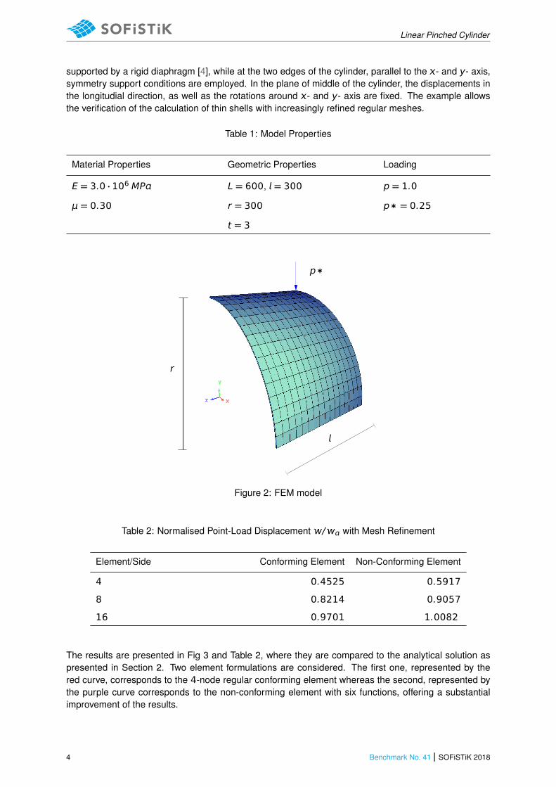
The properties of the model are defined in Table 1. The geometric parameters and the material are alldimensionless. The compressive point load p = 1.0 is applied radially and in opposite directions atthe middle nodes of the cylinder, as shown in Fig. 1. Using symmetry, only one-eighth of the cylinderneeds to be modeled, as shown in Fig. 2. For the simplified model only one fourth of the load p∗is applied at the the upper middle node, as it can be visualised in Fig. 2. The end of the cylinder is
SOFiSTiK 2018 | Benchmark No. 41 3
Linear Pinched Cylinder
supported by a rigid diaphragm [4], while at the two edges of the cylinder, parallel to the - and y- axis,symmetry support conditions are employed. In the plane of middle of the cylinder, the displacements inthe longitudial direction, as well as the rotations around - and y- axis are fixed. The example allowsthe verification of the calculation of thin shells with increasingly refined regular meshes.
Table 1: Model Properties
Material Properties Geometric Properties Loading
E = 3.0 · 106 MP L = 600, = 300 p = 1.0
μ = 0.30 r = 300 p∗ = 0.25
t = 3
p∗
r
Figure 2: FEM model
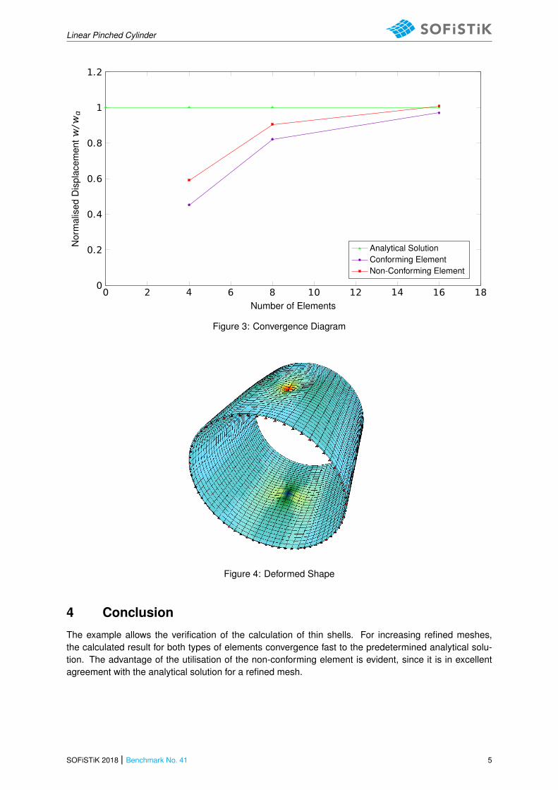
Table 2: Normalised Point-Load Displacement / with Mesh Refinement
Element/Side Conforming Element Non-Conforming Element
4 0.4525 0.5917
8 0.8214 0.9057
16 0.9701 1.0082
The results are presented in Fig 3 and Table 2, where they are compared to the analytical solution aspresented in Section 2. Two element formulations are considered. The first one, represented by thered curve, corresponds to the 4-node regular conforming element whereas the second, represented bythe purple curve corresponds to the non-conforming element with six functions, offering a substantialimprovement of the results.
4 Benchmark No. 41 | SOFiSTiK 2018
Linear Pinched Cylinder
0 2 4 6 8 10 12 14 16 180
0.2
0.4
0.6
0.8
1
1.2
Number of Elements
Nor
mal
ised
Dis
plac
emen
t/
Analytical SolutionConforming ElementNon-Conforming Element
Figure 3: Convergence Diagram
Figure 4: Deformed Shape
4 Conclusion
The example allows the verification of the calculation of thin shells. For increasing refined meshes,the calculated result for both types of elements convergence fast to the predetermined analytical solu-tion. The advantage of the utilisation of the non-conforming element is evident, since it is in excellentagreement with the analytical solution for a refined mesh.
SOFiSTiK 2018 | Benchmark No. 41 5

Linear Pinched Cylinder
5 Literature
[1] VDI 6201 Beispiel: Softwaregestutze Tragwerksberechnung - Beispiel Zylinderschale mit starrenEndscheiben, Kategorie 1: Mechanische Grundlagen. Verein Deutscher Ingenieure e. V.
[2] T. Belytschko et al. “Stress Projection for Membrane and Shear Locking in Shell Finite Elements”.In: Computer Methods in Applied Mechanics and Engineering 53(1-3) (1985), pp. 221–258.
[3] T. Rabczuk, P. M. A. Areias, and T. Belytschko. “A meshfree thin shell method for non-linear dynamicfracture”. In: International Journal for Numerical Methods in Engineering 72(5) (2007), pp. 524–548.
[4] P. Krysl and T. Belytschko. “Analysis of thin shells by the element-free Galerkin method”. In: Inter-national Journal for Solids and Structures 33(20-22) (1996), pp. 3057–3080.
6 Benchmark No. 41 | SOFiSTiK 2018