linear dc power supply - gwinstek.com output voltage is controlled by the output switch. ... switch...
TRANSCRIPT
Linear DC Power Supply
GPR-U Series
USER MANUAL GW INSTEK PART NO. 82PR-3520HME1
ISO-9001 CERTIFIED MANUFACTURER
This manual contains proprietary information, which is protected by copyright. All rights are reserved. No part of this manual may be photocopied, reproduced or translated to another language without prior written consent of Good Will Corporation.
The information in this manual was correct at the time of printing. However, Good Will continues to improve its products and therefore reserves the right to change the specifications, equipment, and maintenance procedures at any time without notice.
Good Will Instrument Co., Ltd. No. 7-1, Jhongsing Rd., Tucheng Dist., New Taipei City 236, Taiwan.

TABLE OF CONTENTS
3
Table of Contents SAFETY INSTRUCTIONS ............................................. 4
THEORY OF OPERATION ............................................ 7 Low Voltage Circuit ................................................ 7
High Voltage Circuit .............................................. 9
GETTING STARTED ................................................... 11 Product Introduction ........................................... 11
Front Panel Overview ........................................... 12
Rear Panel ........................................................... 16
OPERATION INSTRUCTIONS .................................... 19 Precaution ........................................................... 19
Setting Current Limit ........................................... 20
Constant Voltage / Constant Current Characteristics ..................................................... 21
APPENDIX ................................................................. 23 Specifications ...................................................... 23
GPR-U Series User Manual
4
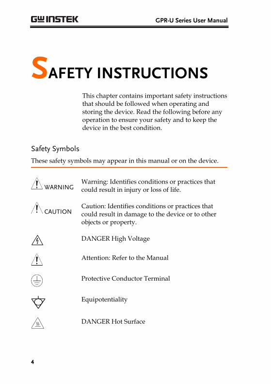
SAFETY INSTRUCTIONS This chapter contains important safety instructions that should be followed when operating and storing the device. Read the following before any operation to ensure your safety and to keep the device in the best condition.
Safety Symbols
These safety symbols may appear in this manual or on the device.
WARNING Warning: Identifies conditions or practices that could result in injury or loss of life.
CAUTION Caution: Identifies conditions or practices that could result in damage to the device or to other objects or property.
DANGER High Voltage
Attention: Refer to the Manual
Protective Conductor Terminal
Equipotentiality
DANGER Hot Surface

SAFETY INSTRUCTIONS
5
Do not dispose electronic equipment as unsorted municipal waste. Please use a separate collection facility or contact the supplier from which this instrument was purchased.
Safety Guidelines
General Guideline
CAUTION
Do not place heavy objects on the device.
Avoid severe impact or rough handling that may damage the device.
Avoid discharges of static electricity on or near the device.
Use only mating connectors, not bare wires, for the terminals.
Do not block the cooling fan vent.
The device should only be disassembled by a qualified technician.
Power Supply
WARNING
AC Input voltage: 120V ± 10%, 50/60Hz (AC 220V or 240V order made)
Connect the protective grounding conductor of the AC power cord to an earth ground.
Cleaning the power supply
Disconnect the power cord before cleaning the power supply.
Use a soft cloth dampened in a solution of mild detergent and water. Do not spray any liquid into the power supply.
Do not use chemicals containing harsh products such as benzene, toluene, xylene, and acetone.
Operation Environment
Location: Indoor, no direct sunlight, dust free, almost non-conductive pollution.
Relative Humidity: < 80%
Temperature: 0°C to 40°C

GPR-U Series User Manual
6
Storage environment
Location: Indoor
Relative Humidity: < 70%
Temperature: -10°C to 70°C
Disposal
Do not dispose this instrument as unsorted municipal waste. Please use a separate collection facility or contact the supplier from which this instrument was purchased. Please make sure discarded electrical waste is properly recycled to reduce environmental impact.

THEORY OF OPERATION
7
THEORY OF OPERATION
Low Voltage Circuit
Background The power supply can be divided into the following blocks: (1) AC input circuit, (2) transformer, (3) bias supply consisting of a rectifier and filter providing a reference voltage source, (4) main regulator circuit consisting of the main rectifier and associated filters, (5) series regulator, (6) current comparator, (7) voltage comparator, (8) reference voltage amplifier, (9) instant over load protection circuit and (10) relay control circuit.
The circuit elements consist of several integrated circuit (U201~U205, U101).
The circuit arrangement is shown as block diagram in Fig. 1.
Single Phase input power is applied to the transformer through the input circuit.
Auxiliary rectifier D101-D104 provides a bias voltage filtered by capacitor C101~ C104 for the pre-regulator U101, Q101 and Q102.
The main rectifier is a full wave bridge rectifier. The power is filtered by capacitor C401-C408 and then regulated via a series regulator.
U204 provides a reference voltage for U205
GPR-U Series User Manual
8
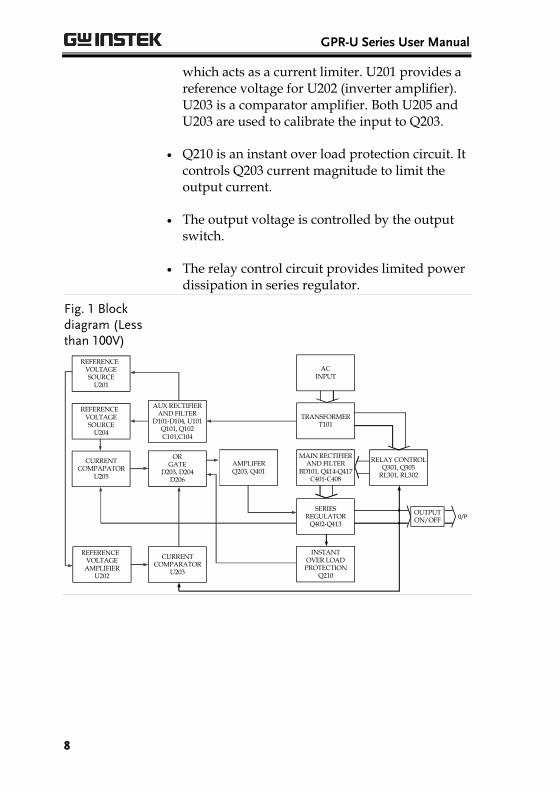
which acts as a current limiter. U201 provides a reference voltage for U202 (inverter amplifier). U203 is a comparator amplifier. Both U205 and U203 are used to calibrate the input to Q203.
Q210 is an instant over load protection circuit. It controls Q203 current magnitude to limit the output current.
The output voltage is controlled by the output switch.
The relay control circuit provides limited power dissipation in series regulator.
Fig. 1 Block diagram (Less than 100V)
RELAY CONTROLQ301, Q305
RL301, RL302
MAIN RECTIFIERAND FILTER
BD101, Q414-Q417C401-C408
AMPLIFERQ203, Q401
ORGATE
D203, D204D206
AUX RECTIFIERAND FILTER
D101-D104, U101Q101, Q102C101,C104
ACINPUT
INSTANTOVER LOAD
PROTECTIONQ210
TRANSFORMERT101
REFERENCEVOLTAGESOURCE
U204
REFERENCEVOLTAGESOURCE
U201
CURRENTCOMPAPATOR
U205
CURRENTCOMPARATOR
U203
REFERENCEVOLTAGE
AMPLIFIERU202
SERIESREGULATOR
Q402-Q4130/P
OUTPUTON/OFF
THEORY OF OPERATION
9
High Voltage Circuit
Background
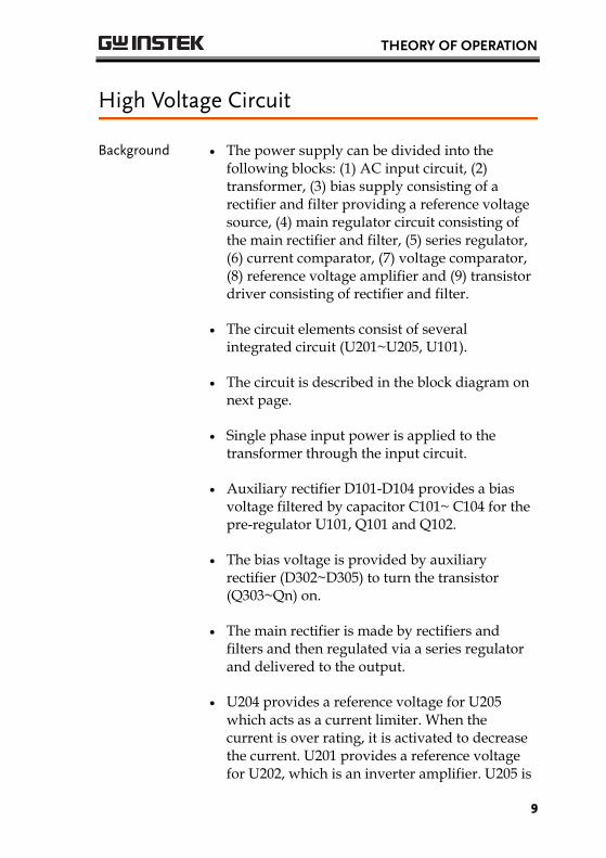
The power supply can be divided into the following blocks: (1) AC input circuit, (2) transformer, (3) bias supply consisting of a rectifier and filter providing a reference voltage source, (4) main regulator circuit consisting of the main rectifier and filter, (5) series regulator, (6) current comparator, (7) voltage comparator, (8) reference voltage amplifier and (9) transistor driver consisting of rectifier and filter.
The circuit elements consist of several integrated circuit (U201~U205, U101).
The circuit is described in the block diagram on next page.
Single phase input power is applied to the transformer through the input circuit.
Auxiliary rectifier D101-D104 provides a bias voltage filtered by capacitor C101~ C104 for the pre-regulator U101, Q101 and Q102.
The bias voltage is provided by auxiliary rectifier (D302~D305) to turn the transistor (Q303~Qn) on.
The main rectifier is made by rectifiers and filters and then regulated via a series regulator and delivered to the output.
U204 provides a reference voltage for U205 which acts as a current limiter. When the current is over rating, it is activated to decrease the current. U201 provides a reference voltage for U202, which is an inverter amplifier. U205 is

GPR-U Series User Manual
10
a comparator amplifier. It may be used to compare the reference voltage and the feedback voltage to calibrate the input voltage to Q202 and Q203.
The output voltage is controlled by the output switch
Fig. 2 Block diagram (more than 100V)
RELAY CONTROLQ301, Q305
RL301, RL302
MAIN RECTIFIERAND FILTER
BD101, Q414-Q417C401-C408
AMPLIFERQ203, Q401
ORGATE
D203, D204D206
AUX RECTIFIERAND FILTER
D101-D104, U101Q101, Q102C101,C104
ACINPUT
INSTANTOVER LOAD
PROTECTIONQ210
TRANSFORMERT101
REFERENCEVOLTAGESOURCE
U204
REFERENCEVOLTAGESOURCE
U201
CURRENTCOMPAPATOR
U205
CURRENTCOMPARATOR
U203
REFERENCEVOLTAGE
AMPLIFIERU202
SERIESREGULATOR
Q402-Q4130/P
OUTPUTON/OFF

GETTING STARTED
11
GETTING STARTED
Product Introduction
Description The regulated DC power supplies GPR-U series and GPR-Super series have been designed to cover the most often required applications in laboratories, schools and production lines.
The output voltage can be adjusted from 0 to the rated voltage in one single range by coarse and fine potentiometer. The load current can be varied from 0 to the rated current by coarse and fine potentiometer. Both outputs can be accurately read on the integrated voltmeter and ammeter.
Both stability and ripple are at high standard and meet the requirements of modern circuit design. The unit can be used as either constant voltage or constant current source. The various mode of operation are described in greater details in the Operation Instructions Section.

GPR-U Series User Manual
12
Front Panel Overview
GPR-U Series
No. Name Description
1 CV Indicator Lights when the power is on and in constant voltage operation.
2 CC Indicator Lights when the device is in constant current operation.
3 Voltage Coarse and fine voltage control knob.
4 Current Coarse and fine current control knob.
5 “+” output terminal Positive polarity, load current (Red).
6 “GND” terminal Earth and chassis ground (Green).
7 “–"output terminal Negative polarity (Black).
8 Voltmeter Indicates the output voltage.
9 Ammeter Indicates the output current.
10 Power control Unit On/Off switch with overvoltage and overcurrent tripped crowbar.

GETTING STARTED
13
11 Current limit switch When the current limit switch is pushed, the Ammeter indicates the value of the current limit setting.
12 O.V.P. switch When the O.V.P. switch is pushed, the Voltmeter indicates the value of the over voltage protection setting.
13 O.V.P. adjust For the O.V.P. adjustment of the over voltage protection setting value.
14 Output switch Turns on / off the output.
15 Output indicator Lights when the output switch is turned on.
16
Caution high voltage
Caution, potential of 100V or more may be present on the terminals.
GPR-U Series User Manual
14
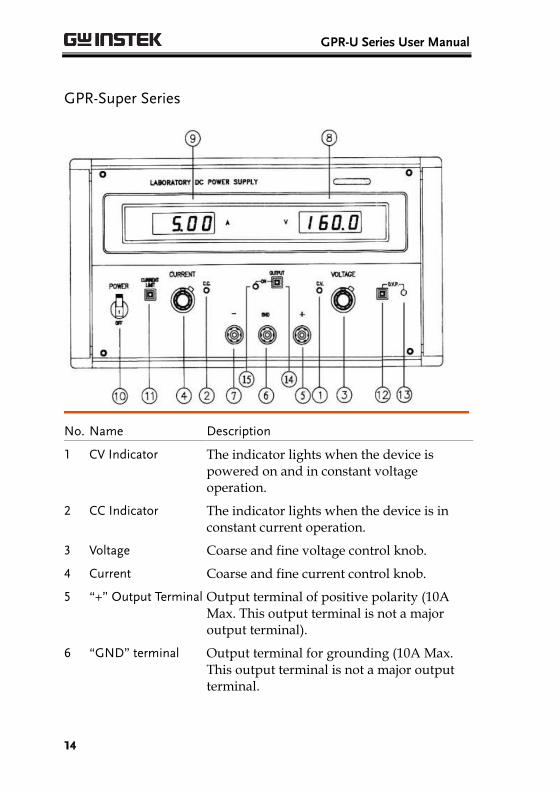
GPR-Super Series
No. Name Description
1 CV Indicator The indicator lights when the device is powered on and in constant voltage operation.
2 CC Indicator The indicator lights when the device is in constant current operation.
3 Voltage Coarse and fine voltage control knob.
4 Current Coarse and fine current control knob.
5 “+” Output Terminal Output terminal of positive polarity (10A Max. This output terminal is not a major output terminal).
6 “GND” terminal Output terminal for grounding (10A Max. This output terminal is not a major output terminal.
GETTING STARTED
15
7 “–" Output Terminal Output terminal of negative polarity (10A Max. This output terminal is not a major output terminal).
8 Voltmeter Indicates the output voltage (Digital power meter).
9 Ammeter Indicates the output current (Digital power meter).
10 Power control Unit On/Off switch with overvoltage and overcurrent tripped crowbar.
11 Current limit switch When the current limit switch is pushed, the Ammeter indicates the value of the current limit setting.
12 O.V.P. switch When the O.V.P. switch is pushed, the Voltmeter indicates the value of the over voltage protection setting.
13 O.V.P. adjust For the O.V.P. adjustment of the over voltage protection setting value.
14 Output switch Turns on/off the output.
15 Output indicator The indicator lights when the output voltage switch is turned on.
WARNING Warning: Do not touch the output terminal after power is on to avoid electrical shock.

GPR-U Series User Manual
16
Rear Panel
GPR-U Series
No. Name Description
17 “L” terminal AC. Live input terminal.
18 “N” terminal AC. Neutral input terminal
19 GND terminal Earth and chassis ground.
20 Cooling fan Ventilates the hot air out.
21 “S-” terminal Negative polarity sense terminal.
22 “-” terminal Negative polarity output terminal.
23 “+” terminal Positive polarity output terminal.
24 “S+” terminal Positive polarity sense terminal.
25 GND terminal Earth and chassis ground.
NOTE If the load current is greater than 10A, then the rear panel terminals (21 to 25) must be used.
WARNING Warning: Do not touch the output terminal after power is on to avoid electrical shock.

GETTING STARTED
17
GPR-Super Series
No. Name Description
17 “L” terminal AC. Live input terminal.
18 “N” terminal AC. Neutral input terminal
19 GND terminal Earth and chassis ground.
20 Cooling fan Ventilates the hot air out.
21 “S-” terminal Negative polarity sense terminal.
22 “-” terminal Negative polarity output terminal.
23 “+” terminal Positive polarity output terminal.
24 “S+” terminal Positive polarity sense terminal.
25 GND terminal Earth and chassis ground.
26 Control input “+” terminal
The positive polarity +10V input terminal of external control
27 Control input “-” terminal
The negative polarity -10V input terminal of external control
28 Master When the switch is in this position, the voltage and current settings are controlled by the front panel control knobs.
GPR-U Series User Manual
18
29 Control When the switch is in this position, the voltage and current settings can be controlled remotely via the control input 10V terminals.
NOTE If the load current is greater than 10A, then the rear panel terminals (21 to 25) must be used.
WARNING Warning: Do not touch the output terminal after power is on to avoid electrical shock.

OPERATION INSTRUCTIONS
19
OPERATION
INSTRUCTIONS
Precaution
AC input AC input should be within the range of line voltage±10% at 50/60Hz.
Installation Avoid using the power supply in a place where ambient temperature exceeds 40℃. The heat sink
locate at the rear of the power supply must have sufficient air space for radiation.
Output voltage overshoot
Voltage between output terminals never exceeds the preset value when the power is turned on or off.

GPR-U Series User Manual
20
Setting Current Limit
Procedure 1. Determine the maximum safe current for the device to be powered.
2. Push the current limit switch.
3. Rotate the Coarse Voltage Control Knob away from zero sufficiently for the CC indicator to light.
4. Adjust the current limit to the desired value by rotating the Current Control Knob. You can read the current value on the Ammeter.
5. The current limit (overload protection) has now been preset. Do not change the Current Limit setting after this step.
6. Release the current limit switch.

OPERATION INSTRUCTIONS
21
Constant Voltage / Constant Current Characteristics
Background The regulated DC power supplies GPR-U series and GPR-Super series are Constant Voltage / Constant Current automatic crossover type of power supplies. This allows continuous operation during transition from constant current to constant voltage modes in response to the load change. The intersection point of constant voltage and constant current modes is called the crossover point. Fig.3 shows the relationship between this crossover point and the load.
For example, if the load is such that the power supply is operating in constant voltage mode, a regulated output voltage is provided. The output voltage remains constant as the load increases, up until the point where the preset current limit is reached. At that point, the output current becomes constant and the output voltage will start to drop in proportion to further increase in load. The crossover point is indicated by the front panel LED indicators. The crossover point in that case is reached when the CV indicator turns off and the CC indicator turns on.

GPR-U Series User Manual
22
Similarly, crossover from constant current to constant voltage mode automatically occurs from a decrease in load. A good example of this would be seen when charging a 12 volt battery. Initially, the open circuit voltage of the power supply may be preset for 13.8 volts. A low battery will place a heavy load on the power supply and it will operate in constant current mode, which may be adjusted for a 1 amp charging rate. As the battery becomes charged, and its voltage approaches 13.8 volts, its load decreases to the point where it no longer demands the full 1 amp charging rate. This is the crossover point where the power supply goes into constant voltage mode.
Fig. 3 Constant Voltage/Constant Current Characteristic
ConstantVoltageRange
Crossover Point
V0 MAXI0 MAX
Constant CurrentRange
OutputVoltage
Output Current

APPENDIX
23
APPENDIX
Specifications All specifications are applicable only when the rear panel terminals are used. If the front panel terminals are used or if operating with long cables, remote sense must be connected to the terminals.
The specifications apply when the device is powered on for at least 30 minutes under +20°C~+30°C.
General Main supply
AC120±10% 50/60Hz(Otherwise by order made)
Rating, dimension and weight
See Table 1 and table2
Operation mode Series Operation
Operation Environment
Indoor use
Operation Temperature &Humidity
0˚C to 40˚C, <80%.
Storage Temperature & Humidity
-10˚C to 70˚C, < 70%.
Accessories
Operation Manual
Test Lead: GTL-10(Current<4A)*1, or GTL-104(Current≦10A)*1
Note: No Test Lead included to the unit with its current greater than 10A or voltage greater than 600V.
Constant Voltage Operation
Output Voltage ranges 0 to rating voltage adjustable continuously
Voltage regulation
line regulation≦0.01%+3mV.
load regulation≦0.01%+5mV.
load regulation≦0.02%+5mV(≧10A).
Recovery time ≦100μs (50% Load change, minimum
load 0.5A)

GPR-U Series User Manual
24
Ripple & Noise ≦2mVrms (5Hz~1MHz).
Temperature coefficient
≦300ppm/˚C
OVP setting ranges from 15% to 105% of rate voltage continuously adjustable
Constant Current Operation
Output current range 0 to rating current adjustable continuously
Current regulation line regulation≦0.2%+3mA
load regulation≦0.2%+5mA
Ripple
≦5mArms(≦20A)
≦20mArms(≦50A)
≦100mArms(≦100A)
Indicator Meter
Display 3 1/2 Digits 0.5” Red LED display.
Accuracy ±(0.5% of rdg + 2 digits)
Voltage range
19.99V of full scale(rating voltage≦18V)
199.9V of full scale(rating voltage≦180V)
1999V of full scale(rating voltage≦1800V)
Current range
1.999A of full scale(rating current≦1.8A)
19.99A of full scale(rating current≧18A)
199.9A of full scale(rating current≦180A)
Insulation
Between chassis and output terminal
100MΩ or above(DC1000V)
Between Chassis and AC cord
100MΩ or above (DC1000V).
Table 1 GPR-U Model
Max. Rating Dimensions Weight
Volts(V) Amps(A) WxHxD(m/m) Kg
GPR-100H05D 1000 0.5
430(W) 178(H) 572(D)
28.5
GPR-60H15D 600 1.5 30.5
GPR-50H15D 500 1.5 29.5
GPR-35H20D 350 2 29.5
GPR-25H30D 250 3 29.5
GPR-16H50D 160 5 30.5
GPR-7510HD 75 10 29.5
GPR-6015HD 60 15 30.0
GPR-3520HD 35 20 29.5
GPR-1850HD 18 50 30.0

APPENDIX
25
Note 1. Special order 8 volts to 1000 volts and 0.5 Amps to 75
Amps under 1kVA available. Rear-Panel Output for GPR-1850HD/3520HD/6015HD.
2. In addition to the specifications listed above, GW Instek can also manufacture GPR series power supplies with customized specifications.
Warning When the voltage exceeds 60VDC, users might be in danger of electric shock. When connecting the power supplies in series, please be careful as the voltage between connection terminals and ground terminals may reach 60VDC or higher.
Table 2
GPR-Super Model
Max. Rating Dimensions Remote function
Weight
Volts(V) Amps(A) WxHxD(m/m) External 10V
Remote control Kg
GPR-100H05DA 1000 0.5
300(W) 194(H) 558(D)
Without 26.5
GPR-60H15DA 600 1.5 Without 26.5
GPR-50H15DA 500 1.5 Without 26.5
GPR-35H20DA 350 2 Without 26.5
GPR-25H30DA 250 3 Without 26.5
GPR-16H50DA 160 5 Without 26.5
GPR-7510HDA 75 10 Without 26.5
GPR-6015HDA 60 15 Without 26.5
GPR-3520HDA 35 20 Without 26.5
GPR-7510HDC 75 10 With 26.5
GPR-6015HDC 60 15 With 26.5
GPR-3520HDC 35 20 With 26.5
Note In addition to the specifications listed above, GW Instek can also manufacture GPR series power supplies with customized specifications.

GPR-U Series User Manual
26
Warning When the voltage exceeds 60VDC, users might be in danger of electric shock. When connecting the power supplies in series, please be careful as the voltage between connection terminals and ground terminals may reach 60VDC or higher.