line product specifications multi-beam...
TRANSCRIPT

MULTI-BEAM ® SensorsCompact modular self-contained photoelectric sensing controls
Printed in USA P/N 32887
Product
Line Specifications
•
•
•
•
•
Modular design with interchangeable components (scannerblocks, power blocks, and logic timing modules);over 5,000 sensor configurations possible
Scanner blocks for opposed, retro, diffuse, convergent, andfiber optic sensing modes (including high-gain models)
Power blocks for ac or dc operation, including 2-wire acoperation
Logic modules to support a wide variety of delay, pulse, limit,and rate sensing logic functions
Most scanner blocks include Banner's exclusive, patentedAID™ (Alignment Indicating Device) system, which lights atop-mounted indicator LED whenever the sensor sees itsown modulated light source, and pulses the LED at a rateproportional to the strength of the received light signal.
3.7"(94 mm)
1.6"(40 mm)
4.5"(114 mm)
2.1" (53 mm)
Status Indicator LED(except emitters)
Lens Centerline
Access toSensitivity Adjustment
2.36"(60.0 mm)
0.30"(7.6 mm)
0.20"(5.1 mm)
5 mm (#10) ScrewClearance (4)
1.18"(30.0 mm)
1/2" – 14 NPSMConduit Entrance

Banner Engineering Corp. 9714 Tenth Ave. No. Minneapolis, MN 55441 Telephone: (612)544-3164 FAX (applications): (612)544-3573
WARNING MULTI-BEAM ® photoelectric presence sensors described in this catalog do NOT include the self-checking redundant circuitry necessary to allow their use in personnel safety applications. A sensor failure or malfunctioncan result in either an energized or a de-energized sensor output condition.
Never use these products as sensing devices for personnel protection. Their use as a safety device may create an unsafecondition which could lead to serious injury or death.
Only MACHINE-GUARD and PERIMETER-GUARD Systems, and other systems so designated, are designed to meet OSHA and ANSImachine safety standards for point-of-operation guarding devices. No other Banner sensors or controls are designed to meet these standards,and they must NOT be used as sensing devices for personnel protection.
!
WARRANTY: Banner Engineering Corporation warrants its products to be free from defects for one year. Banner Engineering Corporation willrepair or replace, free of charge, any product of its manufacture found to be defective at the time it is returned to the factory during the warranty period.This warranty does not cover damage or liability for the improper application of Banner products. This warranty is in lieu of any other warranty eitherexpressed or implied.
Contents
Introduction to MULTI-BEAM® Modular Sensors ........................... page 3Selection of components and summary of available models ............ pages 4-6MULTI-BEAM ® 3- and 4-wire Sensors............................................ pages 6-23
3- and 4-wire Scanner Blocks ................................................. pages 6-143- and 4-wire Scanner Block modifications ........................... page 143- and 4-wire Power Blocks ................................................... pages 15-203- and 4-wire Logic Modules ................................................. pages 21-23
MULTI-BEAM ® 2-wire Sensors ....................................................... pages 24-292-wire Scanner Blocks ............................................................ pages 24-262-wire Power Blocks .............................................................. pages 27-282-wire Logic Modules ............................................................ page 29
MULTI-BEAM ® Accessories............................................................ pages 30-31Upper Covers (lens assemblies).............................................. page 30Lower Covers ......................................................................... page 30Mounting Brackets ................................................................. page 31Quick Disconnect ................................................................... page 31

Banner MULTI-BEAM® sensors are compact modular self con-tained photoelectric switches. Each MULTI-BEAM consists ofthree components: scanner block, power block, and logic module.The scanner block contains the complete modulated photoelectricamplifier as well as the emitter and receiver optoelements. It alsocontains the sensing optics and the housing for the other twomodules. The power block provides the interface between thescanner block and the external circuit. It contains a power supplyfor the MULTI-BEAM plus a switching device to interface thecircuit to be controlled. The logic module interconnects the powerblock and scanner block both electrically and mechanically. Itprovides the desired timing logic function (if any), plus the abilityto program the output for either light- or dark-operate. Theemitters of MULTI-BEAM emitter-receiver pairs do not requirea logic module. Emitter scanner blocks are supplied with a blade-pin to interconnect the scanner block and power block. Thismodular design, with field-replaceable power block and logicmodule, permits over 5,000 sensor configurations, resulting inexactly the right sensor for any photoelectric application.
There are two families of MULTI-BEAM sensors: 3- and 4-wire,and 2-wire. Three- and four-wire MULTI-BEAMs offer thegreatest selection of sensor configurations. They permit either acor dc operation and offer the fastest response times and thegreatest sensing ranges. Two-wire MULTI-BEAMs are used inac-powered applications where simplicity and convenience ofwiring are important. They are physically and electrically inter-changeable with heavy-duty limit switches.
The circuitry of all MULTI-BEAM components is encapsulatedwithin rugged, corrosion-resistant VALOX® housings, whichmeet or exceed NEMA 1, 3, 12, and 13 ratings. Most MULTI-BEAM scanner blocks include Banner's patented AlignmentIndicating Device (AID™) which lights a top-mounted LEDwhen the sensor sees its own modulated light source and pulsesthe LED at a rate proportional to the received light signal. MostMULTI-BEAM sensor assemblies are UL listed and certified byCSA (see power block listings). All MULTI-BEAM components(except power block models 2PBR and 2PBR2) are totally solid-state for unlimited life.
Composite Functional Schematic, 3- and 4-wire Sensors
®
3
MULTI-BEAM Sensors
LR41887E71083

MULTI-BEAM sensors are made up of three components: scannerblock, power block, and logic module. This is true for all MULTI-BEAMs with the exception of opposed mode emitter units whichrequire only a power block (no logic module).
The first decision in the component selection process is to determinewhich family of MULTI-BEAM sensors is appropriate for the applica-tion: 3- and 4-wire, or 2-wire.
Next, decide which scanner block (within the selected family) is best forthe application. The guidelines in the catalog introduction will help youto determine the best sensing mode. Then narrow the choice bycomparing the specifications listed in the following charts and on thepages referenced in the charts.
Finally, choose a power block and logic module to complete theMULTI-BEAM assembly. Components snap together without inter-wiring to form a complete photoelectric sensing system that meets yourexact requirements while maintaining the simplicity of a self-containedsensor.
If you have any questions about selecting MULTI-BEAM components,please contact your Banner sales engineer or call Banner's ApplicationsDepartment at (612) 544-3164 during normal business hours.
Scanner Blocks Model Sensing Mode Range Response Page
SBE & SBR1 Opposed: high speed 150 feet 1 millisecond p. 7SBED & SBRD1 Opposed: high speed, narrow beam 10 feet 1 millisecond p. 7SBEX & SBRX1 Opposed: high power, long range 700 feet 10 milliseconds p. 7SBEV & SBRX1 Opposed: visible beam 100 feet 10 milliseconds p. 7SBEXD & SBRXD1 Opposed: high power, wide beam angle 30 feet 10 milliseconds p. 7
SBLV1 Retroreflective: high speed, visible beam 30 feet 1 millisecond p. 8SBLVAG1 Retroreflective: polarized beam (anti-glare) 15 feet 1 millisecond p. 8SBL1 Retroreflective: high speed, infrared beam 30 feet 1 millisecond p. 8SBLX1 Retroreflective: high power, long range 100 feet 10 milliseconds p. 8
SBD1 Diffuse (proximity): high speed 12 inches 1 millisecond p. 9SBDL1 Diffuse (proximity): medium range 24 inches 1 millisecond p. 9SBDX1 Diffuse (proximity): high power, long range 6 feet 10 milliseconds p. 9SBDX1MD Diffuse (proximity): wide beam angle 24 inches 10 milliseconds p. 9
SBCV1 Convergent beam: high speed, visible red 1.5-inch focus 1 millisecond p. 10SBCVG1 Convergent beam: high speed, visible green 1.5-inch focus 1 millisecond p. 10
SBC1 Convergent beam: high speed, infrared 1.5-inch focus 1 millisecond p. 10SBC1-4 Convergent beam: high speed, infrared 4-inch focus 1 millisecond p. 10SBC1-6 Convergent beam: high speed, infrared 6-inch focus 1 millisecond p. 10
SBCX1 Convergent beam: high power, infrared 1.5-inch focus 10 milliseconds p. 10SBCX1-4 Convergent beam: high power, infrared 4-inch focus 10 milliseconds p. 10SBCX1-6 Convergent beam: high power, infrared 6-inch focus 10 milliseconds p. 10
SBEF & SBRF1 Opposed fiber optic (glass fibers): high speed see specs 1 millisecond p. 11SBEXF & SBRXF1 Opposed fiber optic (glass fibers): high power see specs 10 milliseconds p. 11
SBFX1 Fiber optic (glass fibers): high power, infrared see specs 10 milliseconds p. 11SBF1 Fiber optic (glass fibers): high speed, infrared see specs 1 millisecond p. 12SBF1MHS Fiber optic (glass fibers): very high speed see specs 0.3 millisecond p. 12SBFV1 Fiber optic (glass fibers): visible red see specs 1 millisecond p. 13SBFVG1 Fiber optic (glass fibers): visible green see specs 1 millisecond p. 13
SBAR1 Ambient light receiver see specs 10 milliseconds p. 14SBAR1GH Ambient light receiver: high gain see specs 10 milliseconds p. 14SBAR1GHF Ambient light receiver: for glass fiber optics see specs 10 milliseconds p. 14
3- and 4-wire Systems (pages 6 through 23)
Upper Cover (lens)(supplied withScanner Block)
Lower Cover(supplied withScanner Block) Logic
TimingAdjustment
LIGHT/DARKOperate Select
PowerBlock
WiringTerminals
Scanner BlockHousingLogic Module
4
Selection of MULTI-BEAM Components

Logic Modules Model Timing Logic Function Time Range(s) Page
LM1 ON/OFF (no timing function), light operate only NOTE for items below: other p. 21LM3 ON/OFF (no timing function), light or dark operate time ranges available (p. 23) p. 21
LM5 ON-delay .15 to 15 seconds p. 22LM5R OFF-delay .15 to 15 seconds p. 22LM5-14 ON & OFF delay .15 to 15 seconds (both delays) p. 22LM5T Limit timer (time-limited ON/OFF) .15 to 15 seconds p. 22
LM4-2 One-shot, retriggerable .01 to 1 second p. 21LM4-2NR One-shot, non-retriggerable .01 to 1 second p. 22LM8-1 Delayed one-shot .15 to 15 seconds (both times) p. 23LM8A ON-delay one-shot .15 to 15 seconds (both times) p. 23
LM6-1 Rate sensor 60 to 1200 pulses per minute p. 22LM8 Repeat cycle timer .15 to 15 seconds (both times) p. 23
LM2 Alternate action, divide by 2 p. 21LM10 Alternate action, divide by 10 p. 23
LMT Test module p. 23
3- and 4-wire Systems (pages 6 through 23)
2-wire Systems (pages 24 through 29)
AgencyPower Blocks Model Input Voltage Output Configuration Approvals Page
PBT 10 to 30V dc SPST NPN (sink), 250mA maximum UL & CSA p. 15PBT2 10 to 30V dc SPDT NPN (sink), 250mA each output p. 15PBP 10 to 30V dc SPST PNP (source), 250mA maximum UL & CSA p. 15PBT-1 10 to 30V dc No output: for powering emitters UL & CSA p. 16
PBT48 44 to 52V dc SPST NPN (sink), 250mA maximum p. 15PBP48 44 to 52V dc SPST PNP (source), 250mA maximum p. 15PBT48-1 44 to 52V dc No output: for powering emitters p. 16
PBD-2 11 to 13V ac (50/60Hz) SPST SCR, 3/4 amp maximum p. 17PBD 22 to 28V ac (50/60Hz) SPST SCR, 3/4 amp maximum UL & CSA p. 17PBD-1 22 to 28V ac (50/60Hz) No output: for powering emitters p. 19
PBA 105 to 130V ac (50/60Hz) SPST SCR, 3/4 amp maximum UL & CSA p. 17PBAQ 105 to 130V ac (50/60Hz) SPST SCR, normally closed, 3/4 amp max. UL & CSA p. 19PBAT 105 to 130V ac (50/60Hz) SPST isolated transistor, 100mA max. (ac or dc) UL & CSA p. 18PBO 105 to 130V ac (50/60Hz) SPST isolated transistor, 50mA max. (dc only) UL & CSA p. 18PBAM 105 to 130V ac (50/60Hz) Voltage source: 8V dc at 8ma max. UL & CSA p. 18PBA-1 105 to 130V ac (50/60Hz) No output: for powering emitters UL & CSA p. 19
PBB 210 to 250V ac (50/60Hz) SPST SCR, 3/4 amp maximum UL & CSA p. 17PBBT 210 to 250V ac (50/60Hz) SPST isolated transistor, 100mA max. (ac or dc) UL & CSA p. 18PBOB 210 to 250V ac (50/60Hz) SPST isolated transistor, 50mA max. (dc only) UL & CSA p. 18PBB-1 210 to 250V ac (50/60Hz) No output: for powering emitters UL & CSA p. 19
Scanner Blocks Model Sensing Mode Range Response Page
SBE & 2SBR Opposed 150 feet 10 milliseconds p. 25
2SBL1 Retroreflective 30 feet 10 milliseconds p. 25
2SBD1 Diffuse (proximity): short range 12 inches 10 milliseconds p. 26
2SBDX1 Diffuse (proximity): long range 30 inches 10 milliseconds p. 26
2SBC1 Convergent beam 1.5-inch focus 10 milliseconds p. 25
2SBC1-4 Convergent beam 4-inch focus 10 milliseconds p. 25
2SBF1 Fiberoptic see specs 10 milliseconds p. 26
5

Power Blocks Model Input Voltage Output Configuration Agency Approvals Page2PBD 22 to 28V ac (50/60Hz) 2-wire, SPST SCR, 3/4 amp max. UL & CSA p. 272PBA 105 to 130V ac (50/60 Hz) 2-wire, SPST SCR, 3/4 amp max. UL & CSA p. 272PBB 210 to 250V ac (50/60Hz) 2-wire, SPST SCR, 3/4 amp max. UL & CSA p. 272PBR 105 to 130V ac (50/60Hz) 4-wire, SPST E/M relay, 5 amps max. p. 272PBR2 105 to 130V ac (50/60Hz) 4-wire, SPDT E/M relay, 5 amps max. p. 27
2-wire Systems (pages 24 through 29)
Logic Modules Model Timing Logic Function Time Range(s) Page2LM3 ON/OFF (no timing) p. 292LM5 ON-delay .15 to 15 seconds p. 292LM5R OFF-delay .15 to 15 seconds p. 292LM5-14 ON & OFF delay .15 to 15 seconds (both delays) p. 292LM5T Limit timer (time limited ON/OFF) .15 to 15 seconds (both delays p. 292LM4-2 One-shot, retriggerable .01 to 1 second p. 29LMT Test module p. 23
Other MULTI-BEAM Systems (described in Banner product catalog or in the data sheets noted below)
MULTI-BEAM 3- & 4-WIRESCANNER BLOCKS
Edgeguide Systems (data sheet 03506) Optical Data Transmitter (data sheet 03321) Light Screen System (data sheet 03557)
6
DESCRIPTIONMULTI-BEAM 3- & 4-wire scanner blocks offer a complete comple-ment of sensing modes. There are 3 or more models for each sensingmode, resulting in a choice of exactly the right sensor for any applica-tion. The high power models (10 millisecond response time) offergreater optical sensing power than any other industrial sensors.
SPECIFICATIONSSUPPLY VOLTAGE: input power and output connections are madevia a 3- or 4-wire power block (see pages 15 to 20).
RESPONSE TIME: 1 millisecond ON and OFF, except high gainmodels with "X" suffix and ambient light receivers which are 10milliseconds ON and OFF.
REPEATABILITY OF RESPONSE: see individual sensor specs.
SENSITIVITY ADJUSTMENT: easily accessible, located on top ofscanner block beneath o-ring gasketed screw cover. 15-turn clutchedcontrol (rotate clockwise to increase gain).
ALIGNMENT INDICATOR: red LED on top of scanner block.Banner's exclusive, patented Alignment Indicating Device (AID™)circuit lights the LED whenever the sensor detects its own modulatedlight source, and pulses the LED at a rate proportional to the receivedlight level.
CONSTRUCTION: reinforced VALOX® housing with componentstotally encapsulated. Stainless steel hardware. Meets NEMA standards1, 3, 12, and 13.
OPERATING TEMPERATURE RANGE: -40 to +70 degrees C(-40 to +158 degrees F).
VALOX ® is a registered trademark of General Electric Company.
Functional Schematic, 3- and 4-wire Scanner Block
Dimensions, 3- and 4-wire Scanner Block

SBEX & SBRX1
Range: 700 feet (200m)Response: 10ms on/offRepeatability: 0.7msBeam: infrared, 940nmEffective beam: 1" dia.
SBEV & SBRX1
Range: 100 feet (30m)Response: 10ms on/offRepeatability: 0.1msBeam: visible red, 650nmEffective beam: 1" dia.
SBEXD &SBRXD1
Range: 30 feet (9m)Response: 10ms on/offRepeatability: 0.7msBeam: infrared, 880nmEffective beam: .14" dia.
SBED & SBRD1
Range: 10 feet (3m)Response: 1ms on/offRepeatability: 0.03msBeam: infrared, 880nmEffective beam: .14" dia.
SBE & SBR1
Range: 150 feet (45m)Response: 1ms on/offRepeatability: 0.03msBeam: infrared, 940nmEffective beam: 1" dia.
SBE/SBR1: this opposed pair has the highest gain available at 1 ms response.SBED/SBRD1: fast response and small effective beam; will detect objects as small as .14 inch in crossectionmoving at up to 10 feet per second. Best choice for repeatability of position sensing.SBEX/SBRX1: best choice for opposed sensing in extremely dirty environments. Use for outdoor applicationsand all applications requiring opposed range of 100 feet or more. Also useable side-by-side for long-distancemechanical convergent sensing. Alignment difficult beyond 400 feet.SBEV/SBRX1: SBEV has visible red beam for easiest alignment and system monitoring.SBEXD/SBRXD1: wide beam angle and high gain for the most forgiving emitter-receiver alignment.
10
1
DISTANCE
100
1000
.1 FT 1 FT 10 FT 100 FT
SBED &SBRD1E
XCESS
GAINI
10
1
DISTANCE
100
1000
1 FT
SBEX &SBRX1
10 FT 100 FT 1000 FT
EXCESS
GAINI
10
1
DISTANCE
100
1000
.1 FT 1 FT 10 FT 100 FT
SBEXD &SBRXD1
EXCESS
GAINI
10
1
DISTANCE
100
1000
1 FT
SBEV &SBRX1
10 FT 100 FT 1000FT
EXCESS
GAINI
20
0
INCHES
OPPOSED DISTANCE--FEET
4 6 8 10
4
8
12
4
8
12
SBED/SBRD1
10
1
DISTANCE
100
1000
1 FT
SBE &SBR1
10 FT 100 FT 1000FT
EXCESS
GAINI
0
0
20
40
60
20
40
60
150 450 600 750
INCHES
SBEX/SBRX1
OPPOSED DISTANCE--FEET300
250
0
INCHES
OPPOSED DISTANCE--FEET
50 75 100 150
5
10
15
5
10
15
SBEV/SBRX1
0
0
10
20
30
10
20
30
6 12 18 24 32
INCHES
SBEXD/SBRXD1
OPPOSED DISTANCE--FEET
Models Excess GainSensing Mode
MULTI-BEAM 3- & 4-wire Scanner Blocks
300
0
INCHES
OPPOSED DISTANCE--FEET
60 90 120 150
20
40
60
20
40
60
SBE/SBR1
OBJECT
OPPOSED Mode
7
Beam Pattern

RETROREFLECTIVEMode
SBLV1: visible beam makes alignment very easy, and is the first choice for most retroreflective applications.Not for use in dirty environments; rather use opposed mode or see SBL1 & SBLX1, below. Do not locateretroreflector closer than 6 inches (15cm) from sensor.
SBLVAG1: uses anti-glare filter for immunity to direct reflections from shiny objects. Use only with modelsBRT-3 or BRT-1.5 retroreflective targets. Use only in clean environments. Do not locate retroreflector closerthan 12 inches (30cm) from sensor.
SBL1: use where invisible beam is advantageous (e.g. security applications or film processing). First choice forretroreflective sensing in slightly or moderately dirty environments. Do not use when the object to break thebeam has a shiny surface, unless the angle of light to the surface can be predicted.
SBLX1: highest gain available in a retroreflective sensor. Use for all applications requiring more than 30-footrange where opposed mode sensors cannot be used. Objects must pass at a distance of at least 10 feet from thesensor to be reliably sensed.
NOTE: for detailed information onavailable retroreflective materials, seethe Banner product catalog.
SBLV1
Range: 6 in. to 30 ft. (0,15 to 9m)Response: 1ms on/offRepeatability: 0.3msBeam: visible red, 650nm
SBLVAG1
Range: 12 in. to 15 ft. (0,3 to 4.5m)Response: 1ms on/offRepeatability: 0.3msBeam: visible red, 650nm
SBL1Range: 1 in. to 30 ft.(2,5cm to 9m)Response: 1ms on/offRepeatability: 0.3msBeam: infrared, 940nm
SBLX1
Range: 10 to 75 ft. (3 to22m) with one BRT-3 target;10 to 100 ft. (3 to 30m) withthree BRT-3 targetsResponse: 10ms on/offRepeatability: 1.5msBeam: infrared, 880nm
MULTI-BEAM 3- & 4-wire Scanner Blocks
10
1
DISTANCE
100
1000
.1 FT 1 FT 10 FT 100 FT
with BRT-3 3"reflector
with BRT-1 1"reflector
withBRT-Ttape
SBLV1EXCESS
GAINI
10
1
DISTANCE
100
1000
.1 FT 1 FT 10 FT 100 FT
EXCESS
GAINI
SBLVAG1
10
1
DISTANCE
100
1000
.1 FT 1 FT 10 FT 100 FT
with BRT-3 3"reflectorwith BRT-1 1"
reflector
withBRT-Ttape
SBL1EXCESS
GAINI
10
1
DISTANCE
100
1000
1 FT
with one BRT-3 3"reflector
SBLX1
with three BRT-3 3"reflectors
10 FT 100 FT 1000 FT
EXCESS
GAINI
0
0
2
4
6
2
4
6
6 12 18 24 32
INCHES
SBLV1
DISTANCE TO REFLECTOR--FEET
with BRT-3 reflector
0
0
1
2
3
1
2
3
3 6 9 12 15
INCHES
SBLVAG1
DISTANCE TO REFLECTOR--FEET
with BRT-3 reflector
0
0
2
4
6
2
4
6
6 12 18 24 32
INCHES
SBL1
DISTANCE TO REFLECTOR--FEET
with BRT-3 reflector
0
0
10
20
30
10
20
30
25 50 75 100 125
INCHES
SBLX1
DISTANCE TO REFLECTOR--FEET
with one BRT-3 reflector
OBJECT
RETRO TARGET
8
Models Excess GainSensing Mode Beam Pattern

SBDX1Range: 6 feet (2m)Response: 10ms on/offRepeatability: 1.5msBeam: infrared, 880nm
SBDX1MD
Range: 24 inches (60cm)Response: 10ms on/offRepeatability: 1.5msBeam: infrared, 880nm
APPLICATION NOTE: as a general ruleregarding background objects in diffuse sens-ing, verify that the distance to the nearestbackground object is at least three times thedistance from the sensor to the object to besensed. For example, if a product passes oneinch from an SBD1 sensor, the nearest back-ground object should be at least three inchesfurther away.
SBDX1: first choice for diffuse (proximity) mode applications when there is no requirement for less than 10 msresponse and where there are no background objects to falsely return light. High excess gain for reliable detectionof most materials with low reflectivity which pass within 10 inches (25cm) of the sensor.
SBDX1MD: wide beam angle for forgiving alignment to reflective objects. First choice for detection of clear ortranslucent glass or plastics. High excess gain at close range, with fast fall-off of gain near the maximum sensingdistance for optical suppression of reflective background. This model may be created from model SBDX1 bysubstituting upper cover (lens) model UC-DMB.
SBD1
Range: 12 inches (30cm)Response: 1ms on/offRepeatability: 0.3msBeam: infrared, 940nm
SBDL1
Range: 24 inches (60cm)Response: 1ms on/offRepeatability: 0.3msBeam: infrared, 940nm
DIFFUSE Mode
10
1
DISTANCE
100
1000
.1 IN 1 IN 10 IN 100 IN
(Range based on 90%reflectance whitetest card)
SBD1EXCESS
GAINI
10
1
DISTANCE
100
1000
.1 IN 1 IN 10 IN 100 IN
(Range based on 90%reflectance whitetest card)
SBDL1EXCESS
GAINI
10
1
DISTANCE
100
1000
(Range based on 90%reflectance whitetest card)
1 IN
SBDX1
10 IN 100 IN 1000 IN
EXCESS
GAINI
10
1
DISTANCE
100
1000
(Range based on 90%reflectance whitetest card)
SBDX1MD
1 IN 10 IN 100 IN 1000 IN
EXCESS
GAINI
0
0
DISTANCE TO 90% WHITE TEST CARD--INCHES
.1
.2
.3
.1
.2
.3
3 6 9 12 15
INCHES
SBD1
0
0
DISTANCE TO 90% WHITE TEST CARD--INCHES
.25
.5
.75
.25
.5
.75
5 10 15 20 25
INCHES
SBDL1
0
0
DISTANCE TO 90% WHITE TEST CARD--INCHES
1
2
3
1
2
3
15 30 45 60 75
INCHES
SBDX1
0
0
DISTANCE TO 90% WHITE TEST CARD--INCHES
.5
1
1.5
.5
1
1.5
5 10 15 20 25
INCHES
SBDX1MD
MULTI-BEAM 3- & 4-wire Scanner Blocks
OBJECT
9
SBD1: short range diffuse mode sensor with relatively wide field of view. Loses gain rapidly near the end of itsrange. As a result, its response to background objects is suppressed. However, use caution when applying anydiffuse mode sensor if background reflectivity exceeds the reflectivity of the object to be sensed.
SBDL1: longer range than SBD1, but with less response to objects passing the sensor at close range, and greatersensitivity to background objects. Models SBD1 and SBDL1 are identical except for their upper cover (lens)assembly (SBD1 uses UC-D; SBDL1 uses UC-L; see Upper Cover Chart in the Banner product catalog).
Models Excess GainSensing Mode Beam Pattern

SBCV1Focus at: 1.5 inch (38mm)Response: 1ms on/offRepeatability: 0.3msBeam: visible red, 650nm
SBCVG1Focus at: 1.5 in. (38mm)Response: 1ms on/offRepeatability: 0.3msBeam: visible green, 560nm
SBC1-4Focus at: 4 inches (10cm)
SBCV1: .06-inch (1.5mm) dia. visible red spot, for precise positioning, edge-guiding, & small parts detection.Sensor-to-product distance must be consistent. Some products ≥1" tall may be sensed against immediatebackground like parts on a conveyor. Excellent for high-contrast registration-sensing applications (except red-on-white). Use with LM6-1 logic module for speed detection sensing gear teeth, pulley hubs, or chain links.
SBCVG1: .12-inch (3mm) diameter visible green spot. Use to detect color differences (e.g. color registrationmarks), including red-on-white combinations. For subtle shade variations, use model FO2BG (see Banner productcatalog).
SBC1, SBC1-4, SBC1-6: infrared LED light source provides higher gain for reliable sensing of products of lowreflectivity, while controlling sensing depth of field. Does not offer the same precision possible with visible lightmodels. Good for sensing clear materials within the sensor's depth of field. Good for reliably counting the flowof radiused products which are kept at a fixed distance from the sensor (e.g. bottles against conveyor guide rail).
SBCX1, SBCX1-4, SBCX1-6: these models offer the greatest optical gain available in any reflective mode sensor.They reliably detect most non-reflective black materials in applications where opposed mode sensing is notpossible (e.g. web break monitoring). Not meant for ignoring background objects (see excess gain charts).
SBC1Focus at: 1.5 inch (38mm)
SBC1-6Focus at: 6 inches (15cm)Response: 1ms on/offRepeatability: 0.3msBeam: infrared, 940nm
SBCX1Focus at: 1.5 inch (38mm)
SBCX1-4Focus at: 4 inches (10cm)
SBCX1-6Focus at: 6 inch (15cm)Response: 10ms on/offRepeatability: 1.5msBeam: infrared, 880nm
10
1
DISTANCE
100
1000
.1 IN 1 IN 10 IN 100 IN
(Range based on 90%reflectance whitetest card)
SBCV1
EXCESS
GAINI
10
1
DISTANCE
100
1000
.1 IN 1 IN 10 IN 100 IN
SBCVG1(Range based on 90%reflectance whitetest card)
EXCESS
GAINI
10
1
DISTANCE
100
1000
.1 IN 1 IN 10 IN 100 IN
(Range based on 90%reflectance whitetest card)
SBC1
SBC1-4
SBC1-6
EXCESS
GAINI
10
1
DISTANCE
100
1000
.1 IN 1 IN 10 IN 100 IN
(Range based on 90% reflectance white test card)
SBCX1 SBCX1-4SBCX1-6
EXCESS
GAINI
0
0
DISTANCE TO 90% WHITE TEST CARD--INCHES
.04
.08
.12
.04
.08
.12
.5 1.0 1.5 2.0 2.5
INCHES
SBCVG1
0
0
INCHES
DISTANCE TO 90% WHITE TEST CARD--INCHES
.040
.080
.120
.040
.080
.120
1.5 3.0 4.5 6.0 7.5
SBC1-4SBC1
0
0
DISTANCE TO 90% WHITE TEST CARD--INCHES
.08
.16
.24
.08
.16
.24
8 16 24 30 36
INCHES
SBCX1
SBCX1-4
SBCX1-6
Counting radiused products
Beam Pattern
0
0
INCHES
DISTANCE TO 90% WHITE TEST CARD--INCHES
.040
.080
.120
.040
.080
.120
.50 1.0 2.0 2.5
SBCV1
1.5
MULTI-BEAM 3- & 4-wire Scanner Blocks
CONVERGENT Mode
OBJECT
Excess GainModelsSensing Mode
10

Beam PatternSensing Mode
SBEXF & SBRXF1Range: see excess gaincurveResponse: 10ms on/offRepeatability: 0.7msBeam: infrared, 880nm
SBFX1Range: see excess gaincurvesResponse: 10ms on/offRepeatability: 1.5msBeam: infrared, 880nm
Fiber optic information:IT13S: individual assembly.06 in (1,5mm) dia. bundleIT23S: individual assembly.12 in. (3mm) dia. bundleBT13S: bifurcated assem-bly, .06 in. (1.5mm) dia.bundleBT23S: bifurcated assem-bly, .12 in. (3mm) dia.bundle
L9: .5in. (12mm) dia. lensL16F: 1.0 in. (25mm) dia.lens
FIBER OPTIC Mode(glass fiber optics)
OPPOSED FIBER OPTICMode (glass fiber optics)
Model SBFX1 is the first choice for glass fiber optic applications, except in fiber optic retroreflective applicationsor where faster response speed or visible light are a requirement. Model SBFX1 contains both emitter and receiverand thus accepts either one bifurcated fiberoptic assembly or two individual fiber optic cables. The excess gainof model SBFX1 is the highest available in the photoelectric industry. As a result, opposed individual fibersoperate reliably in many very hostile environments. Also, special miniature bifurcated fiber optic assemblies withbundle sizes as small as .020 inch (.5mm) in diameter may be used successfully with model SBFX1 for diffusemode sensing. The excess gain curves and beam patterns illustrate response with standard .060 inch (1.5mm)diameter and .12 inch (3mm) diameter bundles. Response for smaller or larger bundle sizes may be interpolated.NOTE: opposed ranges shown are meant to illustrate excess gain only, and are limited by fiber length. Use scannerblock models SBEXF and SBRXF1 (above) for long range opposed fiber optic sensing.
SBEF & SBRF1Range: see excess gain curveResponse: 1ms on/offRepeatability: 0.03msBeam: infrared, 880nm
NOTE: fiber optic gaincurves apply to 3-foot fiberlengths. Gain decreases byapproximately 10% for eachadditional foot of fiberopticcable.
10
1
DISTANCE
100
1000
.1 FT 1 FT 10 FT 100 FT
SBEF &SBRF1
no lenses
withL9lenses
withL16Flenses
opposed mode, IT23S fibers
EXCESS
GAINI
10
1
DISTANCE
100
1000
.1 FT 1 FT 10 FT 100 FT
SBEXF &SBRXF1
no lens
withL9lenses
withL16Flenses
Opposedmode,IT23Sfibers
EXCESS
GAINI
10
1
DISTANCE
100
1000
.1 IN 1 IN 10 IN 100 IN
SBFX1
opposed mode,IT23S fibers
opposed mode,IT13S fibers
EXCESS
GAINI
10
1
DISTANCE
100
1000
.1 IN 1 IN 10 IN 100 IN
SBFX1Diffuse mode, glass fibers
(Range based on 90%reflectance white testcard)
BT13S
BT23S
EXCESS
GAINI
HIGH-POWER SCANNERBLOCK
200
0
INCHES
OPPOSED DISTANCE--FEET
40 60 80 100
8
16
24
8
16
24
with IT23S fibersand L16F lenses
SBEXF & SBRXF1
100
0
INCHES
20 30 40 50
2
4
6
2
4
6
IT13S
IT23S
SBFX1
OPPOSED DISTANCE--INCHES
0
0
DISTANCE TO 90% WHITE TEST CARD--INCHES
.05
.1
.15
.05
.1
.15
1 2 3 4 5
INCHES
BT13S
BT23S
SBFX1
SBEF & SBRF1: use with individual glass fiber optic assemblies in lieu of model SBF1 where it is inconvenientto run fibers from a single scanner block.
SBEXF & SBRXF1: use in place of model SBFX1 (shown below) for long-range opposed fiber optic sensing.Or use where high excess gain is required and it is difficult to run the fibers to both sides of the process from a singlescanner block. Lenses for fiber optics are shown in the Banner product catalog.
80
0
INCHES
OPPOSED DISTANCE--FEET
16 24 32 40
4
8
12
4
8
12
with IT23S fibersand L16F lenses
IT23S, L9 lenses
SBEF/SBRF1
MULTI-BEAM 3- & 4-wire Scanner Blocks
OBJECT
For complete information on glassfiber optic assemblies andaccessories, see product catalog.
DIFFUSE MODE
OBJECT
OPPOSED MODE
Models Excess Gain
OBJECT
11

SBF1Range: see excess gaincurvesResponse: 1ms on/offRepeatability: 0.3msBeam: infrared, 940nm
Fiber optic information:IT13S: individual assembly.06in (1,5mm) dia. bundleIT23S: individual assembly.12 in. (3mm) dia. bundleBT13S: bifurcated assem-bly, .06 in. (1,5mm) dia.bundleBT23S: bifurcated assem-bly, .12 in. (3mm) dia.bundle
L9: .5in. (12mm) dia. lensL16F: 1.0 in. (25mm) dia.lens
For information on thecomplete line of glass fiberoptics, see Banner productcatalog.
HIGH-SPEED SCANNER BLOCK
Fiber optics are often used to sense small parts. Small parts or narrow profiles which move at a high rate of speed can require sensors with fast response times forreliable detection. High speed fiber optic sensors are ideal for sensing gear or sprocket teeth or other targets in applications involving counters or shift registers forposition control. Selection of the fiber optic sensing tip should involve matching the effective beam of the fiber to the profile of the part to be sensed to maximizethe time that the part is sensed and/or the time between adjacent parts. Combining the best selection of fiber tip geometry with a high speed sensor will result ina highly repeatable position sensing system. The model BT13S fiber optic assembly used with a model L9 or L16F lens and a high speed scanner block is an excellentsystem for retroreflective code reading or for almost any short range retroreflective sensing application. Response time of a MULTI-BEAM sensor is also a functionof the power block. For this reason, only power blocks which switch dc (e.g. PBT, PBP, PBO, PBAT, etc) should be used if the fast response time of the scannerblock is to be utilized.
SBF1MHSRange: see excess gaincurvesResponse: 300 microsec-onds on/offRepeatability:100 microsecondsBeam: infrared, 940nm
NOTE: gain curves illus-trate that faster responsecomes at the expense oflower gain.
Beam PatternSensing Mode
10
1
DISTANCE
100
1000
.1 FT 1 FT 10 FT 100 FT
withL9lenses
withL16Flenses
Opposed mode,with IT23S fibers
SBF1
no lenses
EXCESS
GAINI
FIBER OPTIC Mode(glass fiber optics)
10
1
DISTANCE
100
1000
.1 IN 1 IN 10 IN 100 IN
SBF1Diffuse mode
(Range based on 90% reflectancewhite test card)
withBT13Sfibers
withBT23S fibers
EXCESS
GAINI
10
1
DISTANCE
100
1000
.1 FT 1 FT 10 FT 100 FT
withL9lenses
withL16Flenses
Retroreflective mode,with BRT-3 reflectorand BT13S fibers
EXCESS
GAINI
SBF1
10
1
DISTANCE
100
1000
1 IN 10 IN 100 IN.1 IN
SBF1MHS
with IT13Sfibers
with IT23Sfibers
with IT23Sfibers andL9 lenses
EXCESS
GAINI
10
1
DISTANCE
100
1000
.1 IN 1 IN 10 IN.01 IN
SBF1MHS
(Diffuse mode, ranges based on 90% reflectance white test card)
with BT23Sfiber
with BT13Sfiber
EXCESS
GAINI
40
0
INCHES
8 12 16 20
1
2
3
1
2
3
IT13S fibers
IT23S fibers
SBF1 opposed mode
OPPOSED DISTANCE--INCHES
NO LENSES
0
0
2
4
6
2
4
6
4 8 12 16 20
INCHES
SBF1
DISTANCE TO REFLECTOR--FEET
L9 LENS
L16F LENS
with BT13S fibersand BRT-3 reflector
0
0
DISTANCE TO 90% WHITE TEST CARD--INCHES
.025
.05
.075
.025
.05
.075
.5 1.0 1.5 2.0 2.5
INCHES
BT13S
BT23S
SBF1
0
0
OPPOSED DISTANCE--INCHES
1
2
3
1
2
3
8 16 24 32 40
INCHES
SBF1MHS opposed mode
IT23S w/L9
IT23S
IT13S
0
0
DISTANCE TO 90% WHITE TEST CARD--INCHES
.025
.05
.075
.025
.05
.075
.2 .4 .6 .8 1.0
INCHES
BT13S fibers
BT23S fibers
SBF1MHS diffuse mode
MULTI-BEAM 3- & 4-wire Scanner Blocks
OPPOSED MODE
OBJECT
RETROREFLECTIVE MODE
DIFFUSE MODE
For complete information on glassfiber optic assemblies and accessories,see Banner product catalog.
DIFFUSE MODE
OPPOSED MODE
OBJECT
VERY HIGH-SPEED SCANNERBLOCK
FIBER OPTIC Mode (glass fiber optics)
Models Excess Gain
OBJECT
RETRO TARGET
OBJECT
OBJECT
12

FIBER OPTIC Mode (glass fiber optics)
SBFV1Range: see excess gaincurvesResponse: 1ms on/offRepeatability: 0.3msBeam: visible red, 650nm
Fiber optic information:IT13S: individual assembly.06in (1,5mm) dia. bundleIT23S: individual assembly.12 in. (3mm) dia. bundleBT13S: bifurcated assem-bly, .06 in. (1,5mm) dia.bundleBT23S: bifurcated assem-bly, .12 in. (3mm) dia.bundle
L9: .5in. (12mm) dia. lensL16F: 1.0 in. (25mm) dia.lens
For information on thecomplete line of glass fiberoptics, see Banner productcatalog.
Convergent beam sensors like model SBCVG1 are often used for color registration sensing. However, there aresome registration applications where the use of bifurcated fiber optics is beneficial. Fiber optics are able to fitinto tight locations which are too small for a convergent sensor. Fibers also allow a choice of image size. It isimportant to create an image size which is smaller than the registration mark in order to maximize optical contrastand to ease sensor response requirements. Fibers allow a match of the light image to the geometry of theregistration mark. Scanner block model SBFVG1 will sense most bold color differences, including red-on-white.Use only power blocks which switch dc (e.g. PBT, PBP, PBO, PBAT, etc.) for fast response.
Scanner block model SBFV1 supplies visible red light to the emitter half of a glass fiber optic photoelectric system. Visible light sensors have less optical energyas compared to infrared systems. There are, however, some sensing situations which require visible light wavelengths in order to realize adequate optical contrast.Opposed fibers using visible red light are used to reliably sense translucent materials (e.g. plastic bottles) which appear transparent to infrared opposed sensors. Fiberassembly model BT13S used with a the model L9 or L16F lens makes an excellent visible light sensing system for retroreflective code reading as well as many short-range retroreflective applications (e.g. retro scanning across a narrow conveyor). When combined with a bifurcated fiber, model SBFV1 may be used for colorregistration sensing for applications where there is a large difference between the two colors (e.g. black-on-white). For combinations of red-on-white, however,the visible-green light source of model SBFVG1 (below) is needed. Visible light emitters are also helpful for visual system alignment and maintenance.
SBFVG1Range: see excess gain curveResponse: 1 ms on/offRepeatability: 0.3msBeam: visible green,560nm
VISIBLE GREEN LIGHT SOURCE for COLOR SENSING (REGISTRATION CONTROL)
FIBER OPTIC Mode(glass fiber optics)
10
1
DISTANCE
100
1000
SBFV1
..1 IN 1 IN 10 IN 100 IN
Opposed mode
with IT13Sfibers
with IT23Sfibers
with IT23Sfibers, L9lenses
EXCESS
GAINI
10
1
DISTANCE
100
1000
SBFV1
..1 FT 1 FT
Retroreflective mode,with BRT-3 reflector
10 FT 100 FT
with L9 lens,BT13S fiber
with L16F lens,BT13S fiber
EXCESS
GAINI
10
1
DISTANCE
100
1000
.01 IN .1 IN 1 IN 10 IN
(Range based on90% reflectancewhite test card)
Diffuse modeSBFV1
EXCESS
GAINI
BT23S fibers
BT13S fibers
10
1
DISTANCE
100
1000
.01 IN .1 IN 1 IN 10 IN
(Range based on90% reflectancewhite test card)
Diffuse mode
BT23Sfiber
SBFVG1EXCESS
GAINI
0
0
OPPOSED DISTANCE--INCHES
.5
1.0
1.5
.5
1.0
1.5
3 6 9 12 15
INCHES
SBFV1 opposed mode
IT13S fibers IT23S fibers
0
0
DISTANCE TO REFLECTOR--FEET
2
4
6
2
4
6
4 8 12 16 20
INCHES
SBFV1 retroreflective modeBT13S fibers
withL9 lenses
withL16F lenses
with BRT-3 reflector
0
0
DISTANCE TO 90% WHITE TEST CARD--INCHES
.025
.05
.075
.025
.05
.075
.3 .6 .9 1.2 1.5
INCHES
SBFV1 diffuse mode
BT13S fibersBT23S fibers
0
0
DISTANCE TO 90% WHITE TEST CARD--INCHES
.025
.05
.075
.025
.05
.075
.1 .2 .3 .4 .5
INCHES
SBFVG1
BT23S fiber
MULTI-BEAM 3- & 4-wire Scanner Blocks
OPPOSED MODE
RETROREFLECTIVE MODE
OBJECT
RETRO TARGET
DIFFUSE MODE
OBJECT
Models Excess Gain Beam PatternSensing Mode
OBJECT
13
VISIBLE RED LIGHT SOURCE

HIGH SPEED MODIFICATION "MHS": scanner blocks with 1 millisec-ond response may be modified for 300 microsecond (0.3 millisecond) response.This modification is designated by adding suffix "MHS" to the scanner blockmodel number (e.g.- SBF1MHS, etc.). High speed is most often required infiberoptic or opposed mode sensing. The MHS modification reduces theavailable excess gain by about 50%, and also decreases the sensor's immunityto some forms of electrical "noise".
ZERO HYSTERESIS MODIFICATION "MZ": amplifier hysteresis maybe removed from 3- and 4-wire scanner blocks when attempting to sense verysmall signal changes (contrasts less than 3). This modification is designated byadding suffix "MZ" (Modified Zero Hysteresis). Be sure that all variablesaffecting the sensor's optical response remain constant before ordering the zerohysteresis modification .
MULTI-BEAM 3- and 4-wire Scanner Block Modifications
Functional Schematic
NOTE: MULTI-BEAM ambient light re-ceivers do not have the Alignment IndicatingDevice (AID™) signal strength feature. Thealignment indicator is "ON" steadily whenenough light is sensed.
SBAR1GHFResponse: 10ms on/offAmplifier: high gainOptical response: wave-lengths from visible bluethrough near infrared
SBAR1Response: 10ms on/offAmplifier: normal gainOptical response: ultra-violet through near infrared(includes all visiblewavelengths)
These scanner blocks are non-modulated receivers which are operated by sunlight or incandescent, fluorescent,infrared, or laser sources. A typical application would involve mounting the scanner block underneath a rollerconveyor, "looking" up between the rollers at the overhead factory lighting. Any objects passing over the sensorwould then cast a shadow, resulting in an output (dark operate). Ambient receivers are used with LM5-14 delaylogic to sense daylight for outdoor lighting control. These sensors can also sense the large amounts of infrared light(heat energy) which is emitted by hot or molten glass, metal, or plastic during processing of these materials.
Model SBAR1 is for general application. Model SBAR1GH is a high gain version. It is about twenty times moresensitive to light as compared to the SBAR1. The range at which either model will sense a light source dependsupon both the intensity of the light source and the contrast in intensity between the source and the rest of the ambientlight in the viewing area.
NOTE: ambient receiver scanner blocks will also work with 2-wire power blocks and logic. However, the light/dark operate functions will be reversed when using 2-wire components.
SBAR1GHResponse: 10ms on/offAmplifier: high gainOptical response: ultra-violet through near infrared(includes all visiblewavelengths)
Model SBAR1GHF is identical to model SBAR1GH (above) except that it is equipped with an upper coverassembly (model UC-RF) which allows an individual glass fiber optic assembly to be attached to the receiveroptoelement. This model is used for ambient light detection in locations which are either too confined or too hotfor mounting of the complete scanner block. A typical application involves sensing product presence or countingduring processing of red-hot or molten glass or metal. The addition of an L9, L16F, L16FAL, or L16FSS lens toa threaded fiber assembly (e.g. IT23S) can narrow the angle of light acceptance to less than the angle of the SBAR1lens. The high gain amplifier of model SBAR1GHF helps to offset light losses which are experienced withfiberoptic light pipes. NOTE: glass fibers will not efficiently pass ultraviolet wavelengths.
Direct Sensing of Radiant Infrared Energy
MULTI-BEAM 3- & 4-wire Scanner BlocksSensing Mode Models
AMBIENT LIGHTRECEIVER
FIBER OPTIC AMBIENTLIGHT RECEIVER(glass fiber optics)
For information on the completeselection of individual glass fiberoptics, see Banner product catalog.
14
The following are popular modifications to MULTI-BEAM 3- & 4-wire scanner blocks. They are not stocked, but are available on a quote basis.

Functional Schematics
-+V dc
(See Specifications)
1 2
3 4
LOAD
LOAD
LOAD
-+
1 2
3 4
10 to 30V dc
-+V dc
(See Specifications)
1 2
3 4LOAD
PBP
PBT
DC Models
MULTI-BEAM 3- & 4-wire power blocks provide regulated low voltage DC power tothe scanner block and logic module, and a solid state infinite-life switch (except inemitter-only scanner blocks). Connections are made to heavy-duty screw terminalswhich accept up to #14 gauge wire (no lugs are necessary). All power blocks are epoxy-encapsulated and rated for -40 to +70 degrees C. Response times are determined bythe scanner block used, except that power blocks switching ac require up to 8.3milliseconds to turn OFF in addition to the response time of the scanner block (pluslogic module time delays, if any).Photo shows DC power block (left) and AC power block (right).DC power blocks have gray housings; AC models are red.
Input: 10 to 30V dc at less than 60mA (current drawdepends on scanner block used). 10% max. ripple.Output: one open-collector NPN transistor (sinkscurrent to negative side of power supply). 250mAmaximum.On state voltage drop: less than 1V dcOff state leakage current: less than 10 microamps
Input: 44 to 52V dc at less than 60mA (current drawdepends on scanner block used). 10% max. ripple.Output: one open-collector NPN transistor (sinkscurrent to negative side of power supply). 250mAmaximum.On state voltage drop: less than 1V dcOff state leakage current: less than 10 microamps
PBT48
PBT2Input: 10 to 30V dc at less than 60mA (current drawdepends on scanner block used). 10% max. ripple.Output: two open-collector NPN transistors (onenormally open, one normally closed). 250mAmaximum, each output.On state voltage drop: less than 1V dcOff state leakage current: less than 10 microamps
PBP: similar to model PBT, except that it provides a PNP sourcing type output transistor. Sourcingoutputs are frequently required when interfacing to logic systems and programmable logic controllers(PLCs) which require a positive source of dc voltage to generate an input condition. This type of interfacemay also be accomplished by using PBT with a "pullup" resistor installed between terminals #1 and #3.
PBP48: a 48V dc version of model PBP.
PBP48Input: 44 to 52V dc at less than 60mA (current drawdepends on scanner block used). 10% max. ripple.Output: one open-collector PNP transistor (sourcescurrent from positive side of power supply). 250mAmaximum.On state voltage drop: less than 1V dcOff state leakage current: less than 10 microamps
Input: 10 to 30V dc at less than 60mA (current drawdepends on scanner block used). 10% max. ripple.Output: one open-collector PNP transistor (sourcescurrent from positive side of power supply). 250mAmaximum.On state voltage drop: less than 1V dcOff state leakage current: less than 10 microamps
PBT: the most commonly used dc power block. Its output is an NPN transistor, which sinks current tothe negative side of the power supply. The load is connected between the output and the positive side ofthe power supply. Switching capacity is 250mA. There is no connection to terminal #4.
PBT48: exactly the same configuration as the PBT, but for 48V dc systems.
PBT2: provides two NPN outputs; one normally open, the other normally closed (equivalent to SPDTrelay). The normally closed output may be used when a load must de-energize when the MULTI-BEAMoperates (e.g. normally closed one-shot). NOTE: both outputs are open when dc power is removed.
Connections
15
MULTI-BEAM 3- & 4-wire DC Power Blocks

PBP
1 2
3 4
1
2
3
4
5
6
7
8
dc+
dc com
I
N
P
U
T
S
P
r
o
g.
C
t
r
l.+10 to
30V dc
PBT-1Input: 10 to 30V dc at less than 60mA (current drawdepends on scanner block used). 10% max. ripple.
Input: 44 to 52V dc at less than 60mA (current drawdepends on scanner block used). 10% max. ripple.
PBT48-1
Hookup Diagrams for DC Power Blocks
DC Models
These are power blocks for emitter scanner blocks only (models SBE, SBED, SBEX, SBEV, SBEXD, SBEF, SBEXF). Emitter assemblies donot require logic modules.
When using power blocks with current sinking (NPN)outputs, simple loads connect between the power blockoutput (terminal #3) and the positive supply (terminal#1).
MULTI-BEAM emitter-only scanner blocks use dc powerblock models PBT-1 or PBT48-1. These power blocksconnect directly across the dc supply, as shown.
Any number of MULTI-BEAMs may be connected in parallel to one load to create "LIGHT-OR" (light operatemode) or "DARK-OR" (dark operate mode) multiple sensor logic. In most situations, MULTI-BEAM dc powerblocks cannot wire in series. However, addition of an interposing relay with a normally closed contact or a Bannerlogic module will permit "AND" logic with a parallel sensor array.
To load requiring current source:To load requiring current sink:
Emitter models:SBESBEDSBEXSBEVSBEXDSBEFSBEXF
Output capacity: 250mAmaximum, each output.
When using power blocks with current sourcing (PNP)outputs, simple loads connect between the power blockoutput (terminal #3) and dc common (terminal #2).
A logic zero (0 volts dc) is applied to the gate inputwhen the MULTI-BEAM output is energized. Whende-energized, a logic one is applied. The logic supplymust be common to the MULTI-BEAM supply nega-tive.
Use power blocks with NPNoutputs to interface to PLCs andother logic devices requiring acurrent sink at the inputs. Con-nect the output of the powerblock (terminal #3) to any inputof the PLC. Also connect thenegative of the MULTI-BEAMpower supply (terminal #2) tothe negative of the PLC powersupply.
Parallel Hookup to a Common Load Hookup of DC Emitter
Hookup to a Programmable Controllerrequiring a current sink
Hookup to a Programmable Controllerrequiring a current source
-
1 2
PBT-1
10 to 30V dc+
+10 to 30V dc
PBTPBT2
1 2
3 4
1 2
3 4
LOAD
PBTPBT2
PBP PBP
-10 to 30V dc
LOAD
1 2
3 4
1 2
3 4
+
+5V to 30V dclogic supply
+ -(-) dc
*
*Use pullup resistorto logic supply
1 2
3 4
10 to 30V dc
PBTPBT2
Use power blocks with PNP out-puts to interface to PLCs andother logic devices requiring acurrent source at the inputs. Con-nect the output of the power block(terminal #3) to any input of thePLC. Also connect the negativeof the MULTI-BEAM powersupply (terminal #2) to the nega-tive of the PLC power supply.
+10 to
30V dc
PBTPBT2
1 2
3 4
1
2
3
4
5
6
7
8dc com
dc +
I
N
P
U
T
S
P
r
o
g.
C
t
r
l.
-+10 to 30V dc: PBT, PBT2
44 to 52V dc: PBT48
LOAD
1 2
3 4
PBTPBT2PBT48
+ -10 to 30V dc: PBP
44 to 52V dc: PBP48
LOAD
1 2
3 4
PBPPBP48
Hookup to Logic GateHookup to DC Relay or Solenoid(using sinking output)
Hookup to DC Relay or Solenoid(using sourcing output)
-+V dc
(See Specifications)
1 2
Connections Functional Schematic
16
MULTI-BEAM 3- & 4-wire DC Power Blocks

L2L1V ac
(See Specifications)
1 2
3 4 LOAD
1 2
3 4
Relay
120Vac
NO C
NC
MODEL MPS-15
7812
6543
NO
NCMicro-AmpLogic
PBTPBT2
10 to 30V dc
+ -
PBD
PBB
PBA
Hookup Diagrams for DC Power Blocks (continued)
Input: 105 to 130V ac, 50/60Hz.
Input: 210 to 250V ac, 50/60Hz.
Input: 22 to 28V ac, 50/60Hz.
Input: 11 to 13V ac, 50/60Hz.
NOTE: MULTI-BEAM dc power blocks cannot be wired in series.
PBD-2These power blocks are the most commonly used for ac operation. As the typical hookupshows, they are intended to switch the same ac voltage as is used to power the MULTI-BEAM.However, the output of all four blocks is rated for 250V ac maximum, and all can switch avoltage which is different than the supply as long as both ac circuits share a common neutral.For example, a PBA could switch a 24V ac door chime, etc. Observe local codes when mixingac voltages in a wiring chamber. These blocks are designed to handle the inrush current of acinductive loads like motor starters and solenoids. The "holding current" specification of anyinductive load should not exceed the 750mA output rating. There is no minimum loadrequirement. These power blocks will interface directly to all ac programmable controllerinputs. All contain built-in transient suppression to prevent false turn-on or damage frominductive loads and line "spikes". Outputs of multiple power blocks may be wired in series orparallel for "AND" and "OR" logic functions.
The current sinking output(s) ofMULTI-BEAM power block mod-els PBT and PBT2 may be con-nected directly to the primary input(terminal #7) or the other inputs ofMICRO-AMP logic modules. Thefollowing logic modules may beused:
MA4-2 One shotMA5 On/off delayMA4G 4-input "AND"MA4L Latch
Hookup to MAXI-AMP Logic Module
The current sinking output(s)of MULTI-BEAM powerblock models PBT and PBT-2may be connected directly tothe input (terminal #5) or theauxiliary input (terminal #3) ofany Banner B Series logic mod-ule. The MULTI-BEAM ispowered by the MRB chassisas shown. Additional logicmay be added on a longer chas-sis. Banner PLUG-LOGICmodules may also be used.
Most counters, totalizers, rate meters,etc., including the battery-poweredLCD types, accept the NPN currentsinking output of MULTI-BEAM power block mod-els PBT and PBT2 as aninput. Counters which arepowered by ac line voltageusually offer a low voltagedc supply with enough ca-pacity to power oneMULTI-BEAM ( ≥10V dcat ≥60mA).
Hookup to B Series Logic Module (MRB Chassis)
Hookup to CounterHookup to MICRO-AMP Logic (MPS-15 Chassis)
Count or reset input
1 2
3 4
PBTPBT2
+ -10 to 30V dc
Common
+15V dcPBT
PBT2
120 Vac
B-series
Module
MR
B
78
1
2 345
6
78
12 3
4
56
1 2
3 4
CL3RACL3RBCL5RACL5RB8
76
54
910
111
23
PBTPBT2
1 2
3 4
The current sinking output(s) of MULTI-BEAM power blockmodels PBT and PBT2 may be connected directly to the inputof CL Series MAXI-AMP modules. A MAXI-AMP which ispowered by ac voltage offers a dc supply with enoughcapacity to power one MULTI-BEAM sensor, as is shown inthis hookup diagram. When emitter/receiver pairs are used,the emitter should be powered from a separate power source(e.g.- using PBA-1, etc.)
Output: SPST solid-state switch for ac, 3/4 ampmaximum (derated to 1/2 amp at 70 degrees C).
Maximum inrush: 10 amps for one second or 30amps for one ac cycle (non-repeating).
On-state voltage drop: less than 2.5V ac at full load.
Off-state leakage current: less than 100 microamps.
Response: add 8.3 milliseconds to the off-time re-sponse of the scanner block.
MULTI-BEAM 3- & 4-wire DC Power Blocks
17
AC Models Connections Functional Schematic
MULTI-BEAM 3- & 4-wire AC Power Blocks

Functional Schematics
Low VoltageSonalert
-
+
L2L1V ac
1 2
3 4
PBAM
PBOB
PBO
Model PBAM is a special-purpose power block that is powered by 120V ac, and provides a low level sourceof dc output voltage when the sensor's output is energized. It is used primarily to power low voltage audiotone annunciators such as "SONALERTS". The PBAM may also provide a signal to many types of logicdevices. The output is approximately 8V dc when energized, and the output impedance is 1K ohm (shortcircuit proof). The output is totally isolated from the ac supply voltage, and may be used to provide an inputsignal to many line-powered or battery-powered electronic totalizers.
Input: 105 to 130V ac, 50/60Hz.
Output: 8Vdc at 8mA maximum (shortcircuit proof).
Input: 210 to 250V ac, 50/60Hz.
Input: 105 to 130V ac, 50/60Hz.
These power blocks are designed to interface an electronic circuit (or control) at a low dc voltage level, butwhere there is no dc supply voltage available to power the MULTI-BEAM. Since the output is isolatedit may be wired to either source or sink current, and multiple units may be wired in either series or parallel.The output of model PBO or PBOB will directly interface Banner component system logic modules. Thelow on-state saturation voltage allows direct interfacing to most solid-state low voltage dc logic systemsor electronic totalizers.
Note: the 1-volt saturation prevents direct interfacing to 5-volt logic systems like TTL. For these low-voltage interfaces, use instead special order power block model PBOL or PBOBL.
PBBTInput: 210 to 250V ac, 50/60Hz.
Output: SPST isolated solid-state switch;100mA maximum (no inrush capacity),350V dc max., 250V ac max.
On-state voltage drop: less than 3 volts at fullload.
Off-state leakage current: less than100 microamps.
PBATInput: 105 to 130V ac, 50/60Hz.
Output: SPST isolated solid-state switch;100mA maximum (no inrush capacity),200V dc max., 140V ac max.
On-state voltage drop: less than 3 volts at fullload.
Off-state leakage current: less than100 microamps.
MULTI-BEAM 3- & 4-wire AC Power Blocks
I f you are unable to find the powerblock for your interface, contactthe Banner Application Engineer-ing Department during normalbusiness hours at (612) 544-3164.
Output: SPST isolated optically coupledtransistor switch (will switch dc only); 50mAmaximum, 30V dc max.
On-state saturation voltage: less than 1 volt at2mA, less than 1.3 volts at 50mA.
Off-state leakage current: less than 10microamps.
L2L1V ac
(See Specifications)
1 2
3 4
V ac/dc
LOAD
V dc
L2L1V ac
(See Specifications)
1 2
3 4
+
LOAD
AC Models Connections
Power block models PBAT and PBBT have an isolated solid-state output switch which may be usedto switch either ac or dc. The switch is rated at 100mA maximum, and there is no capacity for inrush.As a result, these power blocks usually should not be used to switch ac inductive loads. However,100mA is enough capacity to switch many inductive dc loads like small relays and solenoids. ModelsPBAT and PBBT interface directly to all ac programmable controller inputs.
Since the saturation voltage of these power blocks is typically greater than 1 volt, they should not beused to interface 5V dc logic circuits like TTL. Instead, use special order model PBOL or PBOBL.NOTE: add 8.3 milliseconds to the off-time response of the scanner block.
18

L2L1V ac
1 2
3 4 LOAD
L2L1V ac
(See Specifications)
1 2
AC Models
PBAQ
Hookup Diagrams for AC Power Blocks
Model PBAQ is identical to model PBA (page 17) except that the solid-state output contact isnormally closed instead of normally open. It is used where it is necessary to have the load de-energize when something is sensed (e.g.- one shot pulse to de-energize load). When no timinglogic is involved, model LM3 can program any power block for normally open or normallyclosed operation via the light/dark operate jumper. NOTE: model PBAQ is not comaptiblewith logic module models LM5 and LM5-14. For normally closed on-delay logic, use PBAwith LM5R and reverse the light/dark function.
NOTE: output switching capacityis 3/4 amp maximum.
Input: 105 to 130V ac, 50/60Hz.
PBD-1Input: 22 to 28V ac, 50/60Hz.
PBB-1Input: 210 to 250V ac, 50/60Hz.
PBA-1
MULTI-BEAM 3- & 4-wire AC Power Blocks
V ac(See Specifications)
L1 L2
LOAD
1 2
3 4
PBAPBBPBDPBD2PBAQ
V ac(See Specifications)
L1 L2
1 2
PBA-1PBB-1PBD-1
MULTI-BEAM emitter-only ac power blocks connect directlyacross the ac line, as shown.
Emitter models: SBE, SBED, SBEX, SBEV, SBEXD, SBEF,and SBEXF.
Hookup of an AC EmitterHookup to a Simple AC Load
AC voltage is connected to terminals #1 and #2 to provide power to the MULTI-BEAM. The solid-state outputswitch behaves as if there were a contact between terminals #3 and #4. L1 is most conveniently applied toterminal #3 by jumpering terminals #1 and #3 inside the MULTI-BEAM.
The outputs of all five power block models are ratedfor 250V ac maximum, and can switch an ac voltagewhich is different from the supply as long as both accircuits share a common neutral. Observe localwiring codes when mixing AC voltages in a commonwiring chamber.
Since the output switch is a solid-state device, con-tact continuity cannot be checked by means of anohmeter, continuity tester, etc. To check the func-tioning of the output switch, a load must be installedand tested along with the MULTI-BEAM.
CAUTION: the output switch could be destroyed ifthe load becomes a short circuit (i.e., if L1 and L2 areconnected directly across terminals #3 and #4).
NOTE: this hookup depicts the output switch as anormally open contact. Model PBAQ actually has anormally closed output switch.
Connections Functional Schematics
Input: 105 to 130V ac, 50/60Hz.
Output: SPST isolated solid-state switch; nor-mally closed, 3/4 amp maximum (derated to 1/2amp at 70 degrees C).
Maximum inrush: 10 amps for one second or 30amps for one ac cycle (non repeating).
On-state voltage drop: less than 2.5V ac at fullload.
Off-state leakage current: less than 100microamps.
Response: add 8.3 milliseconds to the off-timeresponse of the scanner block.
NOTE: the output of the PBAQ will not conductwhen power is removed from terminal #1 or 2.
These are power blocks for emitter scannerblocks only (models SBE, SBED, SBEX, SBEV,SBEXD, SBEF, SBEXF). Emitter assembliesdo not require logic modules.
19

Terminals #3 and #4 ofMULTI-BEAM 3- & 4-wirepower blocks may be con-nected in series with one ormore "hard" contacts. Theload operates only when allcontacts are closed and theMULTI-BEAM output is en-ergized.
Power block models PBO and PBOB aredesigned to power the MULTI-BEAM withac voltage and to permit the sensor output to
Any number of 3- & 4-wireMULTI-BEAM power blockoutputs may be connected inparallel to a load. Parallel sen-sor connection is usually used toyield "OR" logic (i.e., if an eventoccurs at any sensor, the load isenergized).The total off-stateleakage current through the loadis the sum of the leakage currentof the individual power blocks.However, the maximum leak-age current of MULTI-BEAM3- & 4-wire ac power blocks isonly 100 microamps. As a re-sult, installation of an artificialload resistor in parallel with theload is necessary only for largenumbers of sensors wired in par-allel to a light load.
MULTI-BEAM 3- & 4-wire ac power blocks may be wired in series witheach other for the "AND" logic function. The total voltage drop across theseries will be the sum of the individual voltage drops across each powerblock (approximately 3 volts per block). With most loads, 10 or morepower blocks may be wired in series.
interface with low voltagedc circuits and devices. Acommon situation involvesinputing to battery-poweredLCD totalizers, rate meters,etc. The output switch is thetransistor of an optical cou-pler, which may be connectedto switch dc common to thecount input. Polarity mustbe observed.
MULTI-BEAM 3- & 4-wire AC Power BlocksHookup Diagrams for AC Power Blocks (continued)
Common
Count or reset input
1 2
3 4
PBO
PBOB
VacL1 L2
L1 L2
PBAPBBPBDPBD2PBAQ
1 2
3 4
V ac(See Specifications)
LOAD
L1 L2
PBAPBBPBDPBD2PBAQ
1 2
3 4
V ac(See Specifications)
CR
STOPSTARTCR
L1 L2
PBAPBBPBDPBD2PBAQ
1 2
3 4
V ac(See Specifications)
1 2
3 4
PBAPBBPBDPBD2PBAQ
LOAD
V ac(See Specifications)
L1 L2
LOAD
1 2
3 4
PBAPBBPBDPBD2PBAQ
1 2
3 4
L1 L2
1 2
3 4
PBAPBBPBDPBD2PBAQ
V ac(See Specifications) I
N
P
U
T
S
P
r
o
g.
C
t
r
l.
neutral
1
2
3
4
5
6
7
8
Hookuptypical for all
8 inputs
AC "hot" AC neutral
Hookup to a Counter
Hookup in Series with Contacts or Switches
Hookup in Series with other MULTI-BEAMs
Any number of "hard" contactsmay be wired in parallel withone or more MULTI-BEAM3- & 4-wire power blocks. Allmodels have less than 100microamps (0.1 milliamp) ofoff-state leakage current. Theload operates when either thecontacts close or the MULTI-BEAM output is energized.
Hookup in Parallel with other MULTI-BEAMs
Hookup in Parallel with Contacts or Switches
Interfacing to a PLC I/O is direct with MULTI-BEAM 3- & 4-wire ac powerblocks. All models have less than 100 microamps (0.1 milliamp) of off-stateleakage current. If you have a question on hookup to a particular brand ofPLC, contact the Banner Applications Department during normal businesshours.
Hookup to a Programmable Logic Controller (PLC)
20

LM4-2 one-shot (retriggerable)The LM4-2 provides a one-shot ("single shot") output pulse each time there is a transition fromLIGHT to DARK (jumper installed) or from DARK to LIGHT (jumper removed). The outputpulse time range is adjustable from 0.1 to 1 second. The duration of the pulse is independent ofthe duration of the input signal. The timing of the LM4-2 is restarted each time the input signalis removed and then recurs. This is referred to as a "retriggerable" one shot, and this feature maybe applied to some rate sensing applications (use LM6-1 for true rate sensing).
LM1 is an on-off logic module that causes the power block output to "follow the action" of thescanner block: when the scanner block sees a LIGHT signal, the output is energized; when thescanner block sees a DARK signal, the output is de-energized. This is referred to as the LIGHToperate mode. If the application calls for DARK operate mode, the LM1 may be used withnormally-closed type power blocks such as PBAQ or PBT2.
LM1 on-off
LM3 on-off
LM2 alternate action
Specifications, 3- and 4-wire Logic Modules
The logic module interconnects the power block and scanner block both electrically andmechanically using a unique blade-and-socket connector concept. It also provides theLIGHT/DARK operate function (except in the LM1) and the timing functions, all of whichare fully adjustable.
In the diagrams below, the "signal" represents the light condition (in LIGHT operate) orthe DARK condition (in DARK operate), and the "output" represents the energizedcondition of the solid-state output switch (power block). "Delay" refers to the time delaybefore the output operates, and "hold" refers to the time that the output remains "on" afterthe event has occurred.
The photo (left) shows a typical logic module for 3- or 4-wire operation. Note that all 3-& 4-wire logic modules are color-coded red. The time ranges listed for the logic modulesin the table below are standard time ranges. Other time ranges are available; see page 23for information.
The LM2 provides "flip-flop" or toggling action of the power block output, such that each timethe scanner block changes from a DARK state to a LIGHT state, the output changes state. Theoutput remains in the last state until another change occurs. The LM2 is frequently used to operatea diverter gate that splits a production line into two lines. It may also be used to operate roomlighting by breaking a photoelectric beam: if the lights are OFF, breaking the beam turns themON; if the lights are ON, breaking the beam turns them OFF.
The LM3 is an on-off logic module that has the ability to be programmed for either LIGHToperate or DARK operate. It comes with a jumper wire installed: with the jumper in place, theoutput is DARK operated; with the jumper removed, the output is LIGHT operated. The LM3is the most commonly used logic module when no timing function is desired, particularly if it isnot known at the time of ordering which mode (LIGHT or DARK operate) will be needed.
Description of LogicModel and Function
MULTI-BEAM 3- & 4-wire Logic Modules
CONSTRUCTION: molded VALOX® housing; electronic components epoxy encapsu-lated. Gold plated blade connectors.
OPERATING TEMPERATURE: -40 to +70 degrees C (-40 to +158 degrees F).
TIMING ADJUSTMENT(S): one or two single turn potentiometers with slot for blade-type screwdriver adjustment. NOTE: when turning time adjustments fully clockwise orcounterclockwise, avoid excessive torque to prevent damage to potentiometers.
TIMING REPEATABILITY: plus or minus 2% of maximum range under constant powersupply and temperature conditions; plus or minus 5% of maximum range under allconditions of supply voltage and temperature.
TIMING RANGE: useful range is from maximum time down to 10% of maximum (e.g.-from 1 to 0.1 seconds, or from 15 to 1.5 seconds). When timing potentiometer is set fullycounterclockwise, time will be approximately 1% of maximum.
RESPONSE TIME: response time will be thatfor the scanner block (plus power block) plus theprogrammed delay (if the logic includes a delayfunction).
Functional Schematic
OUTPUT
SIGNAL
OUTPUT
SIGNAL
OUTPUT
SIGNAL
OUTPUT
SIGNAL
Pulse Pulse
Hold
Setable time range: .1 to 1 second.
21
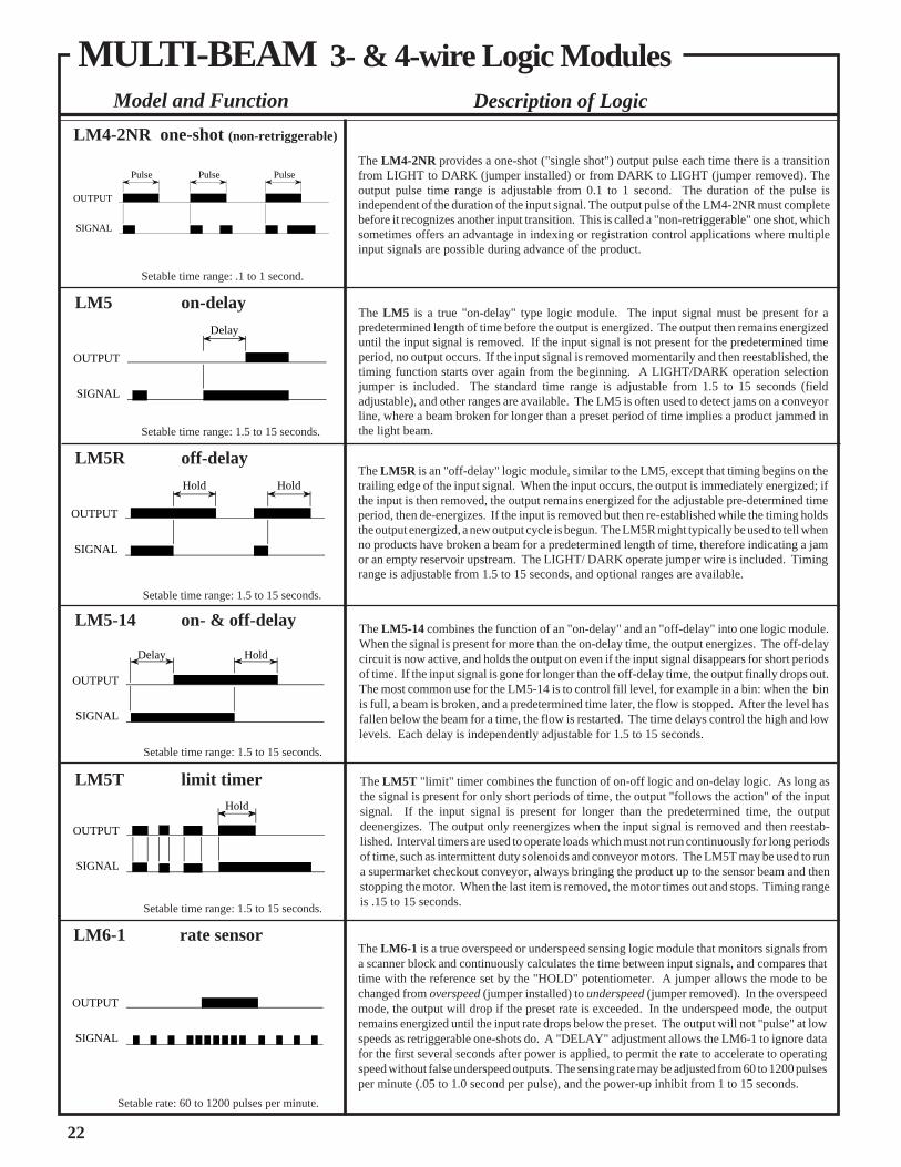
LM5 on-delay
LM5R off-delay
LM4-2NR one-shot (non-retriggerable)
LM5-14 on- & off-delay
LM5T limit timer
LM6-1 rate sensor
Setable time range: .1 to 1 second.
Setable time range: 1.5 to 15 seconds.
Setable time range: 1.5 to 15 seconds.
Setable time range: 1.5 to 15 seconds.
Setable time range: 1.5 to 15 seconds.
Setable rate: 60 to 1200 pulses per minute.
The LM5 is a true "on-delay" type logic module. The input signal must be present for apredetermined length of time before the output is energized. The output then remains energizeduntil the input signal is removed. If the input signal is not present for the predetermined timeperiod, no output occurs. If the input signal is removed momentarily and then reestablished, thetiming function starts over again from the beginning. A LIGHT/DARK operation selectionjumper is included. The standard time range is adjustable from 1.5 to 15 seconds (fieldadjustable), and other ranges are available. The LM5 is often used to detect jams on a conveyorline, where a beam broken for longer than a preset period of time implies a product jammed inthe light beam.
The LM5-14 combines the function of an "on-delay" and an "off-delay" into one logic module.When the signal is present for more than the on-delay time, the output energizes. The off-delaycircuit is now active, and holds the output on even if the input signal disappears for short periodsof time. If the input signal is gone for longer than the off-delay time, the output finally drops out.The most common use for the LM5-14 is to control fill level, for example in a bin: when the binis full, a beam is broken, and a predetermined time later, the flow is stopped. After the level hasfallen below the beam for a time, the flow is restarted. The time delays control the high and lowlevels. Each delay is independently adjustable for 1.5 to 15 seconds.
The LM5T "limit" timer combines the function of on-off logic and on-delay logic. As long asthe signal is present for only short periods of time, the output "follows the action" of the inputsignal. If the input signal is present for longer than the predetermined time, the outputdeenergizes. The output only reenergizes when the input signal is removed and then reestab-lished. Interval timers are used to operate loads which must not run continuously for long periodsof time, such as intermittent duty solenoids and conveyor motors. The LM5T may be used to runa supermarket checkout conveyor, always bringing the product up to the sensor beam and thenstopping the motor. When the last item is removed, the motor times out and stops. Timing rangeis .15 to 15 seconds.
The LM6-1 is a true overspeed or underspeed sensing logic module that monitors signals froma scanner block and continuously calculates the time between input signals, and compares thattime with the reference set by the "HOLD" potentiometer. A jumper allows the mode to bechanged from overspeed (jumper installed) to underspeed (jumper removed). In the overspeedmode, the output will drop if the preset rate is exceeded. In the underspeed mode, the outputremains energized until the input rate drops below the preset. The output will not "pulse" at lowspeeds as retriggerable one-shots do. A "DELAY" adjustment allows the LM6-1 to ignore datafor the first several seconds after power is applied, to permit the rate to accelerate to operatingspeed without false underspeed outputs. The sensing rate may be adjusted from 60 to 1200 pulsesper minute (.05 to 1.0 second per pulse), and the power-up inhibit from 1 to 15 seconds.
The LM5R is an "off-delay" logic module, similar to the LM5, except that timing begins on thetrailing edge of the input signal. When the input occurs, the output is immediately energized; ifthe input is then removed, the output remains energized for the adjustable pre-determined timeperiod, then de-energizes. If the input is removed but then re-established while the timing holdsthe output energized, a new output cycle is begun. The LM5R might typically be used to tell whenno products have broken a beam for a predetermined length of time, therefore indicating a jamor an empty reservoir upstream. The LIGHT/ DARK operate jumper wire is included. Timingrange is adjustable from 1.5 to 15 seconds, and optional ranges are available.
The LM4-2NR provides a one-shot ("single shot") output pulse each time there is a transitionfrom LIGHT to DARK (jumper installed) or from DARK to LIGHT (jumper removed). Theoutput pulse time range is adjustable from 0.1 to 1 second. The duration of the pulse isindependent of the duration of the input signal. The output pulse of the LM4-2NR must completebefore it recognizes another input transition. This is called a "non-retriggerable" one shot, whichsometimes offers an advantage in indexing or registration control applications where multipleinput signals are possible during advance of the product.
MULTI-BEAM 3- & 4-wire Logic Modules
OUTPUT
SIGNAL
OUTPUT
SIGNAL
Hold Hold
OUTPUT
SIGNAL
Pulse Pulse Pulse
OUTPUT
SIGNAL
Delay
OUTPUT
SIGNAL
Delay Hold
Hold
OUTPUT
SIGNAL
22
Model and Function Description of Logic
Setable time range: 1.5 to 15 seconds.
Setable time range: 1.5 to 15 seconds.
Setable time range: 1.5 to 15 seconds.
LM8A on-delay one-shot
LM10 ÷10 counter
LM8-1 delayed one-shot
LM8 repeat cycler
Model and Function Description of Logic
The LM8 is a repeat cycle timing module with independently adjustable delay and hold times.When an input signal is received from the scanner block, a delay period begins during which thereis no output. If the signal remains, the delay period is followed by a hold period, during whichthe output is energized. If the signal still remains, the hold period times out, releasing the outputand starting a new delay period. This sequence continues indefinitely until the input signal isremoved. The LM8 is used in edgeguide and other registration control schemes where it is desiredto "pulse" the correction motor to avoid overcorrection that might occur with a continuous output.Both time ranges are indpendently adjustable from 1.5 to 15 seconds. NOTE: use of the LIGHT/DARK operate jumper is reversed: remove for DARK, leave in place for LIGHT.
The LM8-1 is a delayed one-shot that functions very much like two individual one-shots, withthe end of the first initiating the second. When an input signal occurs, a delay period is initiated,during which time the output is not energized. After the delay, the output is energized for the holdperiod, then deenergized. No further action takes place unless the signal is removed and thenreestablished. This sequence is independent of the duration of the input signal. The LM8-1 isfrequently used to sense a product, and then act on that product a short time later when it is clearof the inspection station. An example might be to inspect cartons for open flaps, and to eject thefaulty cartons when they have completely passed the inspection point. Both time ranges areadjustable from 1.5 to 15 seconds.
The LM8A differs slightly from the LM8-1. It too incorporates both a delay and a hold time,except that the delay is a true on-delay. If the input signal does not last for the total duration ofthe delay time, no output action ever occurs (with the LM8-1, even a momentary signal generatesone complete cycle of timing). If the delay time passes, the one-shot output occurs, regardlessof what happens to the input signal. Removing the input signal and reapplying it begins a newcycle. The LM8A is used to eject a part that has remained in the sensor beam longer than the delaytime (for instance, a jammed part). Both time ranges are independently adjustable from 1.5 to15 seconds. NOTE: use of the LIGHT/ DARK operate jumper is reversed: remove for DARK,leave in place for LIGHT.
The LM10 is a fixed-count divide-by-ten logic module, with neither timing nor LIGHT/ DARKoperate functions. When power is first applied, the output is OFF; with each dark-to-lighttransition, the LM10 enters one count in its memory. After five counts, the output is energized,and it remains energized until the tenth count. It then deenergizes, and the sequence continues.The LM10 is intended for product counting applications using programmable logic controllersor computers, where the scan time of the input section of the controller is too slow to permit"catching" high speed count rates. It may also be used with electromechanical totalizers, whichsuffer from this same slow response. In operation, of course, the registered count must bemultiplied by ten to get the true count (ambiguity of five).
LMT is a plug-in test logic module for use when troubleshooting MULTI-BEAM sensors. Itcontains LED indicator lights in place of the timing potentiometers and a miniature switch in placeof the LIGHT/DARK operate jumper. The indicator lights display the operation of the scannerblock and power block to verify proper functioning, and the switch permits manual operation ofthe load to verify the output switching circuit. The step-by-step testing procedure included withthe LMT will allow a MULTI-BEAM to be completely tested without removing it from theinstallation, and, if there is a faulty scanner block, power block, or logic module, the LMT willidentify it. The LMT may also be used with all 2-wire MULTI-BEAMs (see pages 24 to 29).
LMTtestlogic
• For logic modules with a single timing function, specify the maximumdesired time in seconds (e.g., LM5M5 indicates an LM5 on-delay with the delaytime adjustable up to 5 seconds).
• For logic modules with dual timing functions, specify the maximum desireddelay and hold time in seconds (e.g., LM5-14M1M5 indicates an LM5-14 on-off delay with an on-delay adjustable up to 1 second and an off-delay adjustableup to 5 seconds). Always specify both timing ranges, even if only one is to bemodified.
• For fixed timing, the letter "F" should always be followed by the desired time,in seconds (e.g., LM5MF1 would be an LM5 on-delay with a fixed 1 seconddelay time). For fractions of seconds, use decimal equivalents, such asLM5MF.5, or LM5MF.01, etc.
Model Number Suffix Setable Time RangeM.01 .001 to .01 secondsM.1 .01 to .1 secondsM.5 .05 to .5 secondsM1 .1 to 1 secondM5 .5 to 5 secondsM15 1.5 to 15 seconds
Hold
OUTPUT
SIGNAL
Delay Delay DelayHold Hold
Hold
OUTPUT
SIGNAL
DelayDelay Hold
OUTPUT
SIGNAL
DelayHold
OUTPUT
SIGNAL
MULTI-BEAM 3- & 4-wire Logic Modules
23
The time ranges of any MULTI-BEAM 3- & 4-wire logic module may befactory modified. Time range modification is often necessary to improve thesetability of the timing function. Some time range modifications are carried instock. The current Banner products price list is the best source of thisinformation. Other time range modifications may be quoted. When orderingmodified logic modules, add the letter "M" after the model number, followedby the maximum time desired (in seconds). The table below lists possiblemodifications.
Logic Module Modifications

2-wire MULTI-BEAM
MULTI-BEAM 2-wire SensorsThe components of the MULTI-BEAM 2-wire family of modular self-containedsensors are physically identical to the 3- & 4-wire components. However, the 2-wire components are designed to wire directly in series with an ac load, exactlylike a limit switch. This design makes the 2-wire MULTI-BEAM impossible towire backward.
MULTI-BEAM 2-wire scanner blocks with their 10 millisecond response timehave approximately the same optical performance as the 1-millisecond 3- & 4-wire scanner block models.
The off-state leakage current of 2-wire MULTI-BEAM sensors is less than 1milliamp, the lowest value of any 2-wire photoelectric sensor. This makes theMULTI-BEAM 2-wire photoelectric device the most probable such device tointerface directly with ac inputs of programmable logic controllers (PLCs).
Functional Schematic, 2-wire MULTI-BEAM
24
ALIGNMENT INDICATOR: red LED on top of scanner block.Banner's exclusive, patented Alignment Indicating Device (AID™)circuit lights the LED whenever the sensor detects its own modulatedlight source, and pulses the LED at a rate proportional to the receivedlight level.
CONSTRUCTION: reinforced VALOX® housing with componentstotally encapsulated. Stainless steel hardware. Meets NEMA stan-dards 1, 3, 12, and 13.
OPERATING TEMPERATURE RANGE: -40 to +70 degrees C(-40 to +158 degrees F).
SUPPLY VOLTAGE: connections are made via a 2-wire powerblock (see page 27).
RESPONSE TIME: 10 milliseconds ON and OFF (3000 operationsper minute). NOTE: a built-in false pulse protection circuit holds theoutput off for 100 milliseconds after power is initially applied to thesensor.
REPEATABILITY OF RESPONSE: see individual sensor specs.
SENSITIVITY ADJUSTMENT: easily accessible, located on top ofscanner block beneath o-ring gasketed screw cover. 15-turn clutchedcontrol (rotate clockwise with a small screwdriver to increase gain).
SPECIFICATIONS
MULTI-BEAM2-Wire Scanner Blocks
Functional Schematic, 2-wire Scanner Block
Dimension Drawing,2-wire Scanner Block

Models Excess Gain Beam Pattern
2SBC1Focus at: 1.5inches
(38mm)
Model 2SBR1 receiver is used with the SBE emitter, which is the same emitter used with the 1 millisecond 3- &4-wire receiver model SBR1. The response time, however, is determined by the receiver, and is 10 milliseconds.This pair will work reliably in slightly dirty (average manufacturing plant) conditions up to 60 feet opposed, andoutdoors up to 20 feet. When more distance (or excess gain) is required, use 3- & 4-wire receiver model SBRX1with the SBEX emitter. The 2SBR1 will not work with the visible emitter SBEV. Use opposed mode sensors asa first choice in any application, except where the material to be sensed is translucent to light or so small that itwill not break the effective beam diameter. The SBE emiter uses a 3 & 4 wire power block. Powerblocks for usewith SBE include models PBA-1, PBB-1, PBD-1, PBT-1, and PBT48-1 (see pages 16 and 19 for information onthese powerblocks).
2SBC1-4Focus at: 4 inches
(10cm)Response: 10ms on/offRepeatability: 2.5msBeam: infrared, 940nm
2SBL1Range: 1 in. to 30 feet (2.5cm to 9m)Response: 10ms on/offRepeatability: 2.5msBeam: infrared, 940nm
SBE & 2SBR1
Range: 150 feet (45m)Response: 10ms on/offRepeatability: 0.03msBeam: infrared, 940nmEffective beam: 1" dia.
Model 2SBL1 is the retroreflective mode scanner block in the 2-wire MULTI-BEAM family. It has the sameexcellent optical performance as model SBL1 in the 3- & 4-wire family. If the application calls for breaking aretroreflective beam with shiny objects such as metal cans or cellophane-wrapped packages, mount the 2SBL1and its retroreflector at an angle of 10 degrees or more to the shiny surface to eliminate any direct reflections fromthe object itself, or consider using 3- & 4-wire scanner block model SBLVAG1 (page 8). Alternatively, the MAXI-BEAM, VALU-BEAM, and MINI-BEAM families offer 2-wire ac visible and polarized retroreflective models.Notice from the excess gain curve that the gain falls off at very close sensing ranges, so much so that retroreflectorscannot be used reliably closer than one inch from the sensor.
These convergent mode 2-wire scanner blocks are identical in performance to their 3- & 4-wire equivalents,except for the 10 millisecond response time. They are designed for 2-wire applications where background objectsmight be seen by proximity mode sensors, or where the precision of a small focused image is important (e.g.- edge-guiding or position control). Model 2SBC1 provides much more excess gain at its focus point as compared to thediffuse mode sensors. Convergent mode sensors are preferable to diffuse mode sensors if the distance from thesensor to the object to be detected can be kept constant. Models 2SBC1 and 2SBC1-4 may be derived from retromodel 2SBL1 by exchange of the upper cover assembly. Model 2SBC1 uses upper cover UC-C, and model2SBC1-4 uses upper cover model UC-C4. These may be interchanged. A 6-inch convergent model may be createdfrom either model by substituting upper cover UC-C6. See the Upper Cover Interchangeability Chart in theBanner product catalog for more information.
10
1
DISTANCE
100
1000
1 FT 10 FT 100 FT 1000FT
SBE &2SBR1E
XCESS
GAINI
10
1
DISTANCE
100
1000
.1 FT 1 FT 10 FT 100 FT
with BRT-3 3"reflector
with BRT-1 1"reflector
withBRT-Ttape
2SBL1EXCESS
GAINI
10
1
DISTANCE
100
1000
.1 IN 1 IN 10 IN 100 IN
Range based on 90%reflectance whitetest card
2SBC1
2SBC1-4
EXCESS
GAINI
300
0
INCHES
OPPOSED DISTANCE--FEET
60 90 120 150
20
40
60
20
40
60
SBE/2SBR1
0
0
2
4
6
2
4
6
6 12 18 24 32
INCHES
2SBL1
DISTANCE TO REFLECTOR--FEET
with BRT-3 reflector
0
0
INCHES
DISTANCE TO 90% WHITE TEST CARD--INCHES
.040
.080
.120
.040
.080
.120
1.5 3.0 4.5 6.0 7.5
2SBC1-42SBC1
MULTI-BEAM 2-wire Scanner Blocks
OBJECT
OBJECT
RETRO TARGET
OBJECT
OPPOSED Mode
RETROREFLECTIVE
CONVERGENT Mode
Sensing Mode
25
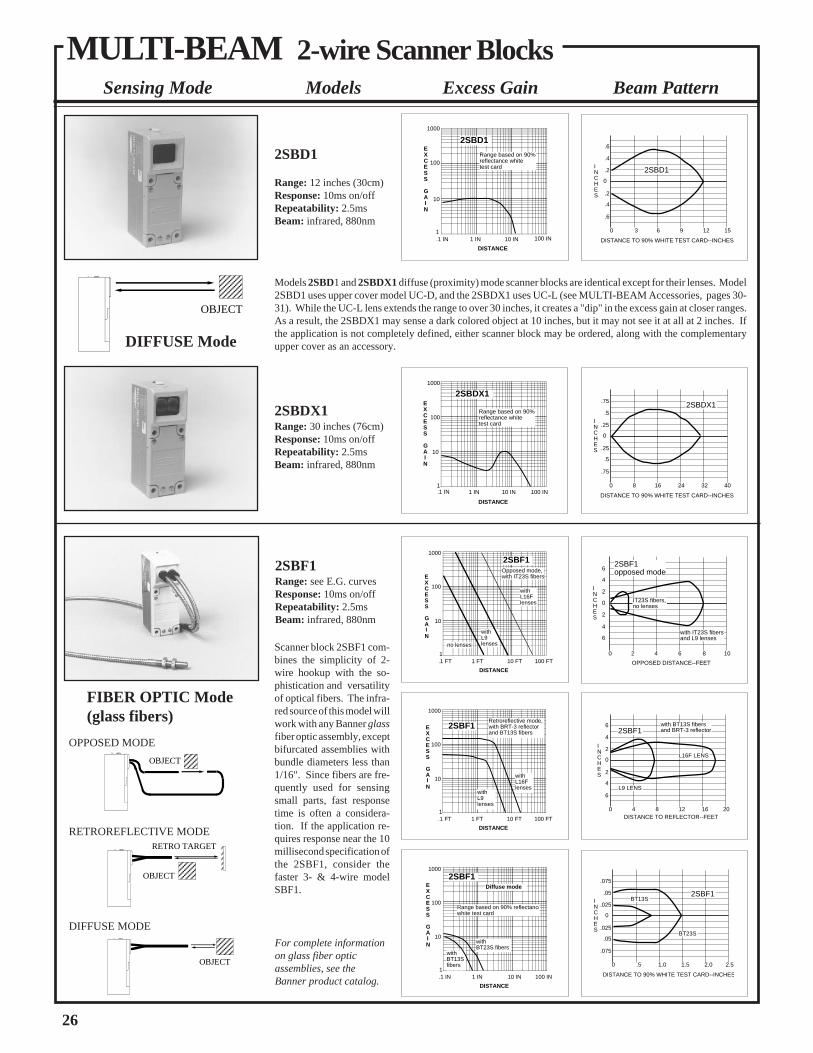
For complete informationon glass fiber opticassemblies, see theBanner product catalog.
Scanner block 2SBF1 com-bines the simplicity of 2-wire hookup with the so-phistication and versatilityof optical fibers. The infra-red source of this model willwork with any Banner glassfiber optic assembly, exceptbifurcated assemblies withbundle diameters less than1/16". Since fibers are fre-quently used for sensingsmall parts, fast responsetime is often a considera-tion. If the application re-quires response near the 10millisecond specification ofthe 2SBF1, consider thefaster 3- & 4-wire modelSBF1.
Models 2SBD1 and 2SBDX1 diffuse (proximity) mode scanner blocks are identical except for their lenses. Model2SBD1 uses upper cover model UC-D, and the 2SBDX1 uses UC-L (see MULTI-BEAM Accessories, pages 30-31). While the UC-L lens extends the range to over 30 inches, it creates a "dip" in the excess gain at closer ranges.As a result, the 2SBDX1 may sense a dark colored object at 10 inches, but it may not see it at all at 2 inches. Ifthe application is not completely defined, either scanner block may be ordered, along with the complementaryupper cover as an accessory.
10
1
DISTANCE
100
1000
.1 IN 1 IN 10 IN 100 IN
Range based on 90%reflectance whitetest card
2SBD1EXCESS
GAINI
10
1
DISTANCE
100
1000
Range based on 90%reflectance whitetest card
1 IN 10 IN 100 IN
2SBDX1
.1 IN
EXCESS
GAINI
10
1
DISTANCE
100
1000
.1 FT 1 FT 10 FT 100 FT
withL9lenses
withL16Flenses
Opposed mode,with IT23S fibers
2SBF1
no lenses
EXCESS
GAINI
10
1
DISTANCE
100
1000
.1 IN 1 IN 10 IN 100 IN
Diffuse mode
Range based on 90% reflectancewhite test card
withBT13Sfibers
withBT23S fibers
EXCESS
GAINI
2SBF1
10
1
DISTANCE
100
1000
.1 FT 1 FT 10 FT 100 FT
withL9lenses
withL16Flenses
Retroreflective mode,with BRT-3 reflectorand BT13S fibers
EXCESS
GAINI
2SBF1
0
0
DISTANCE TO 90% WHITE TEST CARD--INCHES
.2
.4
.6
.2
.4
.6
3 6 9 12 15
INCHES
2SBD1
0
0
DISTANCE TO 90% WHITE TEST CARD--INCHES
.25
.5
.75
.25
.5
.75
8 16 24 32 40
INCHES
2SBDX1
20
0
INCHES
OPPOSED DISTANCE--FEET
4 6 8 10
2
4
6
2
4
6with IT23S fibersand L9 lenses
IT23S fibers,no lenses
2SBF1opposed mode
0
0
2
4
6
2
4
6
4 8 12 16 20
INCHES
2SBF1
DISTANCE TO REFLECTOR--FEET
L9 LENS
L16F LENS
with BT13S fibersand BRT-3 reflector
0
0
DISTANCE TO 90% WHITE TEST CARD--INCHES
.025
.05
.075
.025
.05
.075
.5 1.0 1.5 2.0 2.5
INCHES
BT13S
BT23S
2SBF1
MULTI-BEAM 2-wire Scanner Blocks
DIFFUSE Mode
OBJECT
FIBER OPTIC Mode(glass fibers)
DIFFUSE MODE
OBJECT
OBJECT
RETRO TARGET
RETROREFLECTIVE MODE
OPPOSED MODE
OBJECT
2SBDX1Range: 30 inches (76cm)Response: 10ms on/offRepeatability: 2.5msBeam: infrared, 880nm
2SBF1Range: see E.G. curvesResponse: 10ms on/offRepeatability: 2.5msBeam: infrared, 880nm
2SBD1
Range: 12 inches (30cm)Response: 10ms on/offRepeatability: 2.5msBeam: infrared, 880nm
26
Beam PatternSensing Mode Models Excess Gain

L2L1V ac
(See Specifications)
1 2 LOAD
2PBBOperating voltage: 210 to 250V ac, 50/60Hz
Models
2PBAOperating voltage: 105 to 130V ac, 50/60Hz
2PBDOperating voltage: 22 to 28V ac, 50/60Hz
Output: SPST solid-state switch, 3/4 ampmaximum (derated to 1/2 amp at 70 degrees C).
Maximum inrush: 10 amps for 1 second(non-repeating).
On-state voltage drop: less than 10 volts
Leakage current: less than 1 milliamp(resistive or inductive loads)
MULTI-BEAM 2-wire power blocks offer the ultimate in simplicity of sensor hookup. They wiredirectly in series with an ac load, exactly like a limit switch. Response time of 2-wire powerblocks is determined by the scanner block, which is 10 milliseconds on/off. A built-in false pulseprotection circuit holds the output OFF for 100 milliseconds after power is initially applied to thepower block. 2-wire power blocks will operate from -40 to +70 degrees C (-40 to +158 degreesF). Resistive loads must be less than 15,000 ohms and inductive loads must be greater than 1.2watts (10 milliamps).
Additional specifications, both models:
2PBR (Electromechanical relay output)
Input: 105 to 130V ac, 50/60HzOutput: SPST electromechanical relay contact.
2PBR2 (Electromechanical relay output)
Input: 105 to 130V ac, 50/60HzOutput: SPDT electromechanical relay contacts,both contacts common to terminal #1 (L1).
Contact rating: 250V ac max, 30V dc max,5 amps max. (resistive load); install MOV acrosscontact if switching an ac inductive load.Closure time: 20 millisecondsRelease time: 20 millisecondsMaximum switching speed: 20 operations/secondMechanical life of relay: 10,000,000 operations
Connections
L2L1V ac
1 2
3 4
V ac/dc
LOAD
L2L1
1 2
3 4 LOAD
105 to 130V ac, 50/60Hz
LOAD
Model 2PBR actually requires a 4-wire hookup and model 2PBR2 requires a 3- or 4-wire hookup,even though they only work with 2-wire scanner blocks and logic modules. Both are powered by120V ac across terminals #1 and 2. The 2PBR offers an SPST "hard" relay contact betweenterminals #3 and 4. Model 2PBR2 is an SPDT version, with both contacts common to terminal#1: terminal #3 is a normally open output, and terminal #4 is normally closed. Theseconfigurations allow MULTI-BEAM sensors to directly interface large loads which draw morethan 3/4 amp like clutches, brakes, large contactors, and small motors. Model 2PBR can switchboth ac and dc loads; model 2PBR2 switches the ac line voltage to an ac load (see connectiondiagrams). The 2PBR and 2PBR2 also eliminate the problem of voltage drop from series stringsof sensors operating low voltage ac loads. NOTE: install an appropriate value MOV (metal oxidevaristor) transient suppressor across the power block relay contacts when switching an acinductive device.
Functional Schematics
MULTI-BEAM 2-wire power block models 2PBA, 2PBB, and 2PBD contain a low voltage power supply whichutilizes a unique circuit to take a very small leakage current through the load and convert it to the dc power requiredto run the scanner block and logic module. They also contain the solid-state switch that operates the load, and atransient suppression circuit to prevent false operation from high voltage spikes on the incoming line. They arecompletely solid-state for unlimited operating life.
Model 2PBR is a 4-wire power block which works with 2-wire scanner blocks and logic modules and offers an SPST"hard" contact for switching heavy ac or dc loads. Model 2PBR2, also for use with 2-wire scanner blocks and logicmodules, uses a 3- or 4-wire hookup with SPDT "hard" contacts for switching heavy ac loads.NOTE: MULTI-BEAM 2-wire ac power blocks are color-coded black.
MULTI-BEAM 2-wire Power Blocks
27

L1 L2
1 2
2PBA2PBB2PBD
V ac(See Specifications)
I
N
P
U
T
S
P
r
o
g.
C
r
t
l.
neutral
1
2
3
4
5
6
7
8
Hookuptypical for all
8 inputs
AC "hot" AC neutral
Hookup Diagrams for 2-wire Power Blocks (except models 2PBR & 2PBR2; see page 27)
NOTE: output has maximum load capacity of 3/4 amp; maximum resistive load 15K ohms, minimum inductive load 1.2 watts (10mA)
1CR relay will latch "on" whenever the 2-wireMULTI-BEAM output is energized. 1CR is resetwhen the normally-closed pushbutton switch ispressed.
MULTI-BEAM 2-wire sensors operate with verylow (1 milliamp) off-state leakage current. As aresult, they will interface directly to most PLCswithout the need for an artificial load resistor. Ifthe off-state voltage (1mA x input resistance ofthe PLC) is higher than the PLC sensing thresh-old, install a 10KΩ to 15KΩ, 5-watt resistor foreach 2-wire sensor. The resistor connects be-tween the input terminal and ac neutral.
If you have a question on hookup to a specificbrand of PLC, contact the Banner ApplicationsDepartment during normal business hours.
V ac(See Specifications)
L1 L2
2PBA2PBB2PBD
1 2
2PBA2PBB2PBD
1 2 LOAD
L1 L2
2PBA2PBB2PBD
1 2
V ac(See Specifications)
LOAD
L1 L2
2PBA2PBB2PBD
1 2
V ac(See Specifications)
LOAD
RESET
L1 L2
2PBA2PBB2PBD
1 2
V ac(See Specifications)
1CR
1CR
LATCH
MULTI-BEAM 2-wire sensors wire in series with an appropri-ate load. This combination, in turn, wires directly across the acline. A 2-wire sensor may be connected exactly like a mechani-cal limit switch.
The MULTI-BEAM remains powered when the load is "off" bya residual current which flows through the load. This off-stateleakage current is always less than 1 milliamp. The effect of thisleakage current depends upon the characteristics of the load. Thevoltage which appears across the load in the off-state is equal tothe leakage current of the sensor multiplied by the resistance ofthe load:
V (off)= 1mA x R(load)
If this resultant off-state voltage is less than the guaranteed turn-off voltage of the load, the interface is direct. If the off-statevoltage causes the load to stay "on", an artificial load resistormust be connected in parallel with the load to lower its effectiveresistance. Most loads, including most programmable logiccontroller (PLC) inputs, will interface to 2-wire sensors with1mA leakage current without the need for an artificial loadresistor. There is no polarity requirement. Either wire mayconnect to terminal #1, and the other to terminal #2.
CAUTION: all three components of a MULTI-BEAM 2-wiresensor will be destroyed if the load becomes a short circuit!!
V ac(See Specifications)
L1 L2
LOAD
2PBA2PBB2PBD
1 2
Basic Hookup of 2-wire MULTI-BEAMMultiple 2-wire MULTI-BEAMs may be wired together inparallel to a load for "OR" or "NAND" logic functions.When sensors are wired in parallel, the off-state leakagecurrent through the load is equal to the sum of the leakagecurrents of the individual sensors. Consequently, loads withhigh resistance, like small relays and electronic circuits, mayrequire artificial load resistors.
2-wire MULTI-BEAM sensors have a 100 millisecondpower-up delay for protection against false outputs. When2-wire MULTI-BEAMs are wired together in parallel, anypower block which has an energized output will rob all of theother power blocks of the current they need to operate.When the energized output drops, there will be a 0.1 seconddelay before any other MULTI-BEAM can energize. As aresult, the load may momentarily drop out.
2-wire MULTI-BEAM sensors cannot wire in series withother 2-wire sensors unless power block model 2PBR isused. If series connection of 2-wire ac sensors is required,consider models within the VALU-BEAM or MINI-BEAMfamilies.
2-wire MULTI-BEAMs in Parallel
2-wire MULTI-BEAMin Series with Contacts
2-wire MULTI-BEAMin Parallel with Contacts
When 2-wire MULTI-BEAM sensors are con-nected in series with mechanical switch or relaycontacts, the sensor will receive power to operateonly when all of the contacts are closed. Thefalse-pulse protection circuit of the MULTI-BEAM will cause a 0.1 second delay between thetime that the last contact closes and the time thatthe load can energize.
2-wire MULTI-BEAM sensors may be wired inparallel with mechanical switch or relay con-tacts. The load will energize when any of thecontacts close or the sensor output is energized.When a contact is closed, it shunts the operatingcurrent away from the MULTI-BEAM. As aresult, when all of the contacts are open, theMULTI-BEAM's 0.1 second power-up delaymay cause a momentary drop-out of the load.
Photoelectric Latch withManual Reset
Hookup of 2-wire MULTI-BEAM to a Programmable Logic Controller (PLC)
MULTI-BEAM 2-wire Power Blocks
28

2LM4-2 one-shot
2LM5R off-delay
2LM5 on-delay
2LM5-14 on- and off-delay
2LM5T limit timer
Setable time range: 1.5 to 15 seconds.
2-wire logic modules provide the mechanical and electrical connection between the scannerblock and the power block of a 2-wire MULTI-BEAM sensor. In addition, the logic module
Setable time range: 1.5 to 15 seconds.
Setable time range: 1.5 to 15 seconds.
Setable time range: 1.5 to 15 seconds.
Setable time range: .1 to 1 second.
MULTI-BEAM 2-wire Logic Modules
The 2LM3 is an on/off logic module that has the ability to be programmed for either LIGHTor DARK operate. It comes with a jumper wire installed: with the jumper in place, the outputis DARK operated; with the jumper removed, the output is LIGHT operated. The 2LM3 isused when no timing function is desired.
The 2LM4-2 provides a one-shot ("single shot") output pulse each time there is a transitionfrom LIGHT to DARK (jumper installed) or from DARK to LIGHT (jumper removed). Theoutput pulse time range is from adjustable from 0.1 to 1 second. The duration of the pulseis independent of the duration of the input signal. The timing of the 2LM4-2 is restarted eachtime the input signal is removed and then recurs. This is referred to as a "retriggerable" oneshot, and this feature may be applied to some rate sensing applications.
The 2LM5 is a true "on-delay" type logic module. The input signal must be present for apredetermined length of time before the output is energized. The output then remainsenergized until the input signal is removed. If the input signal is not present for thepredetermined time period, no output occurs. If the input signal is removed momentarilyand then reestablished, the timing function starts over again from the beginning. Thestandard time range is adjustable from 1.5 to 15 seconds, and other ranges are available.
The 2LM5R is an "off-delay" logic module, similar to the 2LM5, except that timing beginson the trailing edge of the input signal. When the input occurs, the output is immediatelyenergized; if the input is then removed, the output remains energized for the adjustablepredetermined time period, then deenergizes. If the input is removed but then reestablishedwhile the timing holds the output energized, a new output cycle is begun. The LIGHT/DARK operate jumper wire option is included. Timing range is adjustable from 1.5 to 15seconds, and op-tional ranges are available.
The 2LM5-14 combines the function of an "on-delay" and an "off-delay" into one logicmodule. When the signal is present for more than the output on-delay time, the outputenergizes. The off delay circuit is now active, and holds the output on even if the input signaldisappears for short periods of time. If the input signal is gone for longer than the off-delaytime, the output finally drops out. The time delays can control high and low levels in flowcontrol applications. Each delay is independently adjustable for 1.5 to 15 seconds.
The 2LM5T "limit" timer combines the function of on-off logic and on-delay logic. As longas the signal is present for only short periods of time, the output "follows the action" of theinput signal. If the input signal is present for longer than the predetermined time, the outputdeenergizes. The output only reenergizes when the input signal is removed and thenreestablished. Interval timers are used to operate loads which must not run continuously forlong periods of time, such as intermittent duty solenoids and conveyor motors. Timingrange is adjustable from 1.5 to 15 seconds.
Description of LogicModel and Function
provides the LIGHT/DARK program-ming of the output plus delay or pulsetiming, if required. 2-wire logic mod-ules are all color-coded black (3- and4-wire logic modules are red). Thetiming ranges listed below are stan-dard. Special timing ranges are avail-able, on a quote basis, per the instruc-tions given for 3- and 4-wire logicmodules on page 23. NOTE: modelLMT test module (page 23) may alsobe used with 2-wire systems.
SPECIFICATIONS, 2-WIRE LOGIC MODULES:specifications for 2-wire logic modules are identical to those for 3- and 4-wire logic modules (see page 21).
OUTPUT
SIGNAL
Delay
OUTPUT
SIGNAL
Hold Hold
OUTPUT
SIGNAL
Delay Hold
Hold
OUTPUT
SIGNAL
OUTPUT
SIGNAL
OUTPUT
SIGNAL
Pulse Pulse
Hold
2LM3 on-off
29

UC-LUsed on:SBESBEVSBEXSBR1SBRX1SBL1SBLV1, SBLX1, SBDL1, SBDX1, SBAR1,SBAR1GH, 2SBR1, 2SBL1, 2SBDX1,3GA5-14, EM3T-1M, R1T3
UC-DUsed on:SBD1SBEDSBRD1SBEXDSBRXD12SBD1
Flat vinyl lensfor short range and/or wide beam angle.
Standard replacement cover for all scanner blocks.
LCMB LCMBMTA
"MTA" = Modified Timing Access. Gasketed nylonscrew covers for logic module timing adjustments.
30
Replaces UC-L in sensing locations where highlycaustic materials are present (e.g. acid vapor orsplash). Glass lens.
Anti-glare (polarizing) filter for retroreflectivesensing of shiny objects.
Adds plastic dust cover to UC-L. Used when sensoris mounted facing up (used to prevent dust/dirtbuildup on lens).
Identical to UC-D, but with addition of plastic dustcover to prevent accumulation of dust/dirt in lensarea.
UC-LAG(Used onSBLVAG1)
UC-LJUC-DJ UC-LG
These upper covers are used in special sensing environments.
For fiberoptic emitter-only scanner blocks. For fiberoptic receiver-only scanner blocks.
UC-EFUsed on:SBEFSBEXF
UC-RFUsed on:SBRF1SBRXF1SBAR1GHF
UC-F(Used on:SBF1,SBF1MHS,SBFX1,SBFV1,2SBF1).
Fits all Banner fiberoptic assemblies.
UC-C 1.5 inch (38mm) focus, glass lensesUC-C4 4 inch (10cm) focus, glass lensesUC-C6 6 inch (15cm) focus, glass lenses
"MB" = Modified with Baffle; for short-range proxi-mity mode with SBDX1.
UC-DMB(Used onSBDX1MD)
MULTI-BEAM Accessories
Lower Covers
Replacement lower covers fit all MULTI-BEAM scanner blocks. Lower coversinclude gaskets and four stainless steelmounting screws.
Special Upper Covers
An upper cover consists of the optical element for the MULTI-BEAM which is built into a gasketed cover for the upper portion of the scannerblock. Upper covers may be ordered as replacement parts or for modifying the optical response of a particular model scanner block. Thefollowing upper cover assemblies are standard and stocked. Other special variations may be quoted. Stainless steel hardware is included witheach cover. NOTE: See the MULTI-BEAM Accessories section of the Banner product catalog for information on interchangeability of uppercovers between various scanner block models.
Upper Covers (Lens Assemblies)

MBCC-412
RF1-2NPS
MBC-4
Model SMB700 (right) is a general-purpose two-axis mount-ing bracket that is supplied with a cable gland assembly whichis used to attach the MULTI-BEAM wiring base to the bracket.The gland assembly is threaded through the bracket and into theconduit entrance at the base of the scanner block. A large lock-washer is supplied to hold the scanner block firmly in place. Thebracket is 11-gauge zinc plated steel.
Mounting Brackets
Cable gland assembly for MULTI-BEAMs. Includes cordgrips for .1 to .4 inch diameter cable. Bracket lockwasheris also included.
MBC-4 is a 4-pin male industrial-duty connector thatthreads into the base of all MULTI-BEAMs. MBCC-412is a 12-foot long (3,6m) "SJT" type cable. It is interchange-able with standard industry types of several different manu-facturers.
Heavy-duty 1/4-inch (6mm) zinc platedsteel bracket that allows the MULTI-BEAM to retrofit to installations ofMICRO-SWITCH models MLS8 orMLS9 sensors. Includes cable glandand lockwasher.
Heavy duty 1/4-inch (6mm) zinc platedsteel bracket that allows the MULTI-BEAM to retrofit to installations ofPHOTOSWITCH series 42RLU and42RLP sensors. Includes cable glandand lockwasher.
31
SMB700
SMBLS
MULTI-BEAM Accessories
SMB700P
Model SMBLS (right) is a two-partbracket assembly which allows adjust-ment in three directions. It consists oftwo 11-gauge zinc plated steel right-angle brackets which fasten together sothat they rotate relative to each other.The MULTI-BEAM wiring base at-taches to the upper bracket and slots areprovided for vertical adjustment. Thebottom bracket is a modified version ofthe SMB700. Assembly hardware and acable gland are included.
Model SMB700SS is an 11-gauge stainless steel version of theSMB700. It is sold alone, without the cable gland assembly andlockwasher.
Model SMB700F (photo, below) is a flat, single-axis versionof the SMB-700. It is sold without hardware.
SMB700M

WARRANTY: Banner Engineering Corporation warrants its products to be free from defects for one year. Banner Engineering Corporation will repair or replace,free of charge, any product of its manufacture found to be defective at the time it is returned to the factory during the warranty period. This warranty does notcover damage or liability for the improper application of Banner products. This warranty is in lieu of any other warranty either expressed or implied.
!WARNING The photoelectric presence sensors described in this catalog do NOT include the self-checkingredundant circuitry necessary to allow thier use in personnel safety applications. A sensor failure or malfunction can resultin either an energized or a de-energized sensor output condition.
Never use these products as sensing devices for personnel protection. Their use as a safety device may create an unsafecondition which could lead to serious injury or death.
Only MACHINE-GUARD and PERIMETER-GUARD Systems, and other systems so designated, are designed to meet OSHA and ANSImachine safety standards for point-of-operation guarding devices. No other Banner sensors or controls are designed to meet these standards,and they must NOT be used as sensing devices for personnel protection.
Banner Engineering Corp. 9714 Tenth Ave. No. Minneapolis, MN 55441 Telephone: (612)544-3164 FAX (applications): (612)544-3573