limits, fits and tolerances -...
TRANSCRIPT

Limits, Fits and tolerances
Metrology and Instrumentation
Dr. Belal Gharaibeh
November 27, 2011
UJ 1
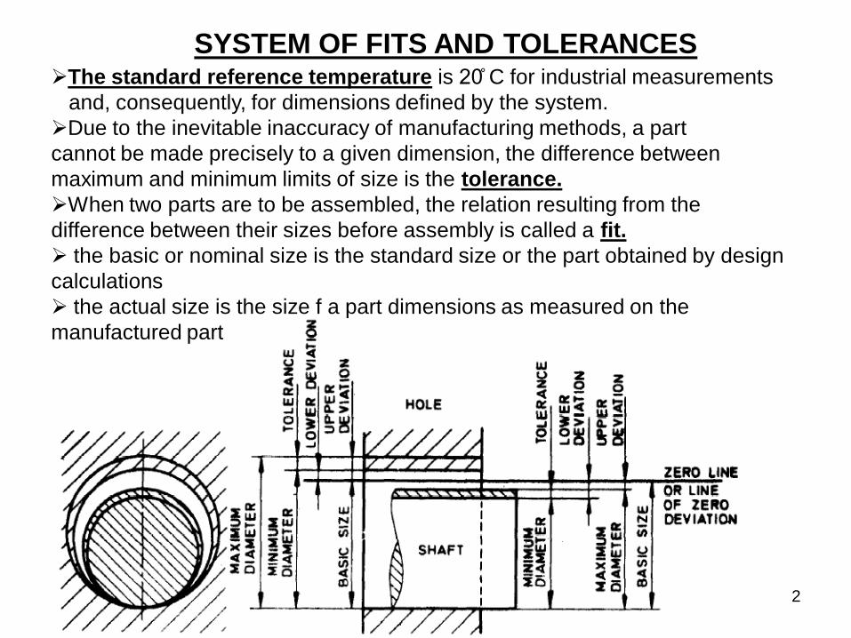
SYSTEM OF FITS AND TOLERANCES The standard reference temperature is 20̊ C for industrial measurements
and, consequently, for dimensions defined by the system.
Due to the inevitable inaccuracy of manufacturing methods, a part
cannot be made precisely to a given dimension, the difference between
maximum and minimum limits of size is the tolerance.
When two parts are to be assembled, the relation resulting from the
difference between their sizes before assembly is called a fit.
the basic or nominal size is the standard size or the part obtained by design
calculations
the actual size is the size f a part dimensions as measured on the
manufactured part
2

Why do we need limits, fits and tolerances?
• Reasons for imperfect dimensions
– temperature variation during machining
– Tool wear
– Deflection and vibration within the
machine/work/human interface
– Cost of manufacturing increases with
increased tolerance demand
3

Interchangeable manufacturing
• There is a need to select random parts during assembly,
therefore dimensions should be within certain limits to make
interchangeable manufacturing, this is achieved only if:
1. The type of fit which is required between mating parts
2. The tolerance which is to be allowed upon each dimension
Most products have many
Parts with variable sizes and shapes
Therefore, each part has to match the
other parts
Without empty spaces or hard to fit
problems
4

CLEARANCE FIT
Maximum shaft dimension < Minimum hole dimension
FIT - condition of looseness or tightness between two mating parts being
assembled together
5

INTERFERANCE FIT
Maximum Hole size < Minimum Shaft size 6

TRANSITION FIT
Obtained by overlapping of tolerance zones of shaft and hole
……Does not guarantee neither clearance nor interference fit 7

HOLE BASED SYSTEM-
Size of hole is kept constant,
shaft size is varied
to get different fits.
To obtain different types of fits, it is general practice to
vary tolerance zone of one of the mating parts
SHAFT BASED SYSTEM-
Size of shaft is kept constant,
hole size is varied
to get different fits.
8

A fit is indicated by the basic size common to both components, followed by
symbol corresponding to each component, the hole being quoted first.
E.g. 45 H8/g7
9

H : lower deviation of
hole is zero
h : upper deviation of
shaft is zero
E.S. – upper deviation
E.I. – lower deviation
Representation of
Tolerance
1) Letter Symbol
The selection of letter freezes
one limit of hole / shaft
(how much away from Basic
size)
45 E8/e7 Basic Size
One can have different
possible combinations; eg.
45H6g7, 45H8r6, 45E5p7
10

Representation of Tolerance
2) Number or Grade
IT01, IT0, IT1,….IT16
Tolerance Grade defines range of
dimensions (dimensional variation)
There are manufacturing
constraints on tolerance grade
chosen
11

H : lower deviation of
hole is zero
Representation of
Tolerance
The selection of
Tolerance grade number
freezes the other limit of
hole / shaft
12

Together (Letter & Grade)
on both mating
components decide quality
of fit
H7 : Tol Grade 7 mean 21μ variation
(H means upper deviation zero)
Representation of Fit
0.021
0.022 0.013
Φ30.000
Φ30.021
Φ30.022
Φ30.035
p6 : Tol Grade 6 means 13μ variation
(p means upper deviation is 22 μ)
INTERFERENCE
FIT
13

Tolerance on Components
14

15

•The upper deviation or the upper limit of size
shall be written in the upper position and the lower
deviation or the lower limit of size in the lower
position, irrespective of whether a hole or a shaft is
toleranced.
•The tolerance symbol for the
hole shall be placed before that
for the shaft or above it, the
symbols being preceded by the
basic size indicated once only.
Indication of Tolerances on Angular Dimensions
16