lime treatment of acid mine drainage in canada - infomine
TRANSCRIPT

The Science of Treating Acid Mine Drainage and Smelter Effluents
By Bernard Aubé, P. Eng., M.A.Sc.
EnvirAubé 361 Aumais, Ste-Anne-de-Bellevue
Québec, Canada, H9X 4A9 [email protected] www.enviraube.com

Table of Contents
INTRODUCTION..................................................................................................................................................... 1 1.0 The Basic Science of Lime Treatment ......................................................................................................... 1
1.1 Neutralisation and Precipitation ............................................................................................................... 1 1.2 Aeration/Oxidation................................................................................................................................... 3
2.0 Lime Treatment Processes............................................................................................................................ 3 2.1 Pond Treatment ........................................................................................................................................ 4 2.2 Pit Treatment............................................................................................................................................ 5 2.3 In-line Treatment and Co-deposition ....................................................................................................... 6 2.4 Conventional Treatment Plant.................................................................................................................. 7 2.5 Simple Sludge Recycle ............................................................................................................................ 8 2.6 HDS Process ............................................................................................................................................ 9 2.7 Geco Process .......................................................................................................................................... 12 2.8 Staged-Neutralization Process................................................................................................................ 13
3.0 Comparisons Between Processes................................................................................................................ 14 3.1 Heath Steele Pilot Tests ......................................................................................................................... 14 3.2 CANMET Pilot Tests............................................................................................................................. 15
4.0 Scaling Issues ............................................................................................................................................. 15 4.1 Gypsum .................................................................................................................................................. 15 4.2 Calcite .................................................................................................................................................... 16
5.0 Arsenic Treatment ...................................................................................................................................... 17 6.0 Molybdenum Treatment ............................................................................................................................. 18 7.0 Sludge Disposal .......................................................................................................................................... 18 8.0 Cost Effectiveness of Treatment................................................................................................................. 19 9.0 Conclusion.................................................................................................................................................. 20 10.0 References .................................................................................................................................................. 20

INTRODUCTION Although many different biological and chemical technologies exist for treatment of acid mine drainage (AMD) and smelter effluents, lime neutralisation remains by far the most widely applied treatment method. This is largely due to the high efficiency in removal of dissolved heavy metals combined with the fact that lime costs are low in comparison to alternatives. Lime treatment essentially consists in bringing the pH of the raw water to a point where the metals of concern are insoluble. These metals therefore precipitate to form minuscule particles. A separation of these precipitates is then required to produce a clear effluent which meets regional discharge criteria. The solid/liquid separation forms a sludge which, depending on the applied process, can contain 1 to 30% solids by weight. This sludge must be disposed of in an environmentally acceptable manner. The basic chemistry of neutralisation is described here. Different types of lime neutralisation processes, including their respective strengths and weaknesses, are also discussed. The evaluated processes are linked to concrete examples of existing treatment systems throughout the world. Scaling issues, often an important cost to operators, are also described. Some contaminants are not easily treated simply by controlling pH with lime and separating precipitates. This is the case for arsenic and molybdenum, for example. These two contaminants must be co-precipitated with other metals, typically ferric iron. The treatment systems for these differ from typical AMD treatment and are also discussed here. 1.0 The Basic Science of Lime Treatment
1.1 Neutralisation and Precipitation The principle of lime neutralisation of acid mine drainage (AMD or ARD for acid rock drainage) lies in the insolubility of heavy metals in alkaline conditions. By controlling pH to a typical setpoint of 9.5, metals such as iron (Fe), zinc (Zn), and copper (Cu) are precipitated (see Figure 1). Other metals such as nickel (Ni) and cadmium (Cd) require a higher pH, in the range of 10.5 to 11 to effectively precipitate the hydroxides. The precipitates can be formed individually as minuscule particles smaller than a single micron (1 µm). In a high-density sludge (HDS) process, the precipitates are formed onto existing particles recycled within the process. This creates larger and denser particles that can settle and compress better than the typical precipitates. This essentially defines the greatest difference between lime treatment processes: the method of precipitating and separating the solids and the sludge that is formed. The resulting effluent chemistry is similar for all lime treatment processes.
1

Figure 1: Metal Hydrolysis (from Aubé and Zinck, 2003)
Lime dissolution is the first step of the neutralisation process. For large treatment systems, quicklime is used. This lime must first be hydrated (slaked) and is normally fed to the process as a slurry. The hydrated lime then dissolves to increase pH. The two following equations illustrate these reactions:
CaO + H2O ⇒ Ca(OH)2 Ca(OH)2 ⇒ Ca2+ + 2OH-
The increased pH then provides hydroxide ions which combine with the dissolved metals to produce precipitates. The following equations show the precipitation reactions with different metals:
Al3+ + 3OH- ⇒ Al(OH)3 Co2+ + 2OH- ⇒ Co(OH)2
Cu2+ + 2OH- ⇒ Cu(OH)2 Fe2+ + 2OH- ⇒ Fe(OH)2 Fe3+ + 3OH- ⇒ Fe(OH)3
Ni2+ + 2OH- ⇒ Ni(OH)2
Pb2+ + 2OH- ⇒ Pb(OH)2 Zn2+ + 2OH- ⇒ Zn(OH)2
2

1.2 Aeration/Oxidation Among the metals shown above is ferrous iron (Fe2+). Ferrous hydroxides are not as stable as ferric hydroxides when the sludge is exposed to acidic waters or natural precipitation. For this reason, aeration is often applied to oxidise the iron to the more stable form, as per the following equation:
Fe(OH)2 + ½ H2O + ¼ O2 ⇒ Fe(OH)3 Ferrous hydroxides also do not settle as well as ferric and can create a highly viscous sludge. There are therefore three major advantages for proper oxidation of iron: 1) sludge stability, 2) treatment efficiency, and 3) sludge viscosity. That being said, it is possible to operate a successful treatment plant without aeration or even complete oxidation of iron. Incomplete oxidation does not have much effect on a low-density sludge (LDS) plant as the low solids content causes very little viscosity. The viscosity issue is for HDS processes and not conventional or pond treatment. In the LDS treatment systems, it may be necessary to raise the pH higher than with an aerated system as ferrous hydroxides precipitate at a higher pH (Figure 1). At that higher pH, the treatment efficiency can still be acceptable. There are also many sites that do not require aeration to oxidise ferrous iron, even though it is present. For example, testing at Heath Steele has shown that more than 200 mg/L of ferrous iron can be oxidized without aeration (Aubé, 2004a). Actual plant tests at other sites have also shown this same result (Aubé, 1999). Unfortunately, it is often considered standard procedure to put in an aeration system whenever a treatment plant is built at a site where iron is present. This is a mistake not only because of the additional capital costs, but also because of increased operating costs. An aerated reactor requires blowers and more horsepower for agitation, both of which consume considerable amounts of electricity. Maintenance of these items is also expensive over the life of the plant. Prior to constructing a full-scale treatment plant, pilot plant tests should be used to verify whether aeration is truly necessary for your site. If the raw water quality changes in the years to come, aeration can always be added when it becomes necessary. 2.0 Lime Treatment Processes The following sub-sections explain the concept and discuss advantages and disadvantages of different treatment processes. The processes are in order of the simplest to the most complex and recent systems. The older methods use lime less efficiently and do not allow for good control of the treatment system. The more recent processes require a greater capital investment but are considerably more efficient for lime usage and waste production. The metal precipitates created during all processes are wastes identified as sludge. This sludge must be disposed of in an environmentally acceptable manner. As sludge disposal costs can be important, the most advanced processes minimise the volumes by creating a higher-density sludge. The sludge disposal and lime costs over the long term usually justify a more important capital investment due to significant savings in operating costs.
3

2.1 Pond Treatment This treatment system entails adding lime in a stream or mixing system and allowing the precipitates to settle in a pond. The pond is often divided into a primary and secondary section. The primary pond serves to accumulate the precipitated sludge and can quickly be filled. These often require yearly dredging of sludge which then requires a storage area. The secondary pond is larger and requires a long retention time with laminar conditions to allow for “polishing” of the effluent.
AMD
LIME
SLUDGE
EFFLUENT
CO2
Settling Pond
Figure 2: Pond Treatment
Pond treatment systems are often chosen for their simplicity and low capital costs when land is available. They can be used to treat very high flowrates and even important concentrations of metals but require a very large surface area when doing so. Treating AMD in a pond does not allow for much control of the system and thus can be more problematic than other types of treatment systems. For example, it is difficult to oxidise ferrous iron when present because aeration for oxidation to ferric iron requires proper mixing and contact time. If air is sparged in a pond, the sludge cannot settle. Another difficulty is that the flowrate is normally not controlled when treating in a pond. Pond treatment systems are typically designed to use natural depressions along the flow path of the site drainage for treatment. To control the flowrate, an upstream retention pond, and either a pumping or a gate system would be required. This increases the capital requirements and decreases the advantages of such a system. The lack of control typical of such systems reduces treatment efficiency during high flowrates unless other measures are taken to improve the treatment capacity. Without a feed flowrate control system, the AMD continues to enter the pond even if the lime system is down. This can upset the entire pond and result in a non-compliant discharge. It may also be impossible to shut the system down in times of high wind. Wind effects can cause turbulence in the polishing section of the pond which in turn causes re-suspension of sludges and/or prevents settling of fresh precipitates. Probably the greatest disadvantage of pond treatment systems is their low lime efficiency. A system that uses in-stream addition without any mechanical mixing may have less than 50% efficiency in lime dissolution. By using an agitator and pH control system, the lime usage efficiency increases significantly. Nevertheless, these systems cannot compare with high-density systems where sludge recycling ensures that unreacted lime be used due to repetitive contact with AMD.
4

To ensure proper treatment in a pond system, the pH setpoint is often brought up much higher than is necessary for the targeted metal(s). For example, some pond systems for treating dissolved Zn often control the pH to more than 10.5, when HDS systems can efficiently remove Zn from solution at a pH of 9.3. As the local effluent regulations sometimes stipulate a maximum pH of 9.5, the pH must then be reduced before final discharge from a pond system. This is most often done with the addition of carbon dioxide, although some sites use sulphuric acid. In order to improve both lime efficiency and treatment efficiency, a sludge recycle system can be installed. Tests completed at Falconbridge, Kidd Mining Division showed that recycling sludge using an automated dredge would decrease overall treatment costs (Aubé, 2004c). This decrease is due primarily to lime savings as all unused lime is recycled and reacted upon subsequent contact. The lower lime consumption is also a result of a lower operating pH as the added solids increase the efficiency of precipitation and settling, thereby allowing a lower pH setpoint. This lower setpoint also reduces the carbon dioxide consumption for pH modification at the tail end of the process. A third cost advantage is the formation of less sludge. Sludge dredging is a significant yearly cost to Kidd Mining Division. Lime represents nearly half the sludge and re-using it means that the sludge production will be greatly reduced. It is also theorised (though not yet proven) that a recycle would increase the sludge density, thus further reducing dredging costs.
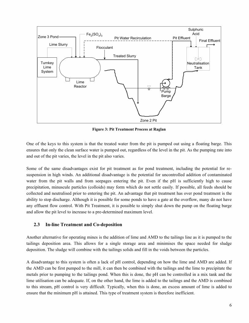
2.2 Pit Treatment Treating AMD in a pit is similar to pond treatment but generally requires pumping into and/or out of the pit. As with pond treatment, mechanical mixing will significantly increase lime efficiency. Treating AMD in a pit can be done using batch treatment or continuous treatment. Batch treatment is done by allowing contaminated water into the pit to a level just below that which would allow seepage out of it. At this point, the pit water is contacted with an alkali (lime or caustic soda, for example) through either recirculation of the pit water or uniform distribution of the alkali. Once the target pH is attained, the sludge is allowed to settle quiescently to the bottom. The clear supernatant is then pumped out and neutralised with sulphuric acid or carbon dioxide if necessary. Once the pit level is brought down to just above the sludge bed, the procedure is re-started. At Falconbridge’s Raglan Division (SMRQ – Société Minière Raglan du Québec), a Ni mine in Northern Québec, a continuous pit treatment process is applied (Aubé and Arseneault, 2003). Treatment is completed by pumping the drainage to a tank, where pH is controlled by adding hydrated lime to a pH of about 11 (Figure 3). This drainage is essentially neutral, but contains Ni at concentrations higher than that allowed for discharge. For better solid/liquid separation, ferric sulphate and a flocculant can be added for coagulation and flocculation, respectively. The treated slurry is then discharged underwater at one end of the pit to promote settling of the fresh particles. A clear supernatant is pumped out from the opposite end of the pit. The effluent is then neutralised to pH 9.2 using sulphuric acid prior to release (Aubé and Arseneault, 2003). In the spring, when the pit water is contaminated, it is possible to recirculate the water and treat the entire pit volume before pumping from other sources.
5
LimeReactor
TurnkeyLime
System
Zone 3 Pond
Lime Slurry
Treated Slurry
PumpBarge
NeutralisationTank
Pit Effluent
SulphuricAcid
Final EffluentPit Water Recirculation
Zone 2 Pit
Fe2(SO4)3
Flocculant
Figure 3: Pit Treatment Process at Raglan
One of the keys to this system is that the treated water from the pit is pumped out using a floating barge. This ensures that only the clean surface water is pumped out, regardless of the level in the pit. As the pumping rate into and out of the pit varies, the level in the pit also varies. Some of the same disadvantages exist for pit treatment as for pond treatment, including the potential for re-suspension in high winds. An additional disadvantage is the potential for uncontrolled addition of contaminated water from the pit walls and from seepages entering the pit. Even if the pH is sufficiently high to cause precipitation, minuscule particles (colloids) may form which do not settle easily. If possible, all feeds should be collected and neutralised prior to entering the pit. An advantage that pit treatment has over pond treatment is the ability to stop discharge. Although it is possible for some ponds to have a gate at the overflow, many do not have any effluent flow control. With Pit Treatment, it is possible to simply shut down the pump on the floating barge and allow the pit level to increase to a pre-determined maximum level.
2.3 In-line Treatment and Co-deposition Another alternative for operating mines is the addition of lime and AMD to the tailings line as it is pumped to the tailings deposition area. This allows for a single storage area and minimises the space needed for sludge deposition. The sludge will combine with the tailings solids and fill in the voids between the particles. A disadvantage to this system is often a lack of pH control, depending on how the lime and AMD are added. If the AMD can be first pumped to the mill, it can then be combined with the tailings and the lime to precipitate the metals prior to pumping to the tailings pond. When this is done, the pH can be controlled in a mix tank and the lime utilisation can be adequate. If, on the other hand, the lime is added to the tailings and the AMD is combined to this stream, pH control is very difficult. Typically, when this is done, an excess amount of lime is added to ensure that the minimum pH is attained. This type of treatment system is therefore inefficient.
6

Villachica et al. published a process option where the AMD is combined with tailings prior to adding lime. This process attempts to take advantage of the neutralising potential of the tailings and reduce lime consumption. The disadvantage of this system is that the neutralising potential is consumed, thereby leaving the tailings more susceptible to oxidation. If the tailings have a very high neutralising capacity and a very small fraction of sulphides, this option may be viable for the long term. In any co-deposition scenario, there exists a possibility of sludge re-dissolution if the tailings continue to oxidise. Unfortunately, there is very little information on the long-term effects of mixing sludge and tailings. Some studies have shown that the sludge helps decrease the permeability of the tailings and may therefore help maintain saturation and inhibit oxidation. If the tailings are already acid, partial sludge dissolution is probable.
2.4 Conventional Treatment Plant The conventional treatment plant is one where the AMD is neutralised in a mix tank with controlled addition of lime to attain a desired pH setpoint (Figure 4). The slurry is then contacted to a flocculant and fed to a clarifier for solid/liquid separation. The sludge is collected from the bottom of the clarifier and can either be pumped to a storage area or pressure-filtered to increase its’ density prior to transport. The clarifier overflow can normally be released directly, but often a sand filtration system or polishing pond is used to reduce residual suspended solids.
AMD
LIME FLOCCULANT
SLUDGE DISPOSAL
EFFLUENT
Lime Reactor
Clarifier
Figure 4: Conventional Treatment Plant
This process has a better lime efficiency than the pond or pit treatment processes, although it still is not nearly as efficient as HDS processes where sludge is recycled. The fact that the feed is pumped to the plant and that the process can be well instrumented, means that this type of treatment is well controlled. If upsets occur, the feed can be stopped and the release of non-compliant effluent is prevented. The conventional treatment plant has rarely been used in recent years as recycling sludge is a small additional step and provides significant advantages. The most important is that the sludge formed by a conventional treatment plant is of less than 5% solids, while an HDS process will often create a sludge of more than 20% solids. A sludge of such low density requires significant pumping and storage, particularly if the metal concentrations in the AMD are high. High metal concentrations result in high solids formation and increased sludge production.
7

Another advantage to recycling sludge was already mentioned: lime efficiency. The conventional process is a once-through open process, while the closed HDS processes promote dissolution of unused lime through repeated contact with the AMD. A third significant advantage concerns scaling on the reactor walls and conduits to the clarifier: if the AMD contains high sulphate concentrations, gypsum scaling can occur following addition of Ca from lime. If the pH setpoint is high (for treating Ni or Cd), calcium carbonate (calcite) scaling can occur. By recycling sludge in HDS systems, the precipitation of gypsum or calcite occurs on the surface of existing particles instead of reactor surfaces. Scaling issues are discussed in greater detail in section 4.0.
2.5 Simple Sludge Recycle This is not a patented process and is not a published achievement but it is applied. All that is entailed in this process is to recycle sludge from the bottom of the clarifier to the point of neutralisation (Figure 5). This process has a number of advantages over the conventional treatment, including: 1) reduced scaling in reactors, 2) improved solid/liquid separation, 3) reduced lime consumption, and 4) increased sludge density. The final point, the sludge density, will definitely be higher than the expected sludge density from a pond treatment or conventional treatment system, but it is not expected to attain as high a sludge density as with the HDS or Geco processes. As explained in those respective sections, these two processes are designed to have the precipitation reactions occur on the surface of existing particles. This causes the particles to grow on a microscopic level thereby changing the density and physico-chemistry of the sludge. With the Simple Recycle Process, there is a possibility of particle growth, but the bulk of the precipitates are the same as with a conventional treatment.
AMD LIMEFLOCCULANT
SLUDGE DISPOSAL
EFFLUENT
Lime Reactor
Clarifier
SLUDGE
Figure 5: Simple Recycle Process
If the Simple Recycle Process cannot form sludge as dense as with HDS processes, some may wonder why it is applied. One reason is that this process can be applied easily to improve on a plant designed for conventional treatment. The only modification required is a sludge recycle pump and piping. There are also existing plants that have been converted from the HDS process to the Simple Recycle. This was done in one case (Noranda Inc., Mattabi Division) because the Lime/Sludge Mix Tank required too much maintenance. This issue is discussed in greater detail in the section 2.6.
8

A second plant was converted from HDS to Simple Recycle because they had difficulty meeting their effluent objective for copper. This site has a very strict monthly objective of 0.15 mg/L Cu. They also have relatively high concentrations of both Cu and Fe in their AMD, which means that solids production is high. When they operate in HDS mode, the density can be higher than 30% solids and the clarifier is overloaded. By cutting out the Lime/Sludge Mix Tank, the sludge density is decreased and it is easier to meet the effluent objectives. While pond or conventional treatment processes will form a sludge of less than 1% solids to 3% solids, the Simple Recycle can form sludges of up to 15% solids. This is a significant advantage, but if sludge storage space is critical, the HDS or Geco Process should be considered.
2.6 HDS Process The high density sludge (HDS) process is the standard in the AMD treatment industry today (Figure 6). Instead of contacting lime directly to the AMD as in the previously described processes, this system contacts recycled sludge with the lime slurry for neutralisation. To do this, the sludge from the clarifier bottom is pumped to a “Lime/Sludge Mix Tank” where sufficient lime to neutralise the AMD to the desired pH setpoint is also fed. This forces contact between the solids and promotes coagulation of lime particles onto the recycled precipitates. This mixture then overflows to the Rapid Mix Tank (RMT) where pH is controlled. The neutralised slurry feeds the Lime Reactor (LR) where the precipitation reactions are completed. Aeration is often added to this reactor to oxidise ferrous iron to ferric. The slurry then overflows to a Floc Tank to contact the particles to a flocculant and properly agglomerate all precipitates and promote efficient settling in the clarifier. As per the conventional treatment plant, the clarifier overflow can either be discharged or polished prior to discharge.
AMD
LIME
AIR
EFFLUENT
SLUDGE
FLOCCULANT
DISPOSALRECYCLE
Lime/SludgeMix Tank
SLUDGE
Rapid MixTank
Lime Reactor
Floc Tank
Clarifier
Figure 6: HDS Process
9

The key to this process lies in the mixing of lime and sludge prior to neutralisation. The fact that the calcium hydroxide and recycled particles are combined causes the precipitation reactions to occur mostly on the surface of existing particles, thereby increasing their size and density. The precipitates from this process are therefore different from those of the previously mentioned processes on a microphysical scale. The HDS process as shown in Figure 6 contains a Rapid Mix Tank (RMT) and a Floc Tank (FT). This process is applied at numerous mine sites throughout the world. shows a variant of the HDS process (Aubé, 1999) applied at Noranda Inc., Heath Steele Division. The Heath Steele Process is identical in concept and provides the same physical and chemical advantages as the HDS process, but without two of the four reactors. With today’s advanced process control systems, a Rapid Mix Tank is not necessary for pH control. Tests were completed in a pilot scale showing that there is no advantage to using this reactor (Aubé, 2004a).
Figure 7
Figure 7: Heath Steele Process
The Floc Tank was also removed, as it is possible to ensure proper flocculant contact by providing turbulence in the conduit leading from the Lime Reactor to the clarifier. A trough with baffles may be sufficient to ensure proper contact with the small particles. As is often the case even when a Floc Tank is used, the flocculant is also added in the clarifier feed well. The Heath Steele treatment plant has been operating successfully since 1997 (Aubé, 1999).
AMD
LIME
SLUDGE
FLOCCULANT
DISPOSALRECYCLE
SLUDGE
EFFLUENT
Lime/SludgeMix Tank
Lime Reactor
Clarifier
AMD
LIME
SLUDGE
FLOCCULANT
DISPOSALRECYCLE
SLUDGE
EFFLUENT
Lime/SludgeMix Tank
Lime Reactor
Clarifier
One disadvantage of the HDS Process is that the Lime/Sludge mixture is very viscous and causes a soft scaling which can clog up the reactor. The result is that the effective retention time of the L/S Mix Tank can be significantly reduced, or the overflow can be plugged up. shows the typical accumulation of sludge expected in this mix tank.
Figure 8
10

Figure 8: Picture of Lime/Sludge Mix Tank
Figure 9: Scanning Electron Micrograph of a Lime/Sludge Slurry
If the operator prefers an HDS Process due to its’ proven record, the L/S Mix Tank should not be designed the same as any other reactor with baffles and an axial agitator. An agitator designed for more viscous fluids should
11

be used instead. The reason for this high viscosity is shown in . The needles in this micrograph are formed of gypsum. As this is the addition point of lime, the Ca concentration in this reactor becomes saturated. This causes excess precipitation of gypsum, as the Ca combines with the dissolved sulphate in the sludge solution. With a large number of needles in combination with the sludge particles, this mixture becomes very viscous and difficult to agitate.
Figure 9
2.7 Geco Process
In 1995, a new treatment plant was constructed and optimised at the Noranda Inc., Geco Division that did not apply the any of the traditional neutralisation methods. The Geco Process does not have a Lime/Sludge Mix Tank, in contrast with other HDS processes (Aubé and Payant, 1997). The clarifier sludge is recycled to the first reactor (R#1) where it is contacted directly to the AMD ( ). This reactor has a retention time of at least 30 minutes to allow for partial dissolution of the sludge and precipitation of the metals in AMD. The pH is controlled in the Rapid Mix Tank (RMT) by direct lime addition. Reactor 2 (R#2) has a 40 minute retention time for precipitation reactions and oxidation of ferrous iron to ferric iron. Following flocculant addition, the slurry is fed to a clarifier for solid/liquid separation.
Figure 10
Figure 10: Geco Process
The sludge from the Geco plant has reached over 30% solids in the first year of operation. In a survey of sludge qualities, the sludge sampled from this plant was the only one to have a crystalline iron precipitate (Aubé and Zinck, 1999). Iron precipitates from all other sludge samples, whether high-density or not, were found to be completely amorphous. Geco’s sludge also showed the lowest neutralising potential. This may seem like a disadvantage for long-term sludge stability, but it also means that the process is more lime-efficient. A high neutralising potential indicates either the presence of unreacted lime or formation of excess calcium carbonate in the system. By contacting the sludge directly to the AMD in the Geco process, unreacted lime is consumed and carbonates are dissolved. Also, despite the low neutralising potential from the Geco sludge, it was found to be a very stable precipitate.
AMDLIME
AIR
EFFLUENT
SLUDGE
DISPOSALRECYCLE
SLUDGE
Rapid MixTankReactor #1
Reactor #2FlocTank
Clarifier
FLOCCULANT
12
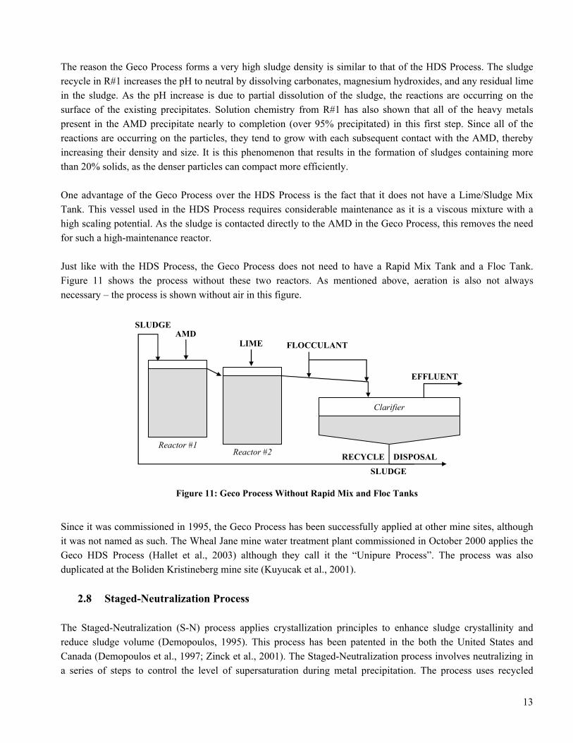
The reason the Geco Process forms a very high sludge density is similar to that of the HDS Process. The sludge recycle in R#1 increases the pH to neutral by dissolving carbonates, magnesium hydroxides, and any residual lime in the sludge. As the pH increase is due to partial dissolution of the sludge, the reactions are occurring on the surface of the existing precipitates. Solution chemistry from R#1 has also shown that all of the heavy metals present in the AMD precipitate nearly to completion (over 95% precipitated) in this first step. Since all of the reactions are occurring on the particles, they tend to grow with each subsequent contact with the AMD, thereby increasing their density and size. It is this phenomenon that results in the formation of sludges containing more than 20% solids, as the denser particles can compact more efficiently. One advantage of the Geco Process over the HDS Process is the fact that it does not have a Lime/Sludge Mix Tank. This vessel used in the HDS Process requires considerable maintenance as it is a viscous mixture with a high scaling potential. As the sludge is contacted directly to the AMD in the Geco Process, this removes the need for such a high-maintenance reactor. Just like with the HDS Process, the Geco Process does not need to have a Rapid Mix Tank and a Floc Tank.
shows the process without these two reactors. As mentioned above, aeration is also not always necessary – the process is shown without air in this figure. Figure 11
Figure 11: Geco Process Without Rapid Mix and Floc Tanks
AMD
EFFLUENT
SLUDGE
DISPOSALRECYCLE
SLUDGE
Reactor #1Reactor #2
Clarifier
FLOCCULANTLIME
Since it was commissioned in 1995, the Geco Process has been successfully applied at other mine sites, although it was not named as such. The Wheal Jane mine water treatment plant commissioned in October 2000 applies the Geco HDS Process (Hallet et al., 2003) although they call it the “Unipure Process”. The process was also duplicated at the Boliden Kristineberg mine site (Kuyucak et al., 2001).
2.8 Staged-Neutralization Process The Staged-Neutralization (S-N) process applies crystallization principles to enhance sludge crystallinity and reduce sludge volume (Demopoulos, 1995). This process has been patented in the both the United States and Canada (Demopoulos et al., 1997; Zinck et al., 2001). The Staged-Neutralization process involves neutralizing in a series of steps to control the level of supersaturation during metal precipitation. The process uses recycled
13

sludge in the first two reactors to partially neutralise the AMD. The sludge addition rate should be controlled to reach a desired pH, as illustrated in Figure 12. In the third and fourth reactors, lime is used to bring the slurry to the desired pH. A flocculant is then added to agglomerate the precipitates and enhance settling. The process design for Staged-Neutralization is solution specific. The number of reactors required and the target pH in each reactor is based on the metal type and concentration in the mine water to be treated as well as the degree of sludge density desired. This process has yet to be applied in the full scale. Although excellent sludge properties and low lime consumption would be expected, the capital costs would be higher than other processes as four full-size reactors are typically needed to properly apply the S-N Process.
AMD
LIME
EFFLUENT
SLUDGEDISPOSALRECYCLE
SLUDGE
R1 - pH 4.5 FlocTank
Clarifier
FLOCCULANT
R2 - pH 6.9 R3 - pH 8.2R4 - pH 9.5
AIR AIR
Figure 12: Staged-Neutralisation Process
3.0 Comparisons Between Processes In order to compare the treatment processes, pilot trials have been completed. Two pilot campaigns are summarised here: one completed by Noranda Inc. Technology Centre at Heath Steele Division and one completed by CANMET using their pilot plant facilities. The results and conclusions from these tests are summarised in the following sections.
3.1 Heath Steele Pilot Tests Pilot tests were completed in 1996 to compare the HDS Process with the Geco Process (Aubé, 2004a; Aubé and Payant, 1997). The sludge density (about 25% solids) and viscosity (about 40 cP) was similar for both processes. For effluent quality, there was a slight edge to the Geco Process. The Geco Process was also found to use less lime for neutralisation. The sludge stability was determined using leach tests, and these showed a slight advantage to the HDS process. A detailed analysis of results showed that the Geco process uses residual lime, magnesium hydroxide, and particularly calcium carbonate formed in the process to partially neutralise the AMD in the first reactor. Some of the calcium carbonate and Mg is re-precipitated in the second reactor, but the total remaining alkalinity in the
14

sludge is lower than that of the HDS Process. This means that the Geco Process would produce a less alkaline sludge, but it also means that it consumes less lime. This therefore represents the foremost trade-off between the Geco Process and the HDS Process: the Geco Process uses less lime but the HDS Process produces sludge with a higher neutralising capacity. The decision between the two processes therefore lies in the needs of the site. If the AMD contains mostly Fe and lower concentrations of Zn, Ni, and Cd, the sludge stability will not be significantly affected and the less-expensive Geco Process should be chosen. If the sludge contains some of these more soluble heavy metals and must be stored in a sensitive area, the HDS Process can be applied. If sludge stability is an important issue, lime can be added to the sludge as it is pumped to the storage area. This practise has been applied for years at Teck Cominco’s Kimberley Site, where the HDS Process has been operational since 1979 (Kuit, 1980). Either process can therefore be applied in this situation as the overall lime consumption will essentially be the same for a given sludge stability.
3.2 CANMET Pilot Tests In another pilot study, the HDS process, the Geco HDS process, and the Staged Neutralization process were compared in terms of treatment efficiency, costs, and environmental performance (Zinck and Griffith 2000). While all the HDS processes effectively treated the low-strength Fe-Zn rich acidic drainage solutions, there were subtle differences in their performance. For example, the Staged-Neutralization process produced the densest sludge followed by the Geco Process. As a disadvantage, the viscosity of the S-N was much higher than either the HDS or the Geco sludge. The settling rate for both the Geco and the S-N process sludges were faster than the HDS process sludge. Lime consumption was lowest with the S-N process followed by Geco and HDS process. This is expected as the AMD is neutralised in a single large step for the HDS Process, while the Geco Process uses two steps and the S-N process applied four. The step-wise neutralisation will effectively utilise any residual alkalinity in the sludge and improve lime efficiency by controlling the level of supersaturation in each reactor. 4.0 Scaling Issues
4.1 Gypsum A common by-product of lime neutralisation is gypsum. Gypsum precipitation occurs as the AMD is often rich is sulphate and the calcium added from lime will bring the solubility product well above saturation. This reaction is often responsible for scaling in treatment processes as well as increasing sludge production at sites where the feed sulphate concentrations can surpass 2500 mg/L.
Ca(OH)2 + H2SO4 ⇒ CaSO4.2H2O
This scale formation is particularly troublesome for plants where lime is added directly to a raw water that contains significant concentrations of sulphate. An HDS treatment system (including the Geco Process or Staged
15

Neutralisation) minimises scaling in reactors as the gypsum has other surfaces on which to precipitate. Gypsum is a crystal that preferentially forms on existing gypsum. When sludge is recycled, there are plenty of gypsum needles available in the slurry and these serve as preferred gypsum formation sites. If a plant operates without a recycle and significant sulphate is present, some precipitation will occur on the reactor wall surfaces. Once these surfaces are coated, gypsum precipitation is facilitated and the rate of precipitation increases. HDS processes are therefore preferred for high sulphate effluents as they will minimise scaling in the reactors. But the reactors aren’t the only potential problem, as discussed in the next paragraph. One reason why gypsum can be so problematic is because this solid forms very slowly. While hydroxide reactions that cause the precipitation of metals are almost instantaneous, gypsum formation can take days to reach equilibrium. This is why effluent systems are often covered in gypsum scale, even in HDS plants: the precipitation process does not have time to come to completion within the process, so the effluent is still supersaturated for gypsum and precipitation continues. In most AMD treatment plants, the final effluent is supersaturated for gypsum. Fortunately, this is generally only a slight supersaturation and a small dilution once released will prevent scale formation in the receiving streams or lakes. Often it is the clarifier overflow weir, effluent piping, flume, turbidimeters, and pH probes that sustain the greatest amount of scaling. Preventing gypsum scaling in the effluent system is generally not cost-effective. This precipitate is not pH sensitive, which means it can be precipitated in alkaline, neutral, or acidic conditions. It is also a very hard scale which can be difficult to remove from solid surfaces. Once the scale has achieved a certain thickness, it can be cheaper to replace scaled-up effluent piping rather than try to clean it. Pigs can be used to maintain piping if done regularly. This is generally the least expensive method of controlling gypsum scale formation. Another method is to coat the surfaces prior to subjecting them to scale. For example, it is possible to coat clarifier walls with grease to allow for easy removal at yearly shutdowns. A rubber liner can also be used to facilitate scale removal. Anti-scaling agents are not recommended for lime treatment plants. These are expensive and typically only reduce scaling without eliminating it. These can also interfere with the treatment efficiency as metal removal is also a precipitation process. Another potential issue is toxicity of the final effluent as the anti-scalant is released at the end of the process.
4.2 Calcite Another common by-product of lime neutralisation is calcium carbonate. The inorganic carbon for this reaction can either come from the AMD itself or be a result of carbon dioxide from air, which is dissolved during aeration. This carbon dioxide converts to bicarbonate and then partially to carbonate due to the high pH (see Figure 13). The carbonate fraction will precipitate with the high calcium content of the slurry to form calcite (calcium carbonate). This calcite can play an important role in the stability of the final sludge product as it provides neutralising potential to the sludge as it is stored. It is also an indicator of the process lime efficiency: more efficient neutralising processes will produce less calcite.
Ca2+ + CO32- ⇒ CaCO3
16

Figure 13: Inorganic Carbon Equilibrium
(from: http://www.bio.psu.edu/courses/fall2002/biol435/Class_Notes/4)
As illustrated in Figure 13, the carbonate species (CO3
2-) is only prevalent at pH values of more than about 10.3 and is practically non-existent at pH values of less than 8.5. As it is only this species that precipitates with calcium to form calcite, the formation of calcite at pH values of less than 8.5 is rare. For calcite precipitation to occur at neutral pH values, the total inorganic carbon concentrations would need to be very high. 5.0 Arsenic Treatment Treating arsenic (As) just with lime requires a very high pH and forms an unstable sludge consisting primarily of calcium arsenate. A more acceptable treatment is co-precipitation of arsenic with ferric and/or base metals such as copper and zinc. In all cases, oxidation of As(III) to As(V) may be required both for improved treatment efficiency and the production of a stable sludge. Many oxidants can be used with varying effectiveness and cost. When treating with ferric iron, it is preferable to have a two-step process which precipitates most of the As at a slightly acidic pH (4 to 6). This will form a more stable precipitate (ferric arsenate). In the second step, any other heavy metals present are precipitated and the remaining arsenic is essentially removed from solution. When using a clarifier for solid/liquid separation, a sludge recycle can be used to increase treatment efficiency. This can result in significant savings in reagent addition but can also cause the arsenic to be mostly adsorbed as opposed to co-precipitated. Adsorbed arsenic is slightly less stable than when it is co-precipitated as a ferric arsenate. The recycle will also help improve lime efficiency. An excess of iron can be applied with any process to improve sludge stability. The final sludge disposal system can weigh into the decision as to whether a recycle is applied and what ratio of iron to arsenic is used.
17

6.0 Molybdenum Treatment Molybdenum is typically present as an anion in neutral-pH waters (HMoO4
-) and does not precipitate with lime addition as do the typical heavy metals (Figure 1). The most widely-applied treatment process for mine drainages containing Mo is ferric co-precipitation. An example is given in for the Noranda Inc., Brenda Mines treatment plant (Aubé and Stroiazzo, 2000). Here, ferric sulphate is added to the alkaline mine drainage in the first step, and the pH is controlled to 4.5 in the second step. A flocculant is added to improve solid/liquid separation in the clarifier. Due to their very low discharge limit, a sand filter is also used to remove all residual Mo from the effluent. This plant treats a mine drainage with about 3 mg/L of Mo to a final discharge of 0.03 mg/L.
Figure 14
Figure 14: Brenda Molybdenum Treatment Process (from Aubé and Stroiazzo, 2000)
Ferric
Sulphate
PolishingPond
Sludge
DisposalRecycle
Reactor 1Reactor 2
Reactor Clarifier
FlocculantRaw Water
SulphuricAcid
Sand Filter
Alkali
NeutralisationTank
pH 4.5pH ~8
FerricSulphate
PolishingPond
Sludge
DisposalRecycle
Reactor 1Reactor 2
Reactor Clarifier
FlocculantRaw Water
SulphuricAcid
Sand Filter
Alkali
NeutralisationTank
pH 4.5pH ~8
For many sites, it is not necessary to have this many steps to the process. It is possible to attain a Mo concentration of less then 0.3 mg/L without sand filtration and the pH control can be completed in the same reactor as the iron addition. In fact, pH control sometimes requires an alkali instead of an acid as ferric sulphate addition depresses pH significantly. At Brenda Mines, sulphuric acid is required because the mine drainage contains significant alkalinity. 7.0 Sludge Disposal There are many different disposal scenarios used throughout the industry, ranging from off-site transport to disposal in mine workings (Aubé, 2004b). The choice depends on many factors including regulatory considerations, sludge stability, sludge production rate, space availability, budget, and aesthetic considerations. On some particularly sensitive sites, regulators do not allow on-site storage. These sites will normally choose a high-density sludge process and further densify the sludge prior to transport. The most common means of densification is the use of filter presses (plate and frame). This is the most expensive option, particularly if it is necessary to pay a third party for disposal.
18

Disposal in mine workings is often the least expensive option and is recently acquiring more public and regulatory approval. Often considered a bad option for long-term environmental impact, some tests have shown that the impact may in fact be positive. At Cape Breton Development Corporation (CBDC) for example, disposal of treatment sludge into decommissioned underground coal mines has shown to have a positive impact on the mine water (Aubé, 2004b). This sludge consists primarily of iron hydroxides and gypsum with a significant fraction of magnesium hydroxides. Since the underground waters are already in equilibrium with the iron system, the ferric hydroxides do not dissolve. Gypsum is also saturated in the mine and does not dissolve. Some of the magnesium will dissolve and increase pH. This pH increase will precipitate a small fraction of the ferric iron in solution in the mine workings. Returning sludge underground at CBDC therefore improves the mine water quality and does not appear to cause long-term stability issues. Other options for disposal of lime treatment sludge includes disposal with tailings, in engineered ponds, on waste rock piles, under a water cover, or in natural land depressions. Disposal with tailings can be done for operating mines and would have the same advantages and disadvantages as in-line treatment and co-deposition (see section 2.3). Another option is to dispose of sludge over top of a closed tailings pile. Covering tailings with sludge may help reduce oxidation by providing a wet barrier similar to that of engineered soil covers. Unfortunately, these options have not yet been sufficiently researched to confirm that this sludge would not eventually re-dissolve if tailings oxidation continues. The engineered pond disposal is more expensive at first, but eventually results in the lowest volume of sludge generated. This is because these ponds can be designed to both drain water from the bottom and allow for evaporation from the top. Most sludges will densify to two or three times their original solid content when disposed of in this way. Some operators allow their sludge to densify in an engineered pond for a year or two before transporting it to a different location (on tailings or in mine workings). Sludge stored underwater will not densify as much as surface disposed sludge, but this option is viable as the sludge remains stable in this environment (Zinck, 2004). For surface disposal options, revegetation is important to minimise dusting and improve aesthetics. It is possible to revegetate sludge directly, but it can more easily be done with a layer of topsoil. Sludge revegetation is the subject of on-going studies at CANMET (Zinck, 2004). 8.0 Cost Effectiveness of Treatment There are many operational methods which can be improved upon to reduce costs without compromising treatment efficiency. In fact, a detailed plant optimisation will often improve both cost and performance simultaneously. Major cost opportunities are often found in the proper calibration and maintenance of instruments. Turbidimeters, pH probes, level detectors, density-meters, and flowmeters can all affect different parts of the process and increase costs significantly. The automation and PID controls of pH and flows must be re-calibrated periodically to maintain performance and prevent oscillations. At times, lime slaking can be optimised with simple modification of control parameters. An in-depth review of a treatment plant and the cost distribution can bring up items that are disproportionately expensive in comparison to other plants. This can point to faulty equipment requiring excessive maintenance but
19

is more often related to operating practices. If it is related to faulty equipment, this equipment should be replaced or repaired. If it is related to bad operating practices, re-training of operators may be required. One example of an expensive operating practice is to recycle treated water to the raw water pond whenever upsets occur. During a plant start-up, this practice may be necessary to define the proper operating parameters required to bring the effluent to within discharge objectives. But operators may then understand this to be the normal operating method for any plant upset. In effect, water is treated to within 90% of release requirements, then returned to the raw water pond to be treated again. The cost of treating this water is therefore double the normal cost (in $/m3). It is usually better to stop the treatment plant when process upsets occur, correct the problem, then re-start the plant. 9.0 Conclusion There is no shortage of selection when it comes to choosing an active treatment method for mine water or smelter effluents. As discussed in this document, each process has particular advantages and disadvantages. The appropriate choice is site-dependent and should be based on the specific treatment challenges. For example, if sludge disposal volume is an important concern, than the HDS Process or Geco Process should be selected. For improved lime efficiency, the Geco or Staged-Neutralization process should be considered. If capital investment is a concern and a large surface area is available, then perhaps pond treatment would be an effective treatment option. In special cases where an unused open pit is available, pit treatment may be the least expensive option. Options are more limited when treatment for arsenic or molybdenum is required, but there remain some site-specific issues that must be addressed for each location. 10.0 References Aubé, B., 2004a. “Une étude en usine pilote de la production de boues à haute densité durant le traitement des eaux de drainage minier acide” {English Title: “A Pilot Study of High Density Sludge Production in Acid Mine Drainage Treatment”} Master’s thesis submitted to Université de Montréal – École polytechnique. April, 2004. Aubé, B., 2004b. “Sludge Disposal in Mine Workings at Cape Breton Development Corporation” Presented at Sludge Management and Treatment of Weak Acid or Neutral pH Drainage. In: Proceedings of the 2004 Ontario MEND Workshop, MEND report W.017, Sudbury Ontario, May 26-27, 2004. Aubé, B. 2004c. "Successful Use of Design of Experiment to Improve Treatment of Zn in a Pond System" Presented at the Ontario Mining Association Mines Rehabilitation Field Conference. Thunder Bay, Ontario, September 13-16, 2004. Aubé, B., and Arseneault, B. 2003. “In-Pit Mine Drainage Treatment System in a Northern Climate” In Proceedings for “Sudbury 2003 Mining and the Environment Conference”, May 25-28 2003. (available at http://www.enviraube.com/images/raglan.pdf) Aubé, B., and J. Stroiazzo, 2000. “Molybdenum Treatment at Brenda Mines”. Proceedings of the 5th International Conference on Acid Rock Drainage, 2000.
20

21
Aubé, B. 1999. "Innovative Modification to High Density Sludge Process" Proceedings for Sudbury ’99, Mining and the Environment II. Aubé B. and J.M. Zinck, 1999. "Comparison of AMD Treatment Processes and their Impact on Sludge Characteristics". Proceedings for Sudbury ’99, Mining and the Environment II. Aubé, B.C., and Payant, S.C., 1997. "The Geco Process: A New High Density Sludge Treatment for Acid Mine Drainage" Proceedings of the Fourth International Conference on Acid Rock Drainage. Demopoulos, G.P., Zinck, J.M. and Kondos, P.D., 1995. Production of Super Dense Sludges with a Novel Neutralization Method, In: Waste Processing and Recycling in Mineral and Metallurgical Industries II. (Eds. S.R. Rao, L.M. Amaratunga, G.G. Richards and P.D. Kondos), Vancouver, B.C. Aug. 20-24, 1995. pp 401-411.
Demopoulos, G.P., Zinck, J.M. and Kondos, P.D., 1997. Multiple Stage Precipitation of Heavy Metals from Acidic Aqueous Solutions., U.S. Patent # 5,672,280. September 30, 1997 Hallett, Clive, R. Coulton, C. Marsden, 2003. “A Clear Success” In: Mining Environmental Management, May 2003, pp. 10-12. Kuit, W.J., 1980. “Mine and Tailings Effluent Treatment at the Kimberley, B.C. Operations of Cominco Ltd”, CIM Bulletin, Dec. 1980, pp. 105-112. Kuyucak, N., M. Lindvall, T. Sundqvist and H. Sturk., 2001. “Implementation of a High Density Sludge “HDS” Treatment Process at the Kristineberg Mine Site”. Securing the Future 2001, Mining and the Environment Conference proceedings. June 2001. Villachica, C., M.R. Carlo, C.E. Dextre, and D. Valdizan "Dynamic Neutralization and Coagulation (DNC) Process for Efficient and Low Cost Treatment of Acid Mine Drainage" Zinck, J.M., 2004. “Lime Sludge Management – An Update on Technologies” Presented at Sludge Management and Treatment of Weak Acid or Neutral pH Drainage. In: Proceedings of the 2004 Ontario MEND Workshop, MEND report W.017, Sudbury Ontario, May 26-27, 2004. Zinck, J.M. and Aubé, B.C. 1999. "Optimization of Lime Treatment Processes". Proceedings of the 31st Annual Canadian Mineral Processors Conference. Zinck, J.M. and W.F. Griffith, 2000. “An Assessment of HDS-Type Lime Treatment Processes-Efficiency and Environmental Impact” In: 5th International Conference on Acid Rock Drainage, Denver, Colorado, May 21-24, 2000 Zinck, J.M., Demopoulos, G.P. and Kondos, P.D. , 2001. “Improved precipitation process for acidic mineral effluent treatment”, Canadian patent # 2,149,493. March 20, 2001.