lightpointe - airelink 60 installation and user manual · airelink 60 installation and user manual...
TRANSCRIPT

LightPointe - AireLink 60 Installation and User Manual
AireLink 60 Installation and User Manual Rev. C
Page ii
COPYRIGHTS AND DISCLAIMER
2015, LightPointe. All Rights Reserved
Information in this document is provided in connection with LightPointe products. These
materials are provided by LightPointe as a service to its customers and may be used for
information purposes only. LightPointe assumes no responsibility for errors or omissions in
these materials. LightPointe may make changes to specifications and product descriptions at
any time, without notice. LightPointe makes no commitment to update the information and
shall have no responsibility whatsoever for conflicts or incompatibilities arising from future
changes to its specifications and product descriptions.
No license, express or implied, by estoppel or otherwise, to any intellectual property rights is
granted by this document. Except as provided in LightPointe Terms and Conditions of Sale for
such products, LightPointe assumes no liability whatsoever.
These materials are provided “as is” without warranty of any kind, either expressed or implied,
relating to sale and/or use of LightPointe products including liability or warranties relating to
fitness for a particular purpose, consequential or incidental damages, merchantability, or
infringement of any patent copyright or other intellectual property right. LightPointe further
does not warrant the accuracy or completeness of the information, text, graphics or other
items contained within these materials. LightPointe shall not be liable for any special, indirect,
incidental, or consequential damages, including without limitation, lost revenues or lost
profits, which may result from the use of these materials.
The Bluetooth application provided with the system includes software code developed
partially under an MIT open software license agreement.
LightPointe products are not intended for use in medical, lifesaving or life sustaining
applications. LightPointe customers using or selling LightPointe products for use in such
applications do so at their own risk and agree to fully indemnify LightPointe for any damages
resulting from such improper use or sale.
The following are trademarks of LightPointe Product names or services listed in this publication
are for identification purposes only, and may be trademarks of third parties. Third-party
brands and names are the property of their respective owners.
FligħtLite, FligħtStrata, FligħtManager, AireLite, AireLink™, AireStrata, AireForce,
DualPath™, AireManager and Airelink are trademarks of LightPointe.
LightPointe believes the printed matter contained herein to be accurate from date of
publication and reserves the right to make changes as necessary without notice.
AireLink 60 Installation and User Manual Rev. C
Page iii
Reader Response: LightPointe strives to produce quality documentation and welcomes your
feedback. Please send comments and suggestions to LightPointe. For technical questions,
contact your local LightPointe sales office or field applications engineer.
AireLink 60 Installation and User Manual Rev. D Introduction
Page 4
TABLE OF CONTENTS
1 Introduction 18
1.1 Shipping Content 18
1.1.1 AireLink™ 60 with integrated antenna 18 1.1.2 AireLink™ 60 with external antenna: 20
1.2 Main Radio Components 21
1.2.1 AireLink™ 60 ODU with integrated antennas 21 1.2.2 AireLink™ 60 ODU with external antennas 22 1.2.3 External Antennas and Mounting Brackets 23 1.2.4 Power over Ethernet (PoE) Modules 24 1.2.5 Miscellaneous 25
1.2.5.1 RSSI Alignment Cables 25
1.2.5.2 Lightning/ Surge Protection 25
1.2.5.3 Optional: Ethernet Cable Extender 26
1.2.5.4 Optional: Antenna Alignment Tool 26
1.2.5.5 Optional: Weather shield for SX model 27
2 Surveying the Installation Site 29
2.1 Tools 29
2.2 Installation Site Review 29
2.3 Link Distance 31
2.4 Antenna Location 32
2.5 Atmospheric and Rain Attenuation of Millimeter Wave Beams 32
3 Networking, Power and Service Connections 41
3.1 AireLink™ 60 User Panel 41
3.2 Power Connection 44
3.2.1 Powering via PoE 44 3.2.2 Powering via Direct 48 Vdc 45
3.3 Grounding/ Lightning protection 46
3.4 Network Data Connection 48
3.5 Out-Of-Band Management Connection 49
3.6 Console Port 49
3.7 RSSI Voltage Connector 49
3.8 Bluetooth Antenna Connector 50
4 Recommended Software Pre-Configurations 52
4.1 Required Network Settings Info 52
4.2 Airelink Configuration via TELNET CLI INTERFACE 52
AireLink 60 Installation and User Manual Rev. D Introduction
Page 5
5 System Installation 57
5.1 Tools 57
5.2 Universal Mount Assembly 58
5.3 Pole Mount Installation of Airelink 60 with Integrated Antenna 59
5.4 Pole Mount Installation of Airelink 60 with External Antenna 60
5.5 ODU Installation (External Antenna System only) 61
5.6 System Alignment Basics 62
5.7 Antenna Radiation Pattern and Side Lobes 63
5.8 Installing Airelink™ 60 with Integrated 12 cm Antenna 64
5.9 Installing Airelink™ 60 with External Antennas 70
5.10 Installing the Optional Alignment Sight Tool for External Antennas 70
5.11 Airelink™ 60 with 1 Foot Antenna 70
5.12 Airelink™ 60 with 2 Foot Antenna 72
5.13 Configuration of the Alignment Sight Tool 72
5.14 Mounting Bracket Adjustment 73
5.15 Aligning the 60 Ghz Antennas 75
6 LinkManager™– Network Management Platform 82
6.1 Management Application Views 82
6.2 System View 84
6.3 RF LINK VIEW 85
6.4 PORT STATUS View 86
6.5 Management View 89
6.6 PERFORMANCE View 90
6.7 STATISTICS View 91
6.8 SNMP View 92
6.9 SOFTWARE View 93
6.10 ADMINISTRATION 94
7 CLI -- Command Line Interface 95
7.1 User Mode Commands 96
7.2 CLI – SHOW Command 96
7.2.1 Command Show Flash 97 7.2.2 Command Show Interface 97 7.2.3 Command Show Performance 98 7.2.4 Command Show Radio 98 7.2.5 Command Show SNMP 99 7.2.6 Command Show System 99
AireLink 60 Installation and User Manual Rev. D Introduction
Page 6
7.2.7 Command Show Versions 100 7.2.8 Command Show VLAN 100
7.3 CLI --Configuration Commands 100
7.3.1 Interface Commands 101
7.3.1.1 Interface data commands 101
7.3.1.2 Interface management commands 102
7.3.2 Password Command 104 7.3.3 Performance Commands 104 7.3.4 Radio Commands 105 7.3.5 SNMP Commands 107 7.3.6 System Commands 108 7.3.7 Reboot Command 109 7.3.8 Exit Command 109
7.4 CLI -- Save Session Settings on Flash and sOFTWARE Upgrade 109
7.5 CLI -- PING Command 110
7.6 CLI – Upgrade TFTP Command 110
7.7 CLI – LOG Command 110
8 Bluetooth AireLink Viewer 113
9 SNMP 117
9.1 Basics 117
9.2 LightPointe MIB Files 117
9.3 LightPointe MIB Tree 118
9.4 SNMP Trap Monitoring 120
10 Troubleshooting and Diagnostics 122
10.1 Failure Types 122
11 Advanced Troubleshooting Methods 126
11.1 Performing a PING Test 126
11.2 Equipment Connection and Network Settings 126
11.3 Step-by-Step Instructions to Perform a PING Test 127
11.4 BER Testing 128
12 Specifications 130
13 Technical Support 131
13.1 Return Material Authorization (RMA) Procedure 132
13.2 Contacting LightPointe 132
AireLink 60 Installation and User Manual Rev. D Introduction
Page 7
LIST OF FIGURES
Figure 1-1: AireLink™ 60 with integrated antenna (left) and accessories (next page) .................. 19
Figure 1-2: Shipping Box 1 (AireLink™ 60 detachable ODU and accessories) .............................. 20
Figure 1-3: Shipping Boxes 2 and 3 (1 foot antennas) ............................................................ 20
Figure 1-4: Shipping Boxes 2 and 3 (2 foot antennas) ............................................................. 21
Figure 1-5: AireLink™ 60 with integrated antenna and view of access panel cover ....................... 22
Figure 1-6: AireLink™ 60 ODU ............................................................................................. 22
Figure 1-7: AireLink™60 with one foot (top) and two foot (bottom) antennas attached. ............... 23
Figure 1-8: Alignment bracket and locations of alignment screws .............................................. 23
Figure 1-9: Power over Ethernet modules ............................................................................... 24
Figure 1-10: Optional dc power supply ................................................................................... 24
Figure 1-11: RSSI alignment cables ....................................................................................... 25
Figure 1-12: Surge Protectors ............................................................................................... 26
Figure 1-13: Ethernet Cable Length Extender ......................................................................... 26
Figure 1-14: Alignment Tool for integrated (left) and external Antenna (right) ............................ 27
Figure 1-15: Side and front view of AireLink 60-SX with optional weather shield installed. ............ 27
Figure 2-1: Fresnel Zone illustration. ..................................................................................... 30
Figure 2-2: Atmospheric attenuation of signals at different frequencies. ..................................... 32
Figure 2-3: ITU rain zone chart of the earth ........................................................................... 33
Figure 2-4: AireLink™ 60 Distance vs. Availability North America .............................................. 35
Figure 2-5: AireLink™ 60 Distance vs. Availability Europe........................................................ 37
Figure 2-6: AireLink™ 60 Distance vs. Availability Australia ..................................................... 38
Figure 2-4: Typical AireLink™ 60 RSSI vs. Distance chart ......................................................... 39
Figure 3-1: AireLink™ 60 User Panel with plastic cover removed ............................................... 42
Figure 3-2: AireLink™ 60 User panel ...................................................................................... 42
Figure 3-3: Powering via PoE ................................................................................................ 44
Figure 3-4: Direct 48 Vdc Power Connection ........................................................................... 46
Figure 3-5: Enclosure Ground Connection ............................................................................... 46
Figure 3-7: Lightning Protection Zones .................................................................................. 47
Figure 3-8: Data Network Connection .................................................................................... 48
Figure 3-9: RSSI Voltage Port Connector Location ................................................................... 49
Figure 3-10: Bluetooth antenna connection ............................................................................ 50
Figure 5-1: Assembled Universal Mount and Base Plate Hole Pattern ......................................... 58
Figure 5-2: ODU Polarization Directions ................................................................................. 61
Figure 5-3: AireLink™ 60 installed on LightPointe Universal Mount ............................................ 62
Figure 5-4: Typical antenna Radiation Pattern Envelope (RPE) diagram ...................................... 63
Figure 5-5: Alignment Sight Tool (Integrated Antenna System) ................................................ 65
AireLink 60 Installation and User Manual Rev. D Introduction
Page 8
Figure 5-6: Antenna alignment scan ...................................................................................... 66
Figure 5-7: Simple illustration of the alignment process ........................................................... 67
Figure 5-8: Typical AireLink 60-SX RSSI vs. Distance Charts for standard distance setting ......... 68
Figure 5-9: Default User Panel status after successful alignment ............................................... 69
Figure 5-10: Alignment Sight Tool (External Antenna System) .................................................. 70
Figure 5-11: Attach Alignment Sight Tool to external 1 foot antenna ......................................... 71
Figure 5-12: Attach Alignment Sight Tool to external 2 foot antenna ......................................... 72
Figure 5-13: Re-configuring Alignment Sight Tool.................................................................... 72
Figure 5-14: Elevation Adjustment ........................................................................................ 73
Figure 5-15: Azimuth Adjustment .......................................................................................... 74
Figure 5-16: Antenna alignment scan .................................................................................... 77
Figure 5-17: Simple illustration of the alignment process ......................................................... 78
Figure 5-18: Typical AireLink 60 MX/LX RSSI vs. Distance Charts for stand distance settings ........ 79
Figure 5-19: Default User Panel status after successful alignment ............................................. 79
Figure 6-1: LinkManager™ Login Window .............................................................................. 82
Figure 6-2: LinkManager Registration Screen ......................................................................... 82
Figure 6-3: LinkManager™ Main Screen ................................................................................ 83
Figure 6-4: System View Screen .......................................................................................... 84
Figure 6-5: RF Link View Screen........................................................................................... 85
Figure 6-6: Port Status View (RJ45 Data Port) ....................................................................... 86
Figure 6-7: Port Status View (SFP Data Port) ......................................................................... 87
Figure 6-8: Port Status View (RJ45 Management Port) ............................................................ 88
Figure 6-9: Management View Screen ................................................................................... 89
Figure 6-10: Performance View Screen ................................................................................. 90
Figure 6-11: Statistics View Screen ...................................................................................... 91
Figure 6-12: SNMP View Screen ........................................................................................... 92
Figure 6-13: Software View Screen ...................................................................................... 93
Figure 6-14: Administration View Screen ............................................................................... 94
Figure 9-1: LightPointe MIB modules ................................................................................... 117
Figure 9-2: MIB tree iso/org/dod/internet/private/enterprises/lpcomm .................................... 118
Figure 9-3: Detailed view of LPCOMM MIB tree ..................................................................... 119
Figure 9-4: Performance Graph ........................................................................................... 120
Figure 9-5: SNMP Traps ..................................................................................................... 120
AireLink 60 Installation and User Manual Rev. D Introduction
Page 9
LIST OF TABLES
Table 2-1 Fresnel zone path clearan .................................................................................... 30
Table 2-2: Rain rates, duration and 60 GHz signal attenuation ............................................... 34
Table 3-1: User Panel Connections and Status LEDs .............................................................. 43
Table 9-1: Troubleshooting Chart I ................................................................................... 123
Table 9-2: Troubleshooting Chart II .................................................................................. 124
AireLink 60 Installation and User Manual Rev. D Introduction
Page 10
INFORMATION TO USER
NOTE: CHANGES OR MODIFICATIONS OF THE SYSTEM NOT EXPRESSLY APPROVED BY
LIGHTPOINTE COULD VOID THE USER'S AUTHORITY TO OPERATE THE EQUIPMENT.
Cautions and Warnings
The following symbols are used in this manual to indicate that the installer should take particular
caution to prevent injury or damage to the equipment.
Exercise caution when you see this symbol. It indicates actions that
could be harmful to the installer or to the equipment.
Prenez garde lorsque vous voyez ce symbole, il s'agit d'un
avertissement indiquant qu'il y a danger pour l'installateur ou
l'equipement.
Exercise extreme caution when you see this symbol. It indicates
potentially lethal voltages!
Soyez extremement prudent lorsque vous voyez ce symbole, il
s'agit d'un avertissement denotant la presence de haut voltage
pouvant causer la mort ou des blessures graves.
Note: There are no serviceable parts within the units and the system should not be opened in the
field.
Observe Standard Precautions
All persons having access to this equipment must observe all standard precautions as defined in
applicable national statutory health and safety legislation.
The outdoor equipment must be properly protected against voltage surges and prevent the built-up of
static electric charges. We recommend following the IEC 61024/ IEC 62305 standards for proper
lightning protection.
For installations in the U.S.A., for information with respect to proper grounding and applicable lightning
protection for DC cables please refer to Articles 810830 of the National Electrical Code, ANSI/NFPA No.
70.
In case the system is installed in a country outside of the U.S.A., implement protection in accordance
with local safety standards and regulatory requirements.
AireLink 60 Installation and User Manual Rev. D Introduction
Page 11
Do not install or operate this equipment in the presence of or close to flammable gases or fumes.
Operation of any electrical equipment in such an environment constitutes a potential safety hazard.
Qualified Personnel
Qualified personnel who understand and are trained to work with the equipment must perform all
repair, modification, reconfiguration, and upgrading operations.
Note: Always power the system down before moving or removing the system.
Service
There are no serviceable parts within the radio units. Only factory trained personnel can provide service
on any internal components of the radio units.
Export Control
All LightPointe AireLink™ radio products are commodities that fall under ECCN 5A002 of the
Department of Commerce. These products are "ENC restricted" under section 740.17(b)(1) of the
Export Administration Regulations (EAR). This License Exception ENC does not authorize export or re-
export to, or provision of any service in any country listed in Country Group E:1 in Supplement No. 1
to part 740 of the EAR. Diversion contrary to U.S. law is expressly prohibited.
Regulatory Information
North America:
These devices have been type approved by FCC in accordance with 47 CFR PART 15.255 of the Federal
Communication Commission rules and Industry Canada RSS-210 Issue 8.
No license is required in the U.S. or Canada for millimeter wave radio transmission equipment operating
in the 57-64 GHz frequency band. Customers in other countries are responsible for obtaining proper
operator licenses in case they are required by law.
47 CFR Part 15.255
This device complies with Part 15.255 of the FCC Rules. Operation is subject to the following conditions:
This device may not cause harmful interference, and
This device must accept any interference received, including interference that may cause undesired
operation.
AireLink 60 Installation and User Manual Rev. D Introduction
Page 12
Industry Canada RS210 Issue 8
This Class 1 digital apparatus complies with the Canadian RSS-210 regulation.
Cet appareil de la classe 1 est conforme à la norme RSS-210 du Canada.
European Union:
These devices are in compliance with the European Directive R&TTE 1999/5/EC on Radio Equipment
and Telecommunications Terminal Equipment and have been assessed against the following Applicable
Standards:
EN 302 217-3 V2.2.1 (2014-04)
R&TTE: EN 302 217-4-2 V1.5.1 (2010-01)
EN 301 489-1 V1.9.2 (2011-09)
EN 301-489-4 V2.2.0 (2015-01)
IEC/EN 60950-1:2005 (2nd Ed.), +A1: 2009, +A11:2009, +A12:2011
Environmental: This product is ROHS compliant
Other Recommendations and Selected National Standards
ECC/CEPT: ECC/REC/(09)01
Germany: SSB FE-OE 034 (Ausgabe 2/2012)
Notification number 2012/0245/D
Austria: FSB-RR072
Switzerland: RIR0302-47
Australia: Radcom LIPD LIC2000 Schedule 1, Item 51
AireLink 60 Installation and User Manual Rev. D Introduction
Page 13
UNDER THE EUROPEAN COMMISSION ONE-STOP-NOTIFICATION (OSN) PROCESS,
NOTIFICATION #11474, THE NATIONAL REGULATORY AUTHORITIES OF THE
FOLLOWING EUROPEAN MEMBER COUNTRIES HAVE BEEN NOTIFIED AND THE
EQUIPMENT MAY BE OPERATED IN THE FOLLOWING COUNTRIES:
AT BE BG CZ DK
EE FI FR DE GR
IS IE LV LT LU
MT NL NO PT RO
SK SI SE CH UK
RF Exposure evaluation
To ensure public safety requirements for installation of an RF system in an uncontrolled location, an
RF exposure calculation was performed by an independent and accredited test lab (NEMKO USA). The
results are presented below.
Safe distance according to FCC CFR 47 § 1.1307, §1.1310; and Industry Canada’s (IC) RSS-102, Issue 5, Safety Code 6
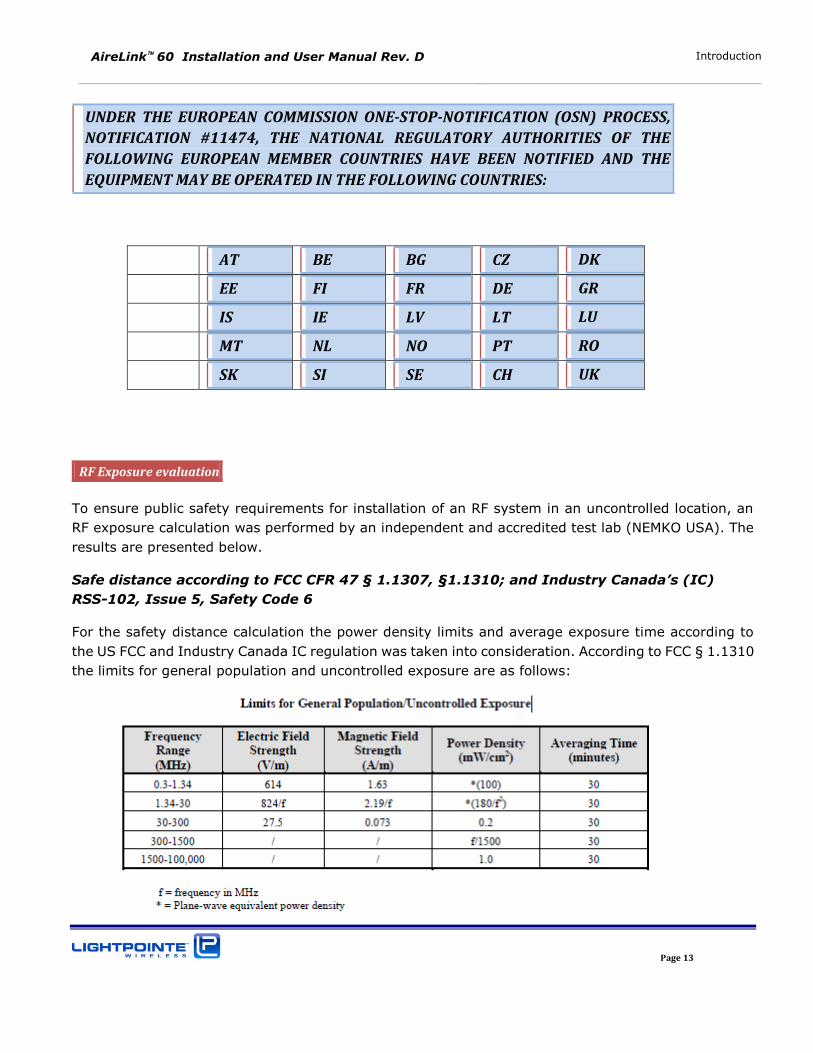
For the safety distance calculation the power density limits and average exposure time according to
the US FCC and Industry Canada IC regulation was taken into consideration. According to FCC § 1.1310
the limits for general population and uncontrolled exposure are as follows:
AireLink 60 Installation and User Manual Rev. D Introduction
Page 14
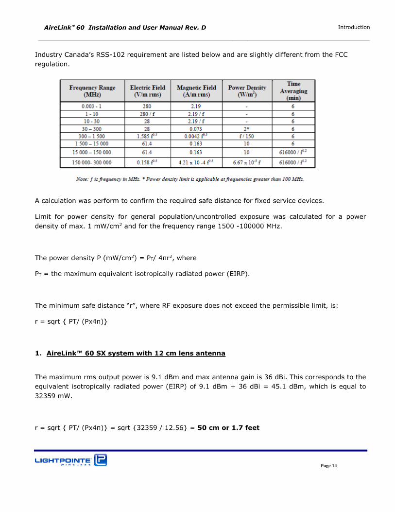
Industry Canada’s RSS-102 requirement are listed below and are slightly different from the FCC
regulation.
A calculation was perform to confirm the required safe distance for fixed service devices.
Limit for power density for general population/uncontrolled exposure was calculated for a power
density of max. 1 mW/cm2 and for the frequency range 1500 -100000 MHz.
The power density P (mW/cm2) = PT/ 4πr2, where
PT = the maximum equivalent isotropically radiated power (EIRP).
The minimum safe distance “r”, where RF exposure does not exceed the permissible limit, is:
r = sqrt { PT/ (Px4π)}
1. AireLink™ 60 SX system with 12 cm lens antenna
The maximum rms output power is 9.1 dBm and max antenna gain is 36 dBi. This corresponds to the
equivalent isotropically radiated power (EIRP) of 9.1 dBm + 36 dBi = 45.1 dBm, which is equal to
32359 mW.
r = sqrt { PT/ (Px4π)} = sqrt {32359 / 12.56} = 50 cm or 1.7 feet
AireLink 60 Installation and User Manual Rev. D Introduction
Page 15
2. AireLink™ 60 MX system with 30 cm parabolic antenna
The maximum rms output power is 9.1 dBm and max antenna gain is 42 dBi. This corresponds to the
equivalent isotropically radiated power (EIRP) of 9.1 dBm + 42 dBi = 51.1 dBm, which is equal to
128825 mW.
r = sqrt { PT/ (Px4π)} = sqrt {128825 / 12.56} = 100 cm or 3.3 feet
3. AireLink™ 60 LX system with 60 cm parabolic antenna
The maximum rms output power is 9.1 dBm and max antenna gain is 47 dBi. This corresponds to the
equivalent isotropically radiated power (EIRP) of 9.1 dBm + 47 dBi = 56.1 dBm, which is equal to
407380 mW.
r = sqrt { PT/ (Px4π)} = sqrt {407380 / 12.56} = 180 cm or 6.0 feet
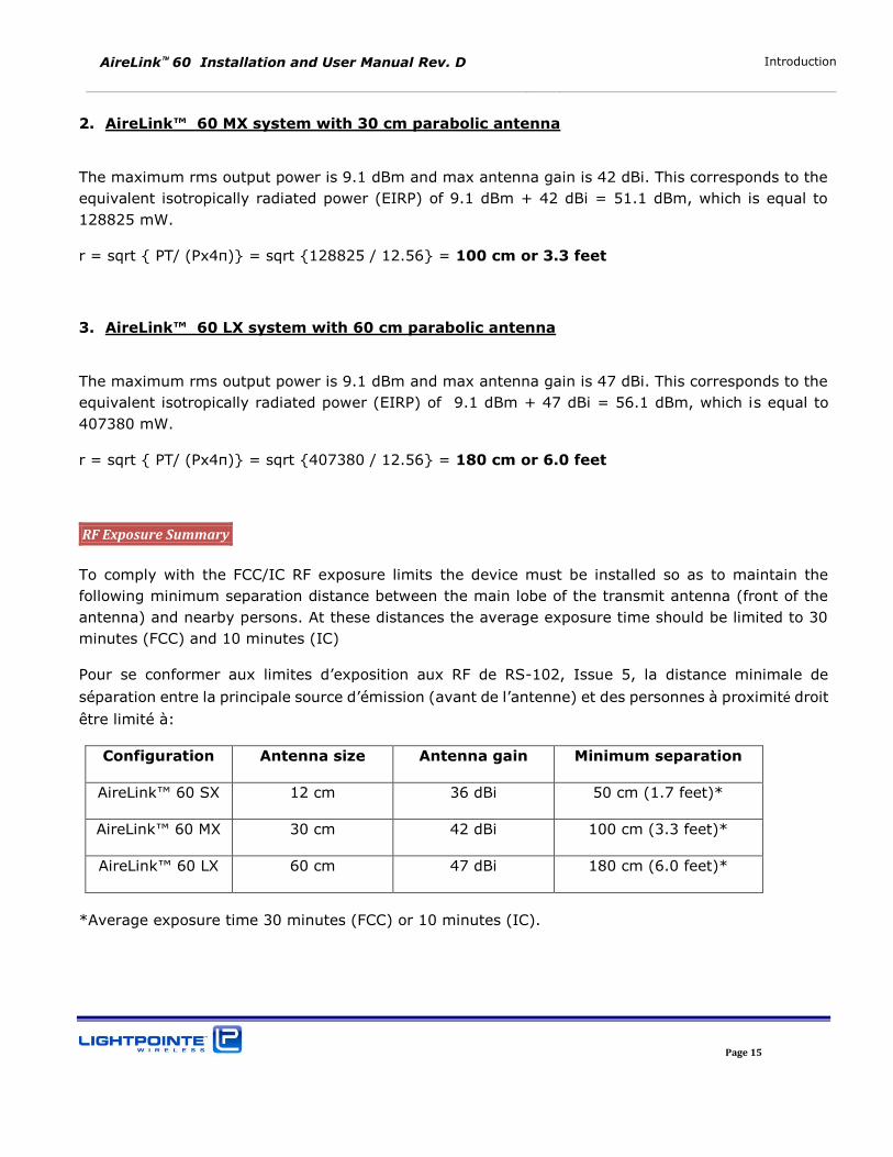
RF Exposure Summary
To comply with the FCC/IC RF exposure limits the device must be installed so as to maintain the
following minimum separation distance between the main lobe of the transmit antenna (front of the
antenna) and nearby persons. At these distances the average exposure time should be limited to 30
minutes (FCC) and 10 minutes (IC)
Pour se conformer aux limites d’exposition aux RF de RS-102, Issue 5, la distance minimale de
séparation entre la principale source d’émission (avant de l’antenne) et des personnes à proximité droit
être limité à:
Configuration Antenna size Antenna gain Minimum separation
AireLink™ 60 SX 12 cm 36 dBi 50 cm (1.7 feet)*
AireLink™ 60 MX 30 cm 42 dBi 100 cm (3.3 feet)*
AireLink™ 60 LX 60 cm 47 dBi 180 cm (6.0 feet)*
*Average exposure time 30 minutes (FCC) or 10 minutes (IC).
AireLink 60 Installation and User Manual Rev. D Introduction
Page 16
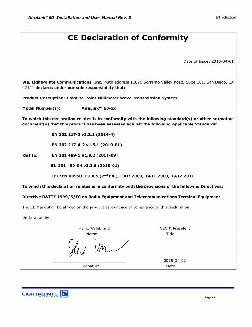
CE Declaration of Conformity
Date of Issue: 2015-04-01
We, LightPointe Communications, Inc., with address 11696 Sorrento Valley Road, Suite 101, San Diego, CA
92121 declares under our sole responsibility that:
Product Description: Point-to-Point Millimeter Wave Transmission System
Model Number(s): AireLink™ 60-xx
To which this declaration relates is in conformity with the following standard(s) or other normative
document(s) that this product has been assessed against the following Applicable Standards:
EN 302 217-3 v2.2.1 (2014-4)
EN 302 217-4-2 v1.5.1 (2010-01)
R&TTE: EN 301 489-1 V1.9.2 (2011-09)
EN 301 489-04 v2.2.0 (2015-01)
IEC/EN 60950-1:2005 (2nd Ed.), +A1: 2009, +A11:2009, +A12:2011
To which this declaration relates is in conformity with the provisions of the following Directives:
Directive R&TTE 1999/5/EC on Radio Equipment and Telecommunications Terminal Equipment
The CE Mark shall be affixed on the product as evidence of compliance to this declaration.
Declaration by:
Heinz Willebrand CEO & President
Name Title
_______________________________ 2015-04-01
Signature Date
AireLink 60 Installation and User Manual Rev. D Introduction
Page 17
Warranty Information
LightPointe warrants this product against faulty materials or workmanship under the terms of a
Standard Warranty and Support Agreement provided that the product was purchased directly from
LightPointe or from one of our authorized resellers. Please contact LightPointe Customer Service for
additional information or to obtain a copy of the Warranty Agreement.
Contacting LightPointe
Corporate Office
11696 Sorrento Valley Road, #101
San Diego, California 92121
P: 858.834.4083
F: 858.430.3458
Website: Hwww.LightPointe.com H
Email: [email protected]
AireLink 60 Installation and User Manual Rev. D Introduction
Page 18
1 INTRODUCTION
Before starting to cover details on how to install the system we will briefly review the system
components included with the shipment and explain the basic principle of operation.
1.1 SHIPPING CONTENT
The AireLink™ 60 system is shipped with an integrated or an external antenna. Depending on the system ordered packaging / box contents will be different.
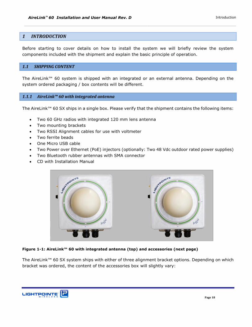
1.1.1 AireLink™ 60 with integrated antenna
The AireLink™ 60 SX ships in a single box. Please verify that the shipment contains the following items:
Two 60 GHz radios with integrated 120 mm lens antenna
Two mounting brackets
Two RSSI Alignment cables for use with voltmeter
Two ferrite beads
One Micro USB cable
Two Power over Ethernet (PoE) injectors (optionally: Two 48 Vdc outdoor rated power supplies)
Two Bluetooth rubber antennas with SMA connector
CD with Installation Manual
Figure 1-1: AireLink™ 60 with integrated antenna (top) and accessories (next page)
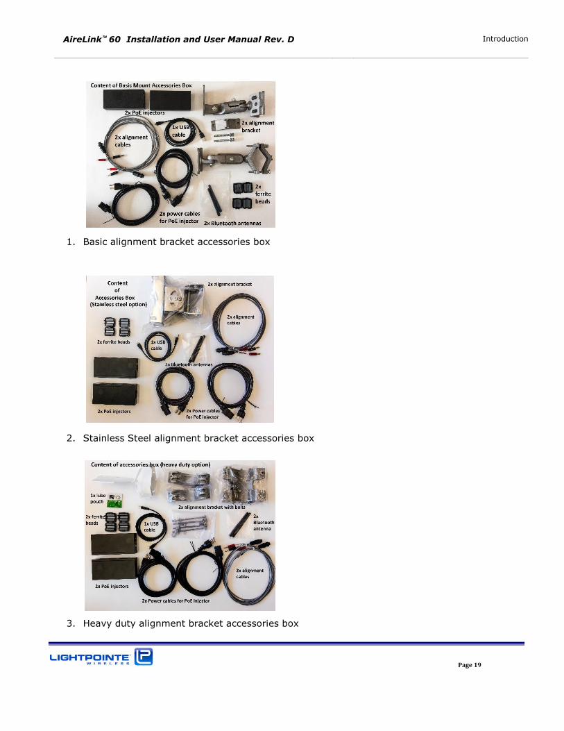
The AireLink™ 60 SX system ships with either of three alignment bracket options. Depending on which bracket was ordered, the content of the accessories box will slightly vary:
AireLink 60 Installation and User Manual Rev. D Introduction
Page 19
1. Basic alignment bracket accessories box
2. Stainless Steel alignment bracket accessories box
3. Heavy duty alignment bracket accessories box
AireLink 60 Installation and User Manual Rev. D Introduction
Page 20
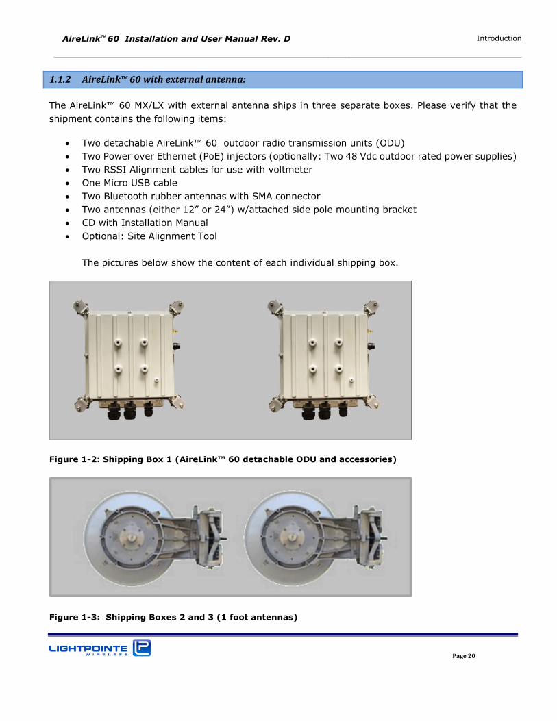
1.1.2 AireLink™ 60 with external antenna:
The AireLink™ 60 MX/LX with external antenna ships in three separate boxes. Please verify that the
shipment contains the following items:
Two detachable AireLink™ 60 outdoor radio transmission units (ODU)
Two Power over Ethernet (PoE) injectors (optionally: Two 48 Vdc outdoor rated power supplies)
Two RSSI Alignment cables for use with voltmeter
One Micro USB cable
Two Bluetooth rubber antennas with SMA connector
Two antennas (either 12” or 24”) w/attached side pole mounting bracket CD with Installation Manual
Optional: Site Alignment Tool
The pictures below show the content of each individual shipping box.
Figure 1-2: Shipping Box 1 (AireLink™ 60 detachable ODU and accessories)
Figure 1-3: Shipping Boxes 2 and 3 (1 foot antennas)
AireLink 60 Installation and User Manual Rev. D Introduction
Page 21
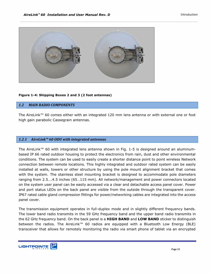
Figure 1-4: Shipping Boxes 2 and 3 (2 foot antennas)
1.2 MAIN RADIO COMPONENTS
The AireLink™ 60 comes either with an integrated 120 mm lens antenna or with external one or foot
high gain parabolic Cassegrain antennas.
1.2.1 AireLink™ 60 ODU with integrated antennas
The AireLink™ 60 with integrated lens antenna shown in Fig. 1-5 is designed around an aluminum-
based IP 66 rated outdoor housing to protect the electronics from rain, dust and other environmental
conditions. The system can be used to easily create a shorter distance point to point wireless Network
connection between remote locations. This highly integrated and outdoor rated system can be easily
installed at walls, towers or other structure by using the pole mount alignment bracket that comes
with the system. The stainless steel mounting bracket is designed to accommodate pole diameters
ranging from 2.5….4.5 inches (65…115 mm). All network/management and power connectors located
on the system user panel can be easily accessed via a clear and detachable access panel cover. Power
and port status LEDs on the back panel are visible from the outside through the transparent cover.
IP67 rated cable gland compression fittings for power/networking cables are integrated into the access
panel cover.
The transmission equipment operates in full-duplex mode and in slightly different frequency bands.
The lower band radio transmits in the 59 GHz frequency band and the upper band radio transmits in
the 62 GHz frequency band. On the back panel is a HIGH BAND and LOW BAND sticker to distinguish
between the radios. The AireLink™ 60 radios are equipped with a Bluetooth Low Energy (BLE) transceiver that allows for remotely monitoring the radio via smart phone of tablet via an encrypted
AireLink 60 Installation and User Manual Rev. D Introduction
Page 22
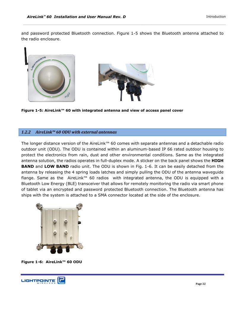
and password protected Bluetooth connection. Figure 1-5 shows the Bluetooth antenna attached to
the radio enclosure.
Figure 1-5: AireLink™ 60 with integrated antenna and view of access panel cover
1.2.2 AireLink™ 60 ODU with external antennas
The longer distance version of the AireLink™ 60 comes with separate antennas and a detachable radio
outdoor unit (ODU). The ODU is contained within an aluminum-based IP 66 rated outdoor housing to
protect the electronics from rain, dust and other environmental conditions. Same as the integrated
antenna solution, the radios operates in full-duplex mode. A sticker on the back panel shows the HIGH
BAND and LOW BAND radio unit. The ODU is shown in Fig. 1-6. It can be easily detached from the
antenna by releasing the 4 spring loads latches and simply pulling the ODU of the antenna waveguide
flange. Same as the AireLink™ 60 radios with integrated antenna, the ODU is equipped with a Bluetooth Low Energy (BLE) transceiver that allows for remotely monitoring the radio via smart phone
of tablet via an encrypted and password protected Bluetooth connection. The Bluetooth antenna has
ships with the system is attached to a SMA connector located at the side of the enclosure.
Figure 1-6: AireLink™ 60 ODU
AireLink 60 Installation and User Manual Rev. D Introduction
Page 23
The ODU is fully IP 67 outdoor rated and all network/management and power connectors can be easily
accessed via a clear and detachable access panel cover. The transparent cover also allows the see all
network port status indicators. The ODU can be easily removed from the antenna waveguide by
releasing 4 spring loaded latches. The ODU is the same for both, the 1 foot and the 2 foot antenna
system. By rotating the ODU 90 degrees the polarization can be changed easily. Chapter 4 describes
the ODU Networking, Service and Power Connections in more detail.
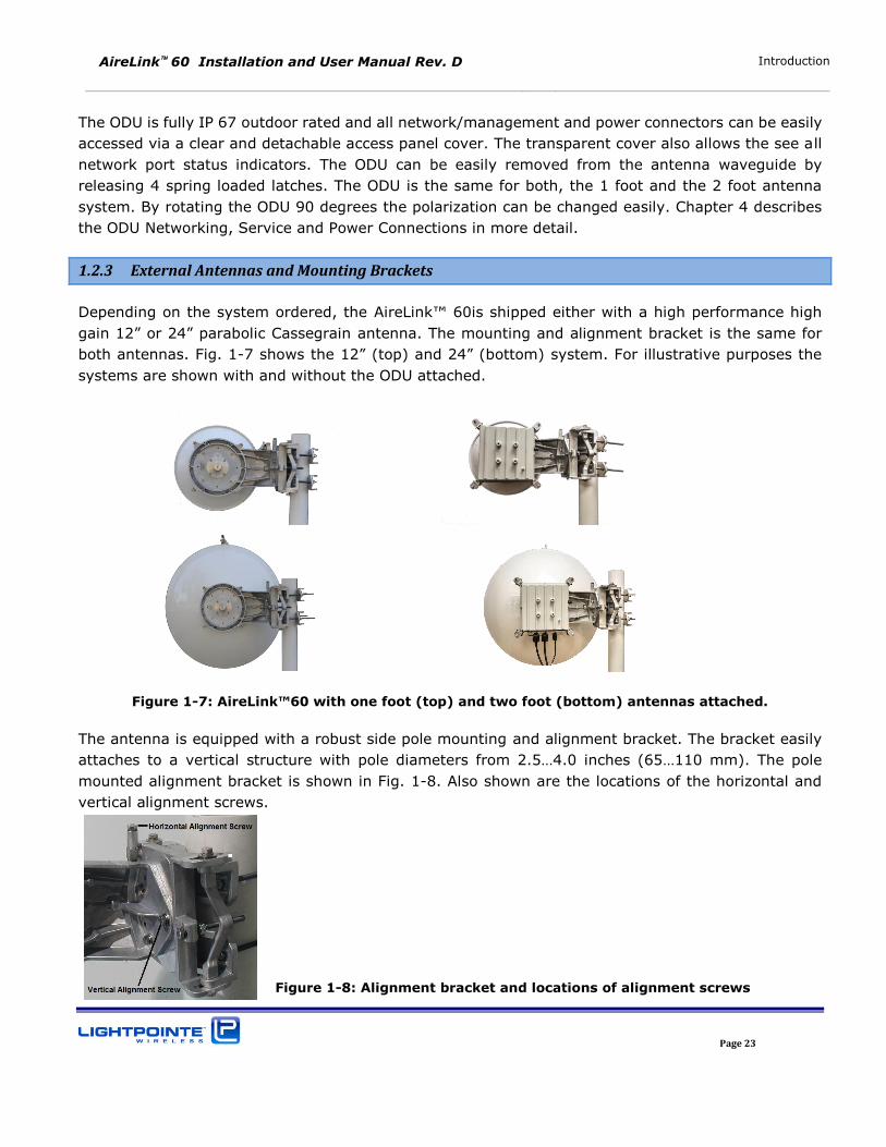
1.2.3 External Antennas and Mounting Brackets
Depending on the system ordered, the AireLink™ 60is shipped either with a high performance high
gain 12” or 24” parabolic Cassegrain antenna. The mounting and alignment bracket is the same for
both antennas. Fig. 1-7 shows the 12” (top) and 24” (bottom) system. For illustrative purposes the
systems are shown with and without the ODU attached.
Figure 1-7: AireLink™60 with one foot (top) and two foot (bottom) antennas attached.
The antenna is equipped with a robust side pole mounting and alignment bracket. The bracket easily
attaches to a vertical structure with pole diameters from 2.5…4.0 inches (65…110 mm). The pole
mounted alignment bracket is shown in Fig. 1-8. Also shown are the locations of the horizontal and
vertical alignment screws.
Figure 1-8: Alignment bracket and locations of alignment screws
AireLink 60 Installation and User Manual Rev. D Introduction
Page 24
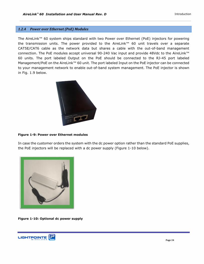
1.2.4 Power over Ethernet (PoE) Modules
The AireLink™ 60 system ships standard with two Power over Ethernet (PoE) injectors for powering
the transmission units. The power provided to the AireLink™ 60 unit travels over a separate
CAT5E/CAT6 cable as the network data but shares a cable with the out-of-band management
connection. The PoE modules accept universal 90-240 Vac input and provide 48Vdc to the AireLink™
60 units. The port labeled Output on the PoE should be connected to the RJ-45 port labeled
Management/PoE on the AireLink™ 60 unit. The port labeled Input on the PoE injector can be connected
to your management network to enable out-of-band system management. The PoE injector is shown
in Fig. 1.9 below.
Figure 1-9: Power over Ethernet modules
In case the customer orders the system with the dc power option rather than the standard PoE supplies,
the PoE injectors will be replaced with a dc power supply (Figure 1-10 below).
Figure 1-10: Optional dc power supply
AireLink 60 Installation and User Manual Rev. D Introduction
Page 25
1.2.5 Miscellaneous
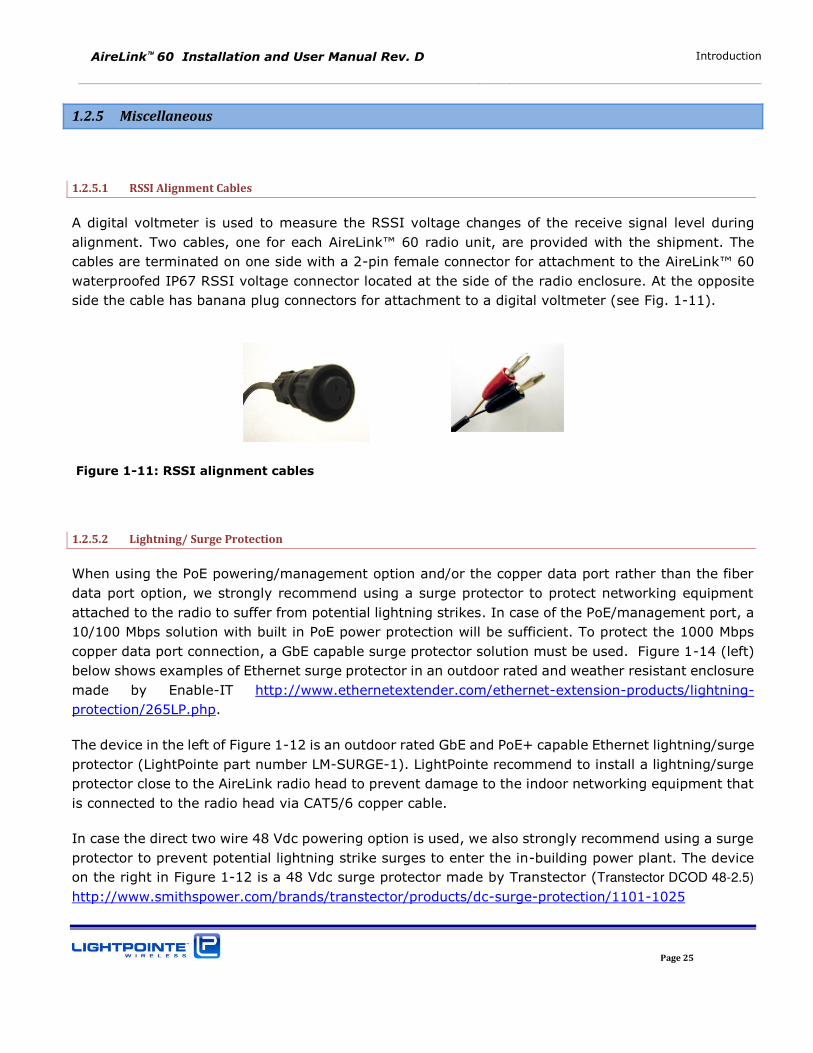
1.2.5.1 RSSI Alignment Cables
A digital voltmeter is used to measure the RSSI voltage changes of the receive signal level during
alignment. Two cables, one for each AireLink™ 60 radio unit, are provided with the shipment. The
cables are terminated on one side with a 2-pin female connector for attachment to the AireLink™ 60
waterproofed IP67 RSSI voltage connector located at the side of the radio enclosure. At the opposite
side the cable has banana plug connectors for attachment to a digital voltmeter (see Fig. 1-11).
Figure 1-11: RSSI alignment cables
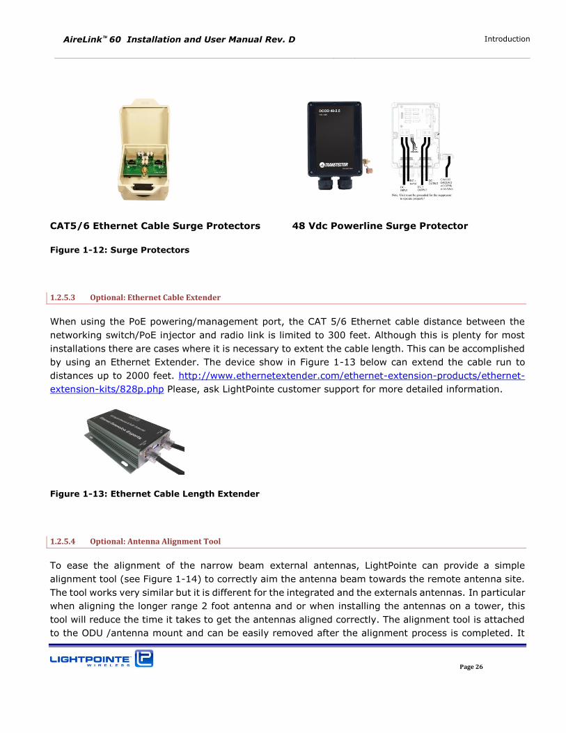
1.2.5.2 Lightning/ Surge Protection
When using the PoE powering/management option and/or the copper data port rather than the fiber
data port option, we strongly recommend using a surge protector to protect networking equipment
attached to the radio to suffer from potential lightning strikes. In case of the PoE/management port, a
10/100 Mbps solution with built in PoE power protection will be sufficient. To protect the 1000 Mbps
copper data port connection, a GbE capable surge protector solution must be used. Figure 1-14 (left)
below shows examples of Ethernet surge protector in an outdoor rated and weather resistant enclosure
made by Enable-IT http://www.ethernetextender.com/ethernet-extension-products/lightning-
protection/265LP.php.
The device in the left of Figure 1-12 is an outdoor rated GbE and PoE+ capable Ethernet lightning/surge
protector (LightPointe part number LM-SURGE-1). LightPointe recommend to install a lightning/surge
protector close to the AireLink radio head to prevent damage to the indoor networking equipment that
is connected to the radio head via CAT5/6 copper cable.
In case the direct two wire 48 Vdc powering option is used, we also strongly recommend using a surge
protector to prevent potential lightning strike surges to enter the in-building power plant. The device
on the right in Figure 1-12 is a 48 Vdc surge protector made by Transtector (Transtector DCOD 48-2.5)
http://www.smithspower.com/brands/transtector/products/dc-surge-protection/1101-1025
AireLink 60 Installation and User Manual Rev. D Introduction
Page 26
CAT5/6 Ethernet Cable Surge Protectors 48 Vdc Powerline Surge Protector
Figure 1-12: Surge Protectors
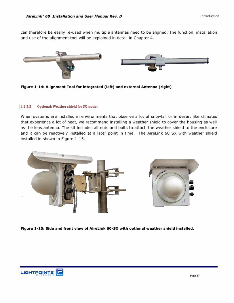
1.2.5.3 Optional: Ethernet Cable Extender
When using the PoE powering/management port, the CAT 5/6 Ethernet cable distance between the
networking switch/PoE injector and radio link is limited to 300 feet. Although this is plenty for most
installations there are cases where it is necessary to extent the cable length. This can be accomplished
by using an Ethernet Extender. The device show in Figure 1-13 below can extend the cable run to
distances up to 2000 feet. http://www.ethernetextender.com/ethernet-extension-products/ethernet-
extension-kits/828p.php Please, ask LightPointe customer support for more detailed information.
Figure 1-13: Ethernet Cable Length Extender
1.2.5.4 Optional: Antenna Alignment Tool
To ease the alignment of the narrow beam external antennas, LightPointe can provide a simple
alignment tool (see Figure 1-14) to correctly aim the antenna beam towards the remote antenna site.
The tool works very similar but it is different for the integrated and the externals antennas. In particular
when aligning the longer range 2 foot antenna and or when installing the antennas on a tower, this
tool will reduce the time it takes to get the antennas aligned correctly. The alignment tool is attached
to the ODU /antenna mount and can be easily removed after the alignment process is completed. It
AireLink 60 Installation and User Manual Rev. D Introduction
Page 27
can therefore be easily re-used when multiple antennas need to be aligned. The function, installation
and use of the alignment tool will be explained in detail in Chapter 4.
Figure 1-14: Alignment Tool for integrated (left) and external Antenna (right)
1.2.5.5 Optional: Weather shield for SX model
When systems are installed in environments that observe a lot of snowfall or in desert like climates
that experience a lot of heat, we recommend installing a weather shield to cover the housing as well
as the lens antenna. The kit includes all nuts and bolts to attach the weather shield to the enclosure
and it can be reactively installed at a later point in time. The AireLink 60 SX with weather shield
installed in shown in Figure 1-15.
Figure 1-15: Side and front view of AireLink 60-SX with optional weather shield installed.
AireLink 60 Installation and User Manual Rev. D Introduction
Page 28

AireLink 60 Installation and User Manual Rev. D Surveying the Installation Site
Page 29
2 SURVEYING THE INSTALLATION SITE
Chapter 2 educates the user on millimeter wave transmission technology and the site survey/review
process used in successful deployment of LightPointe AireLink™ 60 systems. Please read this chapter
before installing the system.
2.1 TOOLS
Please ensure that the following measures have been taken and that tools are available for surveying
the installation site.
Have permission of building owner to install the system
Ensure that the installation meets any local requirements
Use an accurately scaled map for locating sites and doing rough distance calculations
Laser range finder or GPS for accurate distance measurement (optional)
Binoculars to assist in locating opposite-end installation site
Sketch or notepad to make rough drawings and notes
Tape measure to determine approximate distance of fiber, power runs, etc.
Camera to take pictures of the installation sites (optional)
2.2 INSTALLATION SITE REVIEW
When performing a site review certain measures must be taken to ensure the successful deployment
of a millimeter wave transmission system.
Determine the appropriate system to meet the needs of each specific location:
Measure point-to-point distance using a map, a laser range finder or GPS coordinates
Refer to the ITU rain zone chart and locate the ITU rain zone where the system will be installed
Determine what physical connections will be required (e.g. SM/MM fiber or CAT5E/6 copper
cable, PoE or direct 48 Vdc)
Determine line-of-sight
Ensure that the antenna has sufficient path clearance. The Fresnel Zone is the area around the visual
line-of-sight that radio waves spread out into after they leave the antenna (see Figure 2-1). To
maintain good signal strength is important to maintain sufficient path clearance. Typically, a 20%
Fresnel Zone blockage introduces little signal. However, nearing 40% blockage the signal loss will
become significant.
AireLink 60 Installation and User Manual Rev. D Surveying the Installation Site
Page 30
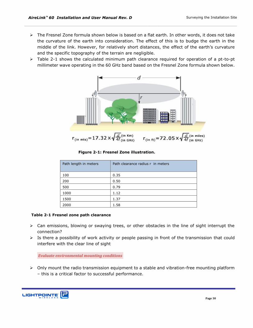
The Fresnel Zone formula shown below is based on a flat earth. In other words, it does not take
the curvature of the earth into consideration. The effect of this is to budge the earth in the
middle of the link. However, for relatively short distances, the effect of the earth’s curvature
and the specific topography of the terrain are negligible.
Table 2-1 shows the calculated minimum path clearance required for operation of a pt-to-pt
millimeter wave operating in the 60 GHz band based on the Fresnel Zone formula shown below.
Figure 2-1: Fresnel Zone illustration.
Path length in meters Path clearance radius r in meters
100 0.35
200 0.50
500 0.79
1000 1.12
1500 1.37
2000 1.58
Table 2-1 Fresnel zone path clearance
Can emissions, blowing or swaying trees, or other obstacles in the line of sight interrupt the
connection?
Is there a possibility of work activity or people passing in front of the transmission that could
interfere with the clear line of sight
Evaluate environmental mounting conditions
Only mount the radio transmission equipment to a stable and vibration-free mounting platform
– this is a critical factor to successful performance.
AireLink 60 Installation and User Manual Rev. D Surveying the Installation Site
Page 31
Evaluate that the foundation at the mounting location is not susceptible to change due to
humidity or temperature (avoid wooden mounting platforms)
Evaluate mounting locations for human access
Safe access to the radio transmission unit
Stable location/platform to stand upon
Safety considerations for installers and maintainers of the system in all weather conditions
Evaluate mounting locations to avoid interruptions of transmission
Near roof edge to avoid people walking in front of the transmission unit
Non-penetrating roof mount and at least 7 foot high to avoid people walking in front of the
transmission unit
Mounting the antenna in the middle of the roof and close to the roof surface can cause the
antenna to experience undesirable multi-path reflections
At the side or corner of a building wall without people being able to walk in front of the
transmission unit
Weather-protected location if possible
Safe location that will not be subject to damage from vandals
Evaluate mount stability
Solid concrete or steel structural building member
Directly on a flat roof surface if using a non-penetrating mount
Securely fastened to the side or top of parapet wall
2.3 LINK DISTANCE
Measurement of the link distance is important in estimating the link availability and calculating the
expected Receive Signal Level (RSL). When using a Global Positioning System (GPS) device this
measurement can be performed using the Latitude and Longitude coordinate readings from the
proposed locations of the antennas. When a GPS device is not available, online tools like Google Earth
are also very helpful to determine the link distance. However, GPS reading will be required in order to
comply with any required regulatory registration process.
To estimate maximum distances and availabilities for a given product and region please refer to the
AireLink™ Fade Margin/Availability charts shown in Chapter 2.5.
AireLink 60 Installation and User Manual Rev. D Surveying the Installation Site
Page 32
2.4 ANTENNA LOCATION
For proper operation and easy maintenance the optimum location for the antennas must be
determined. The ideal location should provide for ease of erecting and mounting the antenna, as well
as providing unimpeded LOS to the remote location. The following factors should be taken into account:
Type of mounting—fixed installation or non-penetrating roof pole mounting
Access location of fiber/RJ-45 cables and power wiring of the building
Length of cable runs
Earth Grounding connection points
Potential obstructions (also temporary), including allowances for tree growth
Accessibility of the radio mounting location
Accessibility of the site during and after working hours
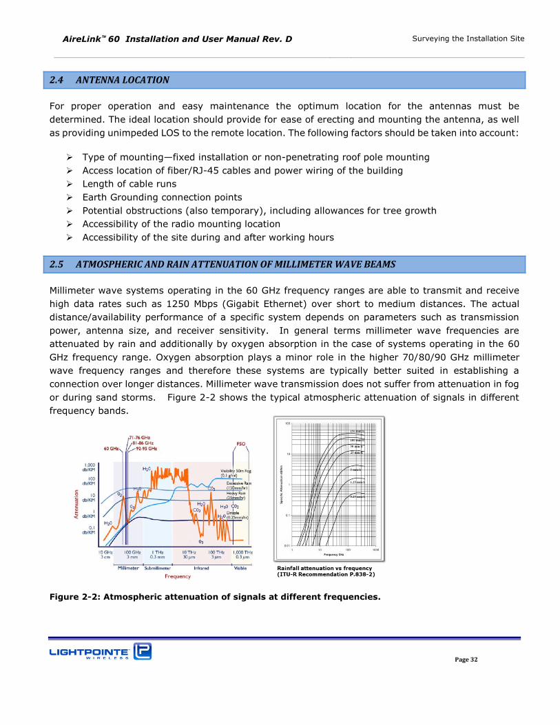
2.5 ATMOSPHERIC AND RAIN ATTENUATION OF MILLIMETER WAVE BEAMS
Millimeter wave systems operating in the 60 GHz frequency ranges are able to transmit and receive
high data rates such as 1250 Mbps (Gigabit Ethernet) over short to medium distances. The actual
distance/availability performance of a specific system depends on parameters such as transmission
power, antenna size, and receiver sensitivity. In general terms millimeter wave frequencies are
attenuated by rain and additionally by oxygen absorption in the case of systems operating in the 60
GHz frequency range. Oxygen absorption plays a minor role in the higher 70/80/90 GHz millimeter
wave frequency ranges and therefore these systems are typically better suited in establishing a
connection over longer distances. Millimeter wave transmission does not suffer from attenuation in fog
or during sand storms. Figure 2-2 shows the typical atmospheric attenuation of signals in different
frequency bands.
Figure 2-2: Atmospheric attenuation of signals at different frequencies.

AireLink 60 Installation and User Manual Rev. D Surveying the Installation Site
Page 33
Rain attenuation of millimeter wave signals has been studied extensively over several decades and
models are available to reliably predict the availability of a millimeter wave transmission system in
various rain zones around the world. Based on the actual rain rates collected in specific regions, the
International Telecommunications Union (ITU) has published charts dividing the globe into separate
rainfall regions. Similar charts with slightly different geographical breakdowns exist, based on the work
of the researcher Crane. Both charts can be used to predict availability performance of millimeter wave
transmission systems. Figure 2-3 shows the ITU chart of different rain rate regions of the world. The
regions are divided by using an alphanumerical notation with region A having the least and region Q
having the highest rain fall rates. Naturally the highest rain rates occur around the equator (rain zones
N, P, Q) and in these regions rain rates up to 250 mm/h can be observed for very short periods of
time. Very low rain rates (rain zone A) can be observed in the African, Middle Eastern and Asian dessert
regions as well as in the Northern Polar regions.
Figure 2-3: ITU rain zone chart of the earth
Using the ITU or Crane rain zone charts one can calculate the availability of a millimeter wave
transmission system in a specific rain zone. When it comes to rain attenuation it is important to keep
in mind that the rain fall rate and not the total amount of yearly rainfall determines the availability of
a millimeter wave radio system. For example, it is well known that the number of rainy days in the
North Western region of the United States and in cities like Seattle greatly exceeds the number of rainy
days in the South Eastern areas like Florida. However, when looking at Table 2-2, representing the
actual duration of peak rain fall rates in mm/hour in different rain zones, one finds that the rain fall
rate (or rain intensity) in the North Western region of the United States is far less when compared to
AireLink 60 Installation and User Manual Rev. D Surveying the Installation Site
Page 34
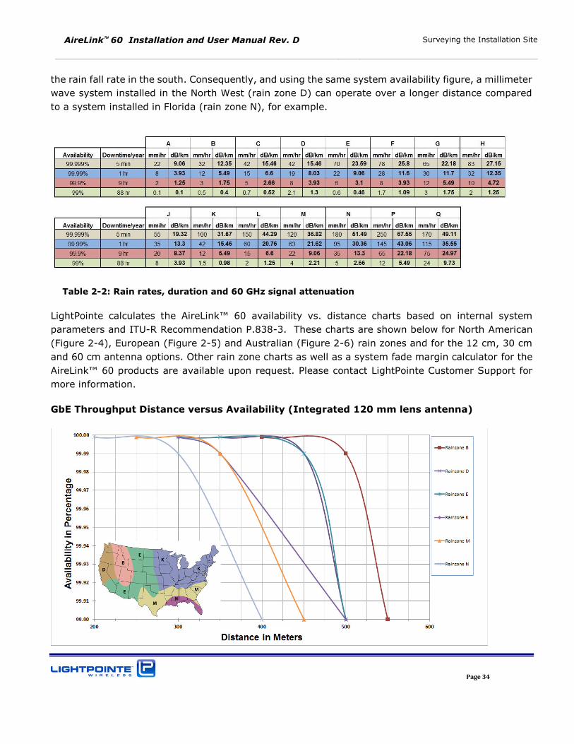
the rain fall rate in the south. Consequently, and using the same system availability figure, a millimeter
wave system installed in the North West (rain zone D) can operate over a longer distance compared
to a system installed in Florida (rain zone N), for example.
Table 2-2: Rain rates, duration and 60 GHz signal attenuation
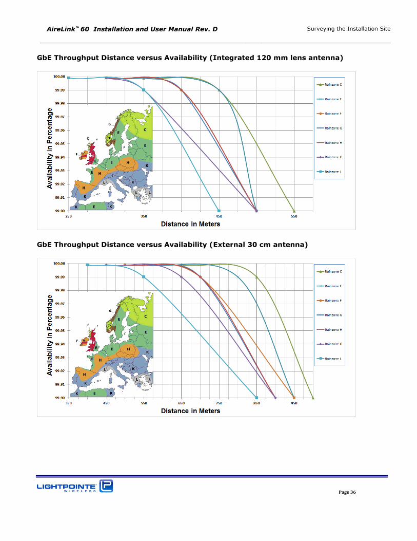
LightPointe calculates the AireLink™ 60 availability vs. distance charts based on internal system
parameters and ITU-R Recommendation P.838-3. These charts are shown below for North American
(Figure 2-4), European (Figure 2-5) and Australian (Figure 2-6) rain zones and for the 12 cm, 30 cm
and 60 cm antenna options. Other rain zone charts as well as a system fade margin calculator for the
AireLink™ 60 products are available upon request. Please contact LightPointe Customer Support for
more information.
GbE Throughput Distance versus Availability (Integrated 120 mm lens antenna)
AireLink 60 Installation and User Manual Rev. D Surveying the Installation Site
Page 35
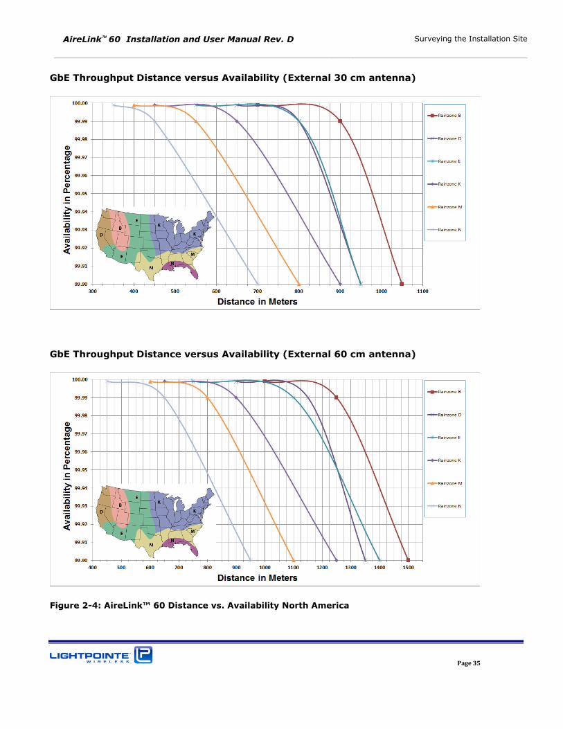
GbE Throughput Distance versus Availability (External 30 cm antenna)
GbE Throughput Distance versus Availability (External 60 cm antenna)
Figure 2-4: AireLink™ 60 Distance vs. Availability North America
AireLink 60 Installation and User Manual Rev. D Surveying the Installation Site
Page 36
GbE Throughput Distance versus Availability (Integrated 120 mm lens antenna)
GbE Throughput Distance versus Availability (External 30 cm antenna)
AireLink 60 Installation and User Manual Rev. D Surveying the Installation Site
Page 37
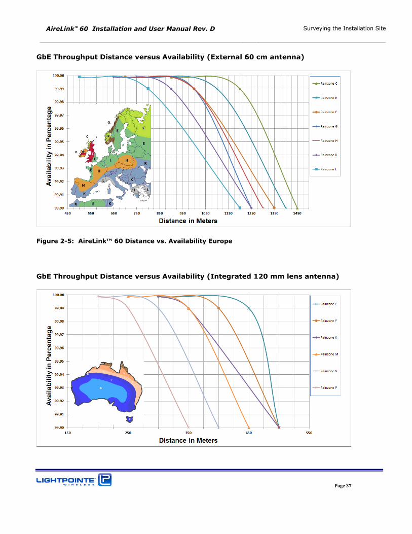
GbE Throughput Distance versus Availability (External 60 cm antenna)
Figure 2-5: AireLink™ 60 Distance vs. Availability Europe
GbE Throughput Distance versus Availability (Integrated 120 mm lens antenna)
AireLink 60 Installation and User Manual Rev. D Surveying the Installation Site
Page 38
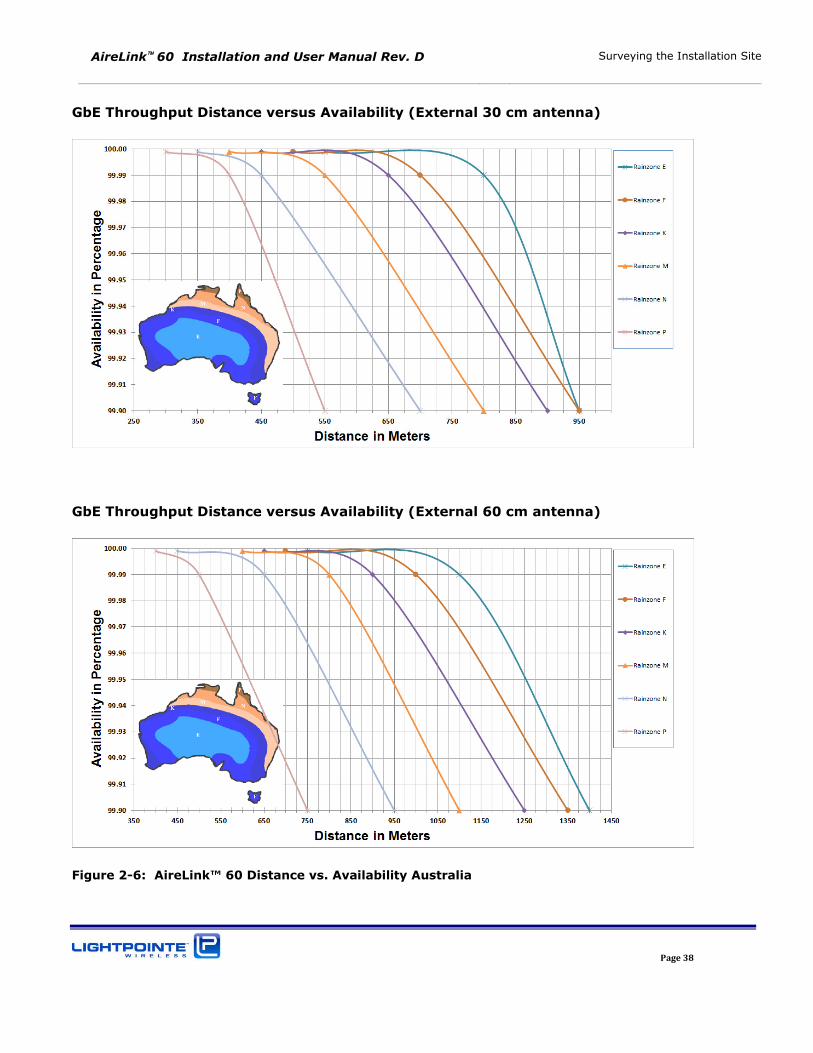
GbE Throughput Distance versus Availability (External 30 cm antenna)
GbE Throughput Distance versus Availability (External 60 cm antenna)
Figure 2-6: AireLink™ 60 Distance vs. Availability Australia
AireLink 60 Installation and User Manual Rev. D Surveying the Installation Site
Page 39
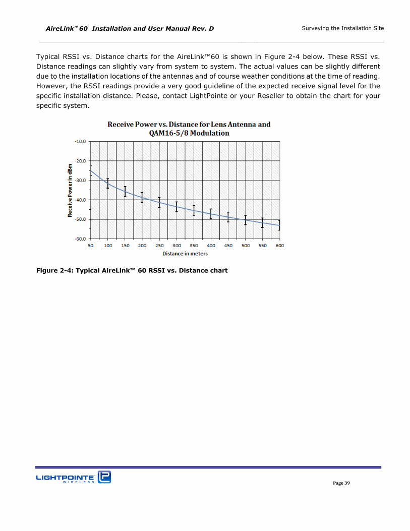
Typical RSSI vs. Distance charts for the AireLink™60 is shown in Figure 2-4 below. These RSSI vs.
Distance readings can slightly vary from system to system. The actual values can be slightly different
due to the installation locations of the antennas and of course weather conditions at the time of reading.
However, the RSSI readings provide a very good guideline of the expected receive signal level for the
specific installation distance. Please, contact LightPointe or your Reseller to obtain the chart for your
specific system.
Figure 2-4: Typical AireLink™ 60 RSSI vs. Distance chart
AireLink 60 Installation and User Manual Rev. D Surveying the Installation Site
Page 40
AireLink 60 Installation and User Manual Rev. D Networking, Power and Service Connections
Page 41
3 NETWORKING, POWER AND SERVICE CONNECTIONS
The AireLink™ 60 with integrated 12 cm antenna and the systems with external 1 or 2 foot antennas
have the same networking, power and service connections. In case of the external antenna solution
the radio itself comes as a fully outdoor rated ODU that is attached to the antenna base using 4 spring
loaded latches (see Figure 1-7). Please, review Chapter 1 in case there are questions regarding the
general system/ODU design.
At this point, we recommend that the user/installer gets familiar with the user panel and connectors
before installing the system on the roof/tower. The user panel can be easily accessed by using a Philips
screwdriver and remove the 4 screws that attach the clear access panel cover the radio housing (see
Figure 1-5). In case the system ordered is the external antenna version, we recommend removing the
ODU from the antenna Base by releasing the 4 spring loaded ODU latches and pulling the ODU of the
antenna waveguide flange. This allows the user taking a closer look at the ODU and start the process
of preconfiguring the system before installing on the roof.
Note
We recommend pre-configuring the system before installing it on the
roof. This relatively simple process requires powering up the system and
being familiar with the use of a serial interface program such as Windows
based HyperTerminal or PuTTY
http://www.chiark.greenend.org.uk/~sgtatham/putty/download.html
The connection to the serial port is done via the USB port and the
customer needs to download and install the appropriate USB to UART
Bridge Virtual COM Port (VCP) drivers from Silicon labs.
http://wwwqa.silabs.com/products/mcu/Pages/usbtouartbridgevcpdrivers.aspx
3.1 AIRELINK™ 60 USER PANEL
The AireLink™ 60 user panel is identical for the integrated and external radio solution where it is part
of the ODU. The user panel is located at the side of the housing and a transparent hard plastic cover
protects the user panel from being exposed to the environment. The plastic cover is fitted with a rubber
seal to ensure a watertight connection with the radio enclosure, and also has 3 integrated and IP67
rated compression fitted cable glands for:
+/- 48 Vdc Power Cable
PoE & Management Cable
Copper or Fiber Data Network Cable
AireLink 60 Installation and User Manual Rev. D Networking, Power and Service Connections
Page 42
The diameters of the glands are large enough to accept a wide variety of cable diameters and even
pre-connectorized cable.
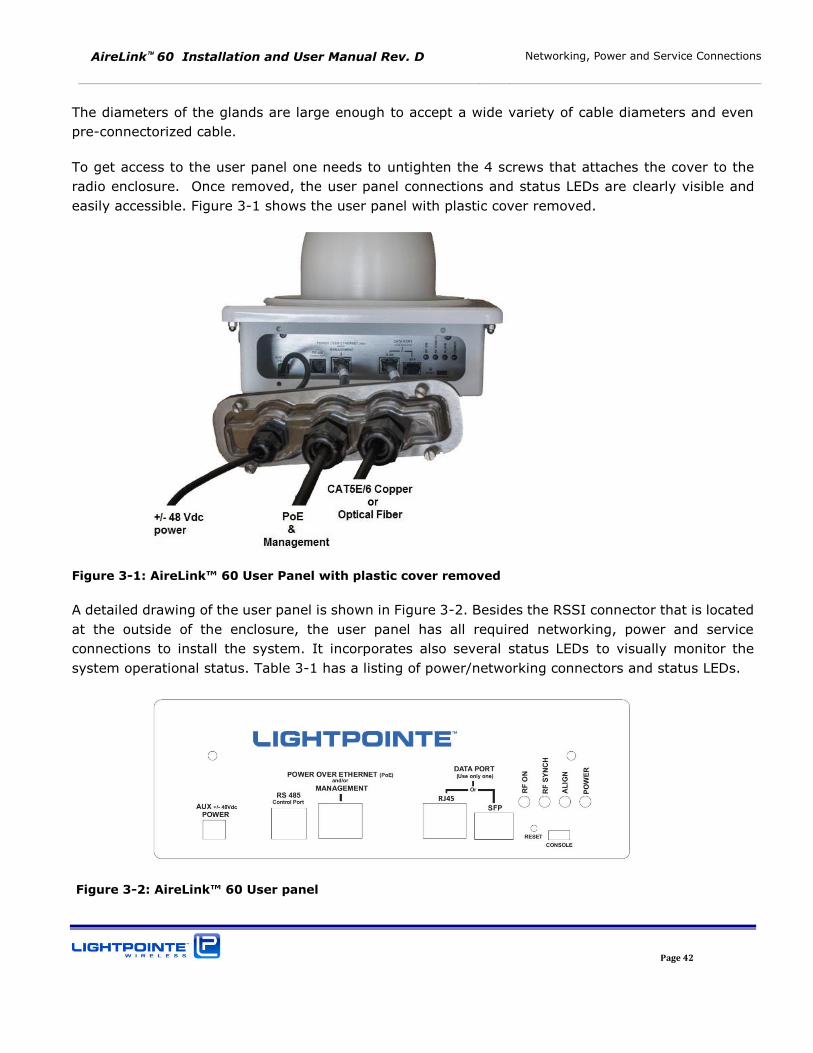
To get access to the user panel one needs to untighten the 4 screws that attaches the cover to the
radio enclosure. Once removed, the user panel connections and status LEDs are clearly visible and
easily accessible. Figure 3-1 shows the user panel with plastic cover removed.
Figure 3-1: AireLink™ 60 User Panel with plastic cover removed
A detailed drawing of the user panel is shown in Figure 3-2. Besides the RSSI connector that is located
at the outside of the enclosure, the user panel has all required networking, power and service
connections to install the system. It incorporates also several status LEDs to visually monitor the
system operational status. Table 3-1 has a listing of power/networking connectors and status LEDs.
Figure 3-2: AireLink™ 60 User panel
AireLink 60 Installation and User Manual Rev. D Networking, Power and Service Connections
Page 43
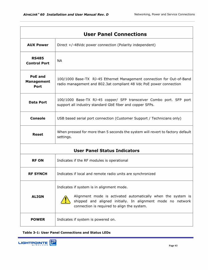
User Panel Connections
AUX Power Direct +/-48Vdc power connection (Polarity independent)
RS485
Control Port NA
PoE and
Management
Port
100/1000 Base-TX RJ-45 Ethernet Management connection for Out-of-Band
radio management and 802.3at compliant 48 Vdc PoE power connection
Data Port 100/1000 Base-TX RJ-45 copper/ SFP transceiver Combo port. SFP port
support all industry standard GbE fiber and copper SFPs.
Console USB based serial port connection (Customer Support / Technicians only)
Reset When pressed for more than 5 seconds the system will revert to factory default
settings.
User Panel Status Indicators
RF ON Indicates if the RF modules is operational
RF SYNCH Indicates if local and remote radio units are synchronized
ALIGN
Indicates if system is in alignment mode.
Alignment mode is activated automatically when the system is
shipped and aligned initially. In alignment mode no network
connection is required to align the system.
POWER Indicates if system is powered on.
Table 3-1: User Panel Connections and Status LEDs
AireLink 60 Installation and User Manual Rev. D Networking, Power and Service Connections
Page 44
3.2 POWER CONNECTION
There are two options to power the radio:
1. Power over Ethernet (PoE) Use 802.3at compatible PoE switch or Lightpointe high power
passive PoE injector (see Fig. 1-4) and connect to PoE and Management Port.
2. Direct +/-48 Vdc Use Lightpointe 48 Vdc power supply shown in Figure 1-5 and connect to
the AUX power port.
Note
Power redundancy operation can be achieved by connecting a PoE and
a 48 Vdc power supply in parallel. To ensure uninterrupted power in case
of a power failure on either power line without system restart, please
connect the PoE power first and wait until the system boot is completed
before connecting the 48Vdc power line.
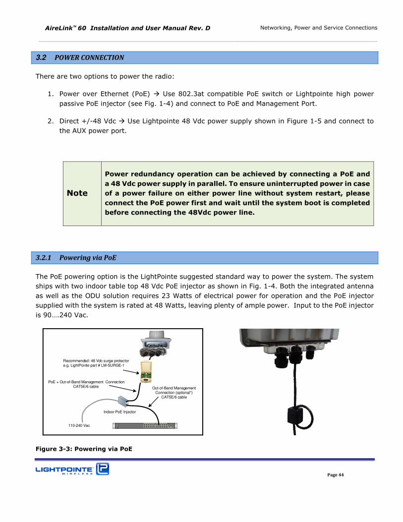
3.2.1 Powering via PoE
The PoE powering option is the LightPointe suggested standard way to power the system. The system
ships with two indoor table top 48 Vdc PoE injector as shown in Fig. 1-4. Both the integrated antenna
as well as the ODU solution requires 23 Watts of electrical power for operation and the PoE injector
supplied with the system is rated at 48 Watts, leaving plenty of ample power. Input to the PoE injector
is 90….240 Vac.
MXA
SPEED
DUPLX
STAT
SYST
RPS
Catalyst 2960 Series21 43 65 87 109 1211 1413 1615 1817 2019 2221 2423
1 2
2X
1X
12X
11X
14X
13X
24X
23X
Indoor PoE Injector
110-240 Vac
PoE + Out-of-Band Management ConnectionCAT5E/6 cable Out-of-Band Management
Connection (optional*)CAT5E/6 cable
Recommended: 48 Vdc surge protector e.g. LightPointe part # LM-SURGE-1
Figure 3-3: Powering via PoE
AireLink 60 Installation and User Manual Rev. D Networking, Power and Service Connections
Page 45
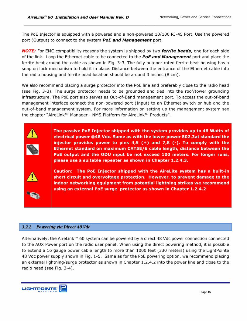
The PoE Injector is equipped with a powered and a non-powered 10/100 RJ-45 Port. Use the powered
port (Output) to connect to the system PoE and Management port.
NOTE: For EMC compatibility reasons the system is shipped by two ferrite beads, one for each side
of the link. Loop the Ethernet cable to be connected to the PoE and Management port and place the
ferrite beat around the cable as shown in Fig. 3-3. The fully outdoor rated ferrite beat housing has a
snap on lock mechanism to hold it in place. Distance between the entrance of the Ethernet cable into
the radio housing and ferrite bead location should be around 3 inches (8 cm).
We also recommend placing a surge protector into the PoE line and preferably close to the radio head
(see Fig. 3-3). The surge protector needs to be grounded and tied into the roof/tower grounding
infrastructure. The PoE port also serves as Out-of-Band management port. To access the out-of-band
management interface connect the non-powered port (Input) to an Ethernet switch or hub and the
out-of-band management system. For more information on setting up the management system see
the chapter “AireLink™ Manager - NMS Platform for AireLink™ Products”.
The passive PoE Injector shipped with the system provides up to 48 Watts of
electrical power @48 Vdc. Same as with the lower power 802.3at standard the
injector provides power to pins 4,5 (+) and 7,8 (-). To comply with the
Ethernet standard on maximum CAT5E/6 cable length, distance between the
PoE output and the ODU input be not exceed 100 meters. For longer runs,
please use a suitable repeater as shown in Chapter 1.2.4.3.
Caution: The PoE Injector shipped with the AireLite system has a built-in
short circuit and overvoltage protection. However, to prevent damage to the
indoor networking equipment from potential lightning strikes we recommend
using an external PoE surge protector as shown in Chapter 1.2.4.2
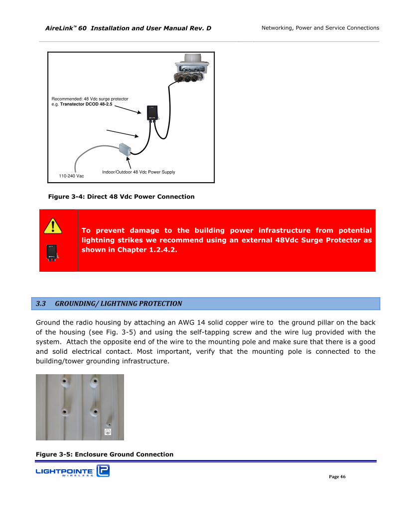
3.2.2 Powering via Direct 48 Vdc
Alternatively, the AireLink™ 60 system can be powered by a direct 48 Vdc power connection connected
to the AUX Power port on the radio user panel. When using the direct powering method, it is possible
to extend a 16 gauge power cable length to more than 1000 feet (330 meters) using the LightPointe
48 Vdc power supply shown in Fig. 1-5. Same as for the PoE powering option, we recommend placing
an external lightning/surge protector as shown in Chapter 1.2.4.2 into the power line and close to the
radio head (see Fig. 3-4).
AireLink 60 Installation and User Manual Rev. D Networking, Power and Service Connections
Page 46
Recommended: 48 Vdc surge protector
e.g. Transtector DCOD 48-2.5
Indoor/Outdoor 48 Vdc Power Supply110-240 Vac
Figure 3-4: Direct 48 Vdc Power Connection
To prevent damage to the building power infrastructure from potential
lightning strikes we recommend using an external 48Vdc Surge Protector as
shown in Chapter 1.2.4.2.
3.3 GROUNDING/ LIGHTNING PROTECTION
Ground the radio housing by attaching an AWG 14 solid copper wire to the ground pillar on the back
of the housing (see Fig. 3-5) and using the self-tapping screw and the wire lug provided with the
system. Attach the opposite end of the wire to the mounting pole and make sure that there is a good
and solid electrical contact. Most important, verify that the mounting pole is connected to the
building/tower grounding infrastructure.
Figure 3-5: Enclosure Ground Connection
AireLink 60 Installation and User Manual Rev. D Networking, Power and Service Connections
Page 47
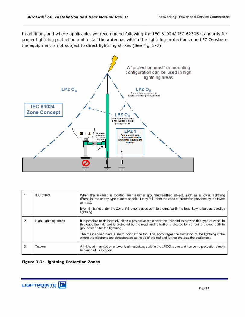
In addition, and where applicable, we recommend following the IEC 61024/ IEC 62305 standards for
proper lightning protection and install the antennas within the lightning protection zone LPZ OB where
the equipment is not subject to direct lightning strikes (See Fig. 3-7).
1 IEC 61024 When the linkhead is located near another grounded/earthed object, such as a tower, lightning (Franklin) rod or any type of mast or pole, it may fall under the zone of protection provided by the tower or mast.
Even if it is not under the Zone, if it is not a good path to ground/earth it is less likely to be destroyed by lightning.
2 High Lightning zones It is possible to deliberately place a protective mast near the linkhead to provide this type of zone. In this case the linkhead is protected by the mast and is further protected by not being a good path to ground/earth for the lightning.
The mast should have a sharp point at the top. This encourages the formation of the lightning strike where the electrons are concentrated at the tip of the rod and further protects the equipment
3 Towers A linkhead mounted on a tower is almost always within the LPZ OB zone and has some protection simply because of its location.
Figure 3-7: Lightning Protection Zones
AireLink 60 Installation and User Manual Rev. D Networking, Power and Service Connections
Page 48
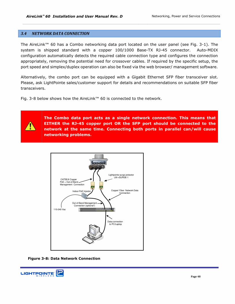
3.4 NETWORK DATA CONNECTION
The AireLink™ 60 has a Combo networking data port located on the user panel (see Fig. 3-1). The
system is shipped standard with a copper 100/1000 Base-TX RJ-45 connector. Auto-MDIX
configuration automatically detects the required cable connection type and configures the connection
appropriately, removing the potential need for crossover cables. If required by the specific setup, the
port speed and simplex/duplex operation can also be fixed via the web browser/ management software.
Alternatively, the combo port can be equipped with a Gigabit Ethernet SFP fiber transceiver slot.
Please, ask LightPointe sales/customer support for details and recommendations on suitable SFP fiber
transceivers.
Fig. 3-8 below shows how the AireLink™ 60 is connected to the network.
`
MXA
SPEED
DUPLX
STAT
SYST
RPS
Catalyst 2960 Series21 43 65 87 109 1211 1413 1615 1817 2019 2221 2423
1 2
2X
1X
12X
11X
14X
13X
24X
23X
Indoor PoE Injector
110-240 Vac
CAT5E/6 CopperPoE + Out-of-Band Management Connection
Out-of-Band Management Connection (optional*)
Data connection to PC/Laptop
Copper/ Fiber Network Data Connection
Lightpointe surge protectorLM-=SURGE-1
Figure 3-8: Data Network Connection
The Combo data port acts as a single network connection. This means that
EITHER the RJ-45 copper port OR the SFP port should be connected to the
network at the same time. Connecting both ports in parallel can/will cause
networking problems.
AireLink 60 Installation and User Manual Rev. D Networking, Power and Service Connections
Page 49
3.5 OUT-OF-BAND MANAGEMENT CONNECTION
The AireLink™60 Out-of-Band management connection shares the RJ45 100/1000Base-TX PoE
powering port provided via a CAT5/6 twisted pair Ethernet cable. To get access to the AireLink™
management system the input port of the PoE module must be connected to your management
network.
The Ethernet cable length of the management cable from the AireLink™ 60 radio to the switch or router
should not exceed 100 meters due to Ethernet compliance issues. Otherwise a suitable Ethernet
repeating device as shown in Chapter 1.2.4.3 must be used.
In Chapter 4 the AireLink™ Manager will be described in more detail.
3.6 CONSOLE PORT
The user panel micro USB based Console port is used to establish a serial port connection to a PC/laptop
and the shipment contains a micro USB2.0 cable to establish the connection. The serial port is used
by customer support personal / technicians for advanced troubleshooting purposes. It is therefore not
necessary to pull cable for the serial port during installation. All setup and management functions can
be performed over the AireLink™ Manager web-console, Telnet or SNMP. Before accessing the serial
connection the user/installer needs to download and install the appropriate USB to UART Bridge Virtual
COM Port (VCP) drivers from the Silicon Labs webpage at
http://wwwqa.silabs.com/products/mcu/Pages/usbtouartbridgevcpdrivers.aspx. After installation of
the driver the serial port is accessible via a serial port communications program such as HyperTerminal
or PuTTY.
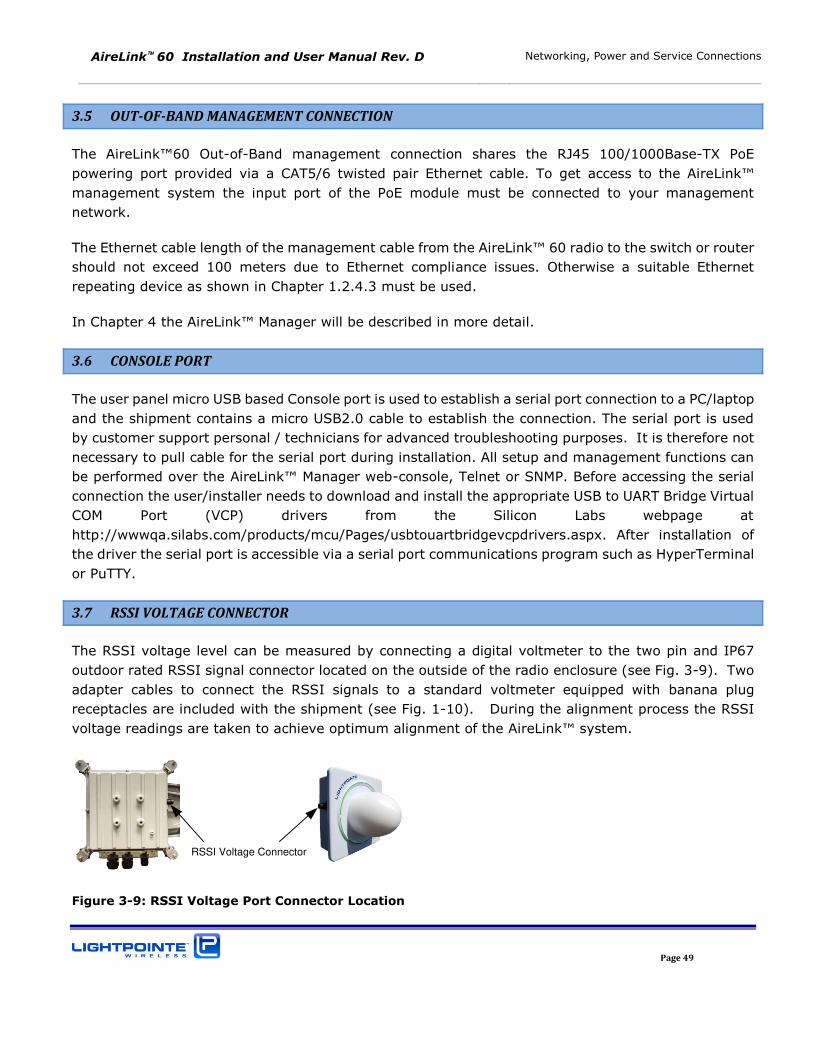
3.7 RSSI VOLTAGE CONNECTOR
The RSSI voltage level can be measured by connecting a digital voltmeter to the two pin and IP67
outdoor rated RSSI signal connector located on the outside of the radio enclosure (see Fig. 3-9). Two
adapter cables to connect the RSSI signals to a standard voltmeter equipped with banana plug
receptacles are included with the shipment (see Fig. 1-10). During the alignment process the RSSI
voltage readings are taken to achieve optimum alignment of the AireLink™ system.
RSSI Voltage Connector
Figure 3-9: RSSI Voltage Port Connector Location
AireLink 60 Installation and User Manual Rev. D Networking, Power and Service Connections
Page 50
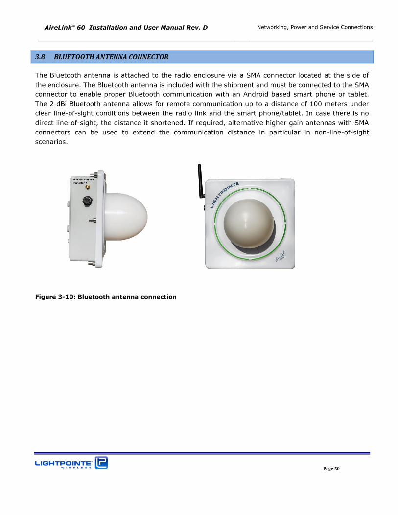
3.8 BLUETOOTH ANTENNA CONNECTOR
The Bluetooth antenna is attached to the radio enclosure via a SMA connector located at the side of
the enclosure. The Bluetooth antenna is included with the shipment and must be connected to the SMA
connector to enable proper Bluetooth communication with an Android based smart phone or tablet.
The 2 dBi Bluetooth antenna allows for remote communication up to a distance of 100 meters under
clear line-of-sight conditions between the radio link and the smart phone/tablet. In case there is no
direct line-of-sight, the distance it shortened. If required, alternative higher gain antennas with SMA
connectors can be used to extend the communication distance in particular in non-line-of-sight
scenarios.
Figure 3-10: Bluetooth antenna connection
AireLink 60 Installation and User Manual Rev. D Networking, Power and Service Connections
Page 51
AireLink 60 Installation and User Manual Rev. D Recommended Software Pre-Configurations
Page 52
4 RECOMMENDED SOFTWARE PRE-CONFIGURATIONS
Before installing the radio on the roof, we recommend to perform a few simple software pre-
configurations. These basic settings are important to access the management interface/web browser.
4.1 REQUIRED NETWORK SETTINGS INFO
Please, ask the Network Administrator to provide the following information:
1. IP Address for both 60 GHz radios(Pre-configured IP address is 192.168.1.10)
2. Subnet Mask (Pre-configured subnet mask is 255.255.255.0)
3. Default Gateway Address (Pre-configured gateway address is 192.168.1.1)
4. Password for CLI access (default password is admin)
5. Password for WEB BROWSER access (default password is admin)
Besides these basic settings, additional settings (e.g. SNMP community settings, VLAN settings, etc.)
can be configured via the TELNET CLI interface (see Chapter 7.). Alternatively, configuration changes
can be performed via the web browser interface (see Chapter 6.).
4.2 AIRELINK CONFIGURATION VIA TELNET CLI INTERFACE
Please perform the following steps to connect the ODU to the serial port:
Step 1
Connect the AireLink Management and PoE Port to the Output of the PoE
Injector using a straight-through Cat5E cable. Plug the PoE Injector into a 110
or 240VAC outlet. The AireLink system will now power up and initialize.
Depending on the software load this process can take up to 2 minutes.
The boot process is completed when the Power LED on the back panel
(see Figure 3-2) stops blinking and is solid green.
AireLink 60 Installation and User Manual Rev. D Recommended Software Pre-Configurations
Page 53
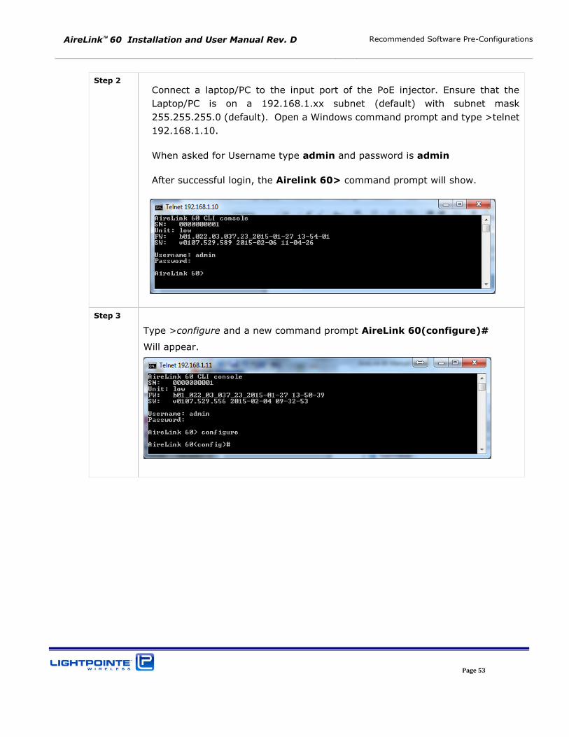
Step 2
Connect a laptop/PC to the input port of the PoE injector. Ensure that the
Laptop/PC is on a 192.168.1.xx subnet (default) with subnet mask
255.255.255.0 (default). Open a Windows command prompt and type >telnet
192.168.1.10.
When asked for Username type admin and password is admin
After successful login, the Airelink 60> command prompt will show.
Step 3
Type >configure and a new command prompt AireLink 60(configure)#
Will appear.
AireLink 60 Installation and User Manual Rev. D Recommended Software Pre-Configurations
Page 54
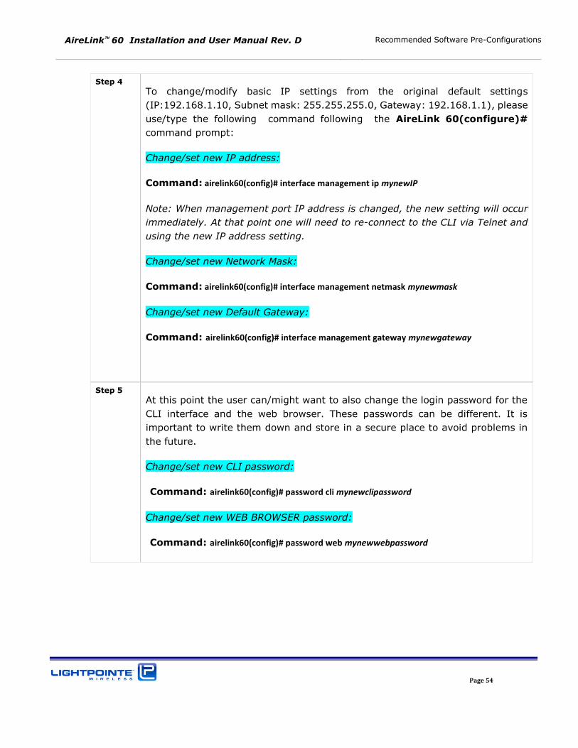
Step 4
To change/modify basic IP settings from the original default settings
(IP:192.168.1.10, Subnet mask: 255.255.255.0, Gateway: 192.168.1.1), please
use/type the following command following the AireLink 60(configure)#
command prompt:
Change/set new IP address:
Command: airelink60(config)# interface management ip mynewIP
Note: When management port IP address is changed, the new setting will occur
immediately. At that point one will need to re-connect to the CLI via Telnet and
using the new IP address setting.
Change/set new Network Mask:
Command: airelink60(config)# interface management netmask mynewmask
Change/set new Default Gateway:
Command: airelink60(config)# interface management gateway mynewgateway
Step 5
At this point the user can/might want to also change the login password for the
CLI interface and the web browser. These passwords can be different. It is
important to write them down and store in a secure place to avoid problems in
the future.
Change/set new CLI password:
Command: airelink60(config)# password cli mynewclipassword
Change/set new WEB BROWSER password:
Command: airelink60(config)# password web mynewwebpassword
AireLink 60 Installation and User Manual Rev. D Recommended Software Pre-Configurations
Page 55
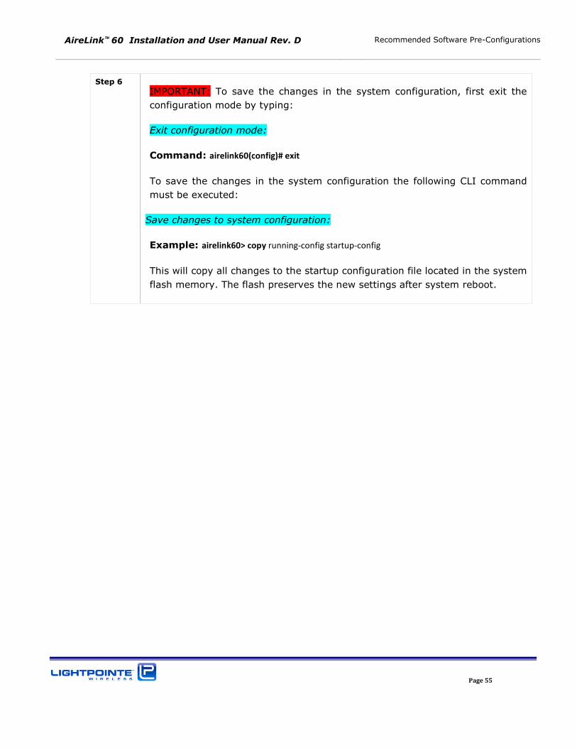
Step 6
IMPORTANT: To save the changes in the system configuration, first exit the
configuration mode by typing:
Exit configuration mode:
Command: airelink60(config)# exit
To save the changes in the system configuration the following CLI command
must be executed:
Save changes to system configuration:
Example: airelink60> copy running-config startup-config
This will copy all changes to the startup configuration file located in the system
flash memory. The flash preserves the new settings after system reboot.
AireLink 60 Installation and User Manual Rev. D Recommended Software Pre-Configurations
Page 56
AireLink 60 Installation and User Manual Rev. D System Installation
Page 57
5 SYSTEM INSTALLATION
This Chapter describes the installation processes involved with successfully deploying the LightPointe
AireLink™ 60 system. Please read carefully and be certain to understand the necessary steps in
deploying a high availability point-to-point wireless link. Contact LightPointe customer support if any
clarification is needed.
5.1 TOOLS
Although the installation of the AireLink™ 60 system requires only a 13 mm wrench (open-end or
combination wrench), a 5 Allen wrench and a simple digital voltmeter, please consider having the
following tools and supplies handy when installing the LightPointe AireLink™ 60 system.
Standard electro-mechanical tool kit with pliers, screwdrivers, wire cutters, wire strippers, etc.
Two-way radio or cell phones to communicate when aligning transmission units
Optical fiber connector cleaning kit - if using fiber to the network
Plastic tie wraps to secure flexible conduits, etc.
13 mm open-end or combination wrench (one for each mounting location)
13 mm socket/ratchet wrench (one for each mounting location)
6 mm Allen wrench – when using the optional LightPointe Universal Mount
Whatever tools may be needed for securing the mount to surfaces/platforms
Electrical tape for securing and fastening
Optical light source and fiber power meter to ensure fiber performance from/to transmission
unit
Digital voltmeter to check electrical system connection and measure the receive signal level
(RSSI)
Step or extension ladder, in needed, for access to elevated locations
High quality rope to use for hoisting materials and/or to be used in conjunction with a safety
harness to ensure installer safety
Exterior rated extension cord
Fish tape for pulling cable
AireLink 60 Installation and User Manual Rev. D System Installation
Page 58
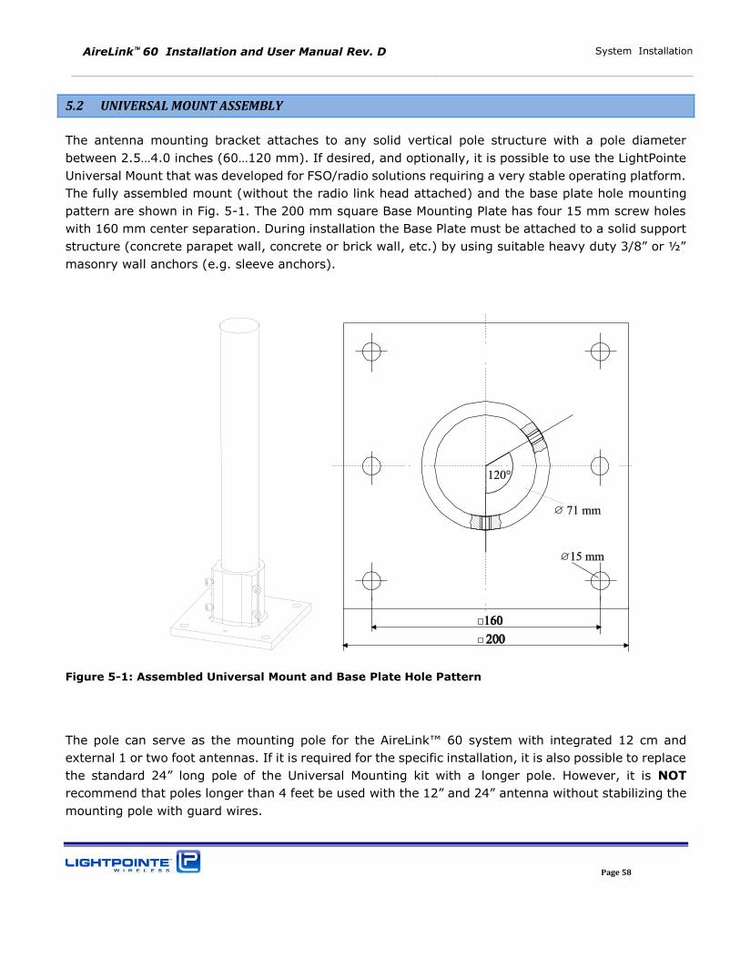
5.2 UNIVERSAL MOUNT ASSEMBLY
The antenna mounting bracket attaches to any solid vertical pole structure with a pole diameter
between 2.5…4.0 inches (60…120 mm). If desired, and optionally, it is possible to use the LightPointe Universal Mount that was developed for FSO/radio solutions requiring a very stable operating platform.
The fully assembled mount (without the radio link head attached) and the base plate hole mounting
pattern are shown in Fig. 5-1. The 200 mm square Base Mounting Plate has four 15 mm screw holes
with 160 mm center separation. During installation the Base Plate must be attached to a solid support
structure (concrete parapet wall, concrete or brick wall, etc.) by using suitable heavy duty 3/8” or ½” masonry wall anchors (e.g. sleeve anchors).
Figure 5-1: Assembled Universal Mount and Base Plate Hole Pattern
The pole can serve as the mounting pole for the AireLink™ 60 system with integrated 12 cm and
external 1 or two foot antennas. If it is required for the specific installation, it is also possible to replace
the standard 24” long pole of the Universal Mounting kit with a longer pole. However, it is NOT
recommend that poles longer than 4 feet be used with the 12” and 24” antenna without stabilizing the
mounting pole with guard wires.
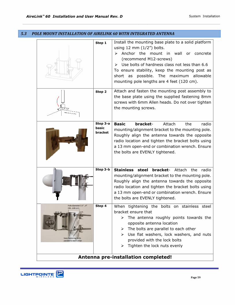
AireLink 60 Installation and User Manual Rev. D System Installation
Page 59
5.3 POLE MOUNT INSTALLATION OF AIRELINK 60 WITH INTEGRATED ANTENNA
Step 1 Install the mounting base plate to a solid platform
using 12 mm (1/2”) bolts. Anchor the mount in wall or concrete
(recommend M12-screws)
Use bolts of hardness class not less than 6.6
To ensure stability, keep the mounting post as
short as possible. The maximum allowable
mounting pole lengths are 4 feet (120 cm).
Step 2 Attach and fasten the mounting post assembly to
the base plate using the supplied fastening 8mm
screws with 6mm Allen heads. Do not over tighten
the mounting screws.
Step 3-a
basic
bracket
Basic bracket- Attach the radio
mounting/alignment bracket to the mounting pole.
Roughly align the antenna towards the opposite
radio location and tighten the bracket bolts using
a 13 mm open-end or combination wrench. Ensure
the bolts are EVENLY tightened.
Step 3-b Stainless steel bracket- Attach the radio
mounting/alignment bracket to the mounting pole.
Roughly align the antenna towards the opposite
radio location and tighten the bracket bolts using
a 13 mm open-end or combination wrench. Ensure
the bolts are EVENLY tightened.
Step 4 When tightening the bolts on stainless steel
bracket ensure that
The antenna roughly points towards the
opposite antenna location
The bolts are parallel to each other
Use flat washers, lock washers, and nuts
provided with the lock bolts
Tighten the lock nuts evenly
Antenna pre-installation completed!
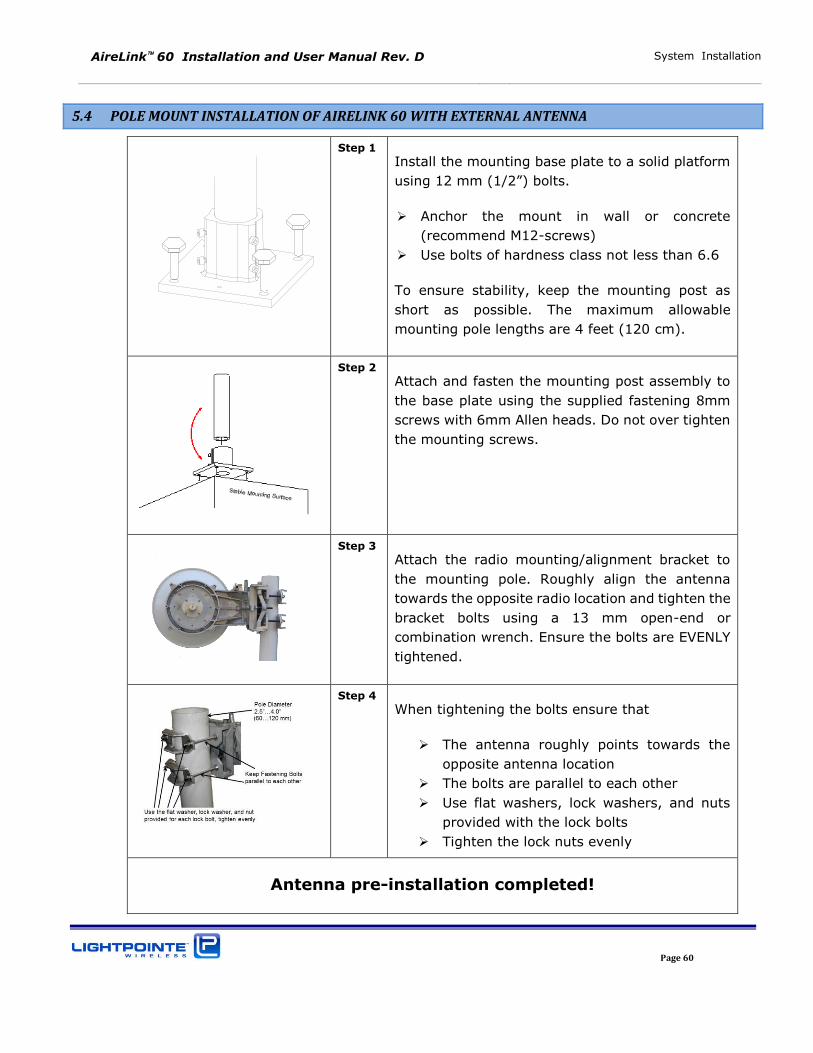
AireLink 60 Installation and User Manual Rev. D System Installation
Page 60
5.4 POLE MOUNT INSTALLATION OF AIRELINK 60 WITH EXTERNAL ANTENNA
Step 1
Install the mounting base plate to a solid platform
using 12 mm (1/2”) bolts.
Anchor the mount in wall or concrete
(recommend M12-screws)
Use bolts of hardness class not less than 6.6
To ensure stability, keep the mounting post as
short as possible. The maximum allowable
mounting pole lengths are 4 feet (120 cm).
Step 2
Attach and fasten the mounting post assembly to
the base plate using the supplied fastening 8mm
screws with 6mm Allen heads. Do not over tighten
the mounting screws.
Step 3
Attach the radio mounting/alignment bracket to
the mounting pole. Roughly align the antenna
towards the opposite radio location and tighten the
bracket bolts using a 13 mm open-end or
combination wrench. Ensure the bolts are EVENLY
tightened.
Step 4
When tightening the bolts ensure that
The antenna roughly points towards the
opposite antenna location
The bolts are parallel to each other
Use flat washers, lock washers, and nuts
provided with the lock bolts
Tighten the lock nuts evenly
Antenna pre-installation completed!
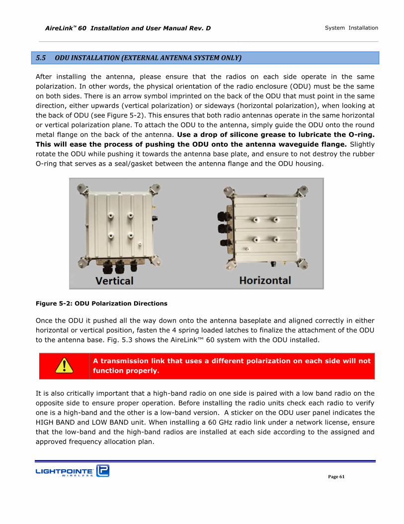
AireLink 60 Installation and User Manual Rev. D System Installation
Page 61
5.5 ODU INSTALLATION (EXTERNAL ANTENNA SYSTEM ONLY)
After installing the antenna, please ensure that the radios on each side operate in the same
polarization. In other words, the physical orientation of the radio enclosure (ODU) must be the same
on both sides. There is an arrow symbol imprinted on the back of the ODU that must point in the same
direction, either upwards (vertical polarization) or sideways (horizontal polarization), when looking at
the back of ODU (see Figure 5-2). This ensures that both radio antennas operate in the same horizontal
or vertical polarization plane. To attach the ODU to the antenna, simply guide the ODU onto the round
metal flange on the back of the antenna. Use a drop of silicone grease to lubricate the O-ring.
This will ease the process of pushing the ODU onto the antenna waveguide flange. Slightly
rotate the ODU while pushing it towards the antenna base plate, and ensure to not destroy the rubber
O-ring that serves as a seal/gasket between the antenna flange and the ODU housing.
Figure 5-2: ODU Polarization Directions
Once the ODU it pushed all the way down onto the antenna baseplate and aligned correctly in either
horizontal or vertical position, fasten the 4 spring loaded latches to finalize the attachment of the ODU
to the antenna base. Fig. 5.3 shows the AireLink™ 60 system with the ODU installed.
A transmission link that uses a different polarization on each side will not
function properly.
It is also critically important that a high-band radio on one side is paired with a low band radio on the
opposite side to ensure proper operation. Before installing the radio units check each radio to verify
one is a high-band and the other is a low-band version. A sticker on the ODU user panel indicates the
HIGH BAND and LOW BAND unit. When installing a 60 GHz radio link under a network license, ensure
that the low-band and the high-band radios are installed at each side according to the assigned and
approved frequency allocation plan.
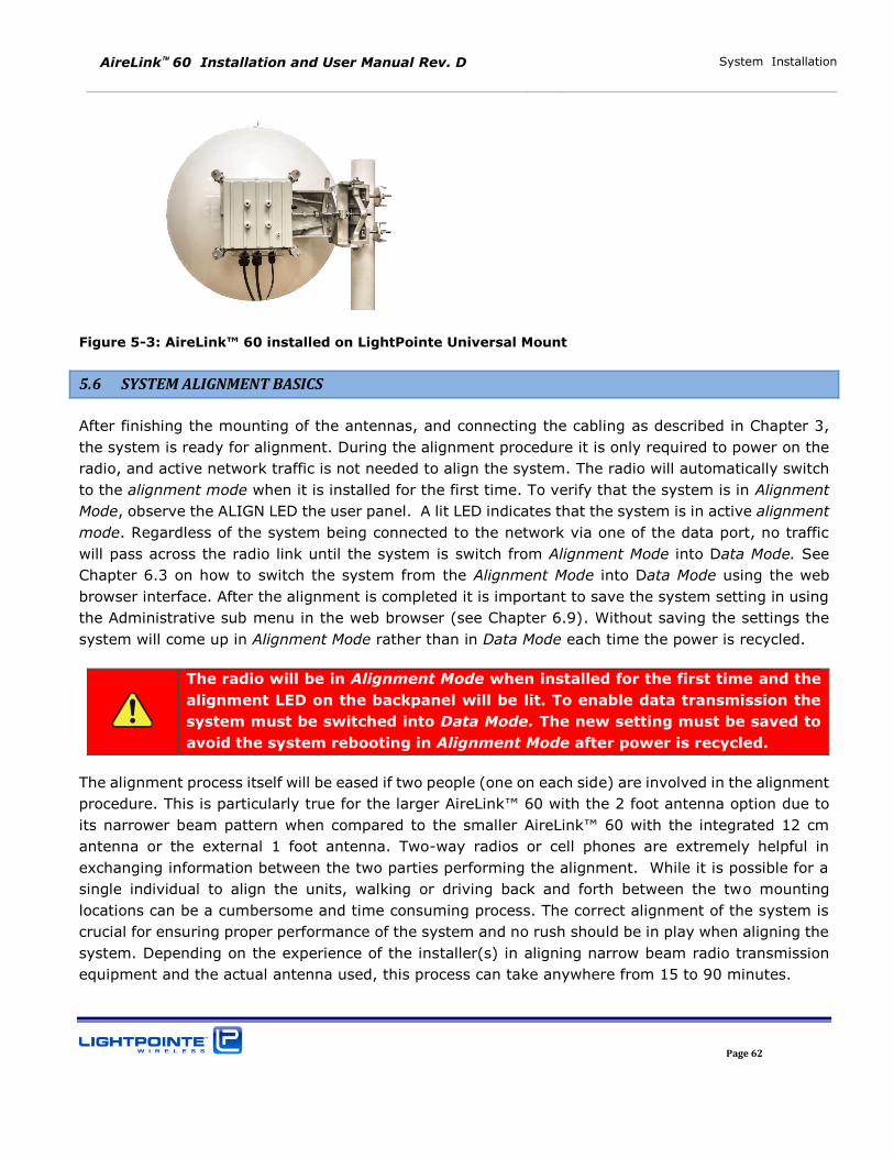
AireLink 60 Installation and User Manual Rev. D System Installation
Page 62
Figure 5-3: AireLink™ 60 installed on LightPointe Universal Mount
5.6 SYSTEM ALIGNMENT BASICS
After finishing the mounting of the antennas, and connecting the cabling as described in Chapter 3,
the system is ready for alignment. During the alignment procedure it is only required to power on the
radio, and active network traffic is not needed to align the system. The radio will automatically switch
to the alignment mode when it is installed for the first time. To verify that the system is in Alignment
Mode, observe the ALIGN LED the user panel. A lit LED indicates that the system is in active alignment
mode. Regardless of the system being connected to the network via one of the data port, no traffic
will pass across the radio link until the system is switch from Alignment Mode into Data Mode. See
Chapter 6.3 on how to switch the system from the Alignment Mode into Data Mode using the web
browser interface. After the alignment is completed it is important to save the system setting in using
the Administrative sub menu in the web browser (see Chapter 6.9). Without saving the settings the
system will come up in Alignment Mode rather than in Data Mode each time the power is recycled.
The radio will be in Alignment Mode when installed for the first time and the
alignment LED on the backpanel will be lit. To enable data transmission the
system must be switched into Data Mode. The new setting must be saved to
avoid the system rebooting in Alignment Mode after power is recycled.
The alignment process itself will be eased if two people (one on each side) are involved in the alignment
procedure. This is particularly true for the larger AireLink™ 60 with the 2 foot antenna option due to
its narrower beam pattern when compared to the smaller AireLink™ 60 with the integrated 12 cm
antenna or the external 1 foot antenna. Two-way radios or cell phones are extremely helpful in
exchanging information between the two parties performing the alignment. While it is possible for a
single individual to align the units, walking or driving back and forth between the two mounting
locations can be a cumbersome and time consuming process. The correct alignment of the system is
crucial for ensuring proper performance of the system and no rush should be in play when aligning the
system. Depending on the experience of the installer(s) in aligning narrow beam radio transmission
equipment and the actual antenna used, this process can take anywhere from 15 to 90 minutes.
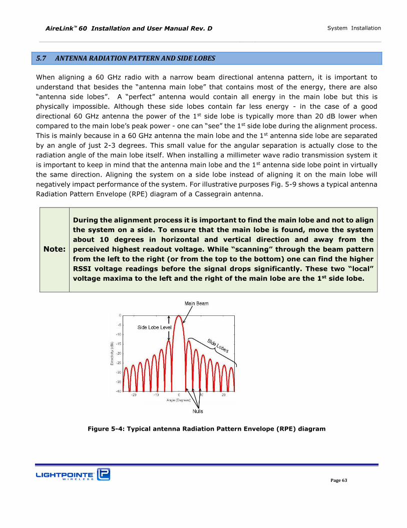
AireLink 60 Installation and User Manual Rev. D System Installation
Page 63
5.7 ANTENNA RADIATION PATTERN AND SIDE LOBES
When aligning a 60 GHz radio with a narrow beam directional antenna pattern, it is important to
understand that besides the “antenna main lobe” that contains most of the energy, there are also “antenna side lobes”. A “perfect” antenna would contain all energy in the main lobe but this is
physically impossible. Although these side lobes contain far less energy - in the case of a good
directional 60 GHz antenna the power of the 1st side lobe is typically more than 20 dB lower when
compared to the main lobe’s peak power - one can “see” the 1st side lobe during the alignment process.
This is mainly because in a 60 GHz antenna the main lobe and the 1st antenna side lobe are separated
by an angle of just 2-3 degrees. This small value for the angular separation is actually close to the
radiation angle of the main lobe itself. When installing a millimeter wave radio transmission system it
is important to keep in mind that the antenna main lobe and the 1st antenna side lobe point in virtually
the same direction. Aligning the system on a side lobe instead of aligning it on the main lobe will
negatively impact performance of the system. For illustrative purposes Fig. 5-9 shows a typical antenna
Radiation Pattern Envelope (RPE) diagram of a Cassegrain antenna.
Note:
During the alignment process it is important to find the main lobe and not to align
the system on a side. To ensure that the main lobe is found, move the system
about 10 degrees in horizontal and vertical direction and away from the
perceived highest readout voltage. While “scanning” through the beam pattern from the left to the right (or from the top to the bottom) one can find the higher
RSSI voltage readings before the signal drops significantly. These two “local” voltage maxima to the left and the right of the main lobe are the 1st side lobe.
Figure 5-4: Typical antenna Radiation Pattern Envelope (RPE) diagram
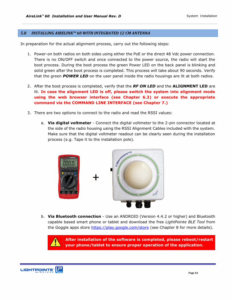
AireLink 60 Installation and User Manual Rev. D System Installation
Page 64
5.8 INSTALLING AIRELINK™ 60 WITH INTEGRATED 12 CM ANTENNA
In preparation for the actual alignment process, carry out the following steps:
1. Power-on both radios on both sides using either the PoE or the direct 48 Vdc power connection.
There is no ON/OFF switch and once connected to the power source, the radio will start the
boot process. During the boot process the green Power LED on the back panel is blinking and
solid green after the boot process is completed. This process will take about 90 seconds. Verify
that the green POWER LED on the user panel inside the radio housings are lit at both radios.
2. After the boot process is completed, verify that the RF ON LED and the ALIGNMENT LED are
lit. In case the alignment LED is off, please switch the system into alignment mode
using the web browser interface (see Chapter 6.3) or execute the appropriate
command via the COMMAND LINE INTERFACE (see Chapter 7.)
3. There are two options to connect to the radio and read the RSSI values:
a. Via digital voltmeter - Connect the digital voltmeter to the 2-pin connector located at
the side of the radio housing using the RSSI Alignment Cables included with the system.
Make sure that the digital voltmeter readout can be clearly seen during the installation
process (e.g. Tape it to the installation pole).
b. Via Bluetooth connection - Use an ANDROID (Version 4.4.2 or higher) and Bluetooth
capable based smart phone or tablet and download the free LightPointe BLE Tool from
the Goggle apps store https://play.google.com/store (see Chapter 8 for more details).
After installation of the software is completed, please reboot/restart
your phone/tablet to ensure proper operation of the application.
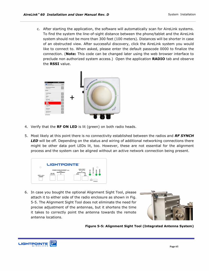
AireLink 60 Installation and User Manual Rev. D System Installation
Page 65
c. After starting the application, the software will automatically scan for AireLink systems.
To find the system the line-of-sight distance between the phone/tablet and the AireLink
system should not be more than 300 feet (100 meters). Distances will be shorter in case
of an obstructed view. After successful discovery, click the AireLink system you would
like to connect to. When asked, please enter the default passcode 0000 to finalize the
connection. (Note: This code can be changed later using the web browser interface to
preclude non authorized system access.) Open the application RADIO tab and observe
the RSSI value.
4. Verify that the RF ON LED is lit (green) on both radio heads.
5. Most likely at this point there is no connectivity established between the radios and RF SYNCH
LED will be off. Depending on the status and wiring of additional networking connections there
might be other data port LEDs lit, too. However, these are not essential for the alignment
process and the system can be aligned without an active network connection being present.
6. In case you bought the optional Alignment Sight Tool, please
attach it to either side of the radio enclosure as shown in Fig.
5-5. The Alignment Sight Tool does not eliminate the need for
precise adjustment of the antennas, but it shortens the time
it takes to correctly point the antenna towards the remote
antenna locations.
Figure 5-5: Alignment Sight Tool (Integrated Antenna System)
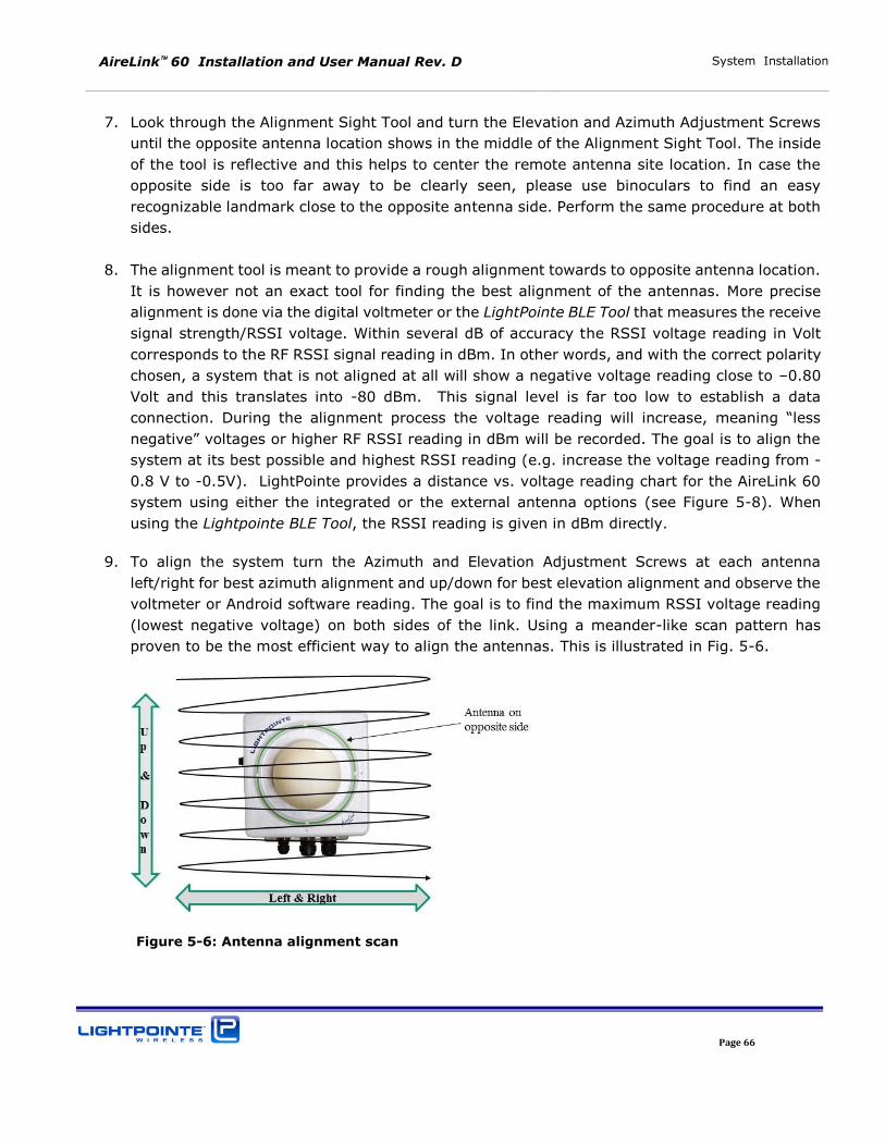
AireLink 60 Installation and User Manual Rev. D System Installation
Page 66
7. Look through the Alignment Sight Tool and turn the Elevation and Azimuth Adjustment Screws
until the opposite antenna location shows in the middle of the Alignment Sight Tool. The inside
of the tool is reflective and this helps to center the remote antenna site location. In case the
opposite side is too far away to be clearly seen, please use binoculars to find an easy
recognizable landmark close to the opposite antenna side. Perform the same procedure at both
sides.
8. The alignment tool is meant to provide a rough alignment towards to opposite antenna location.
It is however not an exact tool for finding the best alignment of the antennas. More precise
alignment is done via the digital voltmeter or the LightPointe BLE Tool that measures the receive
signal strength/RSSI voltage. Within several dB of accuracy the RSSI voltage reading in Volt
corresponds to the RF RSSI signal reading in dBm. In other words, and with the correct polarity
chosen, a system that is not aligned at all will show a negative voltage reading close to –0.80
Volt and this translates into -80 dBm. This signal level is far too low to establish a data
connection. During the alignment process the voltage reading will increase, meaning “less negative” voltages or higher RF RSSI reading in dBm will be recorded. The goal is to align the system at its best possible and highest RSSI reading (e.g. increase the voltage reading from -
0.8 V to -0.5V). LightPointe provides a distance vs. voltage reading chart for the AireLink 60
system using either the integrated or the external antenna options (see Figure 5-8). When
using the Lightpointe BLE Tool, the RSSI reading is given in dBm directly.
9. To align the system turn the Azimuth and Elevation Adjustment Screws at each antenna
left/right for best azimuth alignment and up/down for best elevation alignment and observe the
voltmeter or Android software reading. The goal is to find the maximum RSSI voltage reading
(lowest negative voltage) on both sides of the link. Using a meander-like scan pattern has
proven to be the most efficient way to align the antennas. This is illustrated in Fig. 5-6.
Figure 5-6: Antenna alignment scan
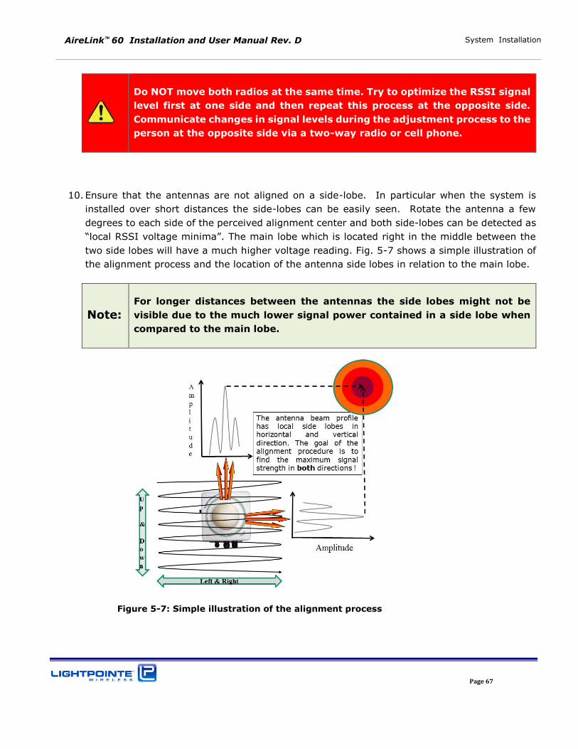
AireLink 60 Installation and User Manual Rev. D System Installation
Page 67
Do NOT move both radios at the same time. Try to optimize the RSSI signal
level first at one side and then repeat this process at the opposite side.
Communicate changes in signal levels during the adjustment process to the
person at the opposite side via a two-way radio or cell phone.
10. Ensure that the antennas are not aligned on a side-lobe. In particular when the system is
installed over short distances the side-lobes can be easily seen. Rotate the antenna a few
degrees to each side of the perceived alignment center and both side-lobes can be detected as
“local RSSI voltage minima”. The main lobe which is located right in the middle between the two side lobes will have a much higher voltage reading. Fig. 5-7 shows a simple illustration of
the alignment process and the location of the antenna side lobes in relation to the main lobe.
Note:
For longer distances between the antennas the side lobes might not be
visible due to the much lower signal power contained in a side lobe when
compared to the main lobe.
Figure 5-7: Simple illustration of the alignment process
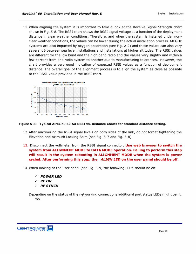
AireLink 60 Installation and User Manual Rev. D System Installation
Page 68
11. When aligning the system it is important to take a look at the Receive Signal Strength chart
shown in Fig. 5-8. The RSSI chart shows the RSSI signal voltage as a function of the deployment
distance in clear weather conditions. Therefore, and when the system is installed under non-
clear weather conditions, the values can be lower during the actual installation process. 60 GHz
systems are also impacted by oxygen absorption (see Fig. 2-2) and these values can also vary
several dB between sea level installations and installations at higher altitudes. The RSSI values
are different for the low band and the high band radio and the values vary slightly and within a
few percent from one radio system to another due to manufacturing tolerances. However, the
chart provides a very good indication of expected RSSI values as a function of deployment
distance. The overall goal of the alignment process is to align the system as close as possible
to the RSSI value provided in the RSSI chart.
Figure 5-8: Typical AireLink 60-SX RSSI vs. Distance Charts for standard distance setting.
12. After maximizing the RSSI signal levels on both sides of the link, do not forget tightening the
Elevation and Azimuth Locking Bolts (see Fig. 5-7 and Fig. 5-8).
13. Disconnect the voltmeter from the RSSI signal connector. Use web browser to switch the
system from ALIGNMENT MODE to DATA MODE operation. Failing to perform this step
will result in the system rebooting in ALIGNMENT MODE when the system is power
cycled. After performing this step, the ALIGN LED on the user panel should be off.
14. When looking at the user panel (see Fig. 5-9) the following LEDs should be on:
POWER LED
RF ON
RF SYNCH
Depending on the status of the networking connections additional port status LEDs might be lit,
too.
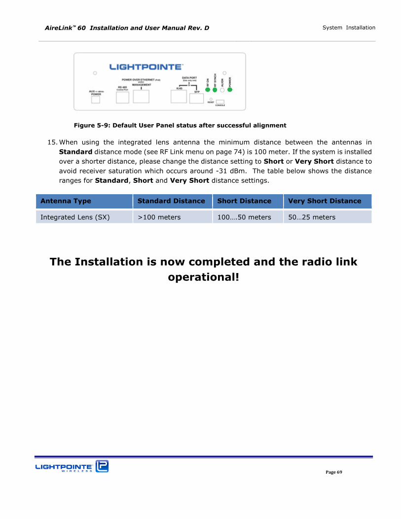
AireLink 60 Installation and User Manual Rev. D System Installation
Page 69
Figure 5-9: Default User Panel status after successful alignment
15. When using the integrated lens antenna the minimum distance between the antennas in
Standard distance mode (see RF Link menu on page 74) is 100 meter. If the system is installed
over a shorter distance, please change the distance setting to Short or Very Short distance to
avoid receiver saturation which occurs around -31 dBm. The table below shows the distance
ranges for Standard, Short and Very Short distance settings.
Antenna Type Standard Distance Short Distance Very Short Distance
Integrated Lens (SX) >100 meters 100….50 meters 50…25 meters
The Installation is now completed and the radio link
operational!
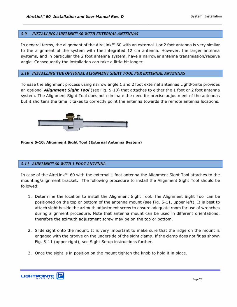
AireLink 60 Installation and User Manual Rev. D System Installation
Page 70
5.9 INSTALLING AIRELINK™ 60 WITH EXTERNAL ANTENNAS
In general terms, the alignment of the AireLink™ 60 with an external 1 or 2 foot antenna is very similar
to the alignment of the system with the integrated 12 cm antenna. However, the larger antenna
systems, and in particular the 2 foot antenna system, have a narrower antenna transmission/receive
angle. Consequently the installation can take a little bit longer.
5.10 INSTALLING THE OPTIONAL ALIGNMENT SIGHT TOOL FOR EXTERNAL ANTENNAS
To ease the alignment process using narrow angle 1 and 2 foot external antennas LightPointe provides
an optional Alignment Sight Tool (see Fig. 5-10) that attaches to either the 1 foot or 2 foot antenna
system. The Alignment Sight Tool does not eliminate the need for precise adjustment of the antennas
but it shortens the time it takes to correctly point the antenna towards the remote antenna locations.
Figure 5-10: Alignment Sight Tool (External Antenna System)
5.11 AIRELINK™ 60 WITH 1 FOOT ANTENNA
In case of the AireLink™ 60 with the external 1 foot antenna the Alignment Sight Tool attaches to the
mounting/alignment bracket. The following procedure to install the Alignment Sight Tool should be
followed:
1. Determine the location to install the Alignment Sight Tool. The Alignment Sight Tool can be
positioned on the top or bottom of the antenna mount (see Fig. 5-11, upper left). It is best to
attach sight beside the azimuth adjustment screw to ensure adequate room for use of wrenches
during alignment procedure. Note that antenna mount can be used in different orientations;
therefore the azimuth adjustment screw may be on the top or bottom.
2. Slide sight onto the mount. It is very important to make sure that the ridge on the mount is
engaged with the groove on the underside of the sight clamp. If the clamp does not fit as shown
Fig. 5-11 (upper right), see Sight Setup instructions further.
3. Once the sight is in position on the mount tighten the knob to hold it in place.
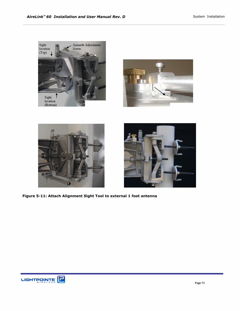
AireLink 60 Installation and User Manual Rev. D System Installation
Page 71
Figure 5-11: Attach Alignment Sight Tool to external 1 foot antenna
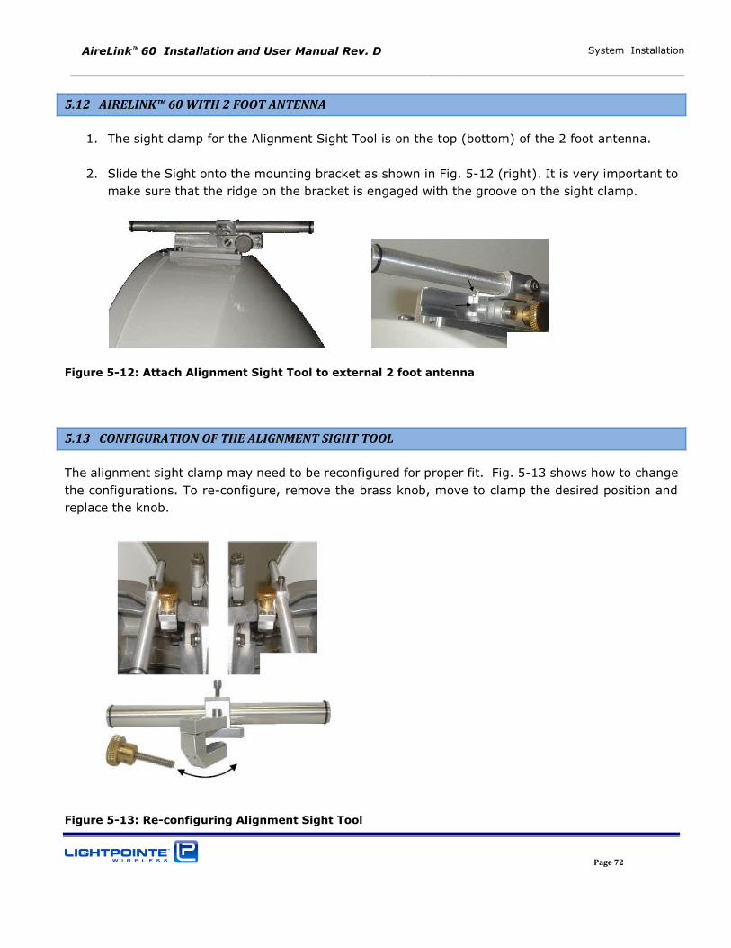
AireLink 60 Installation and User Manual Rev. D System Installation
Page 72
5.12 AIRELINK™ 60 WITH 2 FOOT ANTENNA
1. The sight clamp for the Alignment Sight Tool is on the top (bottom) of the 2 foot antenna.
2. Slide the Sight onto the mounting bracket as shown in Fig. 5-12 (right). It is very important to
make sure that the ridge on the bracket is engaged with the groove on the sight clamp.
Figure 5-12: Attach Alignment Sight Tool to external 2 foot antenna
5.13 CONFIGURATION OF THE ALIGNMENT SIGHT TOOL
The alignment sight clamp may need to be reconfigured for proper fit. Fig. 5-13 shows how to change
the configurations. To re-configure, remove the brass knob, move to clamp the desired position and
replace the knob.
Figure 5-13: Re-configuring Alignment Sight Tool
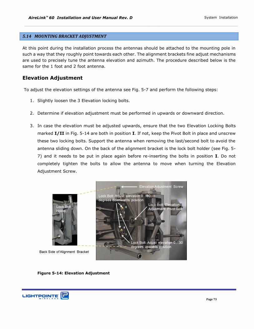
AireLink 60 Installation and User Manual Rev. D System Installation
Page 73
5.14 MOUNTING BRACKET ADJUSTMENT
At this point during the installation process the antennas should be attached to the mounting pole in
such a way that they roughly point towards each other. The alignment brackets fine adjust mechanisms
are used to precisely tune the antenna elevation and azimuth. The procedure described below is the
same for the 1 foot and 2 foot antenna.
Elevation Adjustment
To adjust the elevation settings of the antenna see Fig. 5-7 and perform the following steps:
1. Slightly loosen the 3 Elevation locking bolts.
2. Determine if elevation adjustment must be performed in upwards or downward direction.
3. In case the elevation must be adjusted upwards, ensure that the two Elevation Locking Bolts
marked I/II in Fig. 5-14 are both in position I. If not, keep the Pivot Bolt in place and unscrew
these two locking bolts. Support the antenna when removing the last/second bolt to avoid the
antenna sliding down. On the back of the alignment bracket is the lock bolt holder (see Fig. 5-
7) and it needs to be put in place again before re-inserting the bolts in position I. Do not
completely tighten the bolts to allow the antenna to move when turning the Elevation
Adjustment Screw.
Figure 5-14: Elevation Adjustment
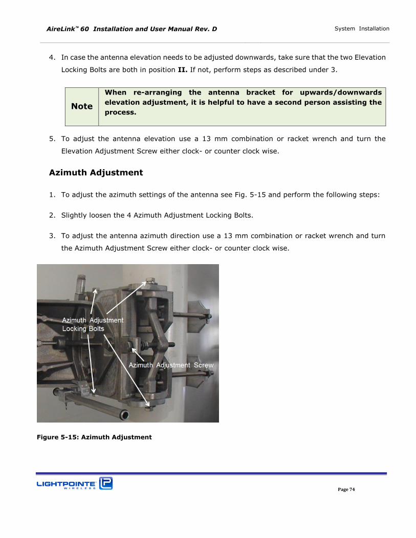
AireLink 60 Installation and User Manual Rev. D System Installation
Page 74
4. In case the antenna elevation needs to be adjusted downwards, take sure that the two Elevation
Locking Bolts are both in position II. If not, perform steps as described under 3.
Note
When re-arranging the antenna bracket for upwards/downwards
elevation adjustment, it is helpful to have a second person assisting the
process.
5. To adjust the antenna elevation use a 13 mm combination or racket wrench and turn the
Elevation Adjustment Screw either clock- or counter clock wise.
Azimuth Adjustment
1. To adjust the azimuth settings of the antenna see Fig. 5-15 and perform the following steps:
2. Slightly loosen the 4 Azimuth Adjustment Locking Bolts.
3. To adjust the antenna azimuth direction use a 13 mm combination or racket wrench and turn
the Azimuth Adjustment Screw either clock- or counter clock wise.
Figure 5-15: Azimuth Adjustment
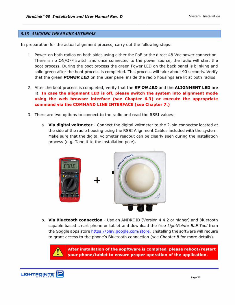
AireLink 60 Installation and User Manual Rev. D System Installation
Page 75
5.15 ALIGNING THE 60 GHZ ANTENNAS
In preparation for the actual alignment process, carry out the following steps:
1. Power-on both radios on both sides using either the PoE or the direct 48 Vdc power connection.
There is no ON/OFF switch and once connected to the power source, the radio will start the
boot process. During the boot process the green Power LED on the back panel is blinking and
solid green after the boot process is completed. This process will take about 90 seconds. Verify
that the green POWER LED on the user panel inside the radio housings are lit at both radios.
2. After the boot process is completed, verify that the RF ON LED and the ALIGNMENT LED are
lit. In case the alignment LED is off, please switch the system into alignment mode
using the web browser interface (see Chapter 6.3) or execute the appropriate
command via the COMMAND LINE INTERFACE (see Chapter 7.)
3. There are two options to connect to the radio and read the RSSI values:
a. Via digital voltmeter - Connect the digital voltmeter to the 2-pin connector located at
the side of the radio housing using the RSSI Alignment Cables included with the system.
Make sure that the digital voltmeter readout can be clearly seen during the installation
process (e.g. Tape it to the installation pole).
b. Via Bluetooth connection - Use an ANDROID (Version 4.4.2 or higher) and Bluetooth
capable based smart phone or tablet and download the free LightPointe BLE Tool from
the Goggle apps store https://play.google.com/store. Installing the software will require
to grant access to the phone’s Bluetooth connection (see Chapter 8 for more details).
After installation of the sopftware is complted, please reboot/restart
your phone/tablet to ensure proper operation of the application.
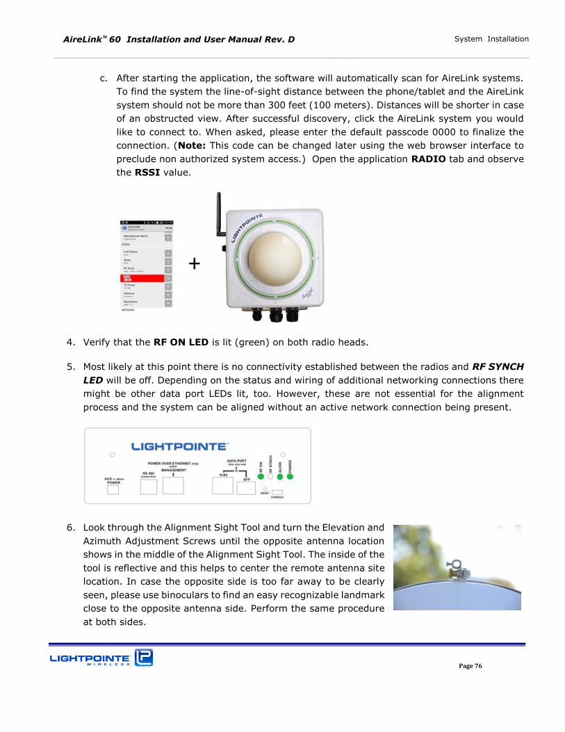
AireLink 60 Installation and User Manual Rev. D System Installation
Page 76
c. After starting the application, the software will automatically scan for AireLink systems.
To find the system the line-of-sight distance between the phone/tablet and the AireLink
system should not be more than 300 feet (100 meters). Distances will be shorter in case
of an obstructed view. After successful discovery, click the AireLink system you would
like to connect to. When asked, please enter the default passcode 0000 to finalize the
connection. (Note: This code can be changed later using the web browser interface to
preclude non authorized system access.) Open the application RADIO tab and observe
the RSSI value.
4. Verify that the RF ON LED is lit (green) on both radio heads.
5. Most likely at this point there is no connectivity established between the radios and RF SYNCH
LED will be off. Depending on the status and wiring of additional networking connections there
might be other data port LEDs lit, too. However, these are not essential for the alignment
process and the system can be aligned without an active network connection being present.
6. Look through the Alignment Sight Tool and turn the Elevation and
Azimuth Adjustment Screws until the opposite antenna location
shows in the middle of the Alignment Sight Tool. The inside of the
tool is reflective and this helps to center the remote antenna site
location. In case the opposite side is too far away to be clearly
seen, please use binoculars to find an easy recognizable landmark
close to the opposite antenna side. Perform the same procedure
at both sides.
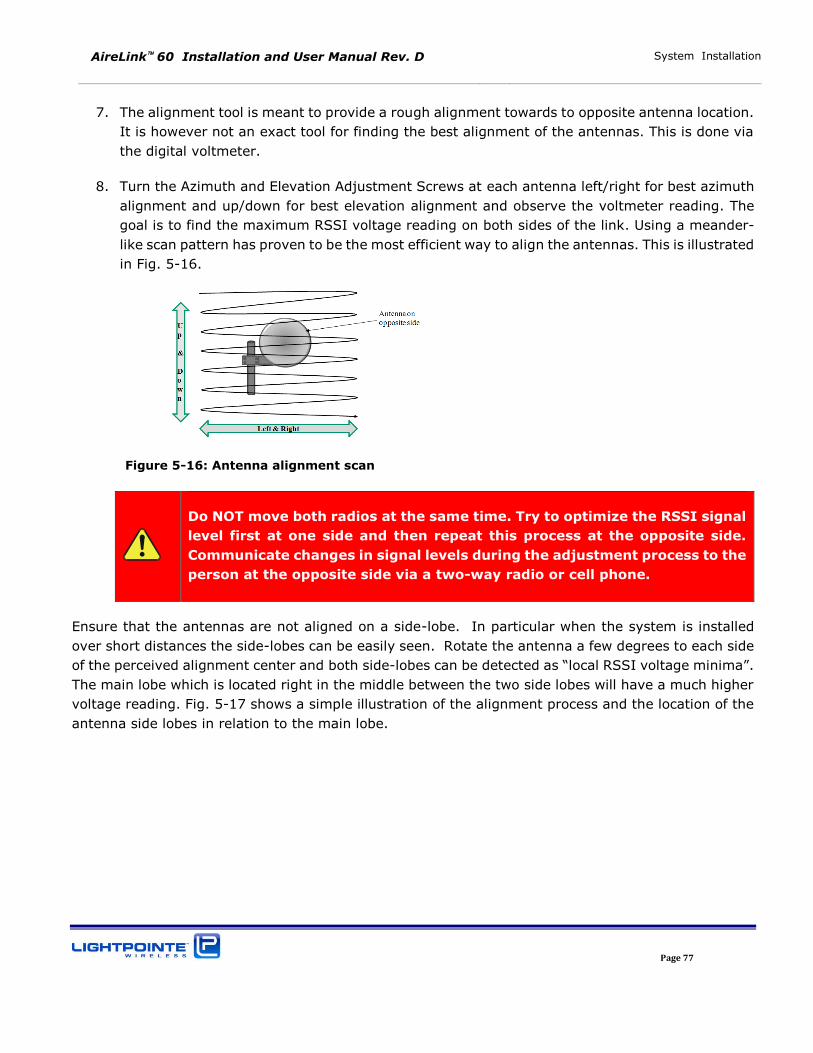
AireLink 60 Installation and User Manual Rev. D System Installation
Page 77
7. The alignment tool is meant to provide a rough alignment towards to opposite antenna location.
It is however not an exact tool for finding the best alignment of the antennas. This is done via
the digital voltmeter.
8. Turn the Azimuth and Elevation Adjustment Screws at each antenna left/right for best azimuth
alignment and up/down for best elevation alignment and observe the voltmeter reading. The
goal is to find the maximum RSSI voltage reading on both sides of the link. Using a meander-
like scan pattern has proven to be the most efficient way to align the antennas. This is illustrated
in Fig. 5-16.
Figure 5-16: Antenna alignment scan
Do NOT move both radios at the same time. Try to optimize the RSSI signal
level first at one side and then repeat this process at the opposite side.
Communicate changes in signal levels during the adjustment process to the
person at the opposite side via a two-way radio or cell phone.
Ensure that the antennas are not aligned on a side-lobe. In particular when the system is installed
over short distances the side-lobes can be easily seen. Rotate the antenna a few degrees to each side
of the perceived alignment center and both side-lobes can be detected as “local RSSI voltage minima”. The main lobe which is located right in the middle between the two side lobes will have a much higher
voltage reading. Fig. 5-17 shows a simple illustration of the alignment process and the location of the
antenna side lobes in relation to the main lobe.
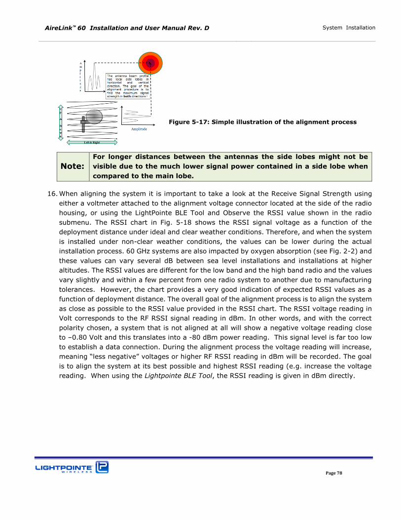
AireLink 60 Installation and User Manual Rev. D System Installation
Page 78
Figure 5-17: Simple illustration of the alignment process
Note:
For longer distances between the antennas the side lobes might not be
visible due to the much lower signal power contained in a side lobe when
compared to the main lobe.
16. When aligning the system it is important to take a look at the Receive Signal Strength using
either a voltmeter attached to the alignment voltage connector located at the side of the radio
housing, or using the LightPointe BLE Tool and Observe the RSSI value shown in the radio
submenu. The RSSI chart in Fig. 5-18 shows the RSSI signal voltage as a function of the
deployment distance under ideal and clear weather conditions. Therefore, and when the system
is installed under non-clear weather conditions, the values can be lower during the actual
installation process. 60 GHz systems are also impacted by oxygen absorption (see Fig. 2-2) and
these values can vary several dB between sea level installations and installations at higher
altitudes. The RSSI values are different for the low band and the high band radio and the values
vary slightly and within a few percent from one radio system to another due to manufacturing
tolerances. However, the chart provides a very good indication of expected RSSI values as a
function of deployment distance. The overall goal of the alignment process is to align the system
as close as possible to the RSSI value provided in the RSSI chart. The RSSI voltage reading in
Volt corresponds to the RF RSSI signal reading in dBm. In other words, and with the correct
polarity chosen, a system that is not aligned at all will show a negative voltage reading close
to –0.80 Volt and this translates into a -80 dBm power reading. This signal level is far too low
to establish a data connection. During the alignment process the voltage reading will increase,
meaning “less negative” voltages or higher RF RSSI reading in dBm will be recorded. The goal is to align the system at its best possible and highest RSSI reading (e.g. increase the voltage
reading. When using the Lightpointe BLE Tool, the RSSI reading is given in dBm directly.
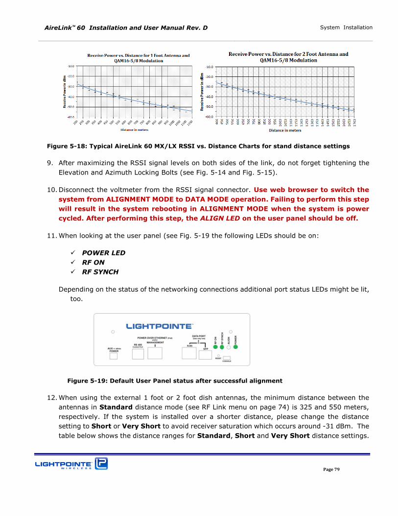
AireLink 60 Installation and User Manual Rev. D System Installation
Page 79
Figure 5-18: Typical AireLink 60 MX/LX RSSI vs. Distance Charts for stand distance settings
9. After maximizing the RSSI signal levels on both sides of the link, do not forget tightening the
Elevation and Azimuth Locking Bolts (see Fig. 5-14 and Fig. 5-15).
10. Disconnect the voltmeter from the RSSI signal connector. Use web browser to switch the
system from ALIGNMENT MODE to DATA MODE operation. Failing to perform this step
will result in the system rebooting in ALIGNMENT MODE when the system is power
cycled. After performing this step, the ALIGN LED on the user panel should be off.
11. When looking at the user panel (see Fig. 5-19 the following LEDs should be on:
POWER LED
RF ON
RF SYNCH
Depending on the status of the networking connections additional port status LEDs might be lit,
too.
Figure 5-19: Default User Panel status after successful alignment
12. When using the external 1 foot or 2 foot dish antennas, the minimum distance between the
antennas in Standard distance mode (see RF Link menu on page 74) is 325 and 550 meters,
respectively. If the system is installed over a shorter distance, please change the distance
setting to Short or Very Short to avoid receiver saturation which occurs around -31 dBm. The
table below shows the distance ranges for Standard, Short and Very Short distance settings.
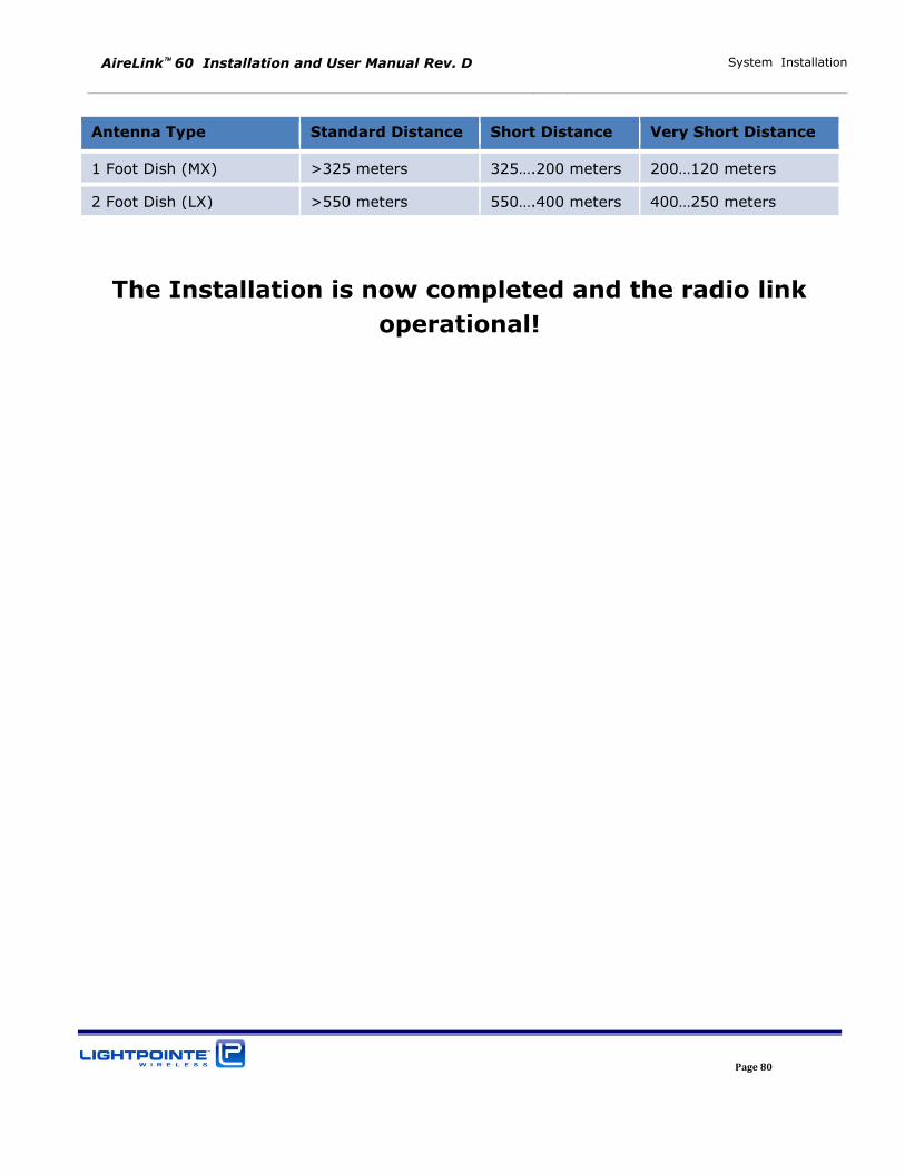
AireLink 60 Installation and User Manual Rev. D System Installation
Page 80
Antenna Type Standard Distance Short Distance Very Short Distance
1 Foot Dish (MX) >325 meters 325….200 meters 200…120 meters
2 Foot Dish (LX) >550 meters 550….400 meters 400…250 meters
The Installation is now completed and the radio link
operational!
AireLink 60 Installation and User Manual Rev. D System Installation
Page 81
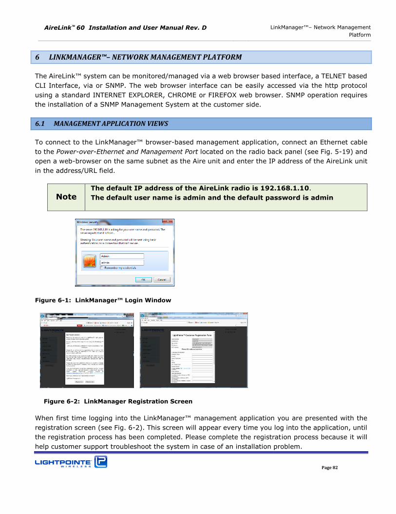
AireLink 60 Installation and User Manual Rev. D LinkManager™– Network Management
Platform
Page 82
6 LINKMANAGER™– NETWORK MANAGEMENT PLATFORM
The AireLink™ system can be monitored/managed via a web browser based interface, a TELNET based
CLI Interface, via or SNMP. The web browser interface can be easily accessed via the http protocol
using a standard INTERNET EXPLORER, CHROME or FIREFOX web browser. SNMP operation requires
the installation of a SNMP Management System at the customer side.
6.1 MANAGEMENT APPLICATION VIEWS
To connect to the LinkManager™ browser-based management application, connect an Ethernet cable
to the Power-over-Ethernet and Management Port located on the radio back panel (see Fig. 5-19) and
open a web-browser on the same subnet as the Aire unit and enter the IP address of the AireLink unit
in the address/URL field.
Note The default IP address of the AireLink radio is 192.168.1.10.
The default user name is admin and the default password is admin
Figure 6-1: LinkManager™ Login Window
Figure 6-2: LinkManager Registration Screen
When first time logging into the LinkManager™ management application you are presented with the
registration screen (see Fig. 6-2). This screen will appear every time you log into the application, until
the registration process has been completed. Please complete the registration process because it will
help customer support troubleshoot the system in case of an installation problem.
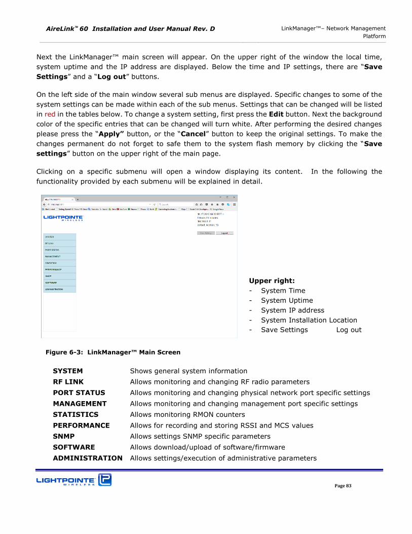
AireLink 60 Installation and User Manual Rev. D LinkManager™– Network Management
Platform
Page 83
Next the LinkManager™ main screen will appear. On the upper right of the window the local time,
system uptime and the IP address are displayed. Below the time and IP settings, there are “Save
Settings” and a “Log out” buttons.
On the left side of the main window several sub menus are displayed. Specific changes to some of the
system settings can be made within each of the sub menus. Settings that can be changed will be listed
in red in the tables below. To change a system setting, first press the Edit button. Next the background
color of the specific entries that can be changed will turn white. After performing the desired changes
please press the “Apply” button, or the “Cancel” button to keep the original settings. To make the
changes permanent do not forget to safe them to the system flash memory by clicking the “Save
settings” button on the upper right of the main page.
Clicking on a specific submenu will open a window displaying its content. In the following the
functionality provided by each submenu will be explained in detail.
Figure 6-3: LinkManager™ Main Screen
SYSTEM Shows general system information
RF LINK Allows monitoring and changing RF radio parameters
PORT STATUS Allows monitoring and changing physical network port specific settings
MANAGEMENT Allows monitoring and changing management port specific settings
STATISTICS Allows monitoring RMON counters
PERFORMANCE Allows for recording and storing RSSI and MCS values
SNMP Allows settings SNMP specific parameters
SOFTWARE Allows download/upload of software/firmware
ADMINISTRATION Allows settings/execution of administrative parameters
Upper right:
- System Time
- System Uptime
- System IP address
- System Installation Location
- Save Settings Log out
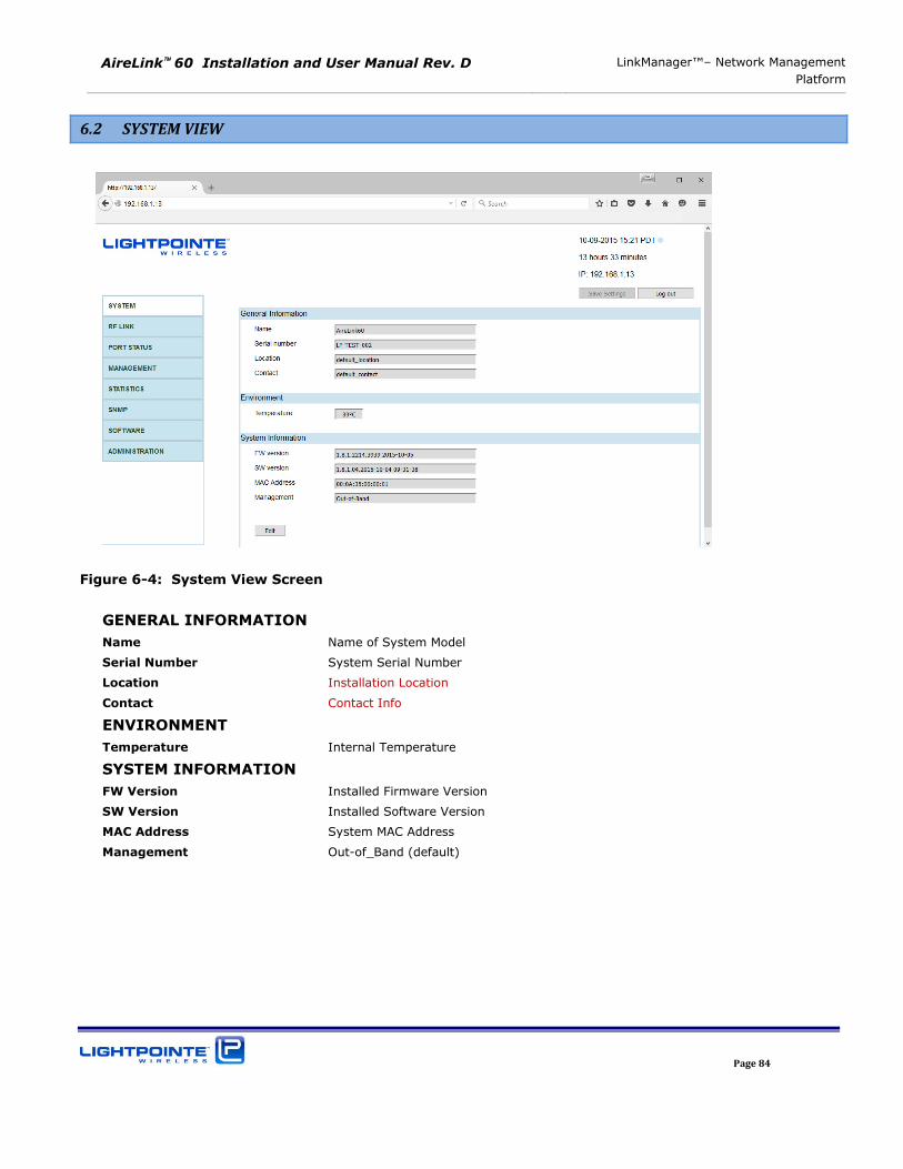
AireLink 60 Installation and User Manual Rev. D LinkManager™– Network Management
Platform
Page 84
6.2 SYSTEM VIEW
Figure 6-4: System View Screen
GENERAL INFORMATION
Name Name of System Model
Serial Number System Serial Number
Location Installation Location
Contact Contact Info
ENVIRONMENT
Temperature Internal Temperature
SYSTEM INFORMATION
FW Version Installed Firmware Version
SW Version Installed Software Version
MAC Address System MAC Address
Management Out-of_Band (default)
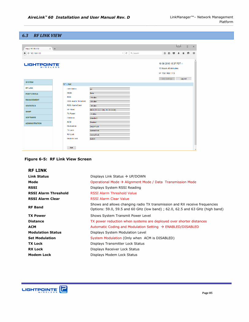
AireLink 60 Installation and User Manual Rev. D LinkManager™– Network Management
Platform
Page 85
6.3 RF LINK VIEW
Figure 6-5: RF Link View Screen
RF LINK
Link Status Displays Link Status UP/DOWN
Mode Operational Mode Alignment Mode / Data Transmission Mode
RSSI Displays System RSSI Reading
RSSI Alarm Threshold RSSI Alarm Threshold Value
RSSI Alarm Clear RSSI Alarm Clear Value
RF Band Shows and allows changing radio TX transmission and RX receive frequencies
Options: 59.0, 59.5 and 60 GHz (low band) ; 62.0, 62.5 and 63 GHz (high band)
TX Power Shows System Transmit Power Level
Distance TX power reduction when systems are deployed over shorter distances
ACM Automatic Coding and Modulation Setting ENABLED/DISABLED
Modulation Status Displays System Modulation Level
Set Modulation System Modulation (Only when ACM is DISABLED)
TX Lock Displays Transmitter Lock Status
RX Lock Displays Receiver Lock Status
Modem Lock Displays Modem Lock Status

AireLink 60 Installation and User Manual Rev. D LinkManager™– Network Management
Platform
Page 86
6.4 PORT STATUS VIEW
The AireLink 60 system has three networking ports:
1. 100/1000 RJ45 copper port
2. GbE Fiber SFP port for SM/MM fiber transceiver
3. 100/1000 RJ45 copper management port (802.3at poE compatible)
Each port can configured separately via the LinkManager™ application.
RJ45 Data Port:
Figure 6-6: Port Status View (RJ45 Data Port)
RJ45 DATA PORT
Link Displays Link Status UP/DOWN
Activity Displays Link Activity Traffic / No Traffic
Enable Port Status ENABLED / DISABLED
Mode Negotiation MANUAL / AUTO-NEGOTIATED
Speed Throughput Configuration 100 Mbps / 1000 Mbps
Duplex Duple Mode HALF / FULL
Flow Control Control Flow ENABLED / DISABLED
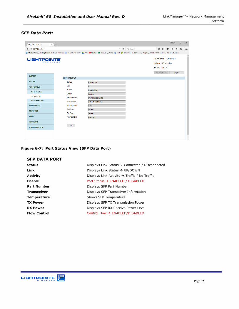
AireLink 60 Installation and User Manual Rev. D LinkManager™– Network Management
Platform
Page 87
SFP Data Port:
Figure 6-7: Port Status View (SFP Data Port)
SFP DATA PORT
Status Displays Link Status Connected / Disconnected
Link Displays Link Status UP/DOWN
Activity Displays Link Activity Traffic / No Traffic
Enable Port Status ENABLED / DISABLED
Part Number Displays SFP Part Number
Transceiver Displays SFP Transceiver Information
Temperature Shows SFP Temperature
TX Power Displays SFP TX Transmission Power
RX Power Displays SFP RX Receive Power Level
Flow Control Control Flow ENABLED/DISABLED
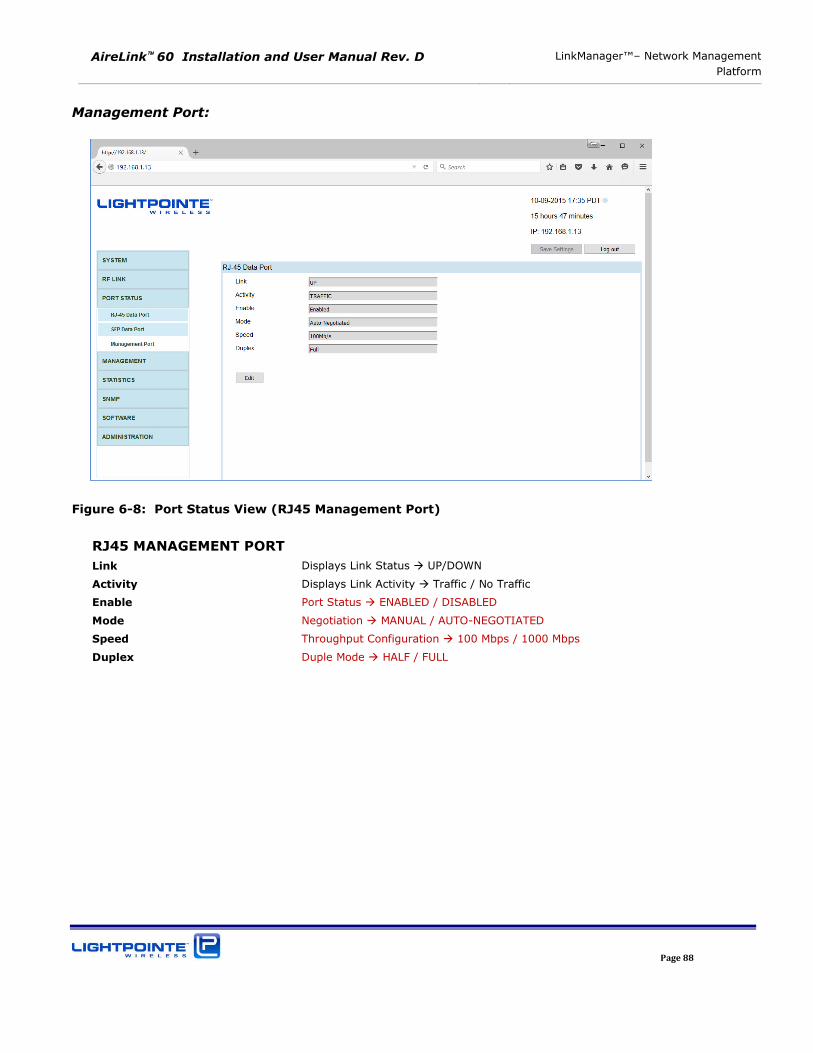
AireLink 60 Installation and User Manual Rev. D LinkManager™– Network Management
Platform
Page 88
Management Port:
Figure 6-8: Port Status View (RJ45 Management Port)
RJ45 MANAGEMENT PORT
Link Displays Link Status UP/DOWN
Activity Displays Link Activity Traffic / No Traffic
Enable Port Status ENABLED / DISABLED
Mode Negotiation MANUAL / AUTO-NEGOTIATED
Speed Throughput Configuration 100 Mbps / 1000 Mbps
Duplex Duple Mode HALF / FULL
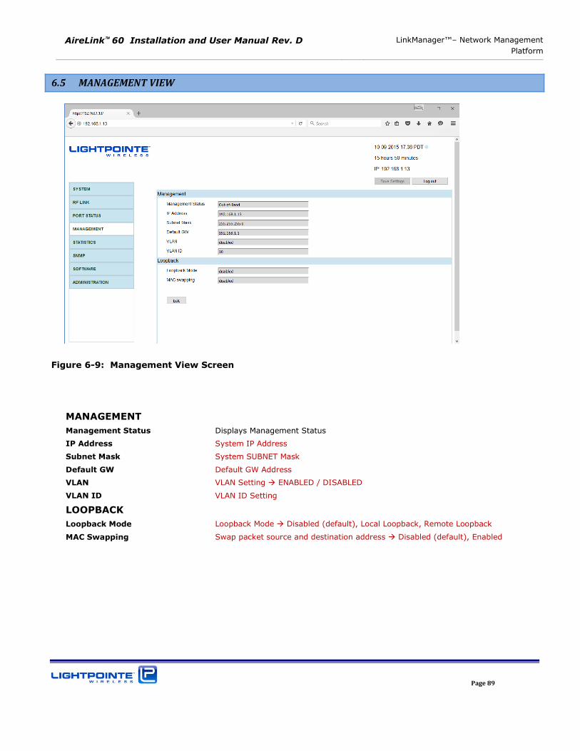
AireLink 60 Installation and User Manual Rev. D LinkManager™– Network Management
Platform
Page 89
6.5 MANAGEMENT VIEW
Figure 6-9: Management View Screen
MANAGEMENT
Management Status Displays Management Status
IP Address System IP Address
Subnet Mask System SUBNET Mask
Default GW Default GW Address
VLAN VLAN Setting ENABLED / DISABLED
VLAN ID VLAN ID Setting
LOOPBACK
Loopback Mode Loopback Mode Disabled (default), Local Loopback, Remote Loopback
MAC Swapping Swap packet source and destination address Disabled (default), Enabled
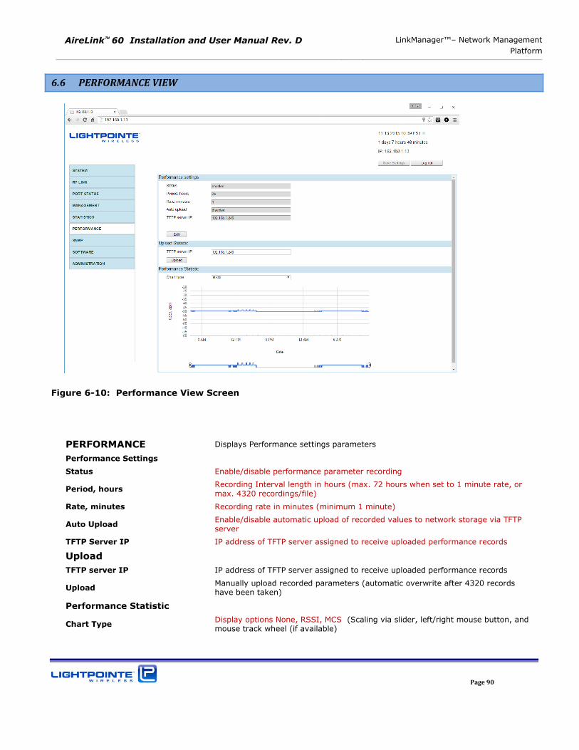
AireLink 60 Installation and User Manual Rev. D LinkManager™– Network Management
Platform
Page 90
6.6 PERFORMANCE VIEW
Figure 6-10: Performance View Screen
PERFORMANCE Displays Performance settings parameters
Performance Settings
Status Enable/disable performance parameter recording
Period, hours Recording Interval length in hours (max. 72 hours when set to 1 minute rate, or max. 4320 recordings/file)
Rate, minutes Recording rate in minutes (minimum 1 minute)
Auto Upload Enable/disable automatic upload of recorded values to network storage via TFTP server
TFTP Server IP IP address of TFTP server assigned to receive uploaded performance records
Upload
TFTP server IP IP address of TFTP server assigned to receive uploaded performance records
Upload Manually upload recorded parameters (automatic overwrite after 4320 records have been taken)
Performance Statistic
Chart Type Display options None, RSSI, MCS (Scaling via slider, left/right mouse button, and mouse track wheel (if available)
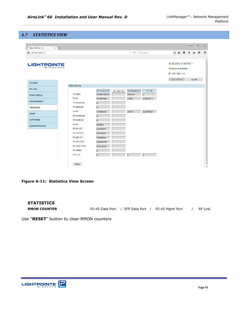
AireLink 60 Installation and User Manual Rev. D LinkManager™– Network Management
Platform
Page 91
6.7 STATISTICS VIEW
Figure 6-11: Statistics View Screen
STATISTICS
RMON COUNTER RJ-45 Data Port / SFP Data Port / RJ-45 Mgmt Port / RF Link
Use “RESET” button to clear RMON counters
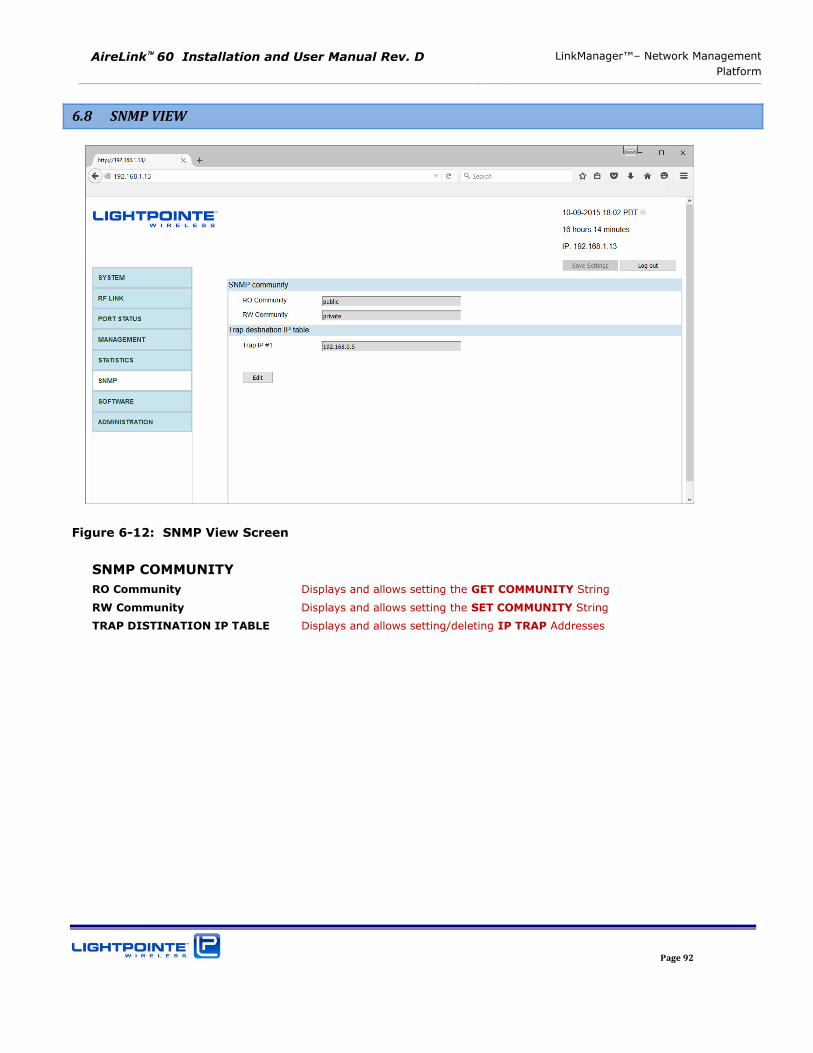
AireLink 60 Installation and User Manual Rev. D LinkManager™– Network Management
Platform
Page 92
6.8 SNMP VIEW
Figure 6-12: SNMP View Screen
SNMP COMMUNITY
RO Community Displays and allows setting the GET COMMUNITY String
RW Community Displays and allows setting the SET COMMUNITY String
TRAP DISTINATION IP TABLE Displays and allows setting/deleting IP TRAP Addresses
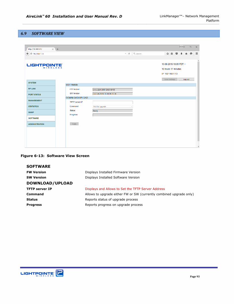
AireLink 60 Installation and User Manual Rev. D LinkManager™– Network Management
Platform
Page 93
6.9 SOFTWARE VIEW
Figure 6-13: Software View Screen
SOFTWARE
FW Version Displays Installed Firmware Version
SW Version Displays Installed Software Version
DOWNLOAD/UPLOAD
TFTP server IP Displays and Allows to Set the TFTP Server Address
Command Allows to upgrade either FW or SW (currently combined upgrade only)
Status Reports status of upgrade process
Progress Reports progress on upgrade process
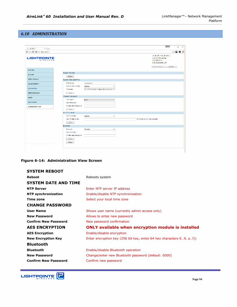
AireLink 60 Installation and User Manual Rev. D LinkManager™– Network Management
Platform
Page 94
6.10 ADMINISTRATION
Figure 6-14: Administration View Screen
SYSTEM REBOOT
Reboot Reboots system
SYSTEM DATE AND TIME
NTP Server Enter NTP server IP address
NTP synchronization Enable/disable NTP synchronization
Time zone Select your local time zone
CHANGE PASSWORD
User Name Shows user name (currently admin access only)
New Password Allows to enter new password
Confirm New Password New password confirmation
AES ENCRYPTION ONLY available when encryption module is installed
AES Encryption Enable/disable encryption
New Encryption Key Enter encryption key (256 bit key, enter 64 hex characters 0…9, a…f))
Bluetooth
Bluetooth Enable/disable Bluetooth operation
New Password Change/enter new Bluetooth password (default: 0000)
Confirm New Password Confirm new password
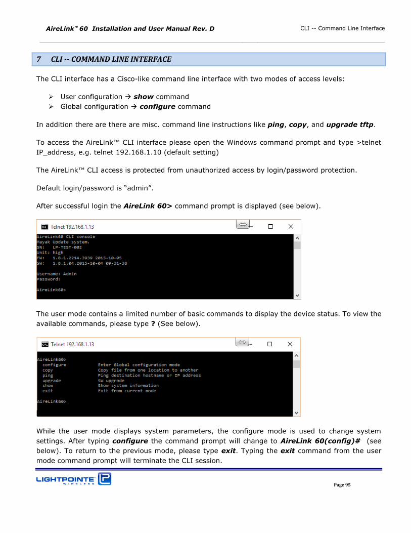
AireLink 60 Installation and User Manual Rev. D CLI -- Command Line Interface
Page 95
7 CLI -- COMMAND LINE INTERFACE
The CLI interface has a Cisco-like command line interface with two modes of access levels:
User configuration show command
Global configuration configure command
In addition there are there are misc. command line instructions like ping, copy, and upgrade tftp.
To access the AireLink™ CLI interface please open the Windows command prompt and type >telnet
IP_address, e.g. telnet 192.168.1.10 (default setting)
The AireLink™ CLI access is protected from unauthorized access by login/password protection.
Default login/password is “admin”.
After successful login the AireLink 60> command prompt is displayed (see below).
The user mode contains a limited number of basic commands to display the device status. To view the
available commands, please type ? (See below).
While the user mode displays system parameters, the configure mode is used to change system
settings. After typing configure the command prompt will change to AireLink 60(config)# (see
below). To return to the previous mode, please type exit. Typing the exit command from the user
mode command prompt will terminate the CLI session.
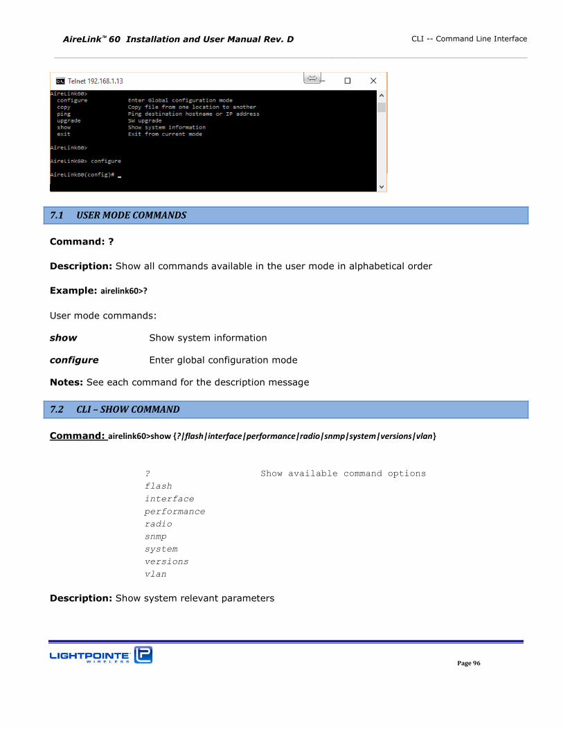
AireLink 60 Installation and User Manual Rev. D CLI -- Command Line Interface
Page 96
7.1 USER MODE COMMANDS
Command: ?
Description: Show all commands available in the user mode in alphabetical order
Example: airelink60>?
User mode commands:
show Show system information
configure Enter global configuration mode
Notes: See each command for the description message
7.2 CLI – SHOW COMMAND
Command: airelink60>show {?|flash|interface|performance|radio|snmp|system|versions|vlan}
? Show available command options
flash
interface
performance
radio
snmp
system
versions
vlan
Description: Show system relevant parameters
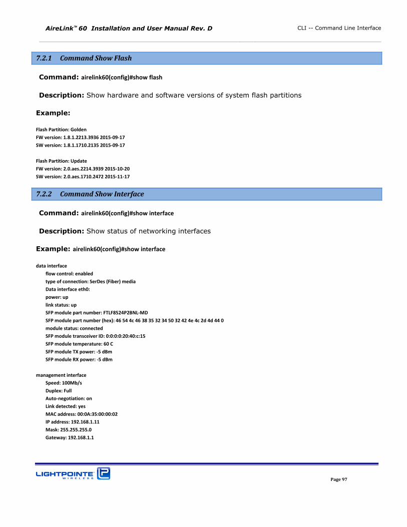
AireLink 60 Installation and User Manual Rev. D CLI -- Command Line Interface
Page 97
7.2.1 Command Show Flash
Command: airelink60(config)#show flash
Description: Show hardware and software versions of system flash partitions
Example:
Flash Partition: Golden
FW version: 1.8.1.2213.3936 2015-09-17
SW version: 1.8.1.1710.2135 2015-09-17
Flash Partition: Update
FW version: 2.0.aes.2214.3939 2015-10-20
SW version: 2.0.aes.1710.2472 2015-11-17
7.2.2 Command Show Interface
Command: airelink60(config)#show interface
Description: Show status of networking interfaces
Example: airelink60(config)#show interface
data interface
flow control: enabled
type of connection: SerDes (Fiber) media
Data interface eth0:
power: up
link status: up
SFP module part number: FTLF8524P2BNL-MD
SFP module part number (hex): 46 54 4c 46 38 35 32 34 50 32 42 4e 4c 2d 4d 44 0
module status: connected
SFP module transceiver ID: 0:0:0:0:20:40:c:15
SFP module temperature: 60 C
SFP module TX power: -5 dBm
SFP module RX power: -5 dBm
management interface
Speed: 100Mb/s
Duplex: Full
Auto-negotiation: on
Link detected: yes
MAC address: 00:0A:35:00:00:02
IP address: 192.168.1.11
Mask: 255.255.255.0
Gateway: 192.168.1.1
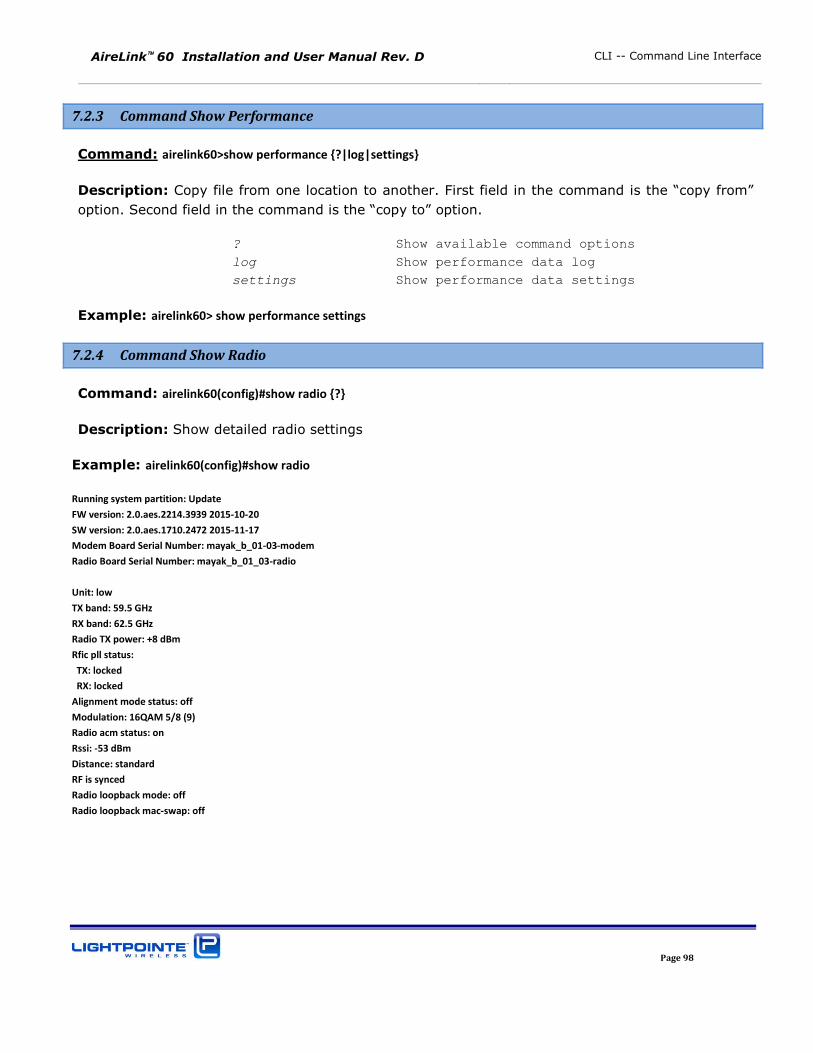
AireLink 60 Installation and User Manual Rev. D CLI -- Command Line Interface
Page 98
7.2.3 Command Show Performance
Command: airelink60>show performance {?|log|settings}
Description: Copy file from one location to another. First field in the command is the “copy from” option. Second field in the command is the “copy to” option.
? Show available command options
log Show performance data log
settings Show performance data settings
Example: airelink60> show performance settings
7.2.4 Command Show Radio
Command: airelink60(config)#show radio {?}
Description: Show detailed radio settings
Example: airelink60(config)#show radio
Running system partition: Update
FW version: 2.0.aes.2214.3939 2015-10-20
SW version: 2.0.aes.1710.2472 2015-11-17
Modem Board Serial Number: mayak_b_01-03-modem
Radio Board Serial Number: mayak_b_01_03-radio
Unit: low
TX band: 59.5 GHz
RX band: 62.5 GHz
Radio TX power: +8 dBm
Rfic pll status:
TX: locked
RX: locked
Alignment mode status: off
Modulation: 16QAM 5/8 (9)
Radio acm status: on
Rssi: -53 dBm
Distance: standard
RF is synced
Radio loopback mode: off
Radio loopback mac-swap: off
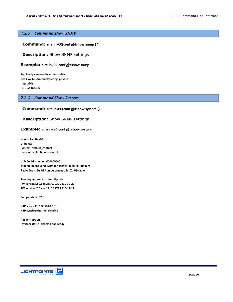
AireLink 60 Installation and User Manual Rev. D CLI -- Command Line Interface
Page 99
7.2.5 Command Show SNMP
Command: airelink60(config)#show snmp {?}
Description: Show SNMP settings
Example: airelink60(config)#show snmp
Read-only community string: public
Read-write community string: private
trap table:
1: 192.168.1.5
7.2.6 Command Show System
Command: airelink60(config)#show system {?}
Description: Show SNMP settings
Example: airelink60(config)#show system
Name: AireLink60
Unit: low
Contact: default_contact
Location: default_location_11
Unit Serial Number: 0000000001
Modem Board Serial Number: mayak_b_01-03-modem
Radio Board Serial Number: mayak_b_01_03-radio
Running system partition: Update
FW version: 2.0.aes.2214.3939 2015-10-20
SW version: 2.0.aes.1710.2472 2015-11-17
Temperature: 52 C
NTP server IP: 132.163.4.101
NTP synchronization: enabled
AES encryption:
system status: enabled and ready
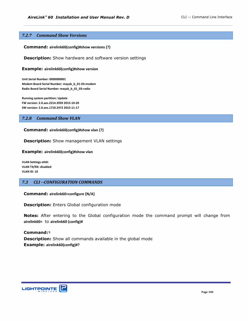
AireLink 60 Installation and User Manual Rev. D CLI -- Command Line Interface
Page 100
7.2.7 Command Show Versions
Command: airelink60(config)#show versions {?}
Description: Show hardware and software version settings
Example: airelink60(config)#show version
Unit Serial Number: 0000000001
Modem Board Serial Number: mayak_b_01-03-modem
Radio Board Serial Number: mayak_b_01_03-radio
Running system partition: Update
FW version: 2.0.aes.2214.3939 2015-10-20
SW version: 2.0.aes.1710.2472 2015-11-17
7.2.8 Command Show VLAN
Command: airelink60(config)#show vlan {?}
Description: Show management VLAN settings
Example: airelink60(config)#show vlan
VLAN Settings eth0:
VLAN TX/RX: disabled
VLAN ID: 10
7.3 CLI --CONFIGURATION COMMANDS
Command: airelink60>configure {N/A}
Description: Enters Global configuration mode
Notes: After entering to the Global configuration mode the command prompt will change from
airelink60> to airelink60 (config)#
Command:?
Description: Show all commands available in the global mode
Example: airelink60(config)#?
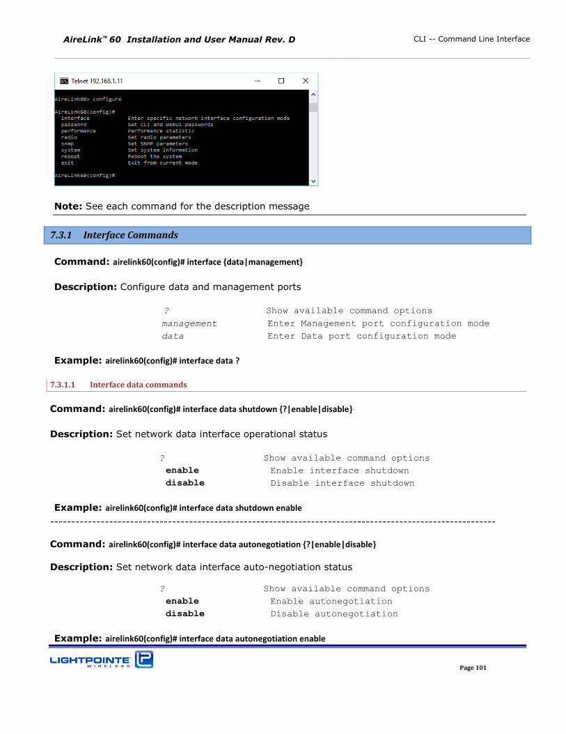
AireLink 60 Installation and User Manual Rev. D CLI -- Command Line Interface
Page 101
Note: See each command for the description message
7.3.1 Interface Commands
Command: airelink60(config)# interface {data|management}
Description: Configure data and management ports
? Show available command options
management Enter Management port configuration mode
data Enter Data port configuration mode
Example: airelink60(config)# interface data ?
7.3.1.1 Interface data commands
Command: airelink60(config)# interface data shutdown {?|enable|disable}
Description: Set network data interface operational status
? Show available command options
enable Enable interface shutdown
disable Disable interface shutdown
Example: airelink60(config)# interface data shutdown enable
----------------------------------------------------------------------------------------------------------
Command: airelink60(config)# interface data autonegotiation {?|enable|disable}
Description: Set network data interface auto-negotiation status
? Show available command options
enable Enable autonegotiation
disable Disable autonegotiation
Example: airelink60(config)# interface data autonegotiation enable
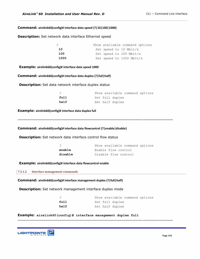
AireLink 60 Installation and User Manual Rev. D CLI -- Command Line Interface
Page 102
Command: airelink60(config)# interface data speed {?|10|100|1000}
Description: Set network data interface Ethernet speed
? Show available command options
10 Set speed to 10 Mbit/s
100 Set speed to 100 Mbit/s
1000 Set speed to 1000 Mbit/s
Example: airelink60(config)# interface data speed 1000
Command: airelink60(config)# interface data duplex {?|full|half}
Description: Set data network interface duplex status
? Show available command options
full Set full duplex
half Set half duplex
Example: airelink60(config)# interface data duplex full
----------------------------------------------------------------------------------------------------------------------------- ------------------------------
Command: airelink60(config)# interface data flowcontrol {?|enable|disable}
Description: Set network data interface control flow status
? Show available command options
enable Enable flow control
disable Disable flow control
Example: airelink60(config)# interface data flowcontrol enable
7.3.1.2 Interface management commands
Command: airelink60(config)# interface management duplex {?|full|half}
Description: Set network management interface duplex mode
? Show available command options
full Set full duplex
half Set half duplex
Example: airelink60(config)# interface management duplex full
----------------------------------------------------------------------------------------------------------------------------- ------------------------------
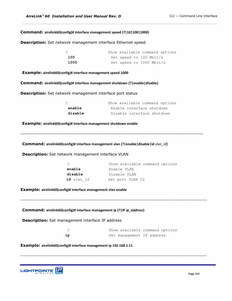
AireLink 60 Installation and User Manual Rev. D CLI -- Command Line Interface
Page 103
Command: airelink60(config)# interface management speed {?|10|100|1000}
Description: Set network management interface Ethernet speed
? Show available command options
100 Set speed to 100 Mbit/s
1000 Set speed to 1000 Mbit/s
Example: airelink60(config)# interface management speed 1000
Command: airelink60(config)# interface management shutdown {?|enable|disable}
Description: Set network management interface port status
? Show available command options
enable Enable interface shutdown
disable Disable interface shutdown
Example: airelink60(config)# interface management shutdown enable
----------------------------------------------------------------------------------------------------------
Command: airelink60(config)# interface management vlan {?|enable|disable|id vlan_id}
Description: Set network management interface VLAN
? Show available command options
enable Enable VLAN
disable Disable VLAN
id vlan_id Set port VLAN ID
Example: airelink60(config)# interface management vlan enable
------------------------------------------------------------------------------------------------------------
Command: airelink60(config)# interface management ip {?|IP ip_address}
Description: Set management interface IP address
? Show available command options
ip Set management IP address
Example: airelink60(config)# interface management ip 192.168.1.11
------------------------------------------------------------------------------------------------------------
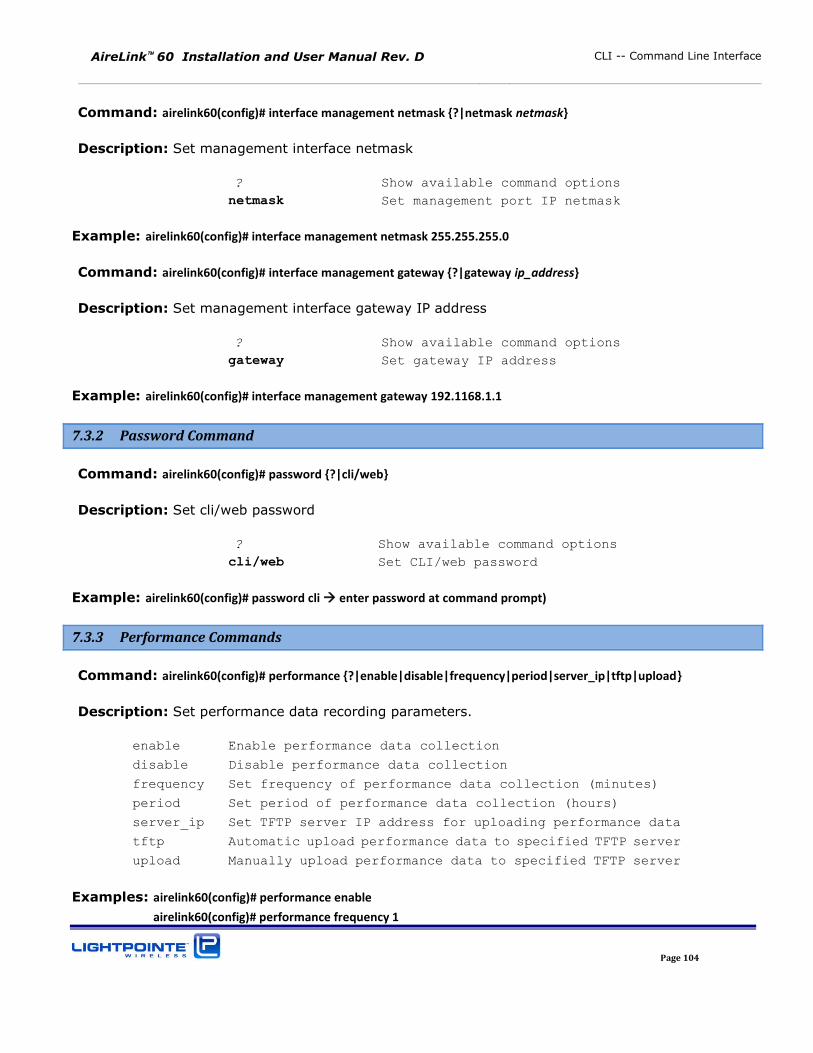
AireLink 60 Installation and User Manual Rev. D CLI -- Command Line Interface
Page 104
Command: airelink60(config)# interface management netmask {?|netmask netmask}
Description: Set management interface netmask
? Show available command options
netmask Set management port IP netmask
Example: airelink60(config)# interface management netmask 255.255.255.0
Command: airelink60(config)# interface management gateway {?|gateway ip_address}
Description: Set management interface gateway IP address
? Show available command options
gateway Set gateway IP address
Example: airelink60(config)# interface management gateway 192.1168.1.1
7.3.2 Password Command
Command: airelink60(config)# password {?|cli/web}
Description: Set cli/web password
? Show available command options
cli/web Set CLI/web password
Example: airelink60(config)# password cli enter password at command prompt)
7.3.3 Performance Commands
Command: airelink60(config)# performance {?|enable|disable|frequency|period|server_ip|tftp|upload}
Description: Set performance data recording parameters.
enable Enable performance data collection
disable Disable performance data collection
frequency Set frequency of performance data collection (minutes)
period Set period of performance data collection (hours)
server_ip Set TFTP server IP address for uploading performance data
tftp Automatic upload performance data to specified TFTP server
upload Manually upload performance data to specified TFTP server
Examples: airelink60(config)# performance enable
airelink60(config)# performance frequency 1
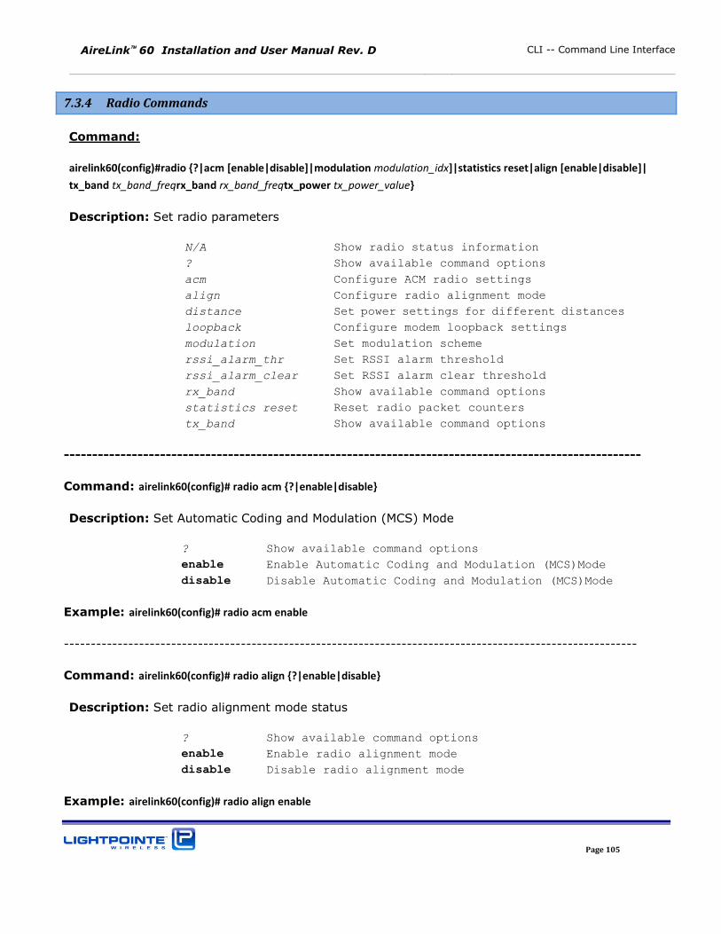
AireLink 60 Installation and User Manual Rev. D CLI -- Command Line Interface
Page 105
7.3.4 Radio Commands
Command:
airelink60(config)#radio {?|acm [enable|disable]|modulation modulation_idx]|statistics reset|align [enable|disable]|
tx_band tx_band_freqrx_band rx_band_freqtx_power tx_power_value}
Description: Set radio parameters
N/A Show radio status information
? Show available command options
acm Configure ACM radio settings
align Configure radio alignment mode
distance Set power settings for different distances
loopback Configure modem loopback settings
modulation Set modulation scheme
rssi_alarm_thr Set RSSI alarm threshold
rssi_alarm_clear Set RSSI alarm clear threshold
rx_band Show available command options
statistics reset Reset radio packet counters
tx_band Show available command options
------------------------------------------------------------------------------------------------------
Command: airelink60(config)# radio acm {?|enable|disable}
Description: Set Automatic Coding and Modulation (MCS) Mode
? Show available command options
enable Enable Automatic Coding and Modulation (MCS)Mode
disable Disable Automatic Coding and Modulation (MCS)Mode
Example: airelink60(config)# radio acm enable
-----------------------------------------------------------------------------------------------------------
Command: airelink60(config)# radio align {?|enable|disable}
Description: Set radio alignment mode status
? Show available command options
enable Enable radio alignment mode
disable Disable radio alignment mode
Example: airelink60(config)# radio align enable
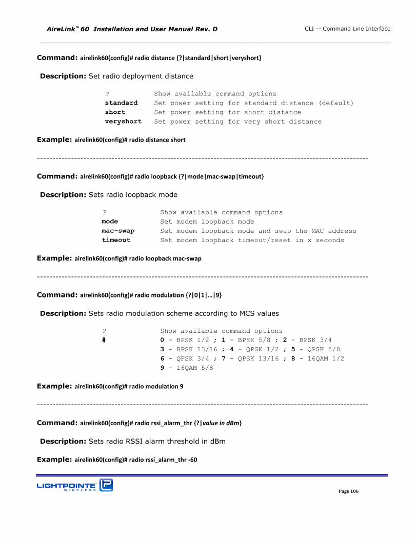
AireLink 60 Installation and User Manual Rev. D CLI -- Command Line Interface
Page 106
Command: airelink60(config)# radio distance {?|standard|short|veryshort}
Description: Set radio deployment distance
? Show available command options
standard Set power setting for standard distance (default)
short Set power setting for short distance
veryshort Set power setting for very short distance
Example: airelink60(config)# radio distance short
-----------------------------------------------------------------------------------------------------------
Command: airelink60(config)# radio loopback {?|mode|mac-swap|timeout}
Description: Sets radio loopback mode
? Show available command options
mode Set modem loopback mode
mac-swap Set modem loopback mode and swap the MAC address
timeout Set modem loopback timeout/reset in x seconds
Example: airelink60(config)# radio loopback mac-swap
-----------------------------------------------------------------------------------------------------------
Command: airelink60(config)# radio modulation {?| | |…|9}
Description: Sets radio modulation scheme according to MCS values
? Show available command options
# 0 - BPSK 1/2 ; 1 - BPSK 5/8 ; 2 - BPSK 3/4
3 - BPSK 13/16 ; 4 – QPSK 1/2 ; 5 - QPSK 5/8 6 - QPSK 3/4 ; 7 - QPSK 13/16 ; 8 - 16QAM 1/2
9 - 16QAM 5/8
Example: airelink60(config)# radio modulation 9
-----------------------------------------------------------------------------------------------------------
Command: airelink60(config)# radio rssi_alarm_thr {?|value in dBm}
Description: Sets radio RSSI alarm threshold in dBm
Example: airelink60(config)# radio rssi_alarm_thr -60
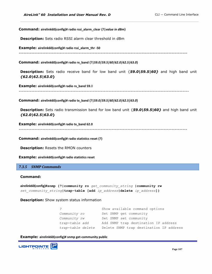
AireLink 60 Installation and User Manual Rev. D CLI -- Command Line Interface
Page 107
Command: airelink60(config)# radio rssi_alarm_clear {?|value in dBm}
Description: Sets radio RSSI alarm clear threshold in dBm
Example: airelink60(config)# radio rssi_alarm_thr -50
-----------------------------------------------------------------------------------------------------------
Command: airelink60(config)# radio rx_band {?|59.0|59.5|60|62.0|62.5|63.0}
Description: Sets radio receive band for low band unit {59.0|59.5|60} and high band unit
{62.0|62.5|63.0}
Example: airelink60(config)# radio rx_band 59.0
------------------------------------------------------------------------------------------------------------
Command: airelink60(config)# radio tx_band {?|59.0|59.5|60|62.0|62.5|63.0}
Description: Sets radio transmission band for low band unit {59.0|59.5|60} and high band unit
{62.0|62.5|63.0}
Example: airelink60(config)# radio tx_band 62.0
-----------------------------------------------------------------------------------------------------------
Command: airelink60(config)# radio statistics reset {?}
Description: Resets the RMON counters
Example: airelink60(config)# radio statistics reset
7.3.5 SNMP Commands
Command:
airelink60(config)#snmp {?|community ro get_community_string |community rw
set_community_string|trap-table [add ip_address|delete ip_address]}
Description: Show system status information
? Show available command options
Community ro Set SNMP get community
Community rw Set SNMP set community
trap-table add Add SNMP trap destination IP address
trap-table delete Delete SNMP trap destination IP address
Example: airelink60(config)# snmp get-community public
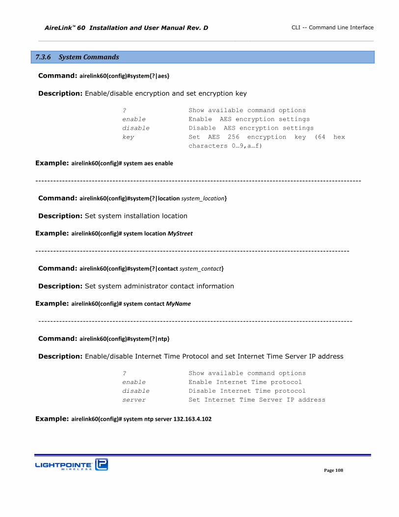
AireLink 60 Installation and User Manual Rev. D CLI -- Command Line Interface
Page 108
7.3.6 System Commands
Command: airelink60(config)#system{?|aes}
Description: Enable/disable encryption and set encryption key
? Show available command options
enable Enable AES encryption settings
disable Disable AES encryption settings
key Set AES 256 encryption key (64 hex
characters 0…9,a…f)
Example: airelink60(config)# system aes enable
--------------------------------------------------------------------------------------------------------------
Command: airelink60(config)#system{?|location system_location}
Description: Set system installation location
Example: airelink60(config)# system location MyStreet
----------------------------------------------------------------------------------------------------------
Command: airelink60(config)#system{?|contact system_contact}
Description: Set system administrator contact information
Example: airelink60(config)# system contact MyName
----------------------------------------------------------------------------------------------------------
Command: airelink60(config)#system{?|ntp}
Description: Enable/disable Internet Time Protocol and set Internet Time Server IP address
? Show available command options
enable Enable Internet Time protocol
disable Disable Internet Time protocol
server Set Internet Time Server IP address
Example: airelink60(config)# system ntp server 132.163.4.102
AireLink 60 Installation and User Manual Rev. D CLI -- Command Line Interface
Page 109
7.3.7 Reboot Command
Command: airelink60(config)# reboot
Description: Executing this command will reboot the system
Example: airelink60(config)# reboot
7.3.8 Exit Command
Command: airelink60(config)# exit
Description: Exit Configuration mode
7.4 CLI -- SAVE SESSION SETTINGS ON FLASH AND SOFTWARE UPGRADE
Command: airelink60>copy {?|running-config|startup-config|flash|tftp}
Description: Copy file from one location to another. First field in the command is the “copy from” option. Second field in the command is the “copy to” option.
? Show available command options
? before the first field shows “Copy from” options
? after the first field shows “Copy to” options
“Copy to/from” options are the same as shown below
running-config Current system configuration
startup-config Startup system configuration
To save the changes in the system configuration that was done during the CLI session the following
CLI command should be executed:
Example: airelink60> copy running-config startup-config
This will copy all the changes to the flash to preserve new settings after the reboot.
AireLink 60 Installation and User Manual Rev. D CLI -- Command Line Interface
Page 110
7.5 CLI -- PING COMMAND
Command: airelink60>ping {hostname|ip_address}
Description: Ping destination hostname or IP address
? Show available command options
hostname Ping destination hostname
ip_address Ping destination IP address
Example: airelink60> ping 192.168.1.115
7.6 CLI – Upgrade TFTP Command
Command: airelink60>upgrade {?|tftp IPserver address|status}
Description: Copy file from one location to another. First field in the command is the “copy from” option. Second field in the command is the “copy to” option.
? Show available command options
tftp IP address Upgrade TFTP server IP address
status Upgrade status
Example: airelink60> upgrade tftp 192.168.1.1
7.7 CLI – LOG COMMAND
Command: airelink60>log {?|tftp IPserver address}
Description:
? Show available command options
tftp IP address Get LOG files from specifiedTFTP
server
Example: airelink60> log tftp 192.168.1.246Basic Management Port Network Setup
The following commands should be used to set management port network parameters. You should be
in the Configuration Mode to set these settings.
AireLink 60 Installation and User Manual Rev. D CLI -- Command Line Interface
Page 111
Set IP address:
Example: airelink60(config)# interface management ip 192.168.1.10
Note: When management port IP address is changed, the new setting will occur immediately. At that
point one will need to connect to the CLI again using new IP address setting.
Set Network Mask address:
Example: airelink60(config)# interface management netmask 255.255.255.0
Set Default Gateway:
Example: airelink60(config)# interface management gateway 192.168.1.1

AireLink 60 Installation and User Manual Rev. D CLI -- Command Line Interface
Page 112
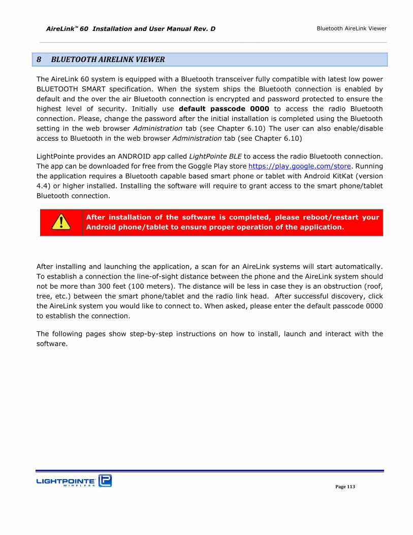
AireLink 60 Installation and User Manual Rev. D Bluetooth AireLink Viewer
Page 113
8 BLUETOOTH AIRELINK VIEWER
The AireLink 60 system is equipped with a Bluetooth transceiver fully compatible with latest low power
BLUETOOTH SMART specification. When the system ships the Bluetooth connection is enabled by
default and the over the air Bluetooth connection is encrypted and password protected to ensure the
highest level of security. Initially use default passcode 0000 to access the radio Bluetooth
connection. Please, change the password after the initial installation is completed using the Bluetooth
setting in the web browser Administration tab (see Chapter 6.10) The user can also enable/disable
access to Bluetooth in the web browser Administration tab (see Chapter 6.10)
LightPointe provides an ANDROID app called LightPointe BLE to access the radio Bluetooth connection.
The app can be downloaded for free from the Goggle Play store https://play.google.com/store. Running
the application requires a Bluetooth capable based smart phone or tablet with Android KitKat (version
4.4) or higher installed. Installing the software will require to grant access to the smart phone/tablet
Bluetooth connection.
After installation of the software is completed, please reboot/restart your
Android phone/tablet to ensure proper operation of the application.
After installing and launching the application, a scan for an AireLink systems will start automatically.
To establish a connection the line-of-sight distance between the phone and the AireLink system should
not be more than 300 feet (100 meters). The distance will be less in case they is an obstruction (roof,
tree, etc.) between the smart phone/tablet and the radio link head. After successful discovery, click
the AireLink system you would like to connect to. When asked, please enter the default passcode 0000
to establish the connection.
The following pages show step-by-step instructions on how to install, launch and interact with the
software.
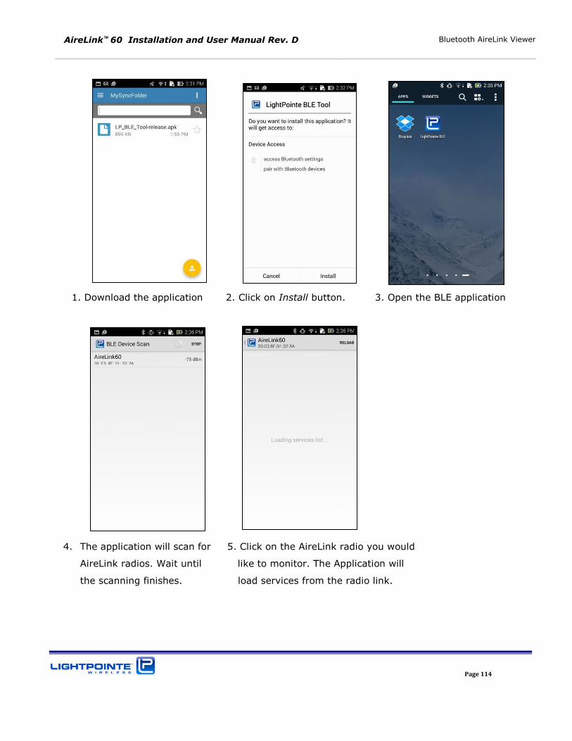
AireLink 60 Installation and User Manual Rev. D Bluetooth AireLink Viewer
Page 114
1. Download the application 2. Click on Install button. 3. Open the BLE application
4. The application will scan for 5. Click on the AireLink radio you would
AireLink radios. Wait until like to monitor. The Application will
the scanning finishes. load services from the radio link.
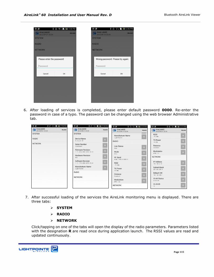
AireLink 60 Installation and User Manual Rev. D Bluetooth AireLink Viewer
Page 115
6. After loading of services is completed, please enter default password 0000. Re-enter the password in case of a typo. The password can be changed using the web browser Administrative tab.
7. After successful loading of the services the AireLink monitoring menu is displayed. There are three tabs:
SYSTEM
RADIO
NETWORK
Click/tapping on one of the tabs will open the display of the radio parameters. Parameters listed with the designation R are read once during application launch. The RSSI values are read and updated continuously.
AireLink 60 Installation and User Manual Rev. D Bluetooth AireLink Viewer
Page 116
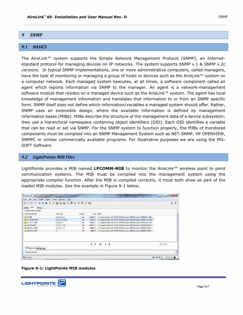
AireLink 60 Installation and User Manual Rev. D SNMP
Page 117
9 SNMP
9.1 BASICS
The AireLink™ system supports the Simple Network Management Protocol (SNMP), an Internet-
standard protocol for managing devices on IP networks. The system supports SNMP v.1 & SNMP v.2c
versions. In typical SNMP implementations, one or more administrative computers, called managers,
have the task of monitoring or managing a group of hosts or devices such as the AireLink™ system on
a computer network. Each managed system executes, at all times, a software component called an
agent which reports information via SNMP to the manager. An agent is a network-management
software module that resides on a managed device such as the AireLink™ system. The agent has local
knowledge of management information and translates that information to or from an SNMP specific
form. SNMP itself does not define which information/variables a managed system should offer. Rather,
SNMP uses an extensible design, where the available information is defined by management
information bases (MIBs). MIBs describe the structure of the management data of a device subsystem;
they use a hierarchical namespace containing object identifiers (OID). Each OID identifies a variable
that can be read or set via SNMP. For the SNMP system to function properly, the MIBs of monitored
components must be compiled into an SNMP Management System such as NET-SNMP, HP OPENVIEW,
SNMPC or similar commercially available programs. For illustrative purposes we are using the MG-
SOFT Software
9.2 LightPointe MIB Files
LightPointe provides a MIB named LPCOMM-MIB to monitor the AireLink™ wireless point to point
communication systems. The MIB must be compiled into the management system using the
appropriate compiler function. After the MIB is compiled correctly, it must both show as part of the
loaded MIB modules. See the example in Figure 9-1 below.
Figure 9-1: LightPointe MIB modules
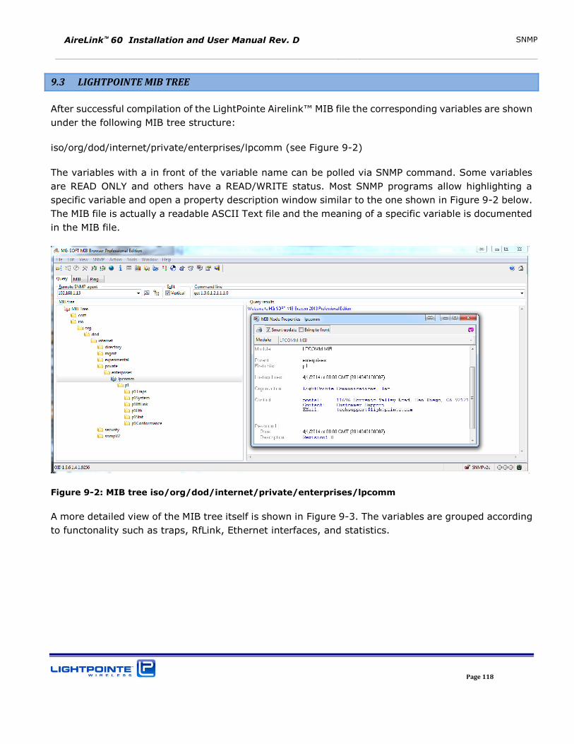
AireLink 60 Installation and User Manual Rev. D SNMP
Page 118
9.3 LIGHTPOINTE MIB TREE
After successful compilation of the LightPointe Airelink™ MIB file the corresponding variables are shown
under the following MIB tree structure:
iso/org/dod/internet/private/enterprises/lpcomm (see Figure 9-2)
The variables with a in front of the variable name can be polled via SNMP command. Some variables
are READ ONLY and others have a READ/WRITE status. Most SNMP programs allow highlighting a
specific variable and open a property description window similar to the one shown in Figure 9-2 below.
The MIB file is actually a readable ASCII Text file and the meaning of a specific variable is documented
in the MIB file.
Figure 9-2: MIB tree iso/org/dod/internet/private/enterprises/lpcomm
A more detailed view of the MIB tree itself is shown in Figure 9-3. The variables are grouped according
to functonality such as traps, RfLink, Ethernet interfaces, and statistics.
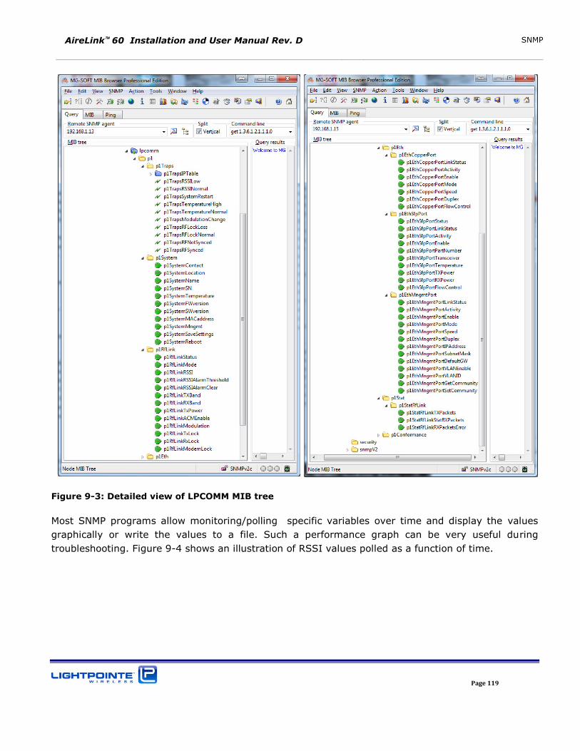
AireLink 60 Installation and User Manual Rev. D SNMP
Page 119
Figure 9-3: Detailed view of LPCOMM MIB tree
Most SNMP programs allow monitoring/polling specific variables over time and display the values
graphically or write the values to a file. Such a performance graph can be very useful during
troubleshooting. Figure 9-4 shows an illustration of RSSI values polled as a function of time.
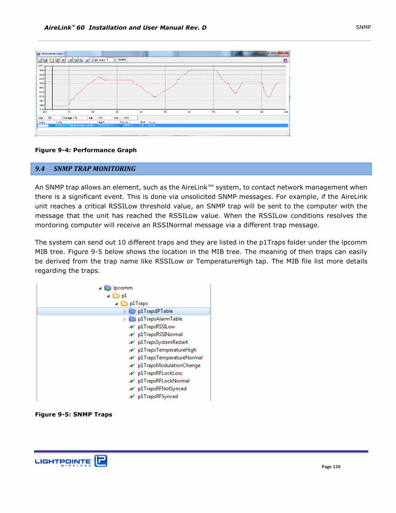
AireLink 60 Installation and User Manual Rev. D SNMP
Page 120
Figure 9-4: Performance Graph
9.4 SNMP TRAP MONITORING
An SNMP trap allows an element, such as the AireLink™ system, to contact network management when
there is a significant event. This is done via unsolicited SNMP messages. For example, if the AireLink
unit reaches a critical RSSILow threshold value, an SNMP trap will be sent to the computer with the
message that the unit has reached the RSSILow value. When the RSSILow conditions resolves the
montoring computer will receive an RSSINormal message via a different trap message.
The system can send out 10 different traps and they are listed in the p1Traps folder under the lpcomm
MIB tree. Figure 9-5 below shows the location in the MIB tree. The meaning of then traps can easily
be derived from the trap name like RSSILow or TemperatureHigh tap. The MIB file list more details
regarding the traps.
Figure 9-5: SNMP Traps
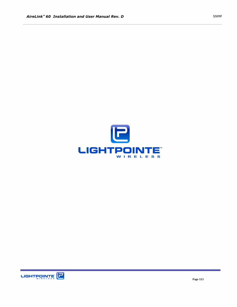
AireLink 60 Installation and User Manual Rev. D SNMP
Page 121
AireLink 60 Installation and User Manual Rev. D Troubleshooting and Diagnostics
Page 122
10 Troubleshooting and Diagnostics
This chapter provides helpful tips on troubleshooting the equipment and covers the following topics:
Types of Failure
Fault isolation troubleshooting charts
Additional troubleshooting methods
The radio units provide a Layer 2 Ethernet connection between remote locations. If the radio units are
correctly aligned and data is transmitted, the problem is usually outside the system.
10.1 FAILURE TYPES
Three different kinds of failures can affect system performance:
Failures caused by attached network components
Failures caused by the environment
System failure of one of the radio units
The use of the AireLink™ Manager program is highly recommended during the troubleshooting process.
Although the AireLink™ Manager is not needed to transmit information through the system, the
program is an essential component in monitoring and managing the AireLink™ 60 system. For details
please refer to Chapter 6 of this manual “LinkManager™ - Network Management Platform”
Troubleshooting Charts
The following troubleshooting charts are meant to guide the user through some simple failure analysis
procedures. Following these procedures will greatly help to ease the troubleshooting process and many
problems can be solved on short notice by the user of the equipment and consequently minimize the
downtime of the system in case of a malfunction. Please use the following charts to locate the problem
before contacting LightPointe or your Reseller.
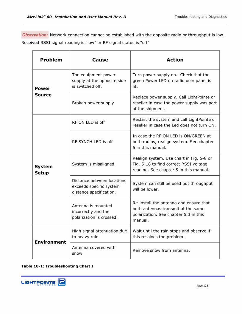
AireLink 60 Installation and User Manual Rev. D Troubleshooting and Diagnostics
Page 123
Observation: Network connection cannot be established with the opposite radio or throughput is low.
Received RSSI signal reading is “low” or RF signal status is “off”
Problem Cause Action
Power
Source
The equipment power
supply at the opposite side
is switched off.
Turn power supply on. Check that the
green Power LED on radio user panel is
lit.
Broken power supply
Replace power supply. Call LightPointe or
reseller in case the power supply was part
of the shipment.
System
Setup
RF ON LED is off Restart the system and call LightPointe or
reseller in case the Led does not turn ON.
RF SYNCH LED is off
In case the RF ON LED is ON/GREEN at
both radios, realign system. See chapter
5 in this manual.
System is misaligned.
Realign system. Use chart in Fig. 5-8 or
Fig. 5-18 to find correct RSSI voltage
reading. See chapter 5 in this manual.
Distance between locations
exceeds specific system
distance specification.
System can still be used but throughput
will be lower.
Antenna is mounted
incorrectly and the
polarization is crossed.
Re-install the antenna and ensure that
both antennas transmit at the same
polarization. See chapter 5.3 in this
manual.
Environment
High signal attenuation due
to heavy rain
Wait until the rain stops and observe if
this resolves the problem.
Antenna covered with
snow. Remove snow from antenna.
Table 10-1: Troubleshooting Chart I
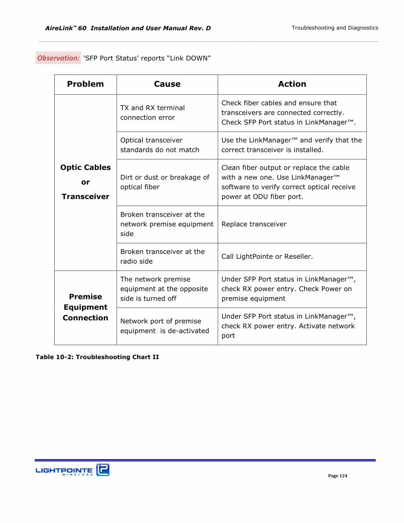
AireLink 60 Installation and User Manual Rev. D Troubleshooting and Diagnostics
Page 124
Observation: ‘SFP Port Status’ reports “Link DOWN”
Problem Cause Action
Optic Cables
or
Transceiver
TX and RX terminal
connection error
Check fiber cables and ensure that
transceivers are connected correctly.
Check SFP Port status in LinkManager™.
Optical transceiver
standards do not match
Use the LinkManager™ and verify that the
correct transceiver is installed.
Dirt or dust or breakage of
optical fiber
Clean fiber output or replace the cable
with a new one. Use LinkManager™
software to verify correct optical receive
power at ODU fiber port.
Broken transceiver at the
network premise equipment
side
Replace transceiver
Broken transceiver at the
radio side Call LightPointe or Reseller.
Premise
Equipment
Connection
The network premise
equipment at the opposite
side is turned off
Under SFP Port status in LinkManager™,
check RX power entry. Check Power on
premise equipment
Network port of premise
equipment is de-activated
Under SFP Port status in LinkManager™,
check RX power entry. Activate network
port
Table 10-2: Troubleshooting Chart II
AireLink 60 Installation and User Manual Rev. D Troubleshooting and Diagnostics
Page 125
AireLink 60 Installation and User Manual Rev. D Advanced Troubleshooting Methods
Page 126
11 Advanced Troubleshooting Methods
11.1 Performing a PING Test
A ping test is not a particularly sophisticated networking test but it does provide the user with an easy
method to check the connectivity of IP based network equipment. When performing a ping test
between two laptops and without other network equipment in the circuit, the ping test provides
valuable information about the performance of the radio transmission link itself. Other tests may
involve additional network equipment and therefore complicate the issue, making it difficult to find the
root cause of a potential problem. The following equipment and software are needed to perform a ping
test:
Two laptops or PCs with Ethernet cards
Two Ethernet cables with RJ45 connectors
Additionally, if performing the test over radio fiber connection:
Two media converters
Depending on SFP transceiver installed in radio units use either multimode 1000Base-SX (850
nm) or 1000Base-LX (1300 nm) media converter. In case of using an older laptop that does
not have a 1250 Mbps RJ45 (Gigabit Ethernet) connection, a 100/1000 switched media
converter will be required.
Four simplex (or two duplex) optical fiber patch cords with correct termination. The radio
transceiver has a LC type connector and the other termination will depend on the termination
of the media converter.
11.2 EQUIPMENT CONNECTION AND NETWORK SETTINGS
To perform a ping test directly connect the two laptops/PCs to the radio link heads using either Cat5E/6
cables or additionally with a media converter on each side, if connecting via fiber. It is important to
know which port of the radio unit is active. For details please refer to the “LinkManager™ - Network
Management Platform” in Chapter 6.. Ensure that the radio units are aligned and that all status
indicators show that the system is physically connected.
Note
This ping test is based on using two computers. It is possible to do a ping test
with just one laptop if the remote radio side is connected to network equipment
(switch/router) with a known IP. However, by doing so it might be difficult to
isolate a potential networking problem and draw a definitive conclusion.
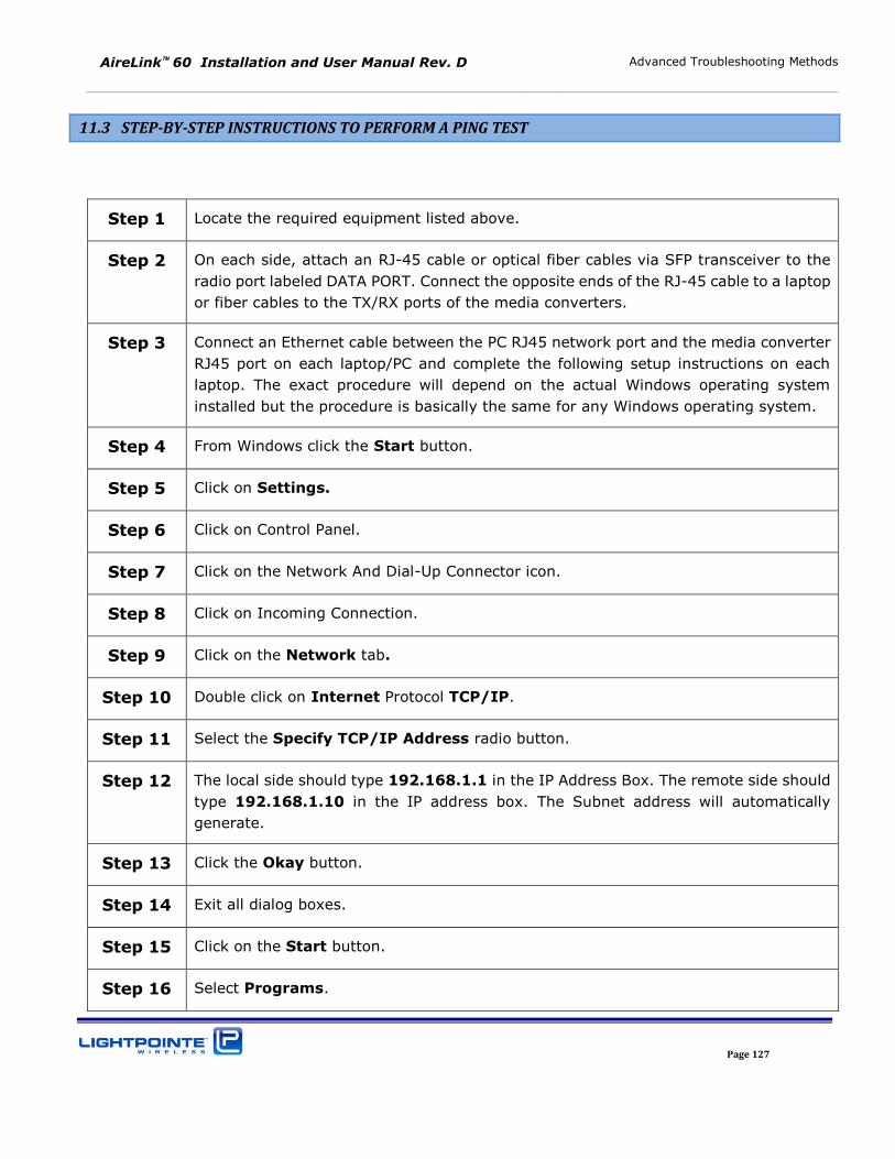
AireLink 60 Installation and User Manual Rev. D Advanced Troubleshooting Methods
Page 127
11.3 STEP-BY-STEP INSTRUCTIONS TO PERFORM A PING TEST
Step 1 Locate the required equipment listed above.
Step 2 On each side, attach an RJ-45 cable or optical fiber cables via SFP transceiver to the
radio port labeled DATA PORT. Connect the opposite ends of the RJ-45 cable to a laptop
or fiber cables to the TX/RX ports of the media converters.
Step 3 Connect an Ethernet cable between the PC RJ45 network port and the media converter
RJ45 port on each laptop/PC and complete the following setup instructions on each
laptop. The exact procedure will depend on the actual Windows operating system
installed but the procedure is basically the same for any Windows operating system.
Step 4 From Windows click the Start button.
Step 5 Click on Settings.
Step 6 Click on Control Panel.
Step 7 Click on the Network And Dial-Up Connector icon.
Step 8 Click on Incoming Connection.
Step 9 Click on the Network tab.
Step 10 Double click on Internet Protocol TCP/IP.
Step 11 Select the Specify TCP/IP Address radio button.
Step 12 The local side should type 192.168.1.1 in the IP Address Box. The remote side should
type 192.168.1.10 in the IP address box. The Subnet address will automatically
generate.
Step 13 Click the Okay button.
Step 14 Exit all dialog boxes.
Step 15 Click on the Start button.
Step 16 Select Programs.
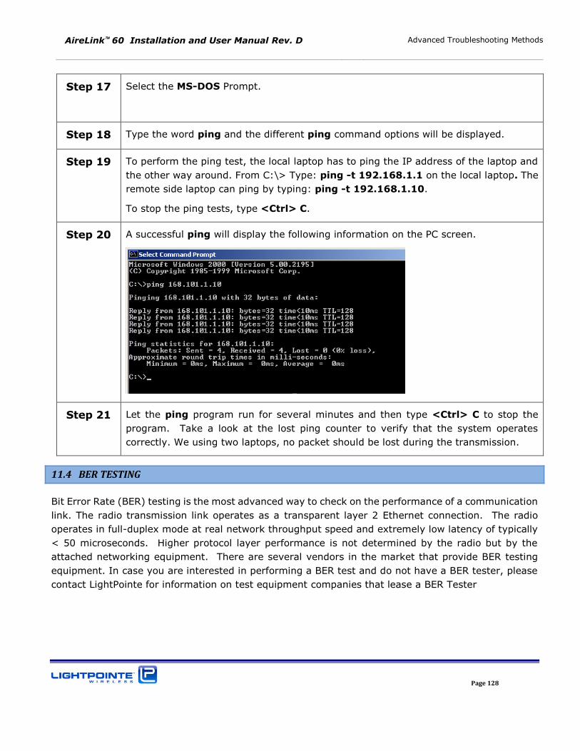
AireLink 60 Installation and User Manual Rev. D Advanced Troubleshooting Methods
Page 128
Step 17
Select the MS-DOS Prompt.
Step 18 Type the word ping and the different ping command options will be displayed.
Step 19 To perform the ping test, the local laptop has to ping the IP address of the laptop and
the other way around. From C:\> Type: ping -t 192.168.1.1 on the local laptop. The
remote side laptop can ping by typing: ping -t 192.168.1.10.
To stop the ping tests, type <Ctrl> C.
Step 20 A successful ping will display the following information on the PC screen.
Step 21 Let the ping program run for several minutes and then type <Ctrl> C to stop the
program. Take a look at the lost ping counter to verify that the system operates
correctly. We using two laptops, no packet should be lost during the transmission.
11.4 BER TESTING
Bit Error Rate (BER) testing is the most advanced way to check on the performance of a communication
link. The radio transmission link operates as a transparent layer 2 Ethernet connection. The radio
operates in full-duplex mode at real network throughput speed and extremely low latency of typically
< 50 microseconds. Higher protocol layer performance is not determined by the radio but by the
attached networking equipment. There are several vendors in the market that provide BER testing
equipment. In case you are interested in performing a BER test and do not have a BER tester, please
contact LightPointe for information on test equipment companies that lease a BER Tester
AireLink 60 Installation and User Manual Rev. D Advanced Troubleshooting Methods
Page 129
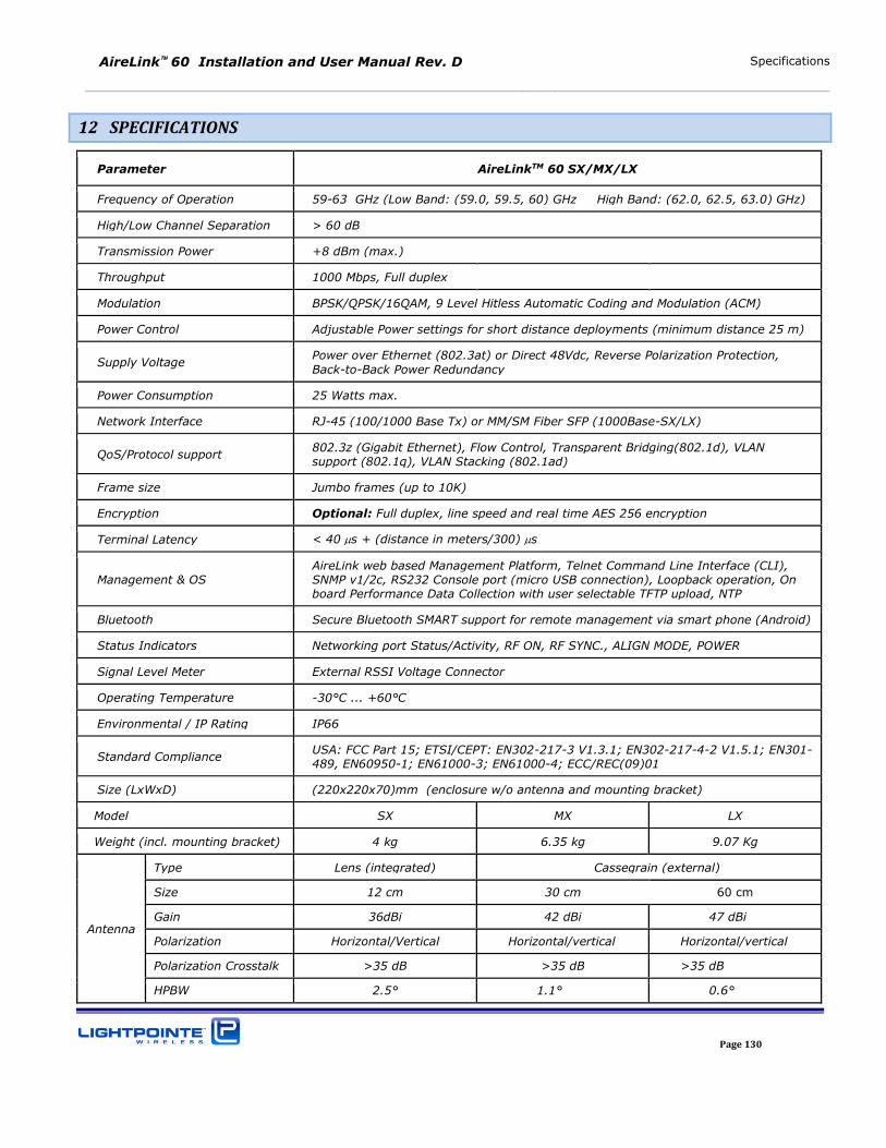
AireLink 60 Installation and User Manual Rev. D Specifications
Page 130
12 SPECIFICATIONS
Parameter AireLinkTM 60 SX/MX/LX
Frequency of Operation 59-63 GHz (Low Band: (59.0, 59.5, 60) GHz High Band: (62.0, 62.5, 63.0) GHz)
High/Low Channel Separation > 60 dB
Transmission Power +8 dBm (max.)
Throughput 1000 Mbps, Full duplex
Modulation BPSK/QPSK/16QAM, 9 Level Hitless Automatic Coding and Modulation (ACM)
Power Control Adjustable Power settings for short distance deployments (minimum distance 25 m)
Supply Voltage Power over Ethernet (802.3at) or Direct 48Vdc, Reverse Polarization Protection,
Back-to-Back Power Redundancy
Power Consumption 25 Watts max.
Network Interface RJ-45 (100/1000 Base Tx) or MM/SM Fiber SFP (1000Base-SX/LX)
QoS/Protocol support 802.3z (Gigabit Ethernet), Flow Control, Transparent Bridging(802.1d), VLAN support (802.1q), VLAN Stacking (802.1ad)
Frame size Jumbo frames (up to 10K)
Encryption Optional: Full duplex, line speed and real time AES 256 encryption
Terminal Latency < 40 s + (distance in meters/300) s
Management & OS AireLink web based Management Platform, Telnet Command Line Interface (CLI), SNMP v1/2c, RS232 Console port (micro USB connection), Loopback operation, On board Performance Data Collection with user selectable TFTP upload, NTP
Bluetooth Secure Bluetooth SMART support for remote management via smart phone (Android)
Status Indicators Networking port Status/Activity, RF ON, RF SYNC., ALIGN MODE, POWER
Signal Level Meter External RSSI Voltage Connector
Operating Temperature -30°C ... +60°C
Environmental / IP Rating IP66
Standard Compliance USA: FCC Part 15; ETSI/CEPT: EN302-217-3 V1.3.1; EN302-217-4-2 V1.5.1; EN301-489, EN60950-1; EN61000-3; EN61000-4; ECC/REC(09)01
Size (LxWxD) (220x220x70)mm (enclosure w/o antenna and mounting bracket)
Model SX MX LX
Weight (incl. mounting bracket) 4 kg 6.35 kg 9.07 Kg
Antenna
Type Lens (integrated) Cassegrain (external)
Size 12 cm 30 cm 60 cm
Gain 36dBi 42 dBi 47 dBi
Polarization Horizontal/Vertical Horizontal/vertical Horizontal/vertical
Polarization Crosstalk >35 dB >35 dB >35 dB
HPBW 2.5° 1.1° 0.6°
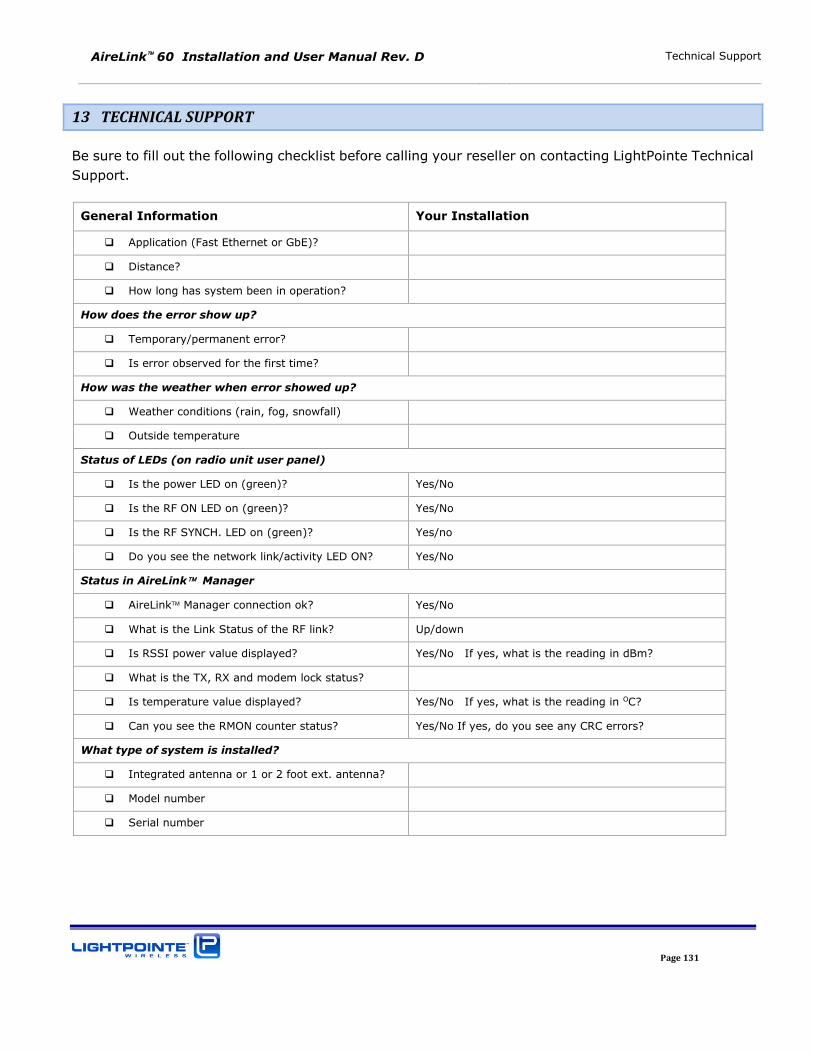
AireLink 60 Installation and User Manual Rev. D Technical Support
Page 131
13 TECHNICAL SUPPORT
Be sure to fill out the following checklist before calling your reseller on contacting LightPointe Technical
Support.
General Information Your Installation
Application (Fast Ethernet or GbE)?
Distance?
How long has system been in operation?
How does the error show up?
Temporary/permanent error?
Is error observed for the first time?
How was the weather when error showed up?
Weather conditions (rain, fog, snowfall)
Outside temperature
Status of LEDs (on radio unit user panel)
Is the power LED on (green)? Yes/No
Is the RF ON LED on (green)? Yes/No
Is the RF SYNCH. LED on (green)? Yes/no
Do you see the network link/activity LED ON? Yes/No
Status in AireLink Manager
AireLink Manager connection ok? Yes/No
What is the Link Status of the RF link? Up/down
Is RSSI power value displayed? Yes/No If yes, what is the reading in dBm?
What is the TX, RX and modem lock status?
Is temperature value displayed? Yes/No If yes, what is the reading in OC?
Can you see the RMON counter status? Yes/No If yes, do you see any CRC errors?
What type of system is installed?
Integrated antenna or 1 or 2 foot ext. antenna?
Model number
Serial number
AireLink 60 Installation and User Manual Rev. D Technical Support
Page 132
13.1 RETURN MATERIAL AUTHORIZATION (RMA) PROCEDURE
Please contact LightPointe before returning any system components for repair or replacement.
RMA products include:
Link head
Standard power supply
13.2 CONTACTING LIGHTPOINTE
Corporate Office
11696 Sorrento Valley Road, Suite #101
San Diego, CA 92121
Phone: +1 (858) 834-4083, Fax: +1 (858) 430-3458
Website: www.lightpointe.com
Email: [email protected]
AireLink 60 Installation and User Manual Rev. D Technical Support
Page 133