lightning and surge protection for led street lighting
TRANSCRIPT

L
LL'
N
PE
LED/enddevice
Lightning and surge protection for LED street lighting Date: 09/2017
✔

These sheets provide you with information on specific technical subjects. They are based on cur-rently known and valid rules and regulations and on our experience. The content of this document is not legally binding and makes no claim to completeness.

Table of contents
Chapter 1 Lightning and surge protection for LED street lighting . . . . . . . . . . . . . .4
Chapter 1.1 Basic principles. . . . . . . . . . . . . . . . . . . . . . . . . . . . . . . . . . . . . . . . . . . . . . . .4
Chapter 1.2 Risks. . . . . . . . . . . . . . . . . . . . . . . . . . . . . . . . . . . . . . . . . . . . . . . . . . . . . . . .4
Chapter 2 Street lighting . . . . . . . . . . . . . . . . . . . . . . . . . . . . . . . . . . . . . . . . . . . . . . . .6
Chapter 2.1 Damage and repair costs . . . . . . . . . . . . . . . . . . . . . . . . . . . . . . . . . . . . . . . .6
Chapter 2.2 Creation of the earthing systems . . . . . . . . . . . . . . . . . . . . . . . . . . . . . . . . . .6
Chapter 2.3 Installation location of the lightning and surge protection . . . . . . . . . . . . . . . .7
Chapter 3 Connection . . . . . . . . . . . . . . . . . . . . . . . . . . . . . . . . . . . . . . . . . . . . . . . . . .9
Chapter 3.1 Parallel connection . . . . . . . . . . . . . . . . . . . . . . . . . . . . . . . . . . . . . . . . . . . . .9
Chapter 3.2 Serial connection . . . . . . . . . . . . . . . . . . . . . . . . . . . . . . . . . . . . . . . . . . . . . .9
Chapter 4 Conclusion . . . . . . . . . . . . . . . . . . . . . . . . . . . . . . . . . . . . . . . . . . . . . . . . . .10
Chapter 5 Overview of surge protection module variants . . . . . . . . . . . . . . . . . . . . .11

4
Lightning and surge protection for LED street lighting
Chapter 1 Lightning and surge protection for LED street lighting
Chapter 1.1 Basic principlesDue to their light intensity, energy efficiency and robustness, LED luminaires are ideally suitable for signal and street lighting. As LED luminaires consume up to 70 per cent less energy than standard lighting, whilst still producing the same luminous power, they can play a significant contribution to the reduction of energy costs.
Chapter 1.2 RisksStreet luminaires are directly exposed to close and distant lightning strikes and surge voltages, on account of their exposed position. These loads can lead to a reduction in the luminous intensity or to the destruction of the electronic ballasts. There is the risk of premature failure and of high repair costs, which extend the amortisation time. Accordingly, a suitable surge protective device (SPD) should be used as protection against damage from lightning or surge voltages.
VDE 0100-100 (IEC 60364) requires protection against lightning and surge volt-ages for people, livestock and property. The protection requirement against the effects of lightning can be determined through a risk analysis according to the lightning protection standard VDE 0185-305 (IEC 62305). Since October 2016, the new VDE 0100-443 (IEC 60364-4-443) has applied, which requires surge protection of any electrical system at least from the supply point. If streets are electrically supplied from buildings, then equipotential bonding with suitable surge protection must be carried out at the entrance to the building.
Lightning strike with destruction through fire and surge voltages
Failure due to surge voltages
Electrical devices of surge voltage category I, e.g. the electronic ballasts or LED drivers, must, according to VDE 0100-443 (IEC 60364-4-443) Table 1, be designed with a surge voltage resistance of 1,500 volts and, in the case of surge voltage category II, of 2,500 volts. However, lightning and switching operations cause surge voltages of up to several 10,000s of volts, which are considerably higher than the named rated surge voltage resistances. Modern LED luminaires require external surge protection against surge voltages.

5
Lightning and surge protection for LED street lighting
Example: Surge voltage on lightning strike
Lightning strike with 100 kA and an earthing resistance of 1 ohm
U = R x l = 1 ohm x 100 kA = 100 kV to the remote earth of the power supply (transformer star point earthing)
The voltage funnel causes the voltage to fall from the impact point.
Distance in m from the impact location
0 30 60 90 120 150 300 450
Voltage in kV to the remote earth
100 36 20 12 9 6 4 3
Table 1: Voltage to the remote earth (transformer star point earthing)

6
Street lighting
Chapter 2 Street lighting
Chapter 2.1 Damage and repair costsIn the field of street lighting, the replacement of the defective components, alongside the hardware costs, also incurs high costs through the use of ele-vating platforms and personnel. Upstream surge protective devices reduce the pulses and protect the luminaire.
Whole streets are supplied via distribution boxes, containing the controllers and protection components. The voltage is fed in via buried cables in the connec-tion compartment of the mast and supplies the luminaire. Surge protective de- vices (SPD) minimise the spread of surge voltages and reduce damage through surge voltages.
Chapter 2.2 Creation of the earthing systemsThe supply cable can be protected against destruction from lightning currents in the earth by an optional earthing line above it. According to the current lightning protection standard VDE 0185-305-3 (DIN EN 62305-3), this earthing line must be located 0.5 metres above the supply cable.
The earthing line compensates potential differences and minimises arcing to the supply cable.
Figure 1: Routing of the earthing lines and the supply cables
Legend:1 Earthing line, uninsulated2 Supply cable
The additional earthing of the lamp mast should be located in areas with an increased number of people, e.g. on car parks or at transport stops (lighting class CE0 to CE5).
Figure 2: Figure 2: Earthing on the lamp mast, e.g. lighting class CE 5
7
Street lighting
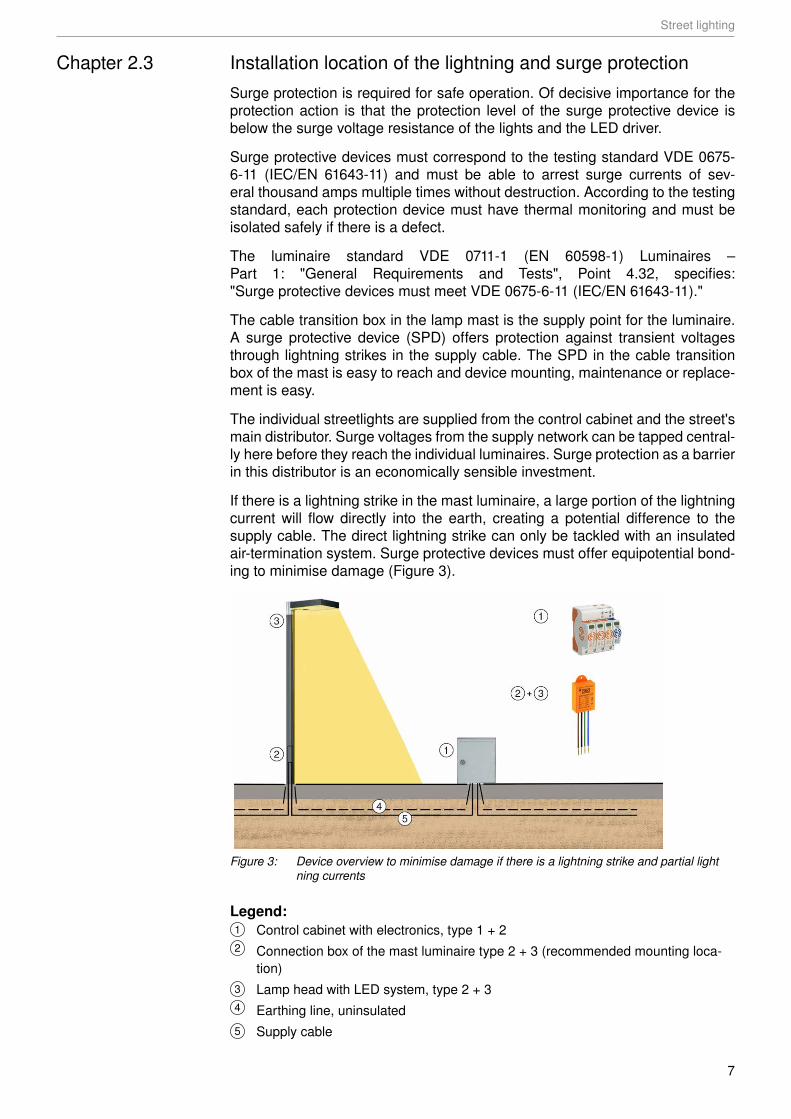
Chapter 2.3 Installation location of the lightning and surge protectionSurge protection is required for safe operation. Of decisive importance for the protection action is that the protection level of the surge protective device is below the surge voltage resistance of the lights and the LED driver.
Surge protective devices must correspond to the testing standard VDE 0675-6-11 (IEC/EN 61643-11) and must be able to arrest surge currents of sev- eral thousand amps multiple times without destruction. According to the testing standard, each protection device must have thermal monitoring and must be isolated safely if there is a defect.
The luminaire standard VDE 0711-1 (EN 60598-1) Luminaires – Part 1: "General Requirements and Tests", Point 4.32, specifies: "Surge protective devices must meet VDE 0675-6-11 (IEC/EN 61643-11)."
The cable transition box in the lamp mast is the supply point for the luminaire. A surge protective device (SPD) offers protection against transient voltages through lightning strikes in the supply cable. The SPD in the cable transition box of the mast is easy to reach and device mounting, maintenance or replace-ment is easy.
The individual streetlights are supplied from the control cabinet and the street's main distributor. Surge voltages from the supply network can be tapped central-ly here before they reach the individual luminaires. Surge protection as a barrier in this distributor is an economically sensible investment.
If there is a lightning strike in the mast luminaire, a large portion of the lightning current will flow directly into the earth, creating a potential difference to the supply cable. The direct lightning strike can only be tackled with an insulated air-termination system. Surge protective devices must offer equipotential bond-ing to minimise damage (Figure 3).
Figure 3: Device overview to minimise damage if there is a lightning strike and partial light ning currents
Legend:1 Control cabinet with electronics, type 1 + 22 Connection box of the mast luminaire type 2 + 3 (recommended mounting loca-
tion)3 Lamp head with LED system, type 2 + 34 Earthing line, uninsulated5 Supply cable

8
Street lighting
Installation location Protection device Description Article no.
1 Control cabinet
Supply V50 3+NPE-280 Type 1 + 2 combination arrestor 5093 5262 Mast
Connection compartment ÜSM-LED-20-230/1P+PE Type 2 + 3 surge protection 5092 4313 Lamp head (optional ‒ check protection class!)
Before the LED driver ÜSM-LED-20-230/1P+PE Type 2 + 3 surge protection 5092 431Table 2: Selection of the protection devices
A lightning strike within 1.5 km generates a surge voltage which hits the lighting via the supply cable (Figure 4). These surge voltages can destroy electronic components. Here, surge protective devices must offer equipotential bonding to minimise damage (Figure 4).
Figure 4: Device overview to minimise damage in case of surge voltages
Legend:1 Control cabinet with electronics, type 22 Connection box of the mast luminaire type 2 + 3 (recommended mounting loca-
tion)3 Lamp head with LED system, type 2 + 34 Earthing line, uninsulated5 Supply cable
Installation location Protection device Description Article no.
1 Control cabinet
Supply, 3-phase V20 3+NPE-280 Type 2 surge protection 5095 2532 Mast
Connection compartment ÜSM-LED-20-230/1P+PE Type 2 + 3 surge protection 5092 4313 Lamp head (optional ‒ check protection class!)
Before the LED driver ÜSM-LED-20-230/1P+PE Type 2 + 3 surge protection 5092 431Table 3: Selection of the protective devices
Inductions through new lightning strikes are considerably reduced through a metallic mast and a metallic housing. In this case, the surge protection in the mast connection compartment is easily accessible and easy to check.

9
Connection
Chapter 3 ConnectionThe surge protective device ÜSM-LED-20-230/1P+PE can be installed in series with or in parallel to the luminaires. The differing connection can be used to maximise availability (parallel connection) or to switch off the luminaire if there is a defect on the protection device (serial connection).
Chapter 3.1 Parallel connectionThe surge protective device is located upstream of the LED luminaire.
L
N
PE
L
L'LED/enddevice
Figure 5: Example ÜSM-20-230/1P+PE: 5092431
Failure behaviour: The display on the ÜSM-LED-20-230/1P+PE surge protective device goes out. The surge protection is disconnected. The LED luminaire remains lit without protection.
Chapter 3.2 Serial connectionThe surge protection is switched in series to the LED luminaire.
L
LL'
N
PE
LED/enddevice
Figure 6: Example ÜSM-20-230/1P+PE: 5092431
Failure behaviour: The display on the ÜSM-LED-20-230/1P+PE surge protec-tive device goes out. The surge protection and the circuit (L') are disconnected. The failure is additionally signalled by the luminaire going out.

10
Conclusion
Chapter 4 ConclusionSurge protective devices upstream of the electronic LED drivers are a safe bar-rier against surge voltages. The lifespan of the LED luminaires is guaranteed, securing the investment.
In the field of street lighting, enormous cost savings for energy are possible. However, premature failure from surge voltage damage can push the return on investment back into the future. Suitable protection measures allow the avoid-ance of unnecessary maintenance work and a long lifespan, availability and investment.
The surge protective devices (SPDs) in the central street distributor or control cabinet and in the cable transition box of the mast offer an effective, stepped protection concept against surge voltages.
For lighting systems, the OBO ProtectPlus range offers secure solutions, for example.

11
Overview of surge protection module variants
Chapter 5 Overview of surge protection module variants
Type ÜSM-20-230/1P+PE
ÜSM-20-230/1PE65
ÜSM-10-230/1P-0
ÜSM-10-230/1P+PE
ÜSM-10-230/2P-0
ÜSM-10-230/2P+PE
Version 1-pole + NPE for SK I
1-pole + NPE for SK I
1-pole without NPE for SK II
1-pole + NPE for SK I
2-pole without NPE for SK II
2-pole + NPE for SK I
SPD to EN 61643-11 Type 2 + 3 Type 2 + 3 Type 2 + 3 Type 2 + 3 Type 2 + 3 Type 2 + 3Maximum continuous voltage 255 V (AC) 255 V (AC) 255 V (AC) 255 V (AC) 255 V (AC) 255 V (AC)Max. discharge current (8/20) 20 kA 20 kA 10 kA 10 kA 10 kA 10 kANominal discharge current (8/20)
10 kA 10 kA 5 kA 5 kA 5 kA 5 kA
Idle voltage 10 kV 10 kV 10 kV 10 kV 10 kV 10 kVProtection level (L-N / L/N-PE) 1,300 / 1,300
V1,500 / 1,600 V
1,300 V 1,300 / 1,300 V
1,300 V 1,300 / 1,300 V
Protection rating IP20 IP65 IP20 IP20 IP20 IP20Item no. 5092 43 1 5092 43 3 5092 42 0 5092 42 2 5092 42 4 5092 42 6
OBO Bettermann GmbH & Co. KG
Langer Brauck 25
58640 Iserlohn, Germany
GERMANY
Customer Service Germany
Tel.: +49 (0)2371 7899-2000
Fax: +49 (0)2371 7899-2500
www.obo-bettermann.com
OB
O B
ette
rman
n O
PTO
170
471
Dat
e 09
/201
7 E
N I
tem
num
ber 9
1319
42
Building Connections