lighting tracks and adapters 2 for innovative luminaries
TRANSCRIPT
Lighting tracks and adaptersfor innovative luminaries
2
3
EUTR
AC
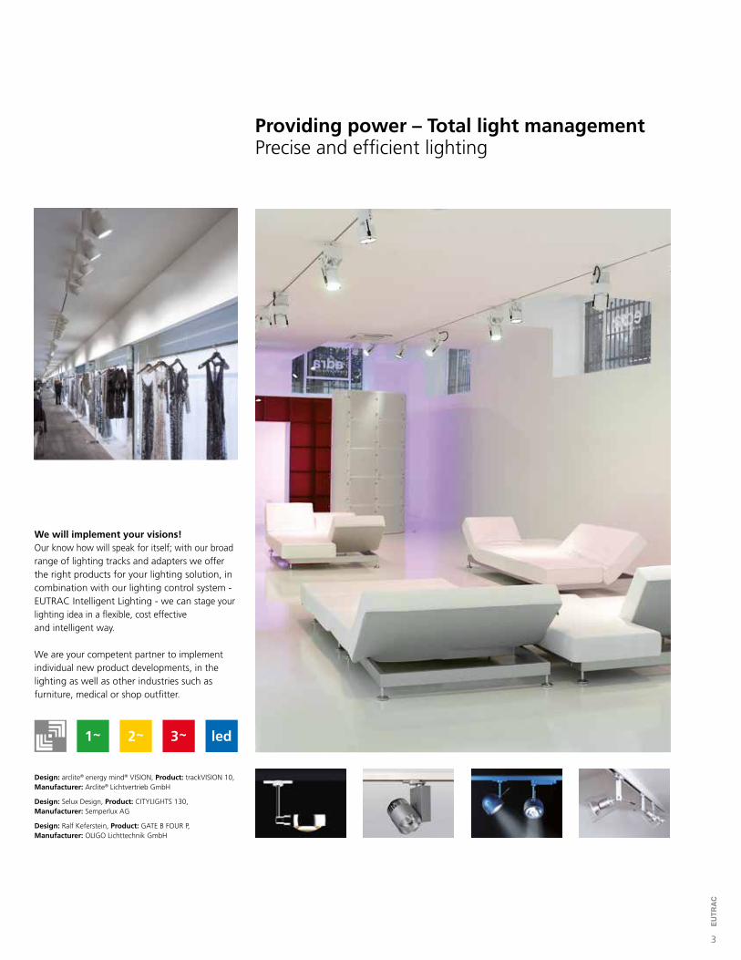
Providing power – Total light managementPrecise and efficient lighting
Design: arclite® energy mind® VISION, Product: trackVISION 10,Manufacturer: Arclite® Lichtvertrieb GmbH
Design: Selux Design, Product: CITYLIGHTS 130,Manufacturer: Semperlux AG
Design: Ralf Keferstein, Product: GATE B FOUR P,Manufacturer: OLIGO Lichttechnik GmbH
We will implement your visions!Our know how will speak for itself; with our broad range of lighting tracks and adapters we offer the right products for your lighting solution, in combination with our lighting control system - EUTRAC Intelligent Lighting - we can stage your lighting idea in a flexible, cost effective and intelligent way.
We are your competent partner to implement individual new product developments, in the lighting as well as other industries such as furniture, medical or shop outfitter.
4
EUTR
AC
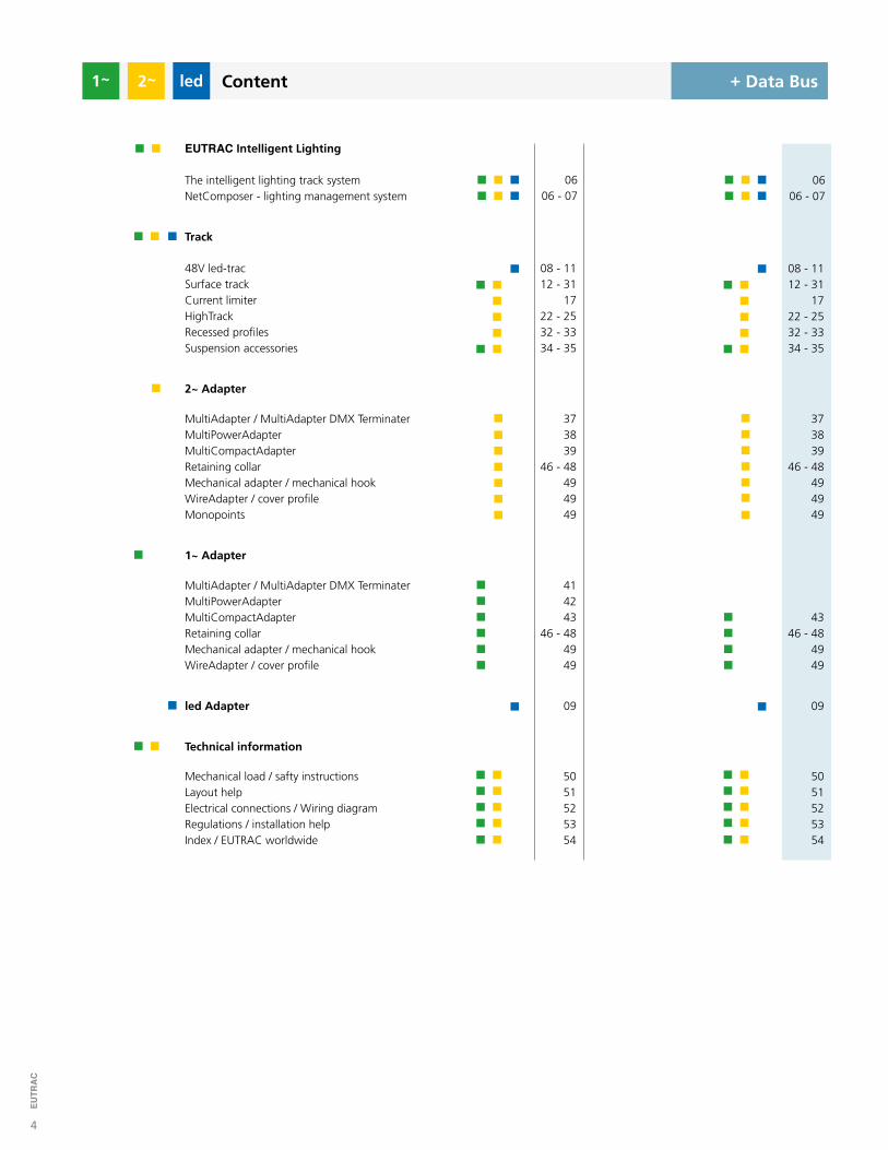
48V led-tracSurface trackCurrent limiterHighTrackRecessed profilesSuspension accessories
0606 - 07
The intelligent lighting track system NetComposer - lighting management system
EUTRAC Intelligent Lighting
0606 - 07
5051525354
5051525354
414243
46 - 484949
MultiAdapter / MultiAdapter DMX TerminaterMultiPowerAdapterMultiCompactAdapterRetaining collarMechanical adapter / mechanical hookWireAdapter / cover profile
1~ Adapter
4346 - 48
4949
373839
46 - 48494949
MultiAdapter / MultiAdapter DMX TerminaterMultiPowerAdapterMultiCompactAdapterRetaining collarMechanical adapter / mechanical hookWireAdapter / cover profileMonopoints
2~ Adapter
373839
46 - 48494949
Mechanical load / safty instructionsLayout helpElectrical connections / Wiring diagramRegulations / installation helpIndex / EUTRAC worldwide
Technical information
+ Datenbus+ Data Bus
08 - 1112 - 31
1722 - 2532 - 3334 - 35
Track
08 - 1112 - 31
1722 - 2532 - 3334 - 35
Content2
led Adapter 09 09
5
EUTR
AC
silver
blackwhite
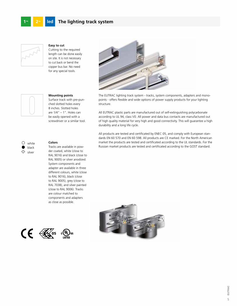
The lighting track system
ColorsTracks are available in pow-der coated, white (close to RAL 9016) and black (close to RAL 9005) or silver anodized. System components and adapter are available in three different colours, white (close to RAL 9016), black (close to RAL 9005), grey (close to RAL 7038), and silver painted (close to RAL 9006). Tracks are colour matched to components and adapters as close as possible.
Easy to cutCutting to the requiredlength can be done easily on site. It is not necessaryto cut back or bend thecopper bus bar. No need for any special tools.
Mounting pointsSurface track with pre-pun-ched slotted holes every 8 inches. Slotted holes are 1/4“ – 1“. Holes can be easily opened with a screwdriver or a similar tool.
The EUTRAC lighting track system - tracks, system components, adapters and mono-points - offers flexible and wide options of power supply products for your lighting structure.
All EUTRAC plastic parts are manufactured out of self-extinguishing polycarbonate according to UL 94, class V0. All power and data bus contacts are manufactured out of high quality material for very high and good connectivity. This will guarantee a high durability and a long life cycle.
All products are tested and certificated by ENEC 05, and comply with European stan-dards EN 60 570 and EN 60 598. All products are CE marked. For the North American market the products are tested and certificated according to the UL standards. For the Russian market products are tested and certificated according to the GOST standard.
2
6
EUTR
AC
For further information visit www.intelligentlighting.de
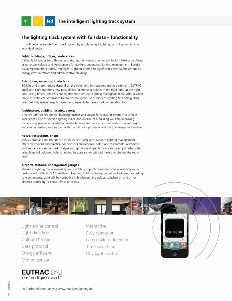
The lighting track system with full data – functionality…. will become an intelligent track system by simply using a lighting control system in yourindividual project:
Data protocol
Energy efficient
Motion sensor
Light scene controlLight direction
Colour change
Day light control
Interactive
Easy operation
Lamp failure detection
Time switching
Public buildings, offices, conferencesCalling light scenes for different activities, motion sensors connected to light fixtures in offices or other workplaces and light sensors for daylight-dependent lighting management. Besides visual ergonomics, EUTRAC Intelligent Lighting offers also significant potential for savings on energy costs in offices and administrative buildings.
Exhibitions, museums, trade fairsExhibits and presentations depend on the right light. In museums and at trade fairs, EUTRACIntelligent Lighting offers new possibilities for showing objects in the right light, at the right time. Using timers, dimmers and light/motion sensors, lighting management can offer a whole range of technical possibilities to ensure intelligent use of modern lighting technology. This does not only save energy but may bring benefits for reasons of conservation too.
Architecture, building facades, eventsCreative light scenes convert building facades and stages for shows or events into unique experiences. Use of specific lighting inside and outside of a building will help improving corporate appearance. In addition media facades are used to communicate visual messages and can be flexibly programmed with the help of a professional lighting management system.
Hotels, restaurants, shopsToday’s products and brands are set in scenes using light. Modern lighting management offers convenient and practical solutions for showrooms, hotels and restaurants. Automatic light sequences can be used for dynamic lighting in shops. A room can be simply redecorated using blend of coloured light, changing its appearance without having to change the roomitself.
Airports, stations, underground garagesThanks to lighting management systems, lighting in public areas become increasingly more professional. With EUTRAC Intelligent Lighting, light can be optimised and adjusted according to requirements. Light will be controlled in brightness and colour, switched on and off or dimmed according to needs, times or events.
The intelligent lighting track system2
12
EUTR
AC
+ Data bus
1 7/16“
1 1/4“
1 7/16“
1 1/4“
black silverwhite
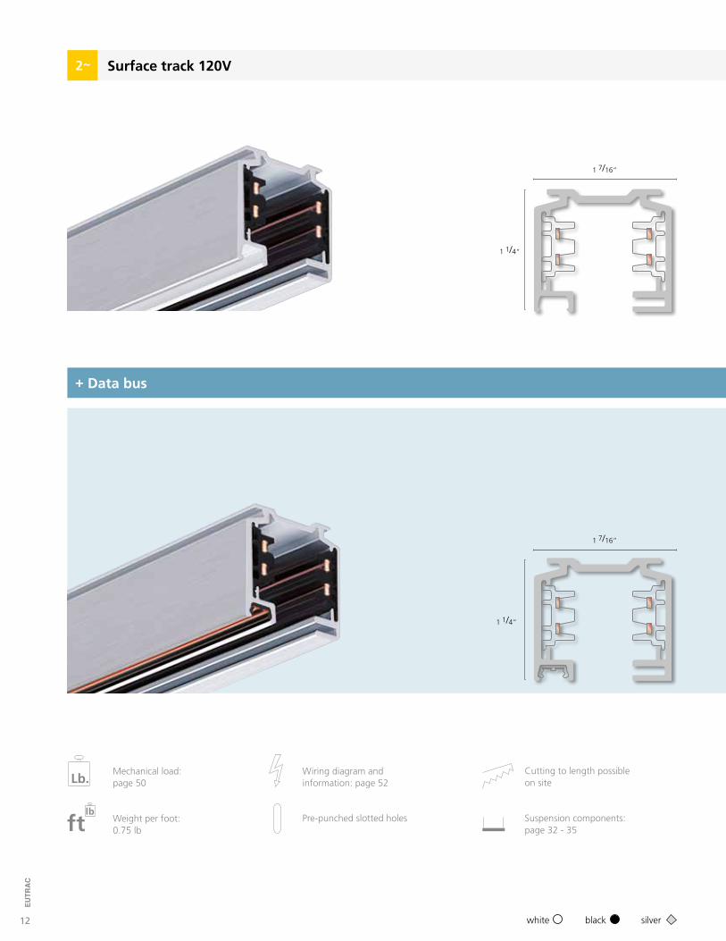
Surface track 120V2
Cutting to length possibleon site
Wiring diagram andinformation: page 52Lb.
Mechanical load: page 50
ftlb
Weight per foot:0.75 lb
Pre-punched slotted holes Suspension components:page 32 - 35
13
EUTR
AC
For further information visit www.eutrac.com
3
3
3
4 ft.
8 ft.
12 ft.
233-10
233-20
233-30
1
1
1
2
2
2
+ Data bus
Surface track 120V2
3
3
3
4 ft.
8 ft.
12 ft.
230-10
230-20
230-30
1
1
1
2
2
2
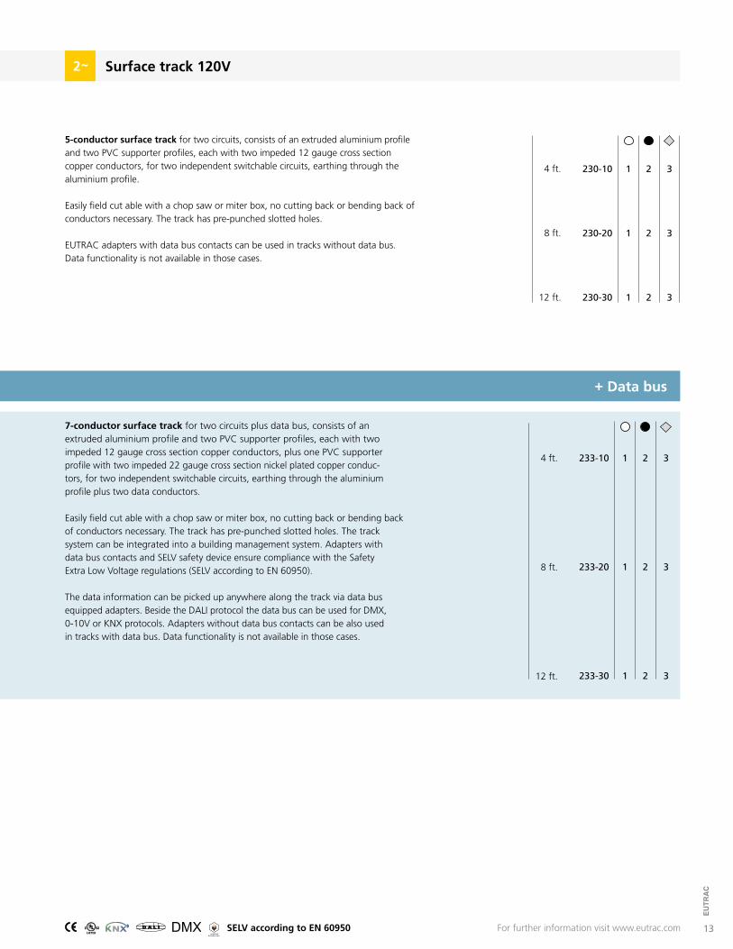
5-conductor surface track for two circuits, consists of an extruded aluminium profile and two PVC supporter profiles, each with two impeded 12 gauge cross section copper conductors, for two independent switchable circuits, earthing through the aluminium profile.
Easily field cut able with a chop saw or miter box, no cutting back or bending back of conductors necessary. The track has pre-punched slotted holes.
EUTRAC adapters with data bus contacts can be used in tracks without data bus.Data functionality is not available in those cases.
7-conductor surface track for two circuits plus data bus, consists of an extruded aluminium profile and two PVC supporter profiles, each with two impeded 12 gauge cross section copper conductors, plus one PVC supporter profile with two impeded 22 gauge cross section nickel plated copper conduc-tors, for two independent switchable circuits, earthing through the aluminium profile plus two data conductors.
Easily field cut able with a chop saw or miter box, no cutting back or bending back of conductors necessary. The track has pre-punched slotted holes. The track system can be integrated into a building management system. Adapters with data bus contacts and SELV safety device ensure compliance with the Safety Extra Low Voltage regulations (SELV according to EN 60950).
The data information can be picked up anywhere along the track via data bus equipped adapters. Beside the DALI protocol the data bus can be used for DMX, 0-10V or KNX protocols. Adapters without data bus contacts can be also used in tracks with data bus. Data functionality is not available in those cases.
R SELV according to EN 60950
14
EUTR
AC
black silverwhite
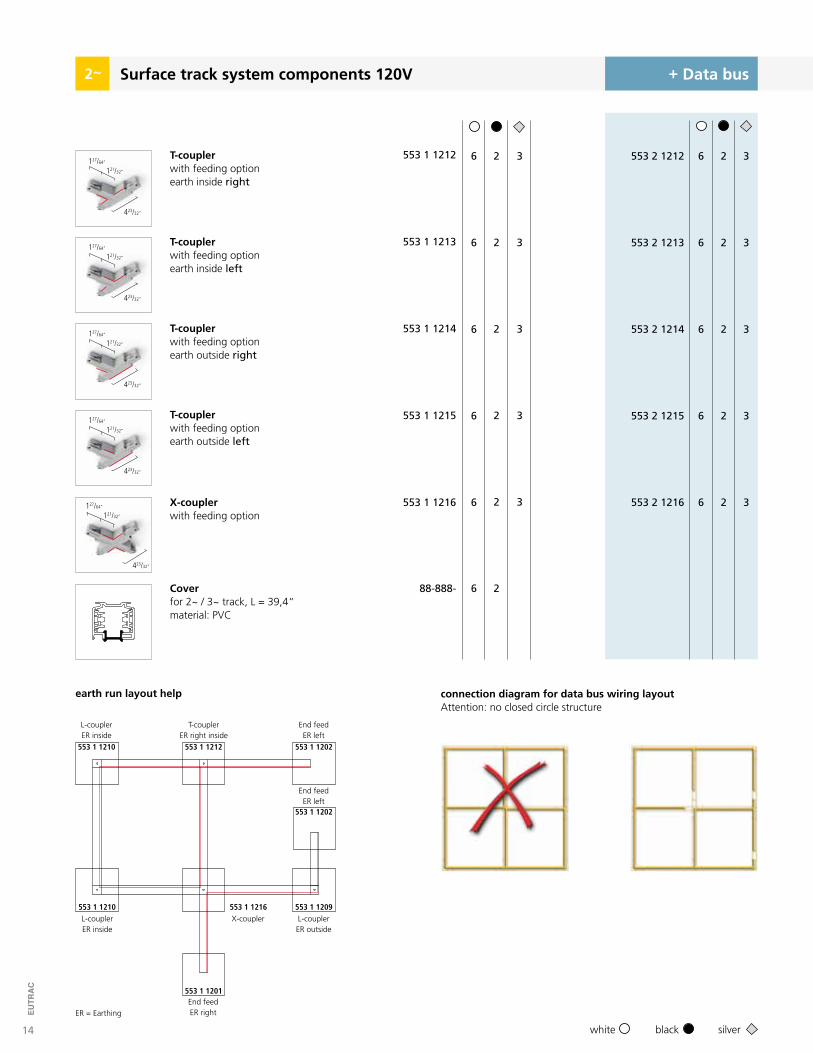
Coverfor 2~ / 3~ track, L = 39,4“material: PVC
Surface track system components 120V + Data bus
553 1 1212
553 1 1213
553 1 1214
553 1 1215
553 1 1216
6
6
6
6
6
2
2
2
2
2
553 2 1212
553 2 1213
553 2 1214
553 2 1215
553 2 1216
3
3
3
3
3
6
6
6
6
6
2
2
2
2
2
3
3
3
3
3
2
ER = Earthing
553 1 1210 553 1 1212
553 1 1201
553 1 1202
553 1 1202
553 1 1209553 1 1210 553 1 1216
earth run layout help
L-couplerER inside
T-couplerER right inside
End feedER right
End feedER left
End feedER left
L-couplerER outside
X-couplerL-couplerER inside
connection diagram for data bus wiring layout Attention: no closed circle structure
X-couplerwith feeding option
T-couplerwith feeding optionearth inside right
T-couplerwith feeding optionearth inside left
T-couplerwith feeding optionearth outside left
T-couplerwith feeding optionearth outside right
127/64“
121/32“
423/32“
127/64“
121/32“
423/32“
127/64“
121/32“
423/32“
127/64“
121/32“
423/32“
127/64“
121/32“
423/32“
88-888- 6 2
15
EUTR
AC
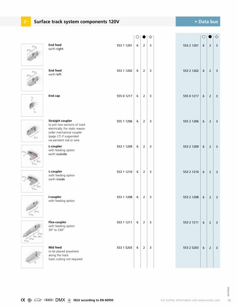
Surface track system components 120V + Data bus
6
6
6
6
6
6
6
6
6
2
2
2
2
2
2
2
2
2
3
3
3
3
3
3
3
3
3
553 1 1201
553 1 1202
555 0 1217
555 1 1206
553 1 1209
553 1 1210
553 1 1208
553 1 1211
553 1 5203
6
6
6
6
6
6
6
6
6
2
2
2
2
2
2
2
2
2
3
3
3
3
3
3
3
3
3
553 2 1201
553 2 1202
555 0 1217
555 2 1206
553 2 1209
553 2 1210
553 2 1208
553 2 1211
553 2 5203
2
End feedearth right
L-couplerwith feeding optionearth outside
I-couplerwith feeding option
Flex-couplerwith feeding option30° to 330°
Mid feedto be placed anywhere along the track track cutting not required
Straight couplerto join two sections of trackelectrically. For static reason order mechanical coupler (page 27) if suspended via pendant rod or wire
End feedearth left
L-couplerwith feeding optionearth inside
End cap
For further information visit www.eutrac.com
27/16“
1/4“
1/8“
5/16“
253/64“
127/64“
253/64“
127/64“
127/64“
35/64“
121/32“
127/64“
127/64“
127/64“
253/64“
253/64“
35/64“
121/32“
423/32“
5“
33/16“- 43/4“
R SELV according to EN 60950
16
EUTR
AC
2
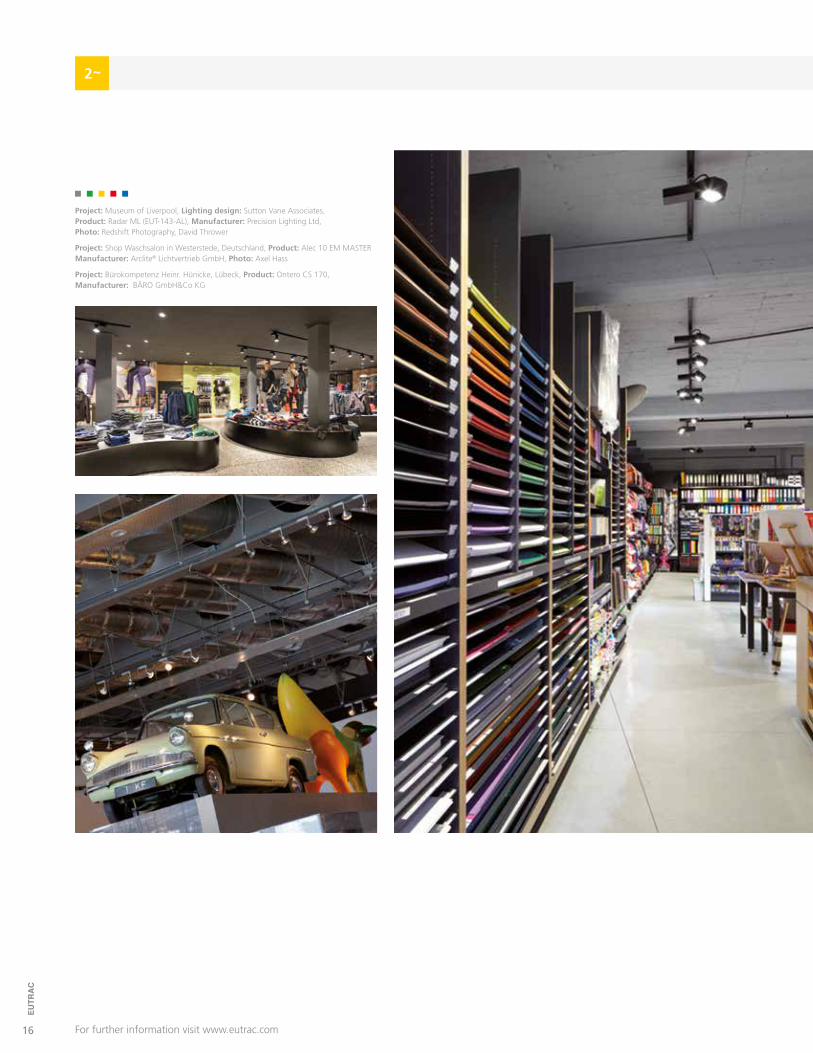
Project: Museum of Liverpool, Lighting design: Sutton Vane Associates,Product: Radar ML (EUT-143-AL), Manufacturer: Precision Lighting Ltd,Photo: Redshift Photography, David Thrower
Project: Shop Waschsalon in Westerstede, Deutschland, Product: Alec 10 EM MASTER Manufacturer: Arclite® Lichtvertrieb GmbH, Photo: Axel Hass
Project: Bürokompetenz Heinr. Hünicke, Lübeck, Product: Ontero CS 170,Manufacturer: BÄRO GmbH&Co KG
For further information visit www.eutrac.com
17
EUTR
AC
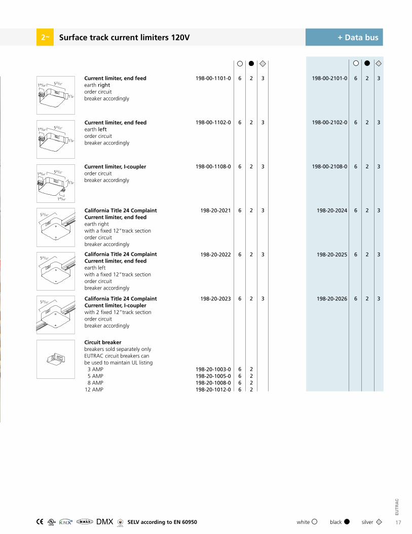
Surface track current limiters 120V2 + Data bus
Current limiter, end feedearth rightorder circuit breaker accordingly
3
3
3
6
6
6
2
2
2
198-00-1101-0
198-00-1102-0
198-00-1108-0
198-00-2101-0
198-00-2102-0
198-00-2108-0
3
3
3
6
6
6
2
2
2
Circuit breakerbreakers sold separately only EUTRAC circuit breakers can be used to maintain UL listing 3 AMP 5 AMP 8 AMP 12 AMP
6666
2222
198-20-1003-0198-20-1005-0198-20-1008-0198-20-1012-0
black silverwhite
149/64“523/32“
17/8“
Current limiter, end feedearth leftorder circuitbreaker accordingly
149/64“523/32“
17/8“
3
3
3
6
6
6
2
2
2
198-20-2021
198-20-2022
198-20-2023
198-20-2024
198-20-2025
198-20-2026
3
3
3
6
6
6
2
2
2
California Title 24 Complaint Current limiter, end feedearth rightwith a fixed 12”track sectionorder circuit breaker accordingly
California Title 24 Complaint Current limiter, end feedearth leftwith a fixed 12”track sectionorder circuit breaker accordingly
California Title 24 Complaint Current limiter, I-couplerwith 2 fixed 12”track sectionorder circuit breaker accordingly
149/64“
Current limiter, I-couplerorder circuitbreaker accordingly
149/64“523/32“
523/32“
523/32“
523/32“
17/8“
R SELV according to EN 60950

18
EUTR
AC
Surface track 277V
1 7/16“
1 6/11“
2
black silverwhite
+ Data bus
1 7/16“
1 1/4“
Cutting to length possibleon site
Wiring diagram andinformation: page 52Lb.
Mechanical load: page 50
ftlb
Weight per foot:0.75 lb
Pre-punched slotted holes Suspension components:page 32 - 35
19
EUTR
AC
Surface track 277V2
3
3
3
4 ft.
8 ft.
12 ft.
244-12
244-24
244-36
1
1
1
2
2
2
+ Data bus
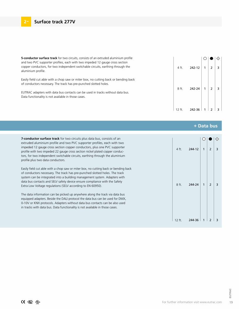
7-conductor surface track for two circuits plus data bus, consists of an extruded aluminium profile and two PVC supporter profiles, each with two impeded 12 gauge cross section copper conductors, plus one PVC supporter profile with two impeded 22 gauge cross section nickel plated copper conduc-tors, for two independent switchable circuits, earthing through the aluminium profile plus two data conductors.
Easily field cut able with a chop saw or miter box, no cutting back or bending back of conductors necessary. The track has pre-punched slotted holes. The track system can be integrated into a building management system. Adapters with data bus contacts and SELV safety device ensure compliance with the Safety Extra Low Voltage regulations (SELV according to EN 60950).
The data information can be picked up anywhere along the track via data bus equipped adapters. Beside the DALI protocol the data bus can be used for DMX, 0-10V or KNX protocols. Adapters without data bus contacts can be also used in tracks with data bus. Data functionality is not available in those cases.
3
3
3
4 ft.
8 ft.
12 ft.
242-12
242-24
242-36
1
1
1
2
2
2
5-conductor surface track for two circuits, consists of an extruded aluminium profile and two PVC supporter profiles, each with two impeded 12 gauge cross section copper conductors, for two independent switchable circuits, earthing through the aluminium profile.
Easily field cut able with a chop saw or miter box, no cutting back or bending back of conductors necessary. The track has pre-punched slotted holes.
EUTRAC adapters with data bus contacts can be used in tracks without data bus.Data functionality is not available in those cases.
For further information visit www.eutrac.com

20
EUTR
AC
black silverwhite
Coverfor 2~ / 3~ track, L = 39,4“material: PVC
Surface track system components 277V2
ER = Earthing
554 1 1210 554 1 1212
554 1 1201
554 1 1202
554 1 1202
554 1 1209554 1 1210 554 1 1216
L-couplerER inside
T-couplerER right inside
End feedER right
End feedER left
End feedER left
L-couplerER outside
X-couplerL-couplerER inside
X-couplerwith feeding option
T-couplerwith feeding optionearth inside right
T-couplerwith feeding optionearth inside left
T-couplerwith feeding optionearth outside left
T-couplerwith feeding optionearth outside right
earth run layout help
127/64“
121/32“
423/32“
127/64“
121/32“
423/32“
127/64“
121/32“
423/32“
127/64“
121/32“
423/32“
127/64“
121/32“
423/32“
554 1 1212
554 1 1213
554 1 1214
554 1 1215
554 1 1216
6
6
6
6
6
2
2
2
2
2
554 2 1212
554 2 1213
554 2 1214
554 2 1215
554 2 1216
3
3
3
3
3
6
6
6
6
6
2
2
2
2
2
3
3
3
3
3
88-888- 6 2
+ Data bus

21
EUTR
AC
Surface track system components 277V2
End feedearth right
L-couplerwith feeding optionearth outside
I-couplerwith feeding option
Flex-couplerwith feeding option30° to 330°
Straight couplerto join two sections of trackelectrically. For static reason order mechanical coupler (page 27) if suspended via pendant rod or wire
End feedearth left
L-couplerwith feeding optionearth inside
End cap
For further information visit www.eutrac.com
27/16“
1/4“
1/8“
253/64“
127/64“
253/64“
127/64“
127/64“
35/64“
121/32“
127/64“
127/64“
127/64“
253/64“
253/64“
35/64“
121/32“
423/32“
33/16“- 43/4“
R SELV according to EN 60950
6
6
6
6
6
6
6
6
2
2
2
2
2
2
2
2
3
3
3
3
3
3
3
3
554 1 1201
554 1 1202
554 0 1217
554 1 1206
554 1 1209
554 1 1210
554 1 1208
554 1 1211
6
6
6
6
6
6
6
6
2
2
2
2
2
2
2
2
3
3
3
3
3
3
3
3
554 2 1201
554 2 1202
554 0 1217
554 2 1206
554 2 1209
554 2 1210
554 2 1208
554 2 1211
+ Data bus
22
EUTR
AC
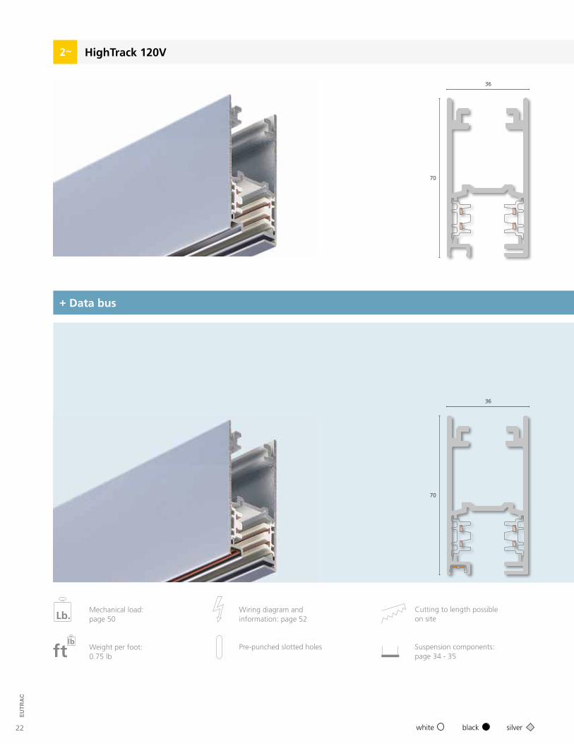
HighTrack 120V2
+ Data bus
36
70
36
70
black silverwhite
Cutting to length possibleon site
Wiring diagram andinformation: page 52Lb.
Mechanical load: page 50
ftlb
Weight per foot:0.75 lb
Pre-punched slotted holes Suspension components:page 34 - 35
23
EUTR
AC
HighTrack2
2 m
3 m
4 m
193-20
193-30
193-40
3
3
3
6
6
6
2
2
2
3
3
3
2 m
3 m
4 m
293-20
293-30
293-40
6
6
6
2
2
2
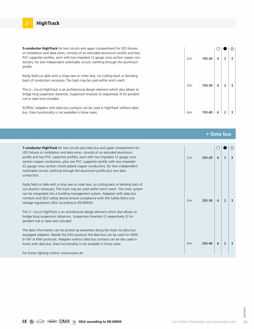
5-conductor HighTrack for two circuits and upper compartment for LED fixtures or installation and data wires, consists of an extruded aluminium profile and two PVC supporter profiles, each with two impeded 12 gauge cross section copper con-ductors, for two independent switchable circuits, earthing through the aluminium profile.
Easily field cut able with a chop saw or miter box, no cutting back or bending back of conductors necessary. The track may be used within arm’s reach.
The 2~ circuit HighTrack is an architectural design element which also allows to bridge long suspension distances. Suspension brackets (2 respectively 3) for pendant rod or steel wire included.
EUTRAC adapters with data bus contacts can be used in HighTrack without data bus. Data functionality is not available in those cases.
7-conductor HighTrack for two circuits plus data bus and upper compartment for LED fixtures or installation and data wires, consists of an extruded aluminium profile and two PVC supporter profiles, each with two impeded 12 gauge cross section copper conductors, plus one PVC supporter profile with two impeded 22 gauge cross section nickel plated copper conductors, for two independent switchable circuits, earthing through the aluminium profile plus two data conductors.
Easily field cut able with a chop saw or miter box, no cutting back or bending back of con-ductors necessary. The track may be used within arm’s reach. The track system can be integrated into a building management system. Adapters with data bus contacts and SELV safety device ensure compliance with the Safety Extra Low Voltage regulations (SELV according to EN 60950).
The 2~ circuit HighTrack is an architectural design element which also allows to bridge long suspension distances. Suspension brackets (2 respectively 3) for pendant rod or steel wire included.
The data information can be picked up anywhere along the track via data bus equipped adapters. Beside the DALI protocol the data bus can be used for DMX, 0-10V or KNX protocols. Adapters without data bus contacts can be also used in tracks with data bus. Data functionality is not available in those cases.
For Eutrac lighting control: www.eutrac.de
For further information visit www.eutrac.comR SELV according to EN 60950
+ Data bus
24
EUTR
AC
HighTrack system components2
black silverwhite
+ Data bus
6
6
6
6
6
2
2
2
2
2
553 2 2212
553 2 2213
553 2 2214
553 2 2215
553 2 2216
3
3
3
3
3
6
6
6
6
6
2
2
2
2
2
553 1 2212
553 1 2213
553 1 2214
553 1 2215
553 1 2216
3
3
3
3
3
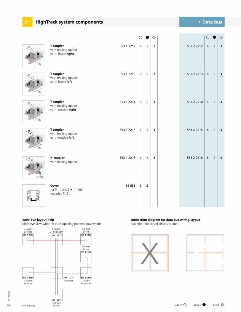
Coverfor 3~ track, L = 1 metermaterial: PVC
88 888 6 2
T-couplerwith feeding optionearth inside right
T-couplerwith feeding optionearth outside right
X-couplerwith feeding option
T-couplerwith feeding optionearth inside left
T-couplerwith feeding optionearth outside left
ER = Earthing
555 1 2210 555 1 2212
555 1 2201
555 1 2202
555 1 2202
555 1 2209555 1 2210 555 1 2216
L-couplerER inside
T-couplerER inside right
End feedER right
End feedER left
End feedER left
L-couplerER outside
X-couplerL-couplerER inside
connection diagram for data bus wiring layout Attention: no closed circle structure
earth run layout helpbird’s eye view with the track opening pointed downwards
4236
120
4236
120
4236
120
4236
120
4236
120
4236
120
25
EUTR
AC
HighTrack system components2
For further information visit www.eutrac.comR SELV according to EN 60950
+ Data bus
6
6
6
6
6
6
6
6
6
2
2
2
2
2
2
2
2
2
3
3
3
3
3
3
3
3
553 1 2201
553 1 2202
553 0 2217
553 1 2206
553 1 2209
553 1 2210
553 1 2208
553 1 2211
553 1 5203
6
6
6
6
6
6
6
6
6
2
2
2
2
2
2
2
2
2
3
3
3
3
3
3
3
3
553 2 2201
553 2 2202
553 0 2217
553 2 2206
553 2 2209
553 2 2210
553 2 2208
553 2 2211
553 2 5203
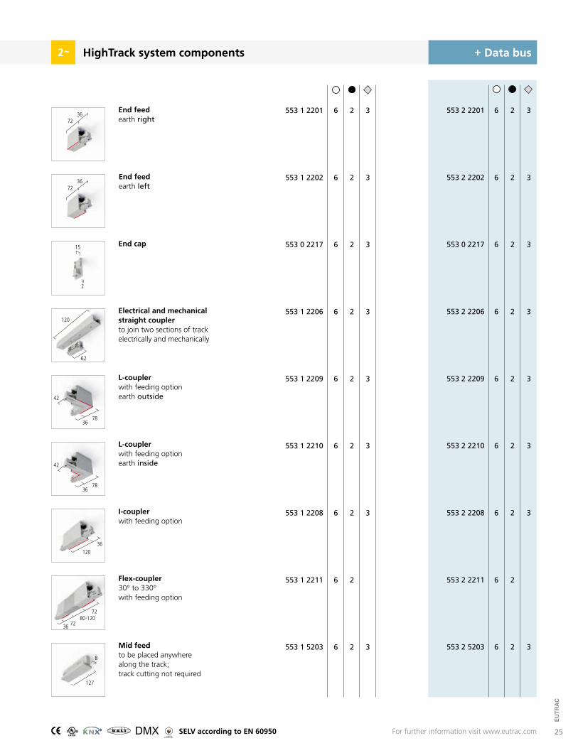
End feedearth right
L-couplerwith feeding optionearth outside
I-couplerwith feeding option
Flex-coupler30° to 330°with feeding option
Mid feedto be placed anywhere along the track; track cutting not required
Electrical and mechanical straight coupler to join two sections of trackelectrically and mechanically
End feedearth left
L-couplerwith feeding optionearth inside
End cap15
2
72
72
36
36
62
120
36
36
42
42
78
78
36120
80-120
36 72
72
127
8
28
EUTR
AC
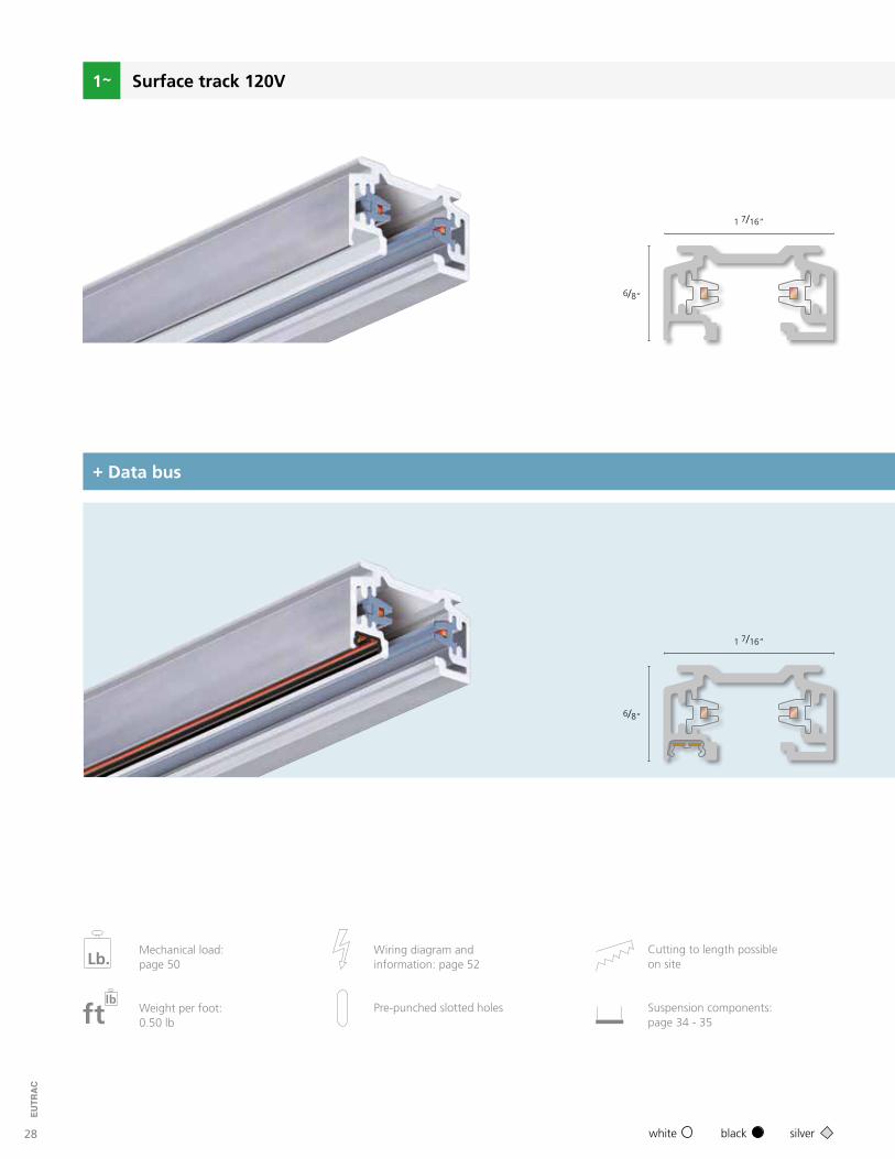
1 7/16“
6/8“
6/8“
1 7/16“
Surface track 120V
black silverwhite
+ Data bus
Cutting to length possibleon site
Wiring diagram andinformation: page 52Lb.
Mechanical load: page 50
ftlb
Weight per foot:0.50 lb
Pre-punched slotted holes Suspension components:page 34 - 35
29
EUTR
AC
3
3
3
4 ft.
8 ft.
12 ft.
235-12
235-24
235-36
1
1
1
2
2
2
4 ft.
8 ft.
12 ft.
238-12
238-24
238-36
1
1
1
2
2
2
3
3
3
Surface track 120V
+ Data bus
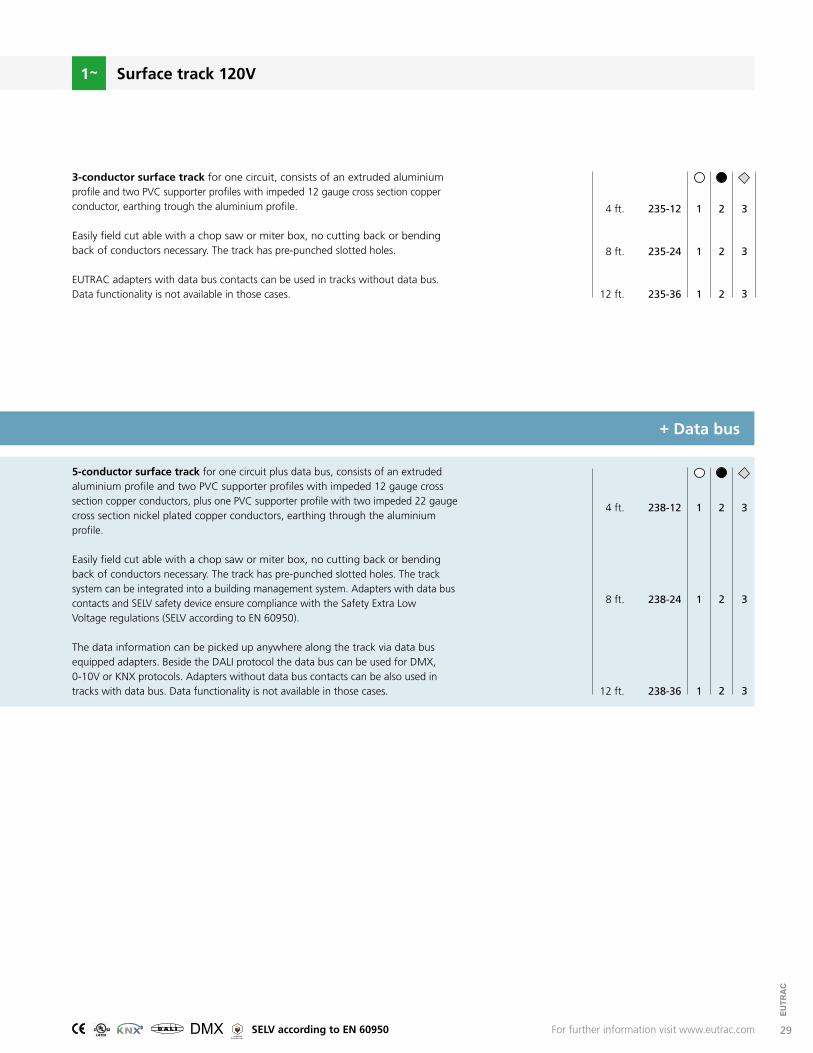
3-conductor surface track for one circuit, consists of an extruded aluminium profile and two PVC supporter profiles with impeded 12 gauge cross section copper conductor, earthing trough the aluminium profile.
Easily field cut able with a chop saw or miter box, no cutting back or bending back of conductors necessary. The track has pre-punched slotted holes.
EUTRAC adapters with data bus contacts can be used in tracks without data bus. Data functionality is not available in those cases.
5-conductor surface track for one circuit plus data bus, consists of an extruded aluminium profile and two PVC supporter profiles with impeded 12 gauge cross section copper conductors, plus one PVC supporter profile with two impeded 22 gauge cross section nickel plated copper conductors, earthing through the aluminium profile.
Easily field cut able with a chop saw or miter box, no cutting back or bending back of conductors necessary. The track has pre-punched slotted holes. The track system can be integrated into a building management system. Adapters with data bus contacts and SELV safety device ensure compliance with the Safety Extra Low Voltage regulations (SELV according to EN 60950).
The data information can be picked up anywhere along the track via data bus equipped adapters. Beside the DALI protocol the data bus can be used for DMX, 0-10V or KNX protocols. Adapters without data bus contacts can be also used in tracks with data bus. Data functionality is not available in those cases.
For further information visit www.eutrac.comR SELV according to EN 60950
30
EUTR
AC
+ Data busSurface track system components 120V
3
3
3
1
1
1
2
2
2
98-531-
98-532-
98-534-
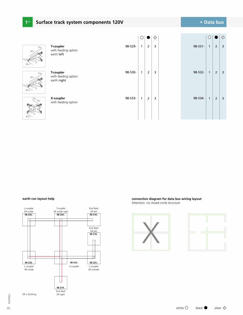
T-couplerwith feeding optionearth left
X-couplerwith feeding option
T-couplerwith feeding optionearth right
3
3
3
1
1
1
2
2
2
98-529-
98-530-
98-533-
black silverwhite
ER = Earthing
15/8“
41/4“
5“
33/16“
15/16“
15/8“16/8“
5“
33/16“
15/8“
41/4“
5“
33/16“
15/16“
98-526-. 98-530-.
98-519-.
98-518-.
98-518-.
98-525-.98-526-. 98-533-.
L-couplerER inside
T-couplerER inside right
End feedER right
End feedER left
End feedER left
L-couplerER outside
X-couplerL-couplerER inside
earth run layout help connection diagram for data bus wiring layout Attention: no closed circle structure
31
EUTR
AC
+ Data busSurface track system components 120V
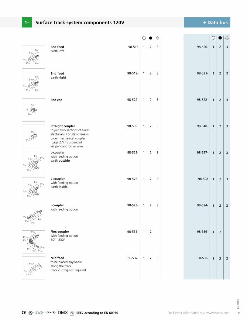
End feedearth left
L-couplerwith feeding optionearth outside
I-couplerwith feeding option
Flex-couplerwith feeding option30° - 330°
Mid feedto be placed anywhere along the tracktrack cutting not required
Straight couplerto join two sections of trackelectrically. For static reason order mechanical coupler (page 27) if suspended via pendant rod or wire
End feedearth right
L-couplerwith feeding optionearth inside
End cap
3
3
3
3
3
3
3
3
1
1
1
1
1
1
1
1
1
2
2
2
2
2
2
2
2
2
98-518
98-519-
98-522-
98-539-
98-525-
98-526-
98-523-
98-535-
98-537-
3
3
3
3
3
3
3
3
1
1
1
1
1
1
1
1
1
2
2
2
2
2
2
2
2
2
98-520-
98-521-
98-522-
98-540-
98-527-
98-528
98-524-
98-536-
98-538-
15/8“
211/16“
17/16“ 33/16“
15/16“
15/8“
211/16“
17/16“ 33/16“
15/16“
17/16“
3/32“
3/4“
17/16“15/8“
41/4“
15/16“
17/16“
33/16“
33/16“
15/8“
33/16“-
43/4“
15/16“
17/16“
15/8“
33/16“
211/16“
15/16“
17/16“
15/8“
33/16“
211/16“
15/16“
17/16“
25/8“
For further information visit www.eutrac.com
127/64“
5/16“
421/64“
R SELV according to EN 60950
32
EUTR
AC
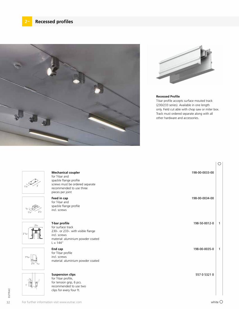
Recessed profiles2
For further information visit www.eutrac.com
Mechanical couplerfor T-bar andspackle flange profilescrews must be ordered separaterecommended to use threepieces per joint
11/8“ 3“
198-00-0033-00
Suspension clipsfor T-bar profile,for tension grip, 6 pcs.recommended to use twoclips for every four ft.
1“
3/8“
557 0 5321 0
Feed in capfor T-bar andspackle flange profileincl. screws
21/2“
153/64“
211/64“
11/8“
25/8“
25/8“
5/8“
9/16“
198-00-0034-00
T-bar profilefor surface track230-. or 233-. with visible flange incl. screwsmaterial: aluminium powder coatedL = 144“
198-50-0012-0 1
white
End capfor T-bar profileincl. screwsmaterial: aluminium powder coated
198-00-0035-0 1
Recessed ProfileT-bar profile accepts surface mouted track (230/233 series). Available in one length only. Field cut able with chop saw or miter box. Track must ordered separate along with all other hardware and accessories.
33
EUTR
AC
315/16“
115/16“
121/32“
17/8“
715/16“
157/8“
157/8“
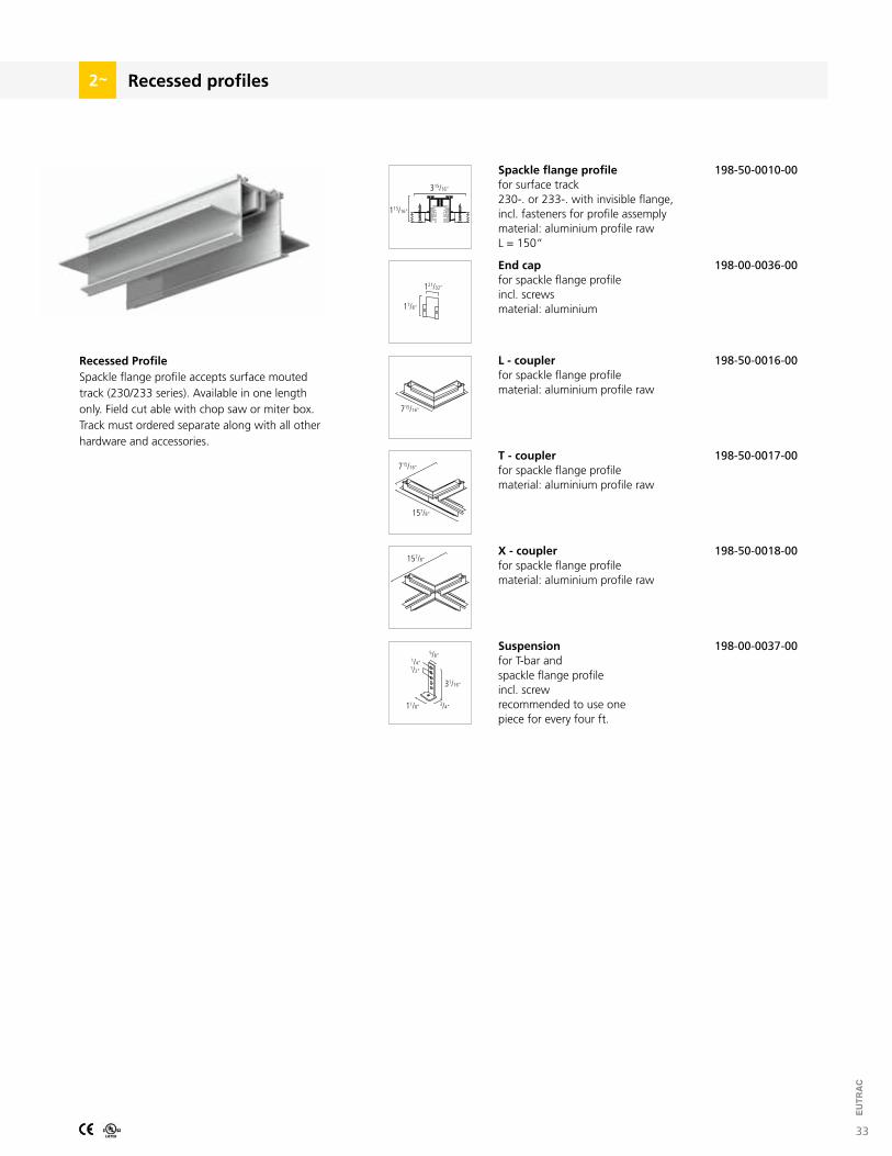
Spackle flange profilefor surface track230-. or 233-. with invisible flange, incl. fasteners for profile assemplymaterial: aluminium profile rawL = 150“
Recessed ProfileSpackle flange profile accepts surface mouted track (230/233 series). Available in one length only. Field cut able with chop saw or miter box. Track must ordered separate along with all other hardware and accessories.
198-50-0010-00
T - couplerfor spackle flange profilematerial: aluminium profile raw
L - couplerfor spackle flange profilematerial: aluminium profile raw
X - couplerfor spackle flange profilematerial: aluminium profile raw
198-50-0016-00
198-50-0017-00
198-50-0018-00
11/8“
31/16“
3/4“
5/8“
1/2“
1/4“
Suspensionfor T-bar andspackle flange profileincl. screwrecommended to use onepiece for every four ft.
198-00-0037-00
End capfor spackle flange profileincl. screwsmaterial: aluminium
198-00-0036-00
Recessed profiles2
715/16“
34
EUTR
AC
black silverwhite
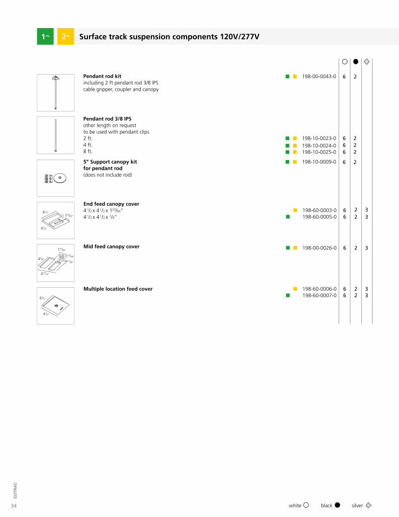
Surface track suspension components 120V/277V2
6 2
666
222
6 2
Pendant rod kitincluding 2 ft pendant rod 3/8 IPS cable gripper, coupler and canopy
Pendant rod 3/8 IPSother length on requestto be used with pendant clips2 ft.4 ft.8 ft.
5” Support canopy kitfor pendant rod(does not include rod)
198-00-0043-0
198-10-0023-0198-10-0024-0198-10-0025-0
198-10-0009-0
End feed canopy cover4 1/2 x 4 1/2 x 123/64“4 1/2 x 4 1/2 x 7/8“
Mid feed canopy cover
Multiple location feed cover
66
66
6
22
22
2
33
33
3198-00-0026-0
198-60-0006-0
198-60-0003-0198-60-0005-0
198-60-0007-0
123/64“
127/64“
117/64“
3/8“
41/2“
43/8“
41/2“
41/2“
411/16“
41/2“

35
EUTR
AC
Surface track suspension components 120V/277V2
black silverwhite
6
6
6
6
6
6
6
2
2
2
3
3
3
Pendant clipfor suspension by steel wire or pendant rod incl. lock nut 3/8 IPSmaterial: aluminium anodizedor powder coated
Mechanical couplerfor track splice, above straight coupler for suspension by steel wire or pendant rod incl. lock nut 3/8 IPSmaterial: aluminium anodizedor powder coated
198-00-0001-0
198-00-0002-0
198-00-0044-0
198-00-0041-0
198-00-0042-0
Pendant canopy and cable kitincluding aircraft cable 4‘L (48“) 1/16“ dia, canopy, cable gripper and coupler
5” Support / feed canopy kitwith pendant cable kit
5” Support canopy kitwith pendant cable kit
2” Support canopy kitwith pendant cable kit
6
6
6
198-00-0020-0
198-00-0019-0
198-00-0018-0
Pendant canopy kitincluding canopy and coupler
5” Support / feed canopy kit(does not include cable)
5” Support canopy kit(does not include cable)
2” Support canopy kit(does not include cable)
3/4“
115/16“
17/16“
3/4“
315/16“
17/16“
T-bar mounting clipfor use with 15/16” T-grid systemnut not includedmaterial: steel black
198-00-0004-0
27/8“
Pendant clipfor positioning over end feed
198-00-0038-017/16“
6“ 13/16“
Cable loop assemblycable 1/16“ dia 4 ft. 8 ft.12 ft.no cablecable 1000 ft. rollcable 3/32“ dia cable stops not incl.
198-10-0014-00198-10-0016-00
198-00-0008-00198-00-0007-00
198-10-0012-00
37
EUTR
AC
black silverwhite
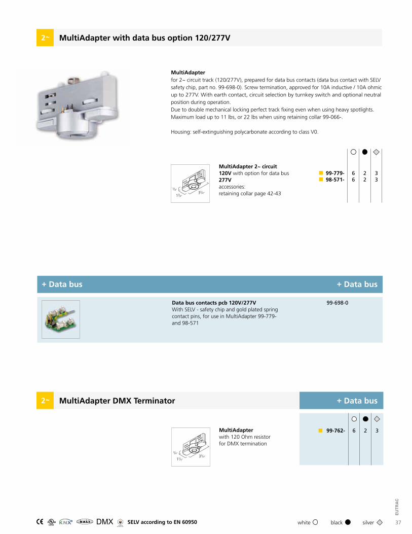
MultiAdapter with data bus option 120/277V2
MultiAdapter 2~ circuit120V with option for data bus277Vaccessories: retaining collar page 42-43
6 2 399-779-98-571-
MultiAdapterfor 2~ circuit track (120/277V), prepared for data bus contacts (data bus contact with SELV safety chip, part no. 99-698-0). Screw termination, approved for 10A inductive / 10A ohmic up to 277V. With earth contact, circuit selection by turnkey switch and optional neutral position during operation.Due to double mechanical locking perfect track fixing even when using heavy spotlights. Maximum load up to 11 lbs, or 22 lbs when using retaining collar 99-066-.
Housing: self-extinguishing polycarbonate according to class V0.
6 2 3
13/4“33/4“
3/4“
+ Data bus+ Data bus
99-698-0Data bus contacts pcb 120V/277VWith SELV - safety chip and gold plated spring contact pins, for use in MultiAdapter 99-779- and 98-571
MultiAdapter DMX Terminator2
MultiAdapterwith 120 Ohm resistorfor DMX termination
6 2 399-762-
13/4“33/4“
3/4“
+ Data bus
R SELV according to EN 60950

50
EUTR
AC
Mechanical load
Drawings below show the possible maximum load of spot lights and other devices on the 1~ and 2~ track accordingly to their mounting or suspension points. The track weight is already taken into consideration.
Important safety instructions
•
••
•
••••••
•••
•
Track is only to be used with other electrical fittings identified for use with the EUTRAC track system.To be installed by trained personnel only ( electricians ).The Installation and operation of this track system are subject to national safety regula-tions.The manufacturer is not liable for damage caused by improper use or installation. If any track system component is subsequently modified, the person responsible for the modification shall be considered as manufacturer.It is the responsibility of the installer to ensure the electrical, mechanical and thermal compatibility of the track system and the fittings.Materials used for ceiling fixation should conform to the relevant building regulations. It is essential to cover the ends of the track with end covers or protective caps.Do not install this track in damp or wet locations.Do not install any part of a track system less 5 ft. above the finish floor.Do not install this track on walls this track is only suitable for ceiling fixation.Do not install any fixture assembly closer than 6 in. from any curtain or similar combustible material.Do not slide fixtures, when changing locations then remove fixture and re-install.Disconnect electrical power before adding to or changing the configuration of the track.Do not attempt to energize anything other than lighting track fixtures on the track. In order to reduce the risk of fire and electrical shock, do not attempt to connect power tools, extension cords, appliances and the like to the track.Do not connect the track to more than the branch circuit unless the track is constructed so that it can be used with more than one branch circuit. Check with a qualified electri-cian. Although the track lighting system may seem to operate appropriately, a dangerous overload of the neutral may occur and result in a risk of fire.
Surface Track Type: 230.../ 233…/ 235…/ 238…/ 242.../ 244.../ 193.../ 293...
48”
6.6 Ibs
12” 12” 12”
6.6 Ibs 6.6 Ibs 6.6 Ibs
16” 16”
12” 12” 12”
11 Ibs 11 Ibs 11 Ibs 11 Ibs
12” 12” 12”
8“ 8“ 8“ 8“
22 lbs 22 lbs22 lbs22 lbs
51
EUTR
AC
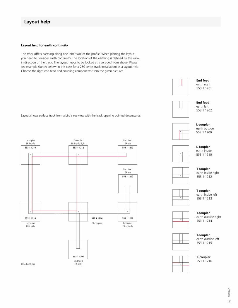
Layout help
Layout help for earth continuity
The track offers earthing along one inner side of the profile. When planing the layout you need to consider earth continuity. The location of the earthing is defined by the view in direction of the track. The layout needs to be looked at true sided from above. Please see example sketch below (in this case for a 230 series track installation) as a layout help. Choose the right end feed and coupling components from the given pictures.
Layout shows surface track from a bird´s eye view with the track opening pointed downwards.
ER = Earthing
553 1 1210 553 1 1212
553 1 1201
553 1 1202
553 1 1202
553 1 1209553 1 1210 553 1 1216
L-couplerER inside
T-couplerER inside right
End feedER left
End feedER left
L-couplerER outside
X-couplerL-couplerER inside
End feedER right
End feed earth right553 1 1201
T-couplerearth inside right553 1 1212
T-couplerearth inside left553 1 1213
T-couplerearth outside right553 1 1214
T-couplerearth outside left553 1 1215
X-coupler553 1 1216
End feed earth left553 1 1202
L-couplerearth outside553 1 1209
L-couplerearth inside553 1 1210

52
EUTR
AC
Electrical connection / wiring diagram
Installation Instruction:
Please consider all safety notes from the technical manual. Keep them carefully in case you extend or change the installation. The technical manual is also available from our web page www.eutrac.comLighting tracks are for indoor use only (IP20, 45°C max.), do not use in damp or wet locations.
a
a) Electrical connection for 120V alternating current:
maximum load: 2.400VA fuse: 20A supply cable: 3 x 12 Gauge recommended
1~ track wiring diagram
a) Electrical connection for 120V alternating current:
maximum load: 2.400VA fuse: 2 x 20A supply cable: 5 x 12 Gauge recommended
2~ track wiring diagram a
b) Electrical connection for 277V alternating current:
maximum load: 5.540VA fuse: 2 x 20A supply cable: 5 x 12 Gauge recommended
b
c) Connection diagram for data bus wiring
Attention: no closed circle structure otherwise data bus functionality will be not given.
c
d
d) Electrical connection for 120V alternating current:
maximum load: 2.400VA supply cable incl.: 2 x 12 Gauge
led-trac