lighting nest - openpicuscommunity.openpicus.com/.../files/lighting_nest_datasheet_rev2.pdf · •...
TRANSCRIPT

www.openpicus.com LIGHTING NEST Datasheet rev.2 24.04.2012 Page
1
• FLYPORT expansion board for
lights/loads control over Internet
• Compatible with FLYPORT Ethernet and FLYPORT Wi-Fi • 4 Relays
• 1 Triac (On/Off, AC only)
• 2 opto-isolated inputs
• Compatible with miniUSB
Programmer for firmware download
• Optional RJ45 connector
• 5V Power Supply
• 131*57 mm (15 gr)
LIGHTING NEST Expansion board
Introduction
Features
Power Supply 5V external power supply (J3 connector) (6V Max via Ethernet cable as option)
Outputs 4 Relays and 1 TRIAC
Inputs 2 opto-isolated Compatible with FLYPORT Wi-Fi, FLYPORT Ethernet (Conn.J1 and J2)
Programmer
6 ways miniUSB PROG connector onboard
Connector pin J1,J2 : 26 ways female pin headers SAMTEC ssw-113-01-t-d or FCI 65781-013) J4 : RJ45 (optional) PULSE J0006D21NL (no led)
Dimensions 130.66 x 56.60 mm, 15 grams
• Turn on/off devices over Internet • Lights control over IP • Irrigation system control over
Internet • Open/close gates and doors • Home remote control • Industrial/process control
Applications
LIGHTING NEST is a general purtpose control expansion board for the FLYPORT Wi-Fi and FLYPORT Ethernet modules. LIGHTING NEST provides 4 relays output (5A max), a opto-isolated zero-crossing TRIAC controlled 220Vac (1A max), 2 opto-isolated inputs The power supply can be provided with an external 5 V source. The expansion board is fully compatible with the ‘miniUSB for the firmware download to FLYPORT modules. It is possible to use the FLYPORT Ethernet without RJ45 connector: the RJ45 connector can be soldered on J4. LIGHTING NEST fits the NEST Box (HAMMOND 1593XBK plastic enclosure box).

www.openpicus.com LIGHTING NEST Datasheet rev.2 24.04.2012 Page
2
Connectors PINOUT
The LIGHTING NEST provides connections to 4 relays, 1 TRIAC and 2 opto-isolated inputs. J1 and J2 are compatible with Flyport Wi-Fi and Flyport Ethernet modules. J6 is a 2x5 pins 2.54mm pitch (0.10”) general purpose expansion connector. The relay outputs are on J7, the TRIAC output is on J1, the opto-isolated inputs are on J3 and J4. JM1 and JM2 jumpers let configure the input type (dry contact or 5-10 V input)
Power Connectors
J7 – Relays
Pin Function FLYPORT connector J1 pin
1—2 Relay1 NO 6
3—4 Relay2 NO 17
5—6 Relay3 NO 19
7—8 Relay4 NO 21
Relays are activated by FLYPORT digital output pins (active high)
J1- Triac
Pin Default name FLYPORT connector J1 pin
1—2 Triac switch 4
www.openpicus.com LIGHTING NEST Datasheet rev.2 24.04.2012 Page
3
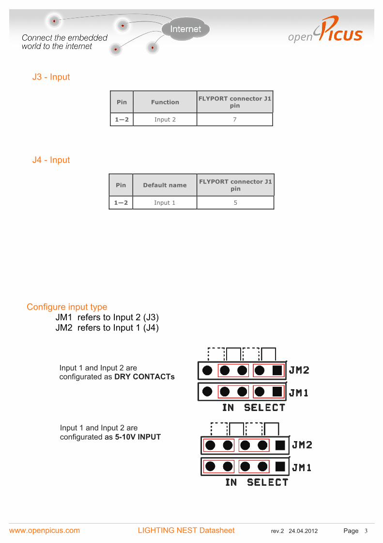
J3 - Input
Pin Function FLYPORT connector J1 pin
1—2 Input 2 7
J4 - Input
Pin Default name FLYPORT connector J1 pin
1—2 Input 1 5
Configure input type
JM1 refers to Input 2 (J3) JM2 refers to Input 1 (J4)
Input 1 and Input 2 are configurated as 5-10V INPUT
Input 1 and Input 2 are configurated as DRY CONTACTs
www.openpicus.com LIGHTING NEST Datasheet rev.2 24.04.2012 Page
4
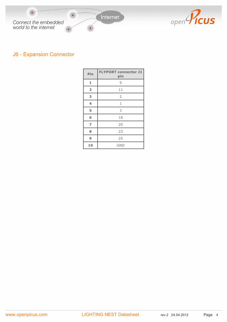
J6 - Expansion Connector
Pin FLYPORT connector J1 pin
1 9
2 11
3 2
4 1
5 3
6 18
7 20
8 23
9 25
10 GND
www.openpicus.com LIGHTING NEST Datasheet rev.2 24.04.2012 Page
5
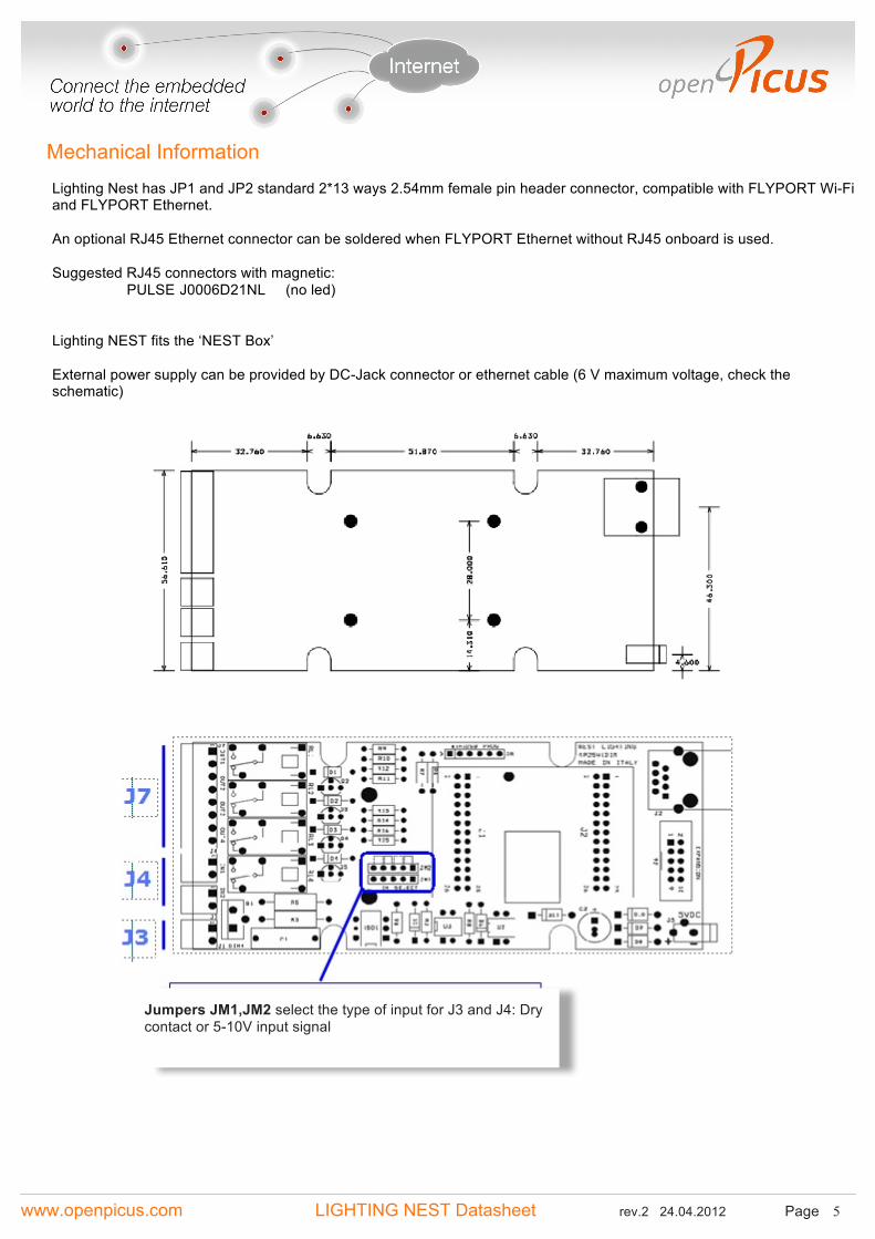
Mechanical Information
Lighting Nest has JP1 and JP2 standard 2*13 ways 2.54mm female pin header connector, compatible with FLYPORT Wi-Fi and FLYPORT Ethernet. An optional RJ45 Ethernet connector can be soldered when FLYPORT Ethernet without RJ45 onboard is used. Suggested RJ45 connectors with magnetic: PULSE J0006D21NL (no led) Lighting NEST fits the ‘NEST Box’ External power supply can be provided by DC-Jack connector or ethernet cable (6 V maximum voltage, check the schematic)
Jumpers JM1,JM2 select the type of input for J3 and J4: Dry contact or 5-10V input signal

www.openpicus.com LIGHTING NEST Datasheet rev.2 24.04.2012 Page
6
Power supply 5V Relays 5A max TRIAC 220Vac 1A max Inputs (opto-isolated) dry contact or 5-10V
Operating Temperature -20..+85°C Dimensions 131*57*25mm
Technical Information
Electrical Inputs & Outputs
Mechanical

www.openpicus.com LIGHTING NEST Datasheet rev.2 24.04.2012 Page
7
Ordering information
Buy online from our store or through our resellers and distributors.
Code 015375 LIGHTING NEST - no the RJ45 connector onboard
How to start development Visit our website www.openpicus.com to download the IDE, a getting started guide and application notes, examples and libraries. The suggested starter kit is composed by:
• miniUSB PROGRAMMER (to download firmware) Code.015371 • LIGHTING NEST Code.015375 • FLYPORT Wi-Fi module Code.015350 or Code.015353 OR • FLYPORT Ethernet module Code.015356 or Code.015357
Each FLYPORT module has a serial bootloader onboard.