light transmission and interferometry in liquid-liquid waveguide for photocatalytic ...€¦ ·...
TRANSCRIPT

LIGHT TRANSMISSION AND INTERFEROMETERY IN LIQUID-LIQUID WAVEGUIDE FOR PHOTOCATALYTIC APPLICATIONS
Y. Yang1, G. P. Wang2 and A. Q. Liu1*
1School of Electrical and Electronic Engineering, Nanyang Technological University, Singapore 639798 2Department of Physics, Wuhan University, Wuhan 430072, P. R. China
ABSTRACT
This paper report the first experimental findings of the unique focusing and interference phenomena in the optofluidic waveguide formed by miscible laminar flows, which cannot be seen in solid waveguides. In the optofluidic waveguide, diffusion creates refractive index gradients in both transverse and longitudinal directions. This bi-directional gradient-index profile is an exceptional trait of optofluidic waveguide and the key to the distinct focusing and interference effects. We believe that this work brings fresh insight into the uniqueness of optofluidic waveguide and will open new doors in photocatalytic green energy and pollution reduction for chemistry and life sciences. KEYWORDS: Liquid waveguide, Optofluidic, Diffusion, Photocatalytic
INTRODUCTION
Optofluidics utilizes optics and microfluidics to create miniaturized systems for chemistry and life sciences [1, 2]. It has inspired the creation of a variety of innovative devices. Among them, liquid waveguides have attracted a lot of interests because their optical properties can be tuned in a large range by manipulating flow rate and liquid compositions [3, 4], which are not possible for solid-material based waveguides [5]. A pure liquid waveguide typically consists of three laminar flows, one with higher refractive index as the core fluid and the other two with lower refractive index as the cladding fluids. Many studies attempted to use the liquid waveguides the same way as the solid waveguides, for example, the liquid waveguides using immiscible liquids work like the step-index solid waveguides. However, the fluidic form of the liquid waveguide are more flexibility. For instance, gradient-index optofluidic waveguides could be created using miscible liquids without much difficulty. This unique property and full potential of liquid waveguides has not yet to explore. Here, we recognize liquid waveguides using miscible liquids by increasing diffusion between the liquids when they flow forward, and making refractive index gradients in both transverse and longitudinal directions because of the diffusion and convection of the liquids. This bi-directional refractive index gradient profile causes the rays to focus and interfere in the liquid waveguides. As the bi-directional profile is a unique feature of the liquid waveguides and cannot be realized easily using solid-material, the transmission and interference effect is unique to the liquid waveguides. We believe that this work brings fresh insight into the uniqueness of optofluidic waveguide and will open new doors in photocatalytic green energy and pollution reduction for chemistry and life sciences [6].
WORKING PRINCIPLE AND SIMULATION RESULTS
Figure 1 shows the working principle of the diffusion-induced bi-directional gradient-index liquid waveguide. The liquid waveguide consists of three laminar flows in the microchannel. The core liquid has a refractive index higher than the cladding liquid. The two liquids are miscible and can diffuse to each other. In Fig. 1(a), step-index profile is establish when the three flow streams are injected at high flow rate. At low flow rate, the diffusion occurs at the interfaces of core/cladding to smear as the fluids move down, causing a unique bidirectional gradient-index in the microchannel (Fig. 1(b)).
Figure 1: Schematic illustration of the diffusion-induced bi-directional gradient-index liquid waveguide. (a) Step-index profile of the microchannel when the core fluid is injected at high flow rate. (b) Gradient refractive index distribution due to the diffusion occurs at low flow rate. This gradient index is bi-directional and unique in microfluidics.
1.34
1.42 b
a
H = 100
W = 150 m
r/2
L = 2500 m
978-0-9798064-4-5/µTAS 2011/$20©11CBMS-0001 1272 15th International Conference onMiniaturized Systems for Chemistry and Life Sciences
October 2-6, 2011, Seattle, Washington, USA
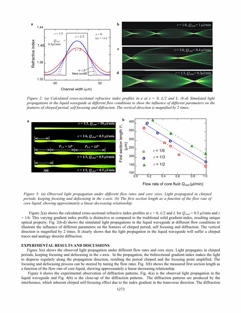
Figure 3: (a) Observed light propagation under different flow rates and core sizes. Light propagated in chirped periods, keeping focusing and defocusing in the x-axis. (b) The first section length as a function of the flow rate of core liquid, showing approximately a linear decreasing relationship.
a
300
r = 1/3, Qclad = 50 l/min
r = 1/2, Qclad = 0.5 l/min
r = 1/3, Qclad = 0.5 l/min
r = 1/6, Qclad = 0.5 l/min
b
0.0 0.4 0.8 1.0
Flow rate of core fluid Qclad (µl/min)
0.2 0.6
Firs
t sec
tion
leng
th P
1 (
m)
r = 1/6
r = 1/3
100
150
200
250
300
350
400
r = 1/2
P1/3 + P P1/3 + P
Figure 2(a) shows the calculated cross-sectional refractive index profiles at x = 0, L/2 and L for Qclad = 0.5 l/min and r = 1/6. This varying gradient index profile is distinctive as compared to the traditional solid gradient-index, resulting unique optical property. Fig. 2(b-d) shows the simulated light propagations in the liquid waveguide at different flow conditions to illustrate the influence of different parameters on the features of chirped period, self focusing and diffraction. The vertical direction is magnified by 2 times. It clearly shows that the light propagation in the liquid waveguide will suffer a chirped traces and analogy discrete diffraction. EXPERIMENTAL RESULTS AND DISCUSSIONS
Figure 3(a) shows the observed light propagation under different flow rates and core sizes. Light propagates in chirped periods, keeping focusing and defocusing in the x-axis. In the propagation, the bidirectional gradient-index makes the light to disperse regularly along the propagation direction, resulting the period chirped and the focusing point amplified. The focusing and defocusing process can be steered by tuning the flow rates. Fig. 3(b) shows the measured first section length as a function of the flow rate of core liquid, showing approximately a linear decreasing relationship.
Figure 4 shows the experimental observation of diffraction patterns. Fig. 4(a) is the observed light propagation in the liquid waveguide and Fig. 4(b) is the close-up of the diffraction patterns. The diffraction patterns are produced by the interference, which inherent chirped self-focusing effect due to the index gradient in the transverse direction. The diffraction
Figure 2: (a) Calculated cross-sectional refractive index profiles in c at x = 0, L/2 and L. (b-d) Simulated light propagations in the liquid waveguide at different flow conditions to show the influence of different parameters on the features of chirped period, self focusing and diffraction. The vertical direction is magnified by 2 times.
Channel width (m)
-50 50
Ref
ract
ive
inde
x x = 0 ( = +) x = L/2
x = L
1.32
1.36
1.40
1.44
= 2 fitted curves
r = 1/3
Qclad = 0.5l/min
a b
c
d
r = 1/6, Qclad = 1 l/min
r = 1/6, Qclad = 0.4 l/min
r = 1/3, Qclad = 0.3l/min
1273

a r = 1/3, Qclad = 0.5 l/min b
c
Channel width (µm)
Nor
mal
ized
inte
nsity
0 8 16 -16 -8
0.8
Channel length (µm)
0.0
0.2
0.4
0.6
6030 7515 45 0
1st section2nd section3rd section
1.0
100
Inte
nsity
(a.
u.)
Figure 4: Experimental observation of diffraction patterns. (a)Observed light propagation in the optofluidic waveguide. (b) Close-up of the diffraction patterns. (c) Intensity profiles along the central line for the first three sections. It shows that the diffraction pattern vary with the sequence number of the section. (d) Comparison of the intensity profiles along the monitoring lines 1 and 2 in the measured (solid lines) and simulated (dotted lines) diffraction patterns.
patterns vary with their positions and can be easily tuned over a large range by changing the fluids or light characteristics. Fig. 4(c) is the intensity profiles along the central line for the first three sections. It shows that the diffraction pattern vary with the sequence number of the section. Fig. 4(d) is the comparison of the intensity profiles along the monitoring lines 1 and 2 in the measured (solid lines) and simulated (dotted lines) diffraction patterns. CONCLUSIONS
In conclusion, we have experimentally steered light propagation with the features of self focusing, chirped period and diffraction in bidirectional gradient-index liquid waveguides. With inherent real-time tunability and reconfigurability, the gradient-index liquid waveguides would provide a flexible and versatile platform for many scientific studies and application such as photocatalysis for renewable energy. ACKNOWLEDGEMENT
This work is supported by research project that was funded by the Environmental & Water Industry Development Council of Singapore (MEWR C651/06/171). REFERENCES [1] D. Psaltis, S. R. Quake and C. H. Yang, “Developing optofluidic technology through the fusion of microfluidics and
optics,” Nature, 442, 381–386 (2006). [2] C.Monat, P. Domachuk and B. J. Eggleton, “Integrated optofluidics: A new river of light,” Nature Photon., 1, 106 –
114 (2007). [3] D. B. Wolfe, R. S. Conroy, P. Garstecki, B. T. Mayers, M. A. Fischbach, K. E. Paul, M. Prentiss and G. M. Whitesides,
“Dynamic control of liquid-core/liquid-cladding optical waveguides,” PNAS, 101, 12434 – 12438 (2004). [4] Y. Yang, A. Q. Liu, L. Lei, L. K. Chin, C. D. Ohl, Q. J. Wang and H. S. Yoon, “A tunable 3D optofluidic waveguide
dye laser via two centrifugal Dean flow streams,” Lab Chip, in press (2011). [5] A. W. Synder and J. D. Love, “Optical Waveguide Theory,” Institute of Advanced Studies, Australian National
University (1983). [6] J. C. S. Wu, T. H. Wu, T. Chu, H. Huang and D. P. Tsai, “Application of optical-fiber photoreactor for CO2
photocatalytic reduction,” Top Catal., 47, 131 – 136 (2008). CONTACT *A. Q. Liu, Tel: +65-6790 4336; Fax: +65-6793 3318; Email: [email protected]
1274