light-trains: an integrated optical-wireless solution for high
TRANSCRIPT
INFOCOMMUNICATIONS JOURNAL
FEBRUARY 2011 • VOLUME III • NUMBER 1 1
Light-trains: An Integrated Optical-Wireless Solution forHigh Bandwidth Applications in High-Speed Metro-Trains
Light-trains: An Integrated Optical-Wireless Solution for High Bandwidth Applications in High-Speed Metro-Trains
(Invited Paper)
Ashwin Gumaste, Akhil Lodha, Saurabh Mehta, Jianping Wang and Nasir Ghani
Abstract: Moving trains represent a voluminous mass of users moving at high velocities that require bandwidth (on demand). A new solution is proposed that facilitates dynamic provisioning, good scalability and efficient use of available bandwidth. The proposed solution (light-trains) seamlessly integrates optical and wireless networking to provide broadband access to users in moving trains. The solution identifies the set of requirements – such as fast hand-off, low-cost of deployment, mature technology and ability to provide dynamic bandwidth provisioning. A protocol that enables end-to-end provisioning across the three domains of technology aka light-trails, WiMax and WiFi is also proposed. The proposed protocol is a cornerstone mechanism for providing inter-domain (technology) connectivity in a pragmatic way. Different aspects of the protocol are considered, amongst which delay and efficiency are analyzed and computed. The protocol and system requirements juxtaposed are simulated extensively. Results pertaining to utilization, delay, efficiency and network wide performance are all showcased. Viability of the model in being able to provide bandwidth to moving users is shown.
Key words: light-trails, moving trains, bandwidth-on-demand, cross medium communications.
I. INTRODUCTION
The growth and spread of the Internet and other web services into the wireless domain has facilitated ubiquity and mobility for end-users. A significant number of the end-users that make use of bandwidth intensive applications are in mass-transportation systems. In order to provide bandwidth to users within the domain of a mass transportation system, it is imperative to have a wireless access mechanism that is further bolstered by a high-speed and dynamic wired backbone solution.
Manuscript received February 6, 2011. A. Gumaste is James R. Isaac Chair and faculty member in the Department of Computer Science and Engineering, Indian Institute of Technology (IIT), Bombay 400076, India. Akhil Lodha is Quantative Analyst on the Electronic Options Trading desk at Citigroup, New York. S. Mehta is a research scholear with the Department of Computer Science and Engineering, Indian Institute of Technology (IIT), Bombay, India. Jianping Wang is an assistant professor in the Department of Computer Science at City University of Hong Kong. Nasir Ghani is with the University of New Mexico (UNM), Albuquerque, NM87131 USA. Digital Object Identifier:
The metro train represents a popular form of mass-transportation system in either its underground or over-bridge manifestation. (1) There are a large number of bandwidth hungry users within the confinement of a metro train. (2) Such a train represents a single moving entity that requires dynamic bandwidth allocation as it moves through a wireless network. (3) Further, several trains can statistically co-exist on the same track. This makes the bandwidth allocation problem along a track complex in lieu of the limited bandwidth-distance product offered by wireless. These needs imply added levels of complexity in the design of hand-off mechanisms and in provisioning the underlying “core” network to facilitate multimedia and emerging broadband applications. We propose a mechanism that enables bandwidth-on-demand to trains over a cross-medium architecture comprising of a wireless overlay supported by a metro-core optical network.
End-users within the train receive and transmit data from access points in each coach, and hence are part of a wireless LAN (IEEE 802.11 type). The access points are further connected to an Ethernet aggregation switch in the train. Provisioning the underlying physical layer which is typically an optical network taking into cognizance this moving entity poses a new design problem.
The light-train approach combines the wireless and optical layers to create an efficient solution for bandwidth allocation in trains. To do so, the light-train solution uses a novel optical technology used in conjunction with wireless end-user technologies. The approach proposed by us takes into consideration end-user profile from both a service requirement as well as equipment asset perspective. The protocol proposed ensures seamless ubiquity while adhering to the norms set by emerging networking services. Our approach has practical assumptions – there is no need to upgrade equipment at the end-users (who continue to use well-disseminated WiFi technology). Equipment is only upgraded at the network side.
This work is an extension of [12] – where we proposed the concept of bandwidth to moving trains. This work further enhances that concept providing a detailed stochastic model in addition to rigorous simulations. We propose the light-trains model as an engineering solution for providing bandwidth on demand to moving trains. In Section II, we discuss the system design of the light-trains model. Section III showcases how the legacy IP network reacts/interfaces to our light-train model. Section IV discusses the principles of the proposed integrated protocol. Section V provides for delay analysis. Section VI compares our model to other related works. Section VII discusses simulation results while Section VIII summarizes the paper.

INFOCOMMUNICATIONS JOURNAL
2 FEBRUARY 2011 • VOLUME III • NUMBER 1
Fig. 1. Conceptual layout of metro trains over a wireless network and underlying optical network.
II. LIGHT-TRAIN SYSTEM AND DEFINITIONS
Consider a train u moving along a track. The system is as shown in Fig. 1. Wireless Gateways: As the train u travels, it communicates with the rest of the core network through wireless gateways(GW) situated at intervals along the track. The gateways have a limited transmission range and a series of gateways provide bandwidth to a moving train in a concept that is similar to cellular communications. Gateways are positioned one after another separated by a distance that is computed by the transmission range (to prevent Signal-to-Noise Ratio – SNR from degrading below a certain threshold). The distance of coverage of a particular wireless gateway is defined as the geographic range of that gateway. In addition to geographic range, we define the concept of provisioning zone as the overlap area between the geographic ranges of two adjacent GWs. Trains move from one GW to another in a seamless manner thus maintaining ubiquitous communication. Power based hand-off is the typical technique used for maintaining ubiquity. Hand-off occurs in the provisioning zones. Hand-off and associated methods are defined and explained subsequently in Section IV. B.
The principle requirement on the optical network is of dynamic provisioning of bandwidth to wireless GWs. Data paths must be provisioned to the wireless GWs through the optical network on an on-demand basis to meet the BW and delay constraints of services. This time-sensitive requirement, coupled with the fact that multiple trains will be sharing the same track, implies that pre-provisioning will generally lead to an inefficient bandwidth solution. To enable ubiquity it is necessary that the combined optical + wireless network be able to provide fast hand-off.
For example cellular hand-off solutions require up to several 100s of milliseconds. Similarly concepts based on moving tunnel approach as shown in [8] require up to 100 milliseconds.
We propose an optically-assisted method for hand-off. The underlying principle utilizes the dual concepts of optical multicasting and out-of-band control (described later).
Another characteristic for cross-medium integration is signaling: wireless GWs must be able to signal to each other
about ongoing communication activities when trains move through their geographic range.
To illustrate this, consider the example of a train that moves through the geographic range of one GW to the next (adjacent) GW. Assume that a user in the train is trying to download a large file. Assume that the time required to download the file exceeds the geographic range of the GW; and hence it cannot be downloaded within the range of one GW. In such a case, the file must be made available to the next adjacent GW, when the train arrives in its geographic range, so that the user in the train can successfully download the entire file. The time lost between tearing down the connection between the train and the first GW and the setting up the connection (making the file available) at the second GW is of critical importance. Another factor that also leads to an efficient cross-medium solution is that the second GW must be aware of the fraction of the file that was successfully transmitted by the first GW, so that it has to only transmit the remaining fraction. While TCP sequencing would take care of this issue, we do require a more robust and far more dynamically adjustable solution. This necessitates the need for efficient signaling both at the optical and the wireless layer amongst nodes as well as between the nodes and the train.
An optical networking solution that enables dynamic provisioning, optical multicasting and provides for effective signaling is the light-trails approach originally proposed in [1-4]. As opposed to conventional end-to-end circuit or lightpath (optical wavelength circuit), a light-trail is a generalization of a lightpath [5] such that multiple nodes along the path can communicate with each other. A light-trail is analogous to an optical bus with the added advantage that communication and arbitration of the bus is done through an out-of-band (OOB) control channel. The OOB control channel is optically dropped, electronically processed and then reinserted into the network. The differentiation between the OEO control channel and the all-optical (OOO) bus based data channel is the key to some of the functionalities of light-trail based networks. Multiple light-trails, each on a unique wavelength, use a common control channel.
In order to create a light-trail, nodes must be based on an architecture that supports three functionalities: (1) The ability to drop-and-continue incoming optical signal. (2) Ability to passively add optical signal and (3) To support the OOB control. The first two properties, that of drop and continue as well as passive addition lead to formation of the optical bus, while the third property enables efficient (dynamic) provisioning within the bus. A light-trail is defined between two extreme nodes (a start node called the convener node and a stop node called end-node) that regulate signal flow within the optical wavelength bus. Signal flow is in the direction from the convener to the end-node.
Light-trail node architecture is shown in Fig. 2. A fiber that carries composite WDM signal enters the node premises from the left-side. The composite signal is de-multiplexed into constituent wavelengths by an optical de-multiplexer (typically an Arrayed Wave-Guide – AWG). The
Light-trail node
Metro train
WiMax BS Optical access line (underlying network)
IP router Range of the wireless channel
Fiber
Light-trains: An Integrated Optical-Wireless Solution forHigh Bandwidth Applications in High-Speed Metro-Trains

INFOCOMMUNICATIONS JOURNAL
FEBRUARY 2011 • VOLUME III • NUMBER 1 3
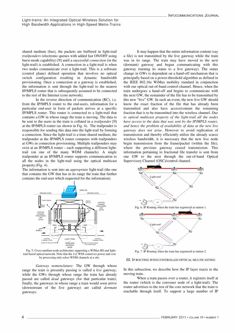
control channel is also extracted and electronically processed by a control card. The data channels that are de-multiplexed are fed individually to a local access section. This section enables the node to access (TX/RX) data on individual light-trails. To do so, the section consists of two passive couplers separated by an optical shutter. The two couplers are in 1x2 and 2x1 configurations. The first coupler (called Drop Coupler – DC) drops and continues incoming optical signal while the second coupler (called Add Coupler – AC) enables passive addition of the optical signal. The optical shutter is a slow moving switch that is in the OFF position at the convener and end-nodes of a light-trail, while is in the ON position for all the intermediate nodes. Switching is required only when light-trails are set up or torn down, which for the case of providing bandwidth to moving trains is a semi-permanent feature and seldom used.
Nodes along a light-trail communicate with each other by setting up connections. Connection setup and tear-down over a light-trail requires no optical switching and is done entirely through signaling in the OOB control channel using a protocol that we define in Section III.
Fig. 2. Light-trail node specifics.
II. A. High Level System Description: An IP/MPLS backbone network interacts with the
railway-grid at select gateways to provide backbone connectivity with the rest of the Internet. Typically, the selection of IP/MPLS routers along the grid implies points at which a light-trail terminates or commences as shown in the Fig. 3. Each gateway communicates with a passing train through a wireless link.
We propose WiMax as a wireless candidate technology for the wireless link between a GW and a moving train. The choice of IEEE 802.16 WiMax is due to the support of the large distance-bandwidth product and ability to coexist with other wireless last inch technologies that users may in addition subscribe to (for e.g. cellular/GSM or WiFI).
Co m3
Fig. 3 Connection establishment in light-trains.
Information sent by the GW to the train is collected at a single platform within the train (the WiMax SS). This platform has a dual role: in one direction of communication it is used for communicating with the GW and in the other direction of communication it acts as an Access Point (AP) used to communicate with the end-users (residing in the train). II. B: Duplex Communication in the Light-train System:
Let us now consider how a real-time application is supported at an end-user. A duplex communication application operates through our system using two communication modes – Forward Communication (FC) and Reverse Communication (RC) depending on the direction of communication from or tothe end-user. We first describe how FC works. The application at the end-user sends information through the intra-train WiFi network to the access point. In our model, we assume that the WiFi network is configured to implement PCF mode of operation, so as to enhance throughput.
The AP/SS collects this data (in form of Ethernet frames) and attempts to send it to a gateway through whose geographic range the train is passing. A scheduling protocol in the WiMax domain and a fast hand-off mechanism is assumed (and described in Section IV.B) that enables establishment of communication and ubiquity between the SS and the GW. The WiMax frequency allocation is described in Section IV. The railway tracks are assumed to be divided into cells in succession, that are partially overlapped power-threshold defined regions supporting wireless communication. When a train passes from the range of one cell to another cell, a hard hand-off is assumed to happen.
Fig. 4. Light-trail architecture : Data collection at the trailponder.
The packets that are sent to the GW, should now be transported into the core network. This is done by the optical (light-trail) solution. Since a light-trail is an all-optical time-
Light-trains: An Integrated Optical-Wireless Solution forHigh Bandwidth Applications in High-Speed Metro-Trains
INFOCOMMUNICATIONS JOURNAL
4 FEBRUARY 2011 • VOLUME III • NUMBER 1
shared medium (bus), the packets are buffered in light-trail trailponders (electronic queues with added fast ON/OFF using burst-mode capability) [9] until a successful connection (in the light-trail) is established. A connection in a light-trail is when two nodes communicate over a light-trail. This is a software (control plane) defined operation that involves no optical switch configuration resulting in dynamic bandwidth provisioning. Once a connection at a gateway is established, the information is sent through the light-trail to the nearest IP/MPLS router that is subsequently assumed to be connected to the rest of the Internet (core network).
In the reverse direction of communication (RC), i.e. from the IP/MPLS router to the end-users, information for a particular end-user in form of packets arrives at a specific IP/MPLS router. This router is connected to a light-trail that contains a GW in whose range the train is moving. The data to be sent to the users in the train is collated in a trailponder [9] at the IP/MPLS router (as shown in Fig. 4). The trailponder is responsible for sending this data into the light-trail by forming a connection. Since the light-trail is a time-shared medium, the trailponder at the IP/MPLS router competes with trailponders at GWs in connection provisioning. Multiple trailponders may exist at an IP/MPLS router – each supporting a different light-trail (on one of the many WDM channels). A single trailponder at an IP/MPLS router supports communication to all the nodes in the light-trail using the optical multicast property.(Fig. 4). The information is sent into an appropriate light-trail (the one that contains the GW that has in its range the train that further contains the end-user which requested for the information).
OSC
CARD
DIGITALSWITCH
BUFFERSET
LIGHT-TRAIL+
WIRELESSGATEWAY
NODE
CONTROLCHANNEL FIlTER
CONTROLCHANNEL
PROCESSINGUNIT
(CCPU)
OSC
CARD
CONTROLCHANNEL FIlTER
WiMAX BS
Coupler for passive addingof the optical signal
Coupler for drop and continue
2x1WSS1x2 WSS
AWG AWG
GROUND LEVEL GROUND LEVEL
CONTROLCHANNEL
PROCESSINGUNIT
(CCPU)
BUBBLE
TRAILPONDER
BMTX/BMRX
Fig. 5. Cross-medium node architecture supporting a WiMax BS and light-trail based optical network. Note that the 1x2 WSS conserves power and cost
by processing only select WDM channels at a site.
Gateway nomenclature: The GW through whose range the train is presently passing is called a live gateway; while the GWs through whose range the train has already passed are called dead gateways (for that particular train); finally, the gateways in whose range a train would soon arrive (downstream of the live gateway) are called dormantgateways.
It may happen that the entire information content (say a file) is not transmitted by the live gateway while the train was in its range. The train may have moved to the next (dormant) gateway and begun communicating with this gateway (turning its status to a live gateway). The status change in GWs is dependent on a hand-off mechanism that is principally based on a power-threshold algorithm as defined in the IEEE 802.16e WiMax mobility standard in conjunction with our optical out-of-band control-channel. Hence, when the train undergoes a hand-off and begins to communicate with the next GW, the remainder of the file has to be transmitted by this new “live” GW. In such an event, the new live GW should know the exact fraction of the file that has already been transmitted and also have access/contain the remaining fraction that is to be transmitted into the wireless channel. Due to optical multicast property of the light-trail all the nodes have access to the data that was sent by the IP/MPLS router, and hence the problem of availability of data at the new live gateway does not arise. However to avoid replication of transmission and thereby efficiently utilize the already scarce wireless bandwidth, it is necessary that the new live node begin transmission from the frame/packet (within the file), where the previous gateway ceased transmission. This information pertaining to fractional file transfer is sent from one GW to the next through the out-of-band Optical Supervisory Channel (OSC)/control channel.
Fig. 6. IP Routing when the train has registered at station 1.
Fig. 7. IP Routing when the train has registered at station 2.
III. IP ROUTING WITH CONTROLLED OPTICAL MULTICASTING
In this subsection, we describe how the IP layer reacts to the moving train.
When a train passes over a router, it registers itself at the router (which is the convener node of a light-trail). The router advertises to the rest of the core network that the train is reachable through itself. To support a large number of IP
Light-trail
Light-trail
Light-trains: An Integrated Optical-Wireless Solution forHigh Bandwidth Applications in High-Speed Metro-Trains
INFOCOMMUNICATIONS JOURNAL
FEBRUARY 2011 • VOLUME III • NUMBER 1 5
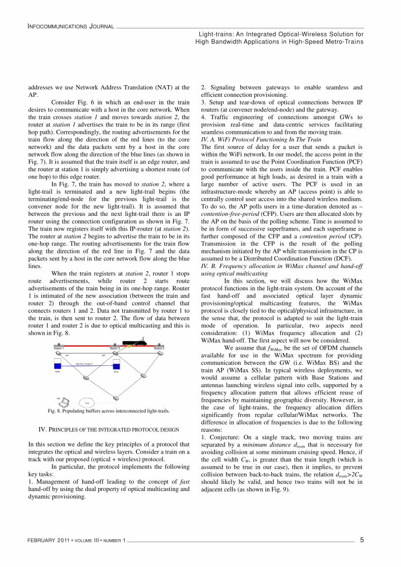
addresses we use Network Address Translation (NAT) at the AP.
Consider Fig. 6 in which an end-user in the train desires to communicate with a host in the core network. When the train crosses station 1 and moves towards station 2, the router at station 1 advertises the train to be in its range (first hop path). Correspondingly, the routing advertisements for the train flow along the direction of the red lines (to the core network) and the data packets sent by a host in the core network flow along the direction of the blue lines (as shown in Fig. 7). It is assumed that the train itself is an edge router, and the router at station 1 is simply advertising a shortest route (of one hop) to this edge router.
In Fig. 7, the train has moved to station 2, where a light-trail is terminated and a new light-trail begins (the terminating/end-node for the previous light-trail is the convener node for the new light-trail). It is assumed that between the previous and the next light-trail there is an IP router using the connection configuration as shown in Fig. 7. The train now registers itself with this IP-router (at station 2).The router at station 2 begins to advertise the train to be in its one-hop range. The routing advertisements for the train flow along the direction of the red line in Fig. 7 and the data packets sent by a host in the core network flow along the blue lines.
When the train registers at station 2, router 1 stops route advertisements, while router 2 starts route advertisements of the train being in its one-hop range. Router 1 is intimated of the new association (between the train and router 2) through the out-of-band control channel that connects routers 1 and 2. Data not transmitted by router 1 to the train, is then sent to router 2. The flow of data between router 1 and router 2 is due to optical multicasting and this is shown in Fig. 8.
Fig. 8. Populating buffers across interconnected light-trails.
IV. PRINCIPLES OF THE INTEGRATED PROTOCOL DESIGN
In this section we define the key principles of a protocol that integrates the optical and wireless layers. Consider a train on a track with our proposed (optical + wireless) protocol.
In particular, the protocol implements the following key tasks: 1. Management of hand-off leading to the concept of fasthand-off by using the dual property of optical multicasting and dynamic provisioning.
2. Signaling between gateways to enable seamless and efficient connection provisioning. 3. Setup and tear-down of optical connections between IP routers (at convener node/end-node) and the gateway. 4. Traffic engineering of connections amongst GWs to provision real-time and data-centric services facilitating seamless communication to and from the moving train. IV. A. WiFi Protocol Functioning In The Train The first source of delay for a user that sends a packet is within the WiFi network. In our model, the access point in the train is assumed to use the Point Coordination Function (PCF) to communicate with the users inside the train. PCF enables good performance at high loads, as desired in a train with a large number of active users. The PCF is used in an infrastructure-mode whereby an AP (access point) is able to centrally control user access into the shared wireless medium. To do so, the AP polls users in a time-duration denoted as – contention-free-period (CFP). Users are then allocated slots by the AP on the basis of the polling scheme. Time is assumed to be in form of successive superframes, and each superframe is further composed of the CFP and a contention period (CP). Transmission in the CFP is the result of the polling mechanism initiated by the AP while transmission in the CP is assumed to be a Distributed Coordination Function (DCF). IV. B. Frequency allocation in WiMax channel and hand-off using optical multicasting
In this section, we will discuss how the WiMax protocol functions in the light-train system. On account of the fast hand-off and associated optical layer dynamic provisioning/optical multicasting features, the WiMax protocol is closely tied to the optical/physical infrastructure, in the sense that, the protocol is adapted to suit the light-train mode of operation. In particular, two aspects need consideration: (1) WiMax frequency allocation and (2) WiMax hand-off. The first aspect will now be considered.
We assume that fWiMax be the set of OFDM channels available for use in the WiMax spectrum for providing communication between the GW (i.e. WiMax BS) and the train AP (WiMax SS). In typical wireless deployments, we would assume a cellular pattern with Base Stations and antennas launching wireless signal into cells, supported by a frequency allocation pattern that allows efficient reuse of frequencies by maintaining geographic diversity. However, in the case of light-trains, the frequency allocation differs significantly from regular cellular/WiMax networks. The difference in allocation of frequencies is due to the following reasons: 1. Conjecture: On a single track, two moving trains are separated by a minimum distance dtrain that is necessary for avoiding collision at some minimum cruising speed. Hence, if the cell width CW, is greater than the train length (which is assumed to be true in our case), then it implies, to prevent collision between back-to-back trains, the relation dtrain>2CW
should likely be valid, and hence two trains will not be in adjacent cells (as shown in Fig. 9).
Light-trains: An Integrated Optical-Wireless Solution forHigh Bandwidth Applications in High-Speed Metro-Trains

INFOCOMMUNICATIONS JOURNAL
6 FEBRUARY 2011 • VOLUME III • NUMBER 1
2. Under the assumption that reason (1) above is valid, this means that the entire frequency band is reused in the adjacent cell as long as another train does not come in this cell’s range on an opposite/another track. However two trains moving in opposite directions can be in adjacent cells (just before crossing each other), and this implies a different allocation strategy considered next.
Fig. 9. Frequency allocation and its relation to cell-width (inter-GW distance), minimum distance to avoid collision and train size.
3. For the case when two trains cross each other in opposite tracks, we assume that through the network management system we are able to isolate the cell that would be live and contain both the trains. This live cell(s) with two trains in its range is called a hyperlive cell. When a cell is hyperlive, the OFDM channels are divided based on FDM and all odd channels are allocated to the train moving in one direction while all even channels are allocated to the train moving in the opposite direction
Fig. 10a: Sync.
Fig. 10b: Ack.
Fig. 10c: Break
4. For the case when multiple (Q) trains are within the range of a single cell, then, the allocation of OFDM channels is done as per (3) except that the set of OFDM channels are now divided into Q disjoint subsets, one for each train. This situation is likely to happen at train stations.
Hand-off in WiMax is based on the principle of break before make and is assisted by light-trail properties of optical multicasting and dynamic provisioning. WiMax hand-off involves the following steps: (1) When a train enters the provisioning margin of a cell
through which it has traversed, it indicates so to the GW through the UL Map of the WiMax uplink frame. The train gets this indication through a combination of distance traveled (since GWs are pre-allocated and static, thereby enabling the GW to tell the train of its geographic range) as well as a power threshold. Upon entering the provisioning margin the train begins invoking hand-off procedures.
(2) This indication (through the UL map) triggers a series of sync steps at the WiMax GW. The live WiMax GW now has to inform to the next GW (which is dormant) about the arrival of the train in its range and then has to sync with the buffer at the next dormant GW so that there is no duplication of transmitted data (into the wireless channel). This step is pictorially represented in Fig. 10a.
(3) Sync between two adjacent GWs involves the live GW informing the adjacent dormant GW of the packet numbers that are being sent. This is done through the OOB control channel. In light-trails we have assumed that layer 2 frames are encoded with VLAN tags [9], these tags are useful in determining packet numbers. By stacking VLAN tags, we can have sequence numbering. The dormant GW receives the same packets as the live GW through optical multicasting property of the light-trial – though it does not transmit the received packets into the wireless medium. The dormant GW upon receiving the packet number information from the live GW sends an ACK-HAND-OFF frame. This ACK-HAND-OFF frame tells the live GW that the dormant GW has discarded all packets prior to the last packet number sent by the live GW. The live GW then sends (after a duration of time that corresponds to the end of a WiMax cycle) a final BREAK packet to the dormant GW and stops transmitting data into the wireless domain (as shown in Fig. 10b). By waiting for the duration of WiMax cycle to end, the live GW ensures that the train does not transmit any packets in the downlink during hand-off. The BREAK packet contains the packet number of the last packet that was transmitted by the live GW before it became dead.Once the dormant GW receives the BREAK packet it notes the last transmitted packet number and begins transmitting the packets in its buffer by setting its pointer to the last packet sent value (which it received from its adjacent/previous GW). The dormant GW has hence become a live GW, and hand-off has occurred (as shown in Fig. 10c).
IV.C. Light-trail Protocol Design This protocol works as follows: for every light-trail,
the control channel is assumed to be synchronized with respect to each node. This assumption is valid since the control channel is optically dropped and electronically processed at every node in the light-trail; the OEO function
Light-trains: An Integrated Optical-Wireless Solution forHigh Bandwidth Applications in High-Speed Metro-Trains

INFOCOMMUNICATIONS JOURNAL
FEBRUARY 2011 • VOLUME III • NUMBER 1 7
facilitates synchronization amongst nodes in the light-trail. At the data layer, i.e. within the light-trail itself, we assume large duration (1-5 ms) time-slots (data-time-slots) for connection provisioning. Two adjacent time-slots are separated by a guard-band of about 10 us.
One of the light-trail nodes acts as an arbiter of bandwidth within the light-trail (and called light-trail controller). This node would receive from every other node (within the light-trail) a bandwidth request in the t-1st time-slot and then would arbitrate so as to give the highest deserving node the tth time-slot for transmission. The process of requesting bandwidth by nodes and the subsequent allocation (by the arbiter) is done through the out-of-band control channel. Also this process is done ahead in time, i.e. nodes request for bandwidth in the present time-slot and their request (if granted) is fulfilled in the next time-slot. This protocol is a derivative of the two-stage auction algorithm proposed in [10] and uses bids as requests for bandwidth allocation. The protocol uses bids within control packets to communicate between nodes and the arbiter.
We define the following control packet types for our proposed protocol: IV. D. Light-trail protocol working
The dynamic provisioning protocol works as follows: Each node in a light-trail sends a bid packet indicating the buffer status in the trailponder to the light-trail controller. The light-trail controller then grants the node with the highest critical buffer status rights to form a connection in the next time-slot. The node could be an intermediate node (thus forming a FC connection) or could be the IP/MPLS router (thus forming an RC connection). We first state the conventions used and then describe the protocol in operation.
Fig. 11. Buffer representations at gateway and in train along with range of
ith gateway. Convention a: number of trains in the system. u: represents a particular train. m: represents a particular user. i: represent a particular Gateway (GW)
)(tRi: range of the ith gateway at time t.
Let each user m generate data at a rate mλ packets per second, where mμ is the packet service rate.
Let us assume a set of h services be denoted by the set
1 2{ , , , ,..., }q hS S S S S= …
Then, let us define the maximum allowable latency for each of these h services to be represented by a set:
{ }1 2, , , ,...,q hΔ = Δ Δ … Δ Δ .
The train u has an Access-Point (AP), and packets arrive at the AP from the users at a combined average arrival rate u
APλ .
Similarly packets arrive at the AP in train u from the underlying core network (through the WiMax channel) at an
average rate of uAPλ .
The buffer at the access point in train u that collects packets in FC direction (from the users) is denoted by u
APBuff and whose
instantaneous value is ( )uAPBuff t .
In the FC direction, packets are sent by the AP that also functions as a WiMax SS, transmitting them to a WiMax BS that resides in conjunction with the GW, as shown in Fig. 11.
Let us assume GW i to be the communicating gateway for train u i.e. the train is passing through the geographic range of i. Then, the buffer for FC communication at GW i is i
GWBuff , and it collects packets sent by the AP in
train u. The instantaneous occupancy value of this buffer is denoted by ( )i
GWBuff t .
Similarly, at GW i we have in the RC direction buffer i
GWBuff (with instantaneous value ( )i
GWBuff t ) that collects
packets from the optical layer and transmits these packets into the WiMax channel (to the passing train).
Buffers iGWBuff and
i
GWBuff have service
differentiation capability, i.e. different counters exists for different services enabling service differentiation amongst the packets queued in the buffer. These counters are able to measure the time elapsed since packets for a particular service entered the buffer. Service differentiation is done by use of VLAN tagging on layer-2 frames in light-trails [9].
maxB : size of the buffer at a node.
TWiMax be the expected duration of a WiMax cycle. TWiMax
constitutes the following periods – uplink frame, downlink frame and associated guard-bands.
,i uDLt be the expected downlink time duration allocated to GW i
on the WiMax channel for transmission to train u. ,i u
ULt be the expected uplink time duration allocated for
transmission in the WiMax channel at the AP in train u for transmission to GW i in a cycle of duration TWiMax.Then, , ,i u i u
DL UL WiMaxt t T+ ≈ is the WiMax cycle time, neglecting the
guard-band between uplink and downlink frames. The expected values of ,i u
DLt and ,i uULt are computed as described in
the next section.
Direction of train
Wireless Gateway and light-trail node:
i( )
i
GWBuff t ( )iGWBuff t
( )u
APBuff t ( )uAPBuff t
Track
iR
Fiber
Light-trains: An Integrated Optical-Wireless Solution forHigh Bandwidth Applications in High-Speed Metro-Trains

INFOCOMMUNICATIONS JOURNAL
8 FEBRUARY 2011 • VOLUME III • NUMBER 1
Bandwidth allocation policy: We will now show how bandwidth (connection) provisioning happens in the light-trail. For bandwidth allocation consider Fig. 11. Let ( )ikqy t be the time elapsed since the first packet of service
type q entered the buffer iGWBuff at GW i destined for
communication in the light-trail k in the FC direction at time t.Let ( )ikqy t be the time elapsed since the first packet of service
type q entered the buffer i
GWBuff at GW i destined for
communication in the light-trail k in the RC direction at time tPacket value computation at a GW i for transmission on light-trail k at time t in FC direction is denoted by:
max
max( ( ))( )_ ( ) max ,
max( ( )) ( )
iikqGW
ikikq ik
y tBuff tpacket value t
B y t tγ
⎡ ⎤= ⎢ ⎥
+⎢ ⎥⎣ ⎦
(1)
Where,1,...
( ) min ( )ik q ikqq h
t yγ=
= Δ − : service statistics at GW i in FC
direction; where service statistics refers to the minimum delay tolerance limit for the buffer i
GWBuff at GW i for
communication in the light-trail k in the FC direction at time t.
Subsequently1,..
' arg min( )i q ikqq h
q y=
⎡ ⎤= Δ −⎢ ⎥⎣ ⎦
denotes the service that
corresponds to minimum tolerance value in the buffer at node i in FC direction.
Let ⎥⎦⎤
⎢⎣⎡ −Δ=
=)(minarg'
,..1ikq
hqi yq be the service that contributes to
the minimum delay tolerance in the buffer at node i in RC. Let
1,...( ) min ( )ik ikq
q ht yγ
== Δ − be the allowable delay at node i (how
long can a node i wait without being serviced) in RC direction for the buffer ( )i
GWBuff t ; i.e. ( )ik tγ
Buffer status computation at GW i (for packets received on light-trail k) for transmission on the WiMax channel at time t in the RC direction is denoted by:
max
max( ( ))( )_ ( ) max ,
max( ( )) ( )
iikqGW
ik
ikq ik
y tBuff tpacket value t
B y t tγ
⎡ ⎤⎢ ⎥=⎢ ⎥+⎣ ⎦
(2)
In [10] we have observed that using a maximization of buffer utilization and service statistics as shown in (1), (2), leads to a proportionally fair [11] allocation of bandwidth resources in a shared medium. The explanation is that ( )i
GWBuff t value is
mapped to a combination of concave and sigmoidal function that ultimately leads to proportional fairness.
Algorithm 1: Communication between GW and IP Router (for both FC and RC)
IV. D. Special Case: Reverse Communication The IP router sends data to the users in the train in
reverse communication direction. The data sent depends on the user IP-destination address and whether the router supports a light-trail such that a GW on the light-trail contains the train in its geographic range. To send the data from the IP router to the GW, a connection is set up on the light-trail, established between the IP router and the GW that contains the train. This connection is also multicast to all the GWs downstream (in the direction of the moving train). Hence the GW that contains the train (live) and the GWs at which the train is expected to arrive (dormant) are privy to the information transmitted on the connection.
The gateway or router in whose range the train resides, receives the data (on the connection) and attempts to send this to the AP (in the train) through the WiMax channel. Data that cannot be sent through the wireless channel because the train has left the range of a live GW is sent by the next GW. Data received by the AP is then transmitted to the end- users over the PCF based WiFi connection.
Shown in algorithm 1 is the pseudo code for bandwidth assignment within the light-trail at both the GWs and at the IP router in both directions of communication, i.e. FC and RC.
V. DELAY ANALYSIS IN THE LIGHT-TRAIN SYSTEM
The integrated optical-wireless solution that gives bandwidth to fast-moving users in trains, consists of wireless access, wireless interconnection and optical infrastructure thereby requiring a unified approach to bandwidth provisioning. In terms of implementation, the variation in provisioning methodologies seen between: the end-users and the AP (WiFi); the AP and the GW (WiMax); the GW and
Light-trains: An Integrated Optical-Wireless Solution forHigh Bandwidth Applications in High-Speed Metro-Trains

INFOCOMMUNICATIONS JOURNAL
FEBRUARY 2011 • VOLUME III • NUMBER 1 9
router (nodes of the light-trail) act as the three principle sources of delay, in the FC and RC directions.
We now compute each of these three delays i. e. at WiFi, within WiMax and accessing the light-trail and then present a unified delay model as a function of network load. We further extend this model to the RC case as well. The final delay is represented by the following set of equations with the associated conventions described subsequently:
The delay experienced by a packet in the FC direction is given by:
final FC WiFi FC WiMax FC LT FCδ δ δ δ− − − −= + + (3)
The delay experienced by a packet in the RC direction is given by:
final RC WiFi RC WiMax RC LT RCδ δ δ δ− − − −= + + (4)
Finally, the average delay that a packet experiences through the network is:
/ 2final final FC final RCδ δ δ− −⎡ ⎤= +⎣ ⎦
(5)
Where, WiFi FCδ − is the delay in FC through WiFi;
WiFi RCδ − is the delay in RC through WiFi; WiMax FCδ − is the
delay in the FC through WiMax, while WiMax RCδ − is the
corresponding delay in the RC through WiMax and
finally, LT FCδ − is the delay in FC through the light-trail, while
LT RCδ − is the delay in the RC through the light-trail. We now
compute each of the above six delay functions. V. A. WiFi Delay
To compute the delay we assume that there are W(u)users in train u that use the PCF mode for communication. The packet inter-arrival times at each user are assumed to be exponentially distributed with rate λ . Let the duration of a superframe (used in the PCF mode) be denoted by WiFi
ST and
let L be the expected length of a packet at each user. The utilization of each node is denoted by
WiFiρ . We adapt from the
model presented in [6] to compute the average queuing delay experienced by an arbitrary packet arriving at the mth user in the train u.
As shown in [6], since each polled user transmits exactly once in every superframe, the service rate of each user is 1/ WiFi
WiFi STμ = , and the net-utilization is given
by / WiFiWiFi WiFi STρ λ μ λ= = . From the above, the delay
experienced by a packet that passes through the WiFi network sent by end-user m in the train u is given by:
2 (2 1)(1 )1(1 )
1 2
WiFim S WiFi WiFiWiFi WiFiWiFi WiFi
S S
T L mD L
T T
ρ ρρ
λ
⎡ ⎤⎛ ⎞− −= + + −⎢ ⎥⎜ ⎟
− ⎢ ⎥⎝ ⎠⎣ ⎦
(6)
Let 'umλ be the departure rate at the end-user m in
train u. This implies that at user m, packets arrive (from client applications at a rate u
mλ and are sent out at an effective rate 'umλ ,
where the difference between 'umλ and u
mλ is the result of the
PCF bandwidth allocation strategy (due to control over-head). The net arrival rate at the AP ( u
apλ ) is given by:
'
( )m
u uap m
m W u
λ λ∈
= ∑ (7)
Where ( )mW u represents the set of users in train u.
The departure rate at the end-users, in steady state, can be computed in terms of the arrival rate ( u
mλ ) and the average per-
packet delay ( umD ), that packets from user m experience due to
PCF allocation strategy. In steady state, the number of packets ( u
mN ) that are buffered at the user m is given by Little’s
formula: u u um m mN Dλ= . Hence we have:
'u u u WFi u WFi um m m S m S mD T T Nλ λ λ= − = (8)
' 1u
u u mm m WFi
S
D
Tλ λ
⎛ ⎞∴ = −⎜ ⎟
⎝ ⎠
(9)
V. B. WiMax Delay We now compute the average delay experienced by a
packet over the WiMAX channel. The MAC frame structure consists of an uplink and a downlink sub-frame, whose durations are dependent on the provisioned services and are controlled by the BS. A SS requests for transmission opportunities on the uplink channel. The BS collects these requests and grants permissions to the SSs based on their service agreements. Allocation in WiMax is done through Downlink Map (DL Map) and Uplink Map (UL Map) that carries information of future allocations i.e. sub-frame assignment, and duration.
Our model is similar to the model proposed in [7] with the primary exception that it is designed for communication with high-speed voluminous moving users. This implies the model has a single BS located at the GW and a single SS located in the train. The BS polls to the SS and based on this polling allocates bandwidth in the UL-map (indicating size of uplink transmission). The BS hence allocates bandwidth to the SS by sharing the entire bandwidth between itself (downlink) and the SS (uplink). To compute the delay experienced by a packet in FC, through the WiMax channel, we consider scenarios that are based on the time of arrival of a packet and state of the buffer at the AP.
Let us denote ,i uULt to be the expected uplink time that
train u receives through the WiMax channel when moving through the GW i. Let μ be the service rate at the AP and
, /i uflush ULN t μ= be the maximum permissible buffer occupancy
(in terms of number of packets) that can be scheduled over the WiMax channel in the uplink –FC).
Light-trains: An Integrated Optical-Wireless Solution forHigh Bandwidth Applications in High-Speed Metro-Trains

INFOCOMMUNICATIONS JOURNAL
10 FEBRUARY 2011 • VOLUME III • NUMBER 1
if train u is in Range In each slot of length
WiMaxT
compute uiGW,
λ
send REQ to get uiAP,
λ from the AP
computeui
GWui
AP
uiAPui
ULt
,,
,,
λλ
λ
++++==== and ui
ULtWiMaxTuiDLt ,,
−−−−====
send uiULt , and ui
DLt , to AP (in UL, DL map)
receive data in uiULt ,
on completion of uiUL
t , , transmit for duration of uiDL
t ,
else sleep till another train registers
endif
If GW i is in RangeIn each slot of length WiMaxT
compute uiAP,
λ
send uiAP,
λ to GW as response to REQ
get uiUL
t , and uiDL
t , from GW i
transmit for the time duration of uiUL
t ,
receive for the time duration of uiDL
t ,
else search for a GW
endif
Algorithm 2: Communication between AP and GW (both FC and RC) using WiMax communication
The communication through the WiMax channel consists of the two periods denoted by ,i u
ULt and ,i uDLt for uplink
(FC) and downlink (RC) communication respectively, between GW i and train u. We also assume that the time a train spends communicating to a GW is denoted by
( ), , ,v t u i u iWiMax WiMax WiMaxT T T≈ ≈ whereby we relax the constraint of
velocity dependence (and hence Doppler effect), assuming measurements are made at a cruise velocity of in the region of 100~300 kmph. Then, the time the train spends in communicating with the gateway is given by an integral multiple of: ( ), ,i u i u
WiMax UL DLT t t= + .We also assume that ,i uAPλ is the
arrival rate at the AP (from the users in the train) and ,i uGWλ is
the arrival rate at the gateway (from the light-trail). For bandwidth allocation, the transmission time is
divided into small slots with the AP and the GW both allotted sub-slots to transmit within each slot, the size of which is proportional to their respective arrival rates.
We now compute the expected values of ,i uULt and
,i uDLt that are critical in computation of the delay through the
WiMax channel. The pdfs of ,i uULt and ,i u
DLt are computed as
follows:
Assuming that the arrival processes uiGW,λ and ui
AP,λ are
independent at the train (u) and the gateway (i), the cycle time, ,i u
WiMax WiMaxT T≈ is decomposed into the following two sub-slots: .
.. .
i ui u APUL WiMaxi u i u
AP GW
t Tλ
λ λ=
+and
.. .
. .
i ui u i uGWDL WiMaxi u i u
AP GW
t Tλ
λ λ=
+ (10)
In (10) we divide the cycle time WiMaxT proportional to
the steady-state arrival rates uiGW,λ and ui
AP,λ . Their pdfs are
computed as follows:
., ,
1
1i uUL WiMaxi u i u
GW AP
t Tλ λ
⎛ ⎞= ⎜ ⎟
+⎝ ⎠
and denote, . ,
1
1 i u i uGW AP
Xλ λ
⎛ ⎞=⎜ ⎟
+⎝ ⎠
, then
, ,1 i u i uGW AP
X
Xλ λ
−= . (11)
Let us now define ui
AP
uiGWui
,
,,
λ
λλ = as the quotient of two
independent random variables. Let )( ,ui
GWg λ denote the pdf of uiGW,λ and )( ,ui
APh λ denote the pdf
of uiAP,λ . Then the pdf of
ui,λ is )(
,uif λ and given by:
∫∞
−∞=
=v
uiuidvvvhvgf ||)()()(
,,λλ . (12)
From which we compute the expectation of ,i uULt as:
( ), ,
0
.WiMaxT
i u i uUL ULE t t y t t dt⎡ ⎤ = =⎣ ⎦ ∫ , where ( ),i u
ULy t t= is the pdf of
,i uULt and can be computed from )(
,uif λ .
Fig. 12. WiMax cycle (slot) time.
(a)
Light-trains: An Integrated Optical-Wireless Solution forHigh Bandwidth Applications in High-Speed Metro-Trains
INFOCOMMUNICATIONS JOURNAL
FEBRUARY 2011 • VOLUME III • NUMBER 1 11
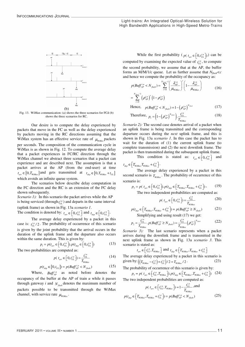
(b) Fig. 13. WiMax communication: (a) shows the three scenarios for FCd (b)
shows the three scenarios for RC.
Our desire is to compute the delay experienced by packets that move in the FC as well as the delay experienced by packets moving in the RC directions assuming that the WiMax system has an effective service rate of
WiMaxμ packets
per seconds. The composition of the communication cycle in WiMax is as shown in Fig. 12. To compute the average delay that a packet experiences in FC/RC direction through the WiMax channel we abstract three scenarios that a packet can experience and are described next. The assumption is that a packet arrives at the AP (from the end-user) at time
[ ]0,arr WiMaxt T∈ and gets transmitted at [ ]0,dep WiMax ULt T t∈ +
which avoids an infinite queue system. The scenarios below describe delay computation in
the FC direction and the RC is an extension of the FC delay shown subsequently. Scenario 1): In this scenario the packet arrives while the AP is being serviced (through ,i u
ULt ) and departs in the same interval
(uplink frame) as shown in Fig. 13a scenario 1.The condition is denoted by: ,0, i u
arr ULt t⎡ ⎤∈ ⎣ ⎦ and ,0, i u
dep ULt t⎡ ⎤∈ ⎣ ⎦.
The average delay experienced by a packet in this case is: , / 2i u
ULt . The probability of occurrence of this scenario
is given by the joint probability that the arrival occurs in the duration of the uplink frame and the departure also occurs within the same duration. This is given by:
, ,1 ( 0, ). ( 0, )i u i u
arr UL dep ULp p t t p t t⎡ ⎤ ⎡ ⎤= ∈ ∈⎣ ⎦ ⎣ ⎦ (13)
The two probabilities are computed as: ,
,( 0, )i u
i u ULarr UL
WiMax
tp t t
T⎡ ⎤∈ =⎣ ⎦
(14)
[ ] ,( 0, ) ( )i udep UL AP flushp t t p Buff N∈ = < (15)
Where, ,i uAPBuff as noted before denotes the
occupancy of the buffer at the AP of train u while it passes through gateway i and
flushN denotes the maximum number of
packets possible to be transmitted through the WiMax channel, with service rate
WiMaxμ .
While the first probability ( ,( 0, )i uarr ULp t t⎡ ⎤∈ ⎣ ⎦
) can be
computed by examining the expected value of ,i uULt , to compute
the second probability, we assume that at the AP, the buffer forms an M/M/1/c queue. Let us further assume that Nflush<cand hence we compute the probability of the occupancy as:
( ) ( )
1 , ,,
0
1, ,
0
( ) 1
1
flush
flush
rN i u i ui u AP APAP flush
r WiMax WiMax
Nri u i u
AP APr
p Buff Nλ λ
μ μ
ρ ρ
−
=
−
=
⎛ ⎞ ⎛ ⎞< = −⎜ ⎟ ⎜ ⎟
⎝ ⎠ ⎝ ⎠
= −
∑
∑
(16)
Hence, ( ), ,( ) 1flushNi u i u
AP flush APp Buff N ρ< = − (17)
Therefore, ( )( ),
,1 1 .
flushi u
Ni u ULAP
WiMax
tp
Tρ= − (18)
Scenario 2): The second case denotes arrival of a packet when an uplink frame is being transmitted and the corresponding departure occurs during the next uplink frame, and this is shown in Fig. 13a scenario 1. In this case the packet has to wait for the duration of (1) the current uplink frame (to complete transmission) and (2) the next downlink frame. The packet is then transmitted during the subsequent uplink frame.
This condition is stated as: ,0, i uarr ULt t⎡ ⎤∈ ⎣ ⎦
and
,,
i udep WiMax WiMax ULt T T t⎡ ⎤∈ +⎣ ⎦
.
The average delay experienced by a packet in this second scenario is
WiMaxT . The probability of occurrence of this
scenario is: , ,
2 ( 0, ). ( , )i u i uarr UL dep WiMax WiMax ULp p t t p t T T t⎡ ⎤ ⎡ ⎤= ∈ ∈ +⎣ ⎦ ⎣ ⎦
, (19)
The two independent probabilities are computed as: ,
,( 0, )i u
i u ULarr UL
WiMax
tp t t
T⎡ ⎤∈ =⎣ ⎦
(20)
, ,( , ) ( )i u i udep WiMax WiMax UL AP flushp t T T t p Buff N⎡ ⎤∈ + = ≥⎣ ⎦
(21)
Simplifying and using result (17) we get:
( ), ,
, ,2 . ( )
flushi u i u
Ni u i uUL ULAP flush AP
WiMax WiMax
t tp p Buff N
T Tρ= ≥ = (22)
Scenario 3): The last scenario represents when a packet arrives during the downlink frame and is transmitted in the next uplink frame as shown in Fig. 13a scenario 3. This scenario is stated as:
, ,i uarr UL WiMaxt t T⎡ ⎤∈ ⎣ ⎦
and ,, i udep WiMax WiMax ULt T T t⎡ ⎤∈ +⎣ ⎦
The average delay experienced by a packet in this scenario is given by: ( )( ), , / 2 / 2i u i u
WiMax UL UL WiMaxT t t T− + = . (23)
The probability of occurrence of this scenario is given by: , ,
3 ( , ). ( , )i u i uarr UL WiMax dep WiMax WiMax ULp p t t T p t T T t⎡ ⎤ ⎡ ⎤= ∈ ∈ +⎣ ⎦ ⎣ ⎦
(24)
The two independent probabilities are computed as: ,
,( , ) 1i u
i u ULarr UL WiMax
WiMax
tp t t T
T⎡ ⎤∈ = −⎣ ⎦
,and
, ,( , ) ( )i u i udep WiMax WiMax UL AP flushp t T T t p Buff N⎡ ⎤∈ + = <⎣ ⎦
(25)
Light-trains: An Integrated Optical-Wireless Solution forHigh Bandwidth Applications in High-Speed Metro-Trains
INFOCOMMUNICATIONS JOURNAL
12 FEBRUARY 2011 • VOLUME III • NUMBER 1
Hence, ( ),
,3 1 . 1
N flushi ui uULAP
WiMax
tp
Tρ
⎛ ⎞ ⎛ ⎞= − −⎜ ⎟ ⎜ ⎟
⎝ ⎠⎝ ⎠
(26)
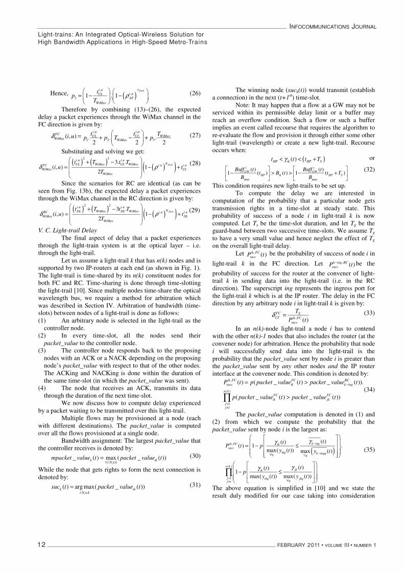
Therefore by combining (13)–(26), the expected delay a packet experiences through the WiMax channel in the FC direction is given by:
( , )FCWiMax i uδ =
, ,
1 2 3. . .2 2 2
i u i uUL UL WiMax
WiMax
t t Tp p T p
⎛ ⎞+ − +⎜ ⎟
⎝ ⎠
(27)
Substituting and solving we get:
( ) ( )( )( )
2 2. .
, .3. .
( , ) 12
flush
i u i uNUL WiMax UL WiMaxFC i u i u
WiMax ULWiMax
t T t Ti u t
Tδ ρ
⎛ ⎞+ −⎜ ⎟= − +⎜ ⎟⎝ ⎠
(28)
Since the scenarios for RC are identical (as can be seen from Fig. 13b), the expected delay a packet experiences through the WiMax channel in the RC direction is given by:
( ) ( )( )( )
2 2. .
, .3 .
( , ) 12
flush
i u i uNDL WiMax DL WiMaxRC i u i u
WiMax DLWiMax
t T t Ti u t
Tδ ρ
⎛ ⎞+ −⎜ ⎟= − +⎜ ⎟⎝ ⎠
(29)
V. C. Light-trail Delay The final aspect of delay that a packet experiences
through the light-train system is at the optical layer – i.e. through the light-trail.
Let us assume a light-trail k that has n(k) nodes and is supported by two IP-routers at each end (as shown in Fig. 1). The light-trail is time-shared by its n(k) constituent nodes for both FC and RC. Time-sharing is done through time-slotting the light-trail [10]. Since multiple nodes time-share the optical wavelength bus, we require a method for arbitration which was described in Section IV. Arbitration of bandwidth (time-slots) between nodes of a light-trail is done as follows: (1) An arbitrary node is selected in the light-trail as the
controller node. (2) In every time-slot, all the nodes send their
packet_value to the controller node. (3) The controller node responds back to the proposing
nodes with an ACK or a NACK depending on the proposing node’s packet_value with respect to that of the other nodes. The ACKing and NACKing is done within the duration of the same time-slot (in which the packet_value was sent).
(4) The node that receives an ACK, transmits its data through the duration of the next time-slot.
We now discuss how to compute delay experienced by a packet waiting to be transmitted over this light-trail.
Multiple flows may be provisioned at a node (each with different destinations). The packet_value is computed over all the flows provisioned at a single node.
Bandwidth assignment: The largest packet_value that the controller receives is denoted by:
:_ ( ) max ( _ ( ))
ik ik
i N kmpacket value t packet value t
∀ ∈= (30)
While the node that gets rights to form the next connection is denoted by:
:( ) arg max( _ ( ))
i
k iki N k
suc t packet value t∈
= (31)
The winning node (suck(t)) would transmit (establish a connection) in the next (t+1st) time-slot.
Note: It may happen that a flow at a GW may not be serviced within its permissible delay limit or a buffer may reach an overflow condition. Such a flow or such a buffer implies an event called recourse that requires the algorithm to re-evaluate the flow and provision it through either some other light-trail (wavelength) or create a new light-trail. Recourse occurs when:
( )( )HP ik HP St t t Tγ< < + or
max max
( ) ( )1 ( ) ( ) 1 ( )
i iGW GW
HP ik HP S
Buff t Buff tt B t t T
B B
⎡ ⎤ ⎡ ⎤− > > − +⎢ ⎥ ⎢ ⎥
⎣ ⎦ ⎣ ⎦
(32)
This condition requires new light-trails to be set up. To compute the delay we are interested in
computation of the probability that a particular node gets transmission rights in a time-slot at steady state. This probability of success of a node i in light-trail k is now computed. Let Ts be the time-slot duration, and let Tg be the guard-band between two successive time-slots. We assume Tg
to have a very small value and hence neglect the effect of Tg
on the overall light-trail delay. Let , ( )ik FC
succP t be the probability of success of node i in
light-trail k in the FC direction. Let , ( )k ing RCsuccP t− be the
probability of success for the router at the convener of light-trail k in sending data into the light-trail (i.e. in the RC direction). The superscript ing represents the ingress port for the light-trail k which is at the IP router. The delay in the FC direction by any arbitrary node i in light-trail k is given by:
, ( )FC SLT ik FC
succ
T
P tδ = (33)
In an n(k)-node light-trail a node i has to contend with the other n(k)-1 nodes that also includes the router (at the convener node) for arbitration. Hence the probability that node i will successfully send data into the light-trail is the probability that the packet_value sent by node i is greater than the packet_value sent by any other nodes and the IP router interface at the convener node. This condition is denoted by:
,
( )
1
( ) ( _ ( ) _ ( )).
( _ ( ) _ ( ))
ik FC FC RCsucc ik k ing
n kFC FCik jk
jj i
P t p packet value t packet value t
p packet value t packet value t
−
=≠
= >
>∏(34)
The packet_value computation is denoted in (1) and (2) from which we compute the probability that the packet_value sent by node i is the largest as:
( ),
( )
1
( )( )( ) 1 .
max( ( )) max ( )
( )( )1
max( ( )) max( ( ))
k ingik FC iksucc
ikq k ingqq q
n kjkik
j ikq jkqqj i
ttP t p
y t y t
ttp
y t y t
γγ
γγ
−
−∀ ∀
=∀≠
⎛ ⎞⎡ ⎤⎜ ⎟⎢ ⎥= − ≤⎜ ⎟⎢ ⎥⎜ ⎟⎢ ⎥⎣ ⎦⎝ ⎠
⎛ ⎞⎡ ⎤⎜ ⎟⎢ ⎥− ≤⎜ ⎟⎢ ⎥⎜ ⎟
⎣ ⎦⎝ ⎠
∏
(35)
The above equation is simplified in [10] and we state the result duly modified for our case taking into consideration
Light-trains: An Integrated Optical-Wireless Solution forHigh Bandwidth Applications in High-Speed Metro-Trains

INFOCOMMUNICATIONS JOURNAL
FEBRUARY 2011 • VOLUME III • NUMBER 1 13
duplex communication over the simplex light-trails (time shared FC and RC) as:
( )1 1,
0 01
( ) 1 ( ) . 1 ( )n k
ik FCsucc
jj i
P tφ φ
δ φ δ φ= ==
≠
⎛ ⎞ ⎛ ⎞= − −⎜ ⎟ ⎜ ⎟⎝ ⎠ ⎝ ⎠∑ ∑∏
(36)
where, ( )( ) / max ( )
( ) / max( ( ))
k ing k ingqq
ik ikqq
t y t
t y t
γφ
γ
− −∀
∀
= and( ) / max( ( ))
( ) / max( ( ))
jk jkqq
ik ikqq
t y t
t y t
γφ
γ∀
∀
=
1 1( ) ( )1 1,
0 01 10 0
( ) 1 ( ) . 1 ( ) 1 ( ') ' . 1 ( )n k n k
ik FCsucc
j jj i j i
P t d dφ φ
δ φ δ φ δ φ φ δ φ φ= == =
≠ ≠
⎛ ⎞ ⎛ ⎞⎛ ⎞ ⎛ ⎞= − − = − −⎜ ⎟ ⎜ ⎟⎜ ⎟ ⎜ ⎟⎝ ⎠ ⎝ ⎠ ⎝ ⎠ ⎝ ⎠∑ ∑∏ ∏∫ ∫
(37) and
( )max ( )
( )( )( ) ( ). ( )
max( ( )) max( ( ))
qiq Buff tGW
HP
jkik
v t ikq jkqq q
ttQ p vQ p v v
y t y t
γγδ
∈
Δ
=∀ ∀
= = =∑
(38) Leading to:
, ( )FC SLT k ing FC
succ
T
P tδ
−= (39)
The average delay experienced by a packet in the RC direction is computed in a similar fashion:
( ),
1
( ) ( _ ( ) _ ( ))n k
k ing RC RC FCsucc k ing jk
j
P t p packet value t packet value t−−
=
= >∏ (40)
( )
( ),
1
( ) ( )( ) 1
max( ( ))max ( )
n kk ing jkk ing RC
succj jkqk ingq qq
t tP t p
y ty t
γ γ−−
= − ∀∀
⎛ ⎞⎡ ⎤⎜ ⎟⎢ ⎥= − ≤⎜ ⎟⎢ ⎥⎜ ⎟⎢ ⎥⎣ ⎦⎝ ⎠
∏ (41)
1( ) ( )1,
01 1 0
( ) 1 ( ') 1 ( ') 'n k n k
k ing RCsucc
j j
P t dφ
δ φ δ φ φ−
== =
⎛ ⎞⎛ ⎞= − = −⎜ ⎟⎜ ⎟
⎝ ⎠ ⎝ ⎠∑∏ ∏ ∫ (42)
Where, ( ) / max( ( ))
'( ) / max ( ( ))
jk jkqq
k ing k ingqq
t y t
t y t
γφ
γ
∀
− −∀
=
The delay in the RC direction is given by:
, ( )RC SLT k ing RC
succ
T
P tδ
−= (43)
The delays computed in (28), (29) for WiMax, (33), (43) for light-trail are plugged in (3)-(5) to obtain final end-to-end delay, neglecting propagation delay.
VI. RELATED WORK
The concept of providing broadband connectivity to moving users especially fast moving users has been studied in [8], [12], [13], of which the [12] is our own preliminary work.
The approach in [12] proposed the basic architecture – using the light-trail node to serve as an element to provide dynamic provisioning and optical multicasting. This work however did not outline the technology used at the wireless layer nor did it analyze the system for delay and utilization. No protocol was presented for delivery of bandwidth to the end-user through the unified optical-wireless network.
The work in [8, 13] mentions two approaches – the mobile cell concept in [13] and the moving tunnel concept in [8]. While this fundamental work provides a prelude to the problem as well as outlines two solutions, our work differs from the aforementioned two approaches in terms of defining a technology solution. We present a complete end-to-end optical + wireless solution that spans across the network, data and physical layers using contemporary or available technology. In [8, 13] a radio-over-fiber solution is presented – which does not delve into the specifics in terms of architecture, protocol or working. In contrast, our solution defines the node architecture, protocol as well as how to provision bandwidth from user to the network. The solution in [8, 13] uses switching which is detrimental (due to switching speed/uncertainty) in providing bandwidth to fast moving users. The requirement of optical switching in [8, 13] means either that hand-off would suffer (due to infancy of optical technology) or that we require futuristic high-speed optical switches. The light-train scheme relies on existing available, mature technologies, and is glued together by an out-of-band protocol designed to provision (without optical switching) as well as facilitate hand-off at the wireless layer. Our method of integration of optical and wireless technologies, enabling a symbiotic relationship is the key differentiator between the light-train solution and other existing solutions. VI.A. Qualitative argument for Light-trails as opposed to conventional solutions:
In this subsection we outline the differences and advantages of light-trails as opposed to conventional point-to point circuit technology. (1) The 2-layer (data + control) light-trail enables dynamic sub-wavelength provisioning of bandwidth by fostering a unique node architecture that supports an optical bus, while using the standard ITU defined OOB control channel to dynamically arbitrate bandwidth within the bus. The dual layered approach allows fast configuration (provisioning) of bandwidth, while also supporting optical multicasting. (2) Dynamic provisioning is an essential requirement for fast-hand offs – typically those envisioned for such applications like fast moving trains. The fast hand-off concept stems from two critical requirements: (a) reduction of time allocated for hand-off to maintain seamless and efficient communication under a large ratio of train size to cell-width, and (b) due to the high velocity of the train itself – requiring dynamic provisioning of bandwidth to efficiently utilize the wireless channel (if the time required for hand-off is large, then time lost in provisioning the connection when a train moves from one cell to its adjacent neighbor is also large and hence the efficiency of the system degrades). A fast hand-off concept is investigated by us in [14]. (3) The light-trail provides optical multicasting support. In conjunction with the dynamic provisioning property, this feature acts as a further enabler for seamless communication in the overlaid wireless channel. With optical multicasting support, when a train moves from the range of an ingress cell site to the adjacent egress cell site (GW), the data is readily
Light-trains: An Integrated Optical-Wireless Solution forHigh Bandwidth Applications in High-Speed Metro-Trains
INFOCOMMUNICATIONS JOURNAL
14 FEBRUARY 2011 • VOLUME III • NUMBER 1
available at the egress GW. This means that there is no requirement for further signaling to set up a new connection between the network core router and the new GW, and this eliminates the need for pre-fetching. In the conventional case, i.e. using an Ethernet network like the one proposed in [8, 13] or using a backbone SONET/SDH network, we would require layer 3 termination [13] and further provisioning of a moving tunnel type concept. The time required would result in loss of bandwidth and hence degradation of system efficiency.
Our model based on three factors, namely, (a) absence of pre-fetching due to optical multicasting (b) dynamic provisioning of bandwidth within the light-trail bus and (c) the presence of an OOB control that allows an egress GW to accurately estimate the starting and ending times of the train within its range (and hence schedule data accordingly), are key to a low-latency high-efficiency and evolutionary approach to integrated optical-wireless design for support of fast moving and bandwidth intensive users.
VII. SIMULATION AND RESULTS
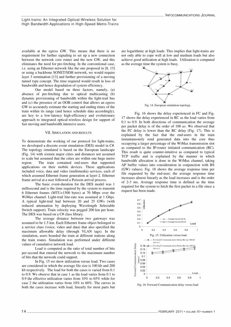
To demonstrate the working of our protocol for light-trains, we developed a discrete event simulation (DES) model in C#. The topology simulated is based on the European landscape (Fig. 14) with sixteen major cities and distances not assumed to scale but assumed that the cities are within one huge metro region. The train contained end-users that supported applications on their mobile devices. These applications included voice, data and video (multimedia) services, each of which assumed Ethernet frame generation at layer-2. Ethernet frame arrival at a user followed a Poisson arrival process.
The basic event-duration for the DES model was 1 millisecond and is the time required by the system to transmit 6 Ethernet frames (MTU=1500 bytes) at 70 Mbps over the WiMax channel. Light-trail line-rate was assumed at 1 Gbps. A typical light-trail had between 20 and 25 GWs (with reduced attenuation by deploying Wavelength Selectable Switch support). Train velocity was pegged 200 km per hour. The DES was based on a C# class library.
The average distance between two gateways was assumed to be 1.5 km. Each Ethernet frame object belonged to a service class (voice, video and data) that also specified the maximum allowable delay (through VLAN tags). In the simulation, users boarded the train at different stations along the train routes. Simulation was performed under different values of cumulative network load.
Load is computed as the ratio of total number of bits per-second that entered the network to the maximum number of bits that the network could support.
In Fig. 15 we show utilization versus load. Two cases are considered in which the average file size is 100 kb and 200 kb respectively. The load for both the cases is varied from 0.1 to 0.9. We observe that in case 1 as the load varies from 0.1 to 0.9 the effective utilization varies from 10% to 65% while for case 2 the utilization varies from 10% to 60%. The curves in both the cases increase with load, linearly for most parts but
are logarithmic at high loads. This implies that light-trains are not only able to cope well at low and medium loads but also achieve good utilization at high loads. Utilization is computed as the average time the system is busy.
Fig. 14. European simulation topology.
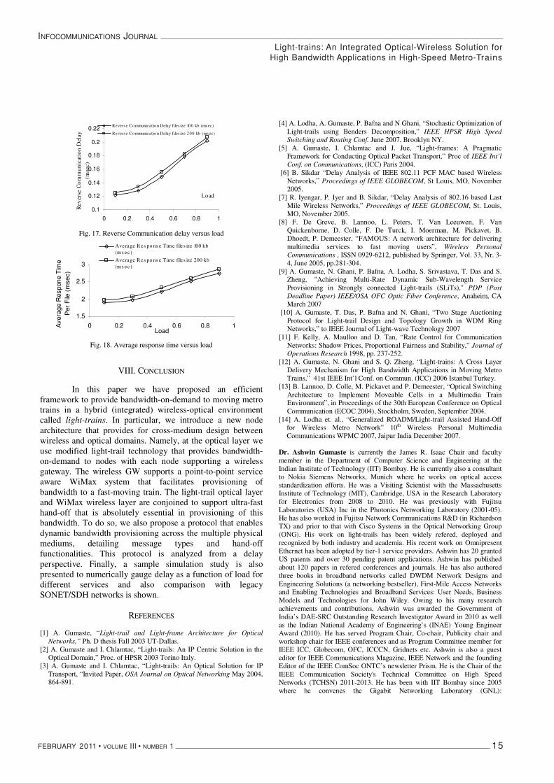
Fig. 16 shows the delay experienced in FC and Fig. 17 shows the delay experienced in RC as the load varies from 0.1 to 0.9. In both directions of communication the average per packet delay is of the order of 100 us. We observed that the FC delay is lower than the RC delay (Fig. 17). This is explained by the fact that the end-users in the train instantaneously send generated data into the core thus occupying a larger percentage of the WiMax transmission slot as compared to the IP-router initiated communication (RC). This result is quite counter-intuitive as compared to typical TCP traffic and is explained by the manner in which bandwidth allocation is done in the WiMax channel, taking AP buffer values into consideration in conjunction with BS (GW) values). Fig. 18 shows the average response time per file requested by the end-user; the average response time increases almost linearly as the load increases and is the order of 2-3 ms. Average response time is defined as the time required for the system to fetch the first packet in a file since a request has been made.
�
0
0.1
0.2
0.3
0.4
0.5
0.6
0.7
0 0.2 0.4 0.6 0.8 1
Load
Util
izat
ion
Average f ile size 100 kb
Average f ile size 200 kb
Fig. 15. Utilization versus load �
00.02
0.040.060.08
0.10.120.140.16
0 0.2 0.4 0.6 0.8 1
Load
Forw
ard
Com
mun
icat
ion
Del
ay
(mse
c)
Fo rward Co mmunicatio n De lay file s ize 100 kb(ms ec)
Fo rward Co mmunicatio n De lay file s ize 200 kb(ms ec)
Fig. 16: Forward Communication delay versus load
Light-trains: An Integrated Optical-Wireless Solution forHigh Bandwidth Applications in High-Speed Metro-Trains
INFOCOMMUNICATIONS JOURNAL
FEBRUARY 2011 • VOLUME III • NUMBER 1 15
�
0.1
0.12
0.14
0.16
0.18
0.2
0.22
0 0.2 0.4 0.6 0.8 1
Load
Rev
erse
Com
mun
icat
ion
Del
ay
(mse
c)
Reverse Co mmunicat io n Delay files ize 10 0 kb (msec)
Reverse Co mmunicat io n Delay files ize 2 00 kb (msec)
Fig. 17. Reverse Communication delay versus load
�
1.5
2
2.5
3
0 0.2 0.4 0.6 0.8 1Load
Ave
rage
Res
pone
Tim
e P
er F
ile(m
sec)
Average R es po ns e Time file s ize 100 kb(ms ec )
Average R es po ns e Time file s ize 200 kb(ms ec )
Fig. 18. Average response time versus load
VIII. CONCLUSION
In this paper we have proposed an efficient framework to provide bandwidth-on-demand to moving metro trains in a hybrid (integrated) wireless-optical environment called light-trains. In particular, we introduce a new node architecture that provides for cross-medium design between wireless and optical domains. Namely, at the optical layer we use modified light-trail technology that provides bandwidth-on-demand to nodes with each node supporting a wireless gateway. The wireless GW supports a point-to-point service aware WiMax system that facilitates provisioning of bandwidth to a fast-moving train. The light-trail optical layer and WiMax wireless layer are conjoined to support ultra-fast hand-off that is absolutely essential in provisioning of this bandwidth. To do so, we also propose a protocol that enables dynamic bandwidth provisioning across the multiple physical mediums, detailing message types and hand-off functionalities. This protocol is analyzed from a delay perspective. Finally, a sample simulation study is also presented to numerically gauge delay as a function of load for different services and also comparison with legacy SONET/SDH networks is shown.
REFERENCES
[1] A. Gumaste, “Light-trail and Light-frame Architecture for Optical Networks,” Ph. D thesis Fall 2003 UT-Dallas.
[2] A. Gumaste and I. Chlamtac, “Light-trails: An IP Centric Solution in the Optical Domain,” Proc. of HPSR 2003 Torino Italy.
[3] A. Gumaste and I. Chlamtac, “Light-trails: An Optical Solution for IP Transport, “Invited Paper, OSA Journal on Optical Networking May 2004, 864-891.
[4] A. Lodha, A. Gumaste, P. Bafna and N Ghani, “Stochastic Optimization of Light-trails using Benders Decomposition,” IEEE HPSR High Speed Switching and Routing Conf. June 2007, Brooklyn NY.
[5] A. Gumaste, I. Chlamtac and J. Jue, “Light-frames: A Pragmatic Framework for Conducting Optical Packet Transport,” Proc of IEEE Int’l Conf. on Communications, (ICC) Paris 2004.
[6] B. Sikdar “Delay Analysis of IEEE 802.11 PCF MAC based Wireless Networks,” Proceedings of IEEE GLOBECOM, St Louis, MO, November 2005.
[7] R. Iyengar, P. Iyer and B. Sikdar, “Delay Analysis of 802.16 based Last Mile Wireless Networks,” Proceedings of IEEE GLOBECOM, St. Louis, MO, November 2005.
[8] F. De Greve, B. Lannoo, L. Peters, T. Van Leeuwen, F. Van Quickenborne, D. Colle, F. De Turck, I. Moerman, M. Pickavet, B. Dhoedt, P. Demeester, “FAMOUS: A network architecture for delivering multimedia services to fast moving users”, Wireless Personal Communications , ISSN 0929-6212, published by Springer, Vol. 33, Nr. 3-4, June 2005, pp.281-304.
[9] A. Gumaste, N. Ghani, P. Bafna, A. Lodha, S. Srivastava, T. Das and S. Zheng, "Achieving Multi-Rate Dynamic Sub-Wavelength Service Provisioning in Strongly connected Light-trails (SLiTs)," PDP (Post Deadline Paper) IEEE/OSA OFC Optic Fiber Conference, Anaheim, CA March 2007
[10] A. Gumaste, T. Das, P. Bafna and N. Ghani, “Two Stage Auctioning Protocol for Light-trail Design and Topology Growth in WDM Ring Networks,” to IEEE Journal of Light-wave Technology 2007
[11] F. Kelly, A. Maulloo and D. Tan, “Rate Control for Communication Networks: Shadow Prices, Proportional Fairness and Stability,” Journal of Operations Research 1998, pp. 237-252.
[12] A. Gumaste, N. Ghani and S. Q. Zheng, “Light-trains: A Cross Layer Delivery Mechanism for High Bandwidth Applications in Moving Metro Trains,” 41st IEEE Int’l Conf. on Commun. (ICC) 2006 Istanbul Turkey.
[13] B. Lannoo, D. Colle, M. Pickavet and P. Demeester, “Optical Switching Architecture to Implement Moveable Cells in a Multimedia Train Environment”, in Proceedings of the 30th European Conference on Optical Communication (ECOC 2004), Stockholm, Sweden, September 2004.
[14] A. Lodha et. al., “Generalized ROADM/Light-trail Assisted Hand-Off for Wireless Metro Network” 10th Wireless Personal Multimedia Communications WPMC 2007, Jaipur India December 2007.
Dr. Ashwin Gumaste is currently the James R. Isaac Chair and faculty member in the Department of Computer Science and Engineering at the Indian Institute of Technology (IIT) Bombay. He is currently also a consultant to Nokia Siemens Networks, Munich where he works on optical access standardization efforts. He was a Visiting Scientist with the Massachusetts Institute of Technology (MIT), Cambridge, USA in the Research Laboratory for Electronics from 2008 to 2010. He was previously with Fujitsu Laboratories (USA) Inc in the Photonics Networking Laboratory (2001-05). He has also worked in Fujitsu Network Communications R&D (in Richardson TX) and prior to that with Cisco Systems in the Optical Networking Group (ONG). His work on light-trails has been widely refered, deployed and recognized by both industry and academia. His recent work on Omnipresent Ethernet has been adopted by tier-1 service providers. Ashwin has 20 granted US patents and over 30 pending patent applications. Ashwin has published about 120 papers in refered conferences and journals. He has also authored three books in broadband networks called DWDM Network Designs and Engineering Solutions (a networking bestseller), First-Mile Access Networks and Enabling Technologies and Broadband Services: User Needs, Business Models and Technologies for John Wiley. Owing to his many research achievements and contributions, Ashwin was awarded the Government of India’s DAE-SRC Outstanding Research Investigator Award in 2010 as well as the Indian National Academy of Engineering’s (INAE) Young Engineer Award (2010). He has served Program Chair, Co-chair, Publicity chair and workshop chair for IEEE conferences and as Program Committee member for IEEE ICC, Globecom, OFC, ICCCN, Gridnets etc. Ashwin is also a guest editor for IEEE Communications Magazine, IEEE Network and the founding Editor of the IEEE ComSoc ONTC’s newsletter Prism. He is the Chair of the IEEE Communication Society's Technical Committee on High Speed Networks (TCHSN) 2011-2013. He has been with IIT Bombay since 2005 where he convenes the Gigabit Networking Laboratory (GNL):
Light-trains: An Integrated Optical-Wireless Solution forHigh Bandwidth Applications in High-Speed Metro-Trains

INFOCOMMUNICATIONS JOURNAL
16 FEBRUARY 2011 • VOLUME III • NUMBER 1
www.cse.iitb.ac.in/gnl. The Gigabit Networking Laboratory has secured over 8 million USD in funding since its inception and has been involved in 4 major technology transfers to the industry. Ashwin can be reached through www.ashwin.name.
Akhil Lodha is currently working as Quantative Analyst on the Electronic Options Trading desk at Citigroup, New York. He completed MS in Computational Finance from Carnegie Mellon University and Dual degree from IIT, Bombay.
Saurabh Mehta is currently pursuing his PhD from Gigabit Networking Laboratory in the Department of Computer Science and Engineering, IIT Bombay. Earlier, he worked with Center for Development of Advanced Computing (C-DAC), Pune for the development of PARAM series of Supercomputers. His research interests include access and metro networks, high-performance computing and real-time systems.
Dr. Jianping Wang is currently an assistant professor in the Department of Computer Science at City University of Hong Kong. She received her BSc and MSc degrees from Nankai University in 1996 and 1999 respectively, and her Ph.D. degree from University of Texas at Dallas in 2003. Prior to joining CityU, she worked at Georgia Southern University and University of Mississippi as an assistant professor.
Dr. Nasir Ghani is an Associate Professor in the Electrical and Computer Engineering Department at the University of New Mexico and Director of the UNM Advanced Cyberinfrastructure Lab. He received the Bachelors degree in Computer Engineering from the University of Waterloo, Canada, the Masters degree in Electrical Engineering from McMaster University, Canada, and the Ph.D. degree in Computer Engineering from the University of Waterloo, Canada.
Light-trains: An Integrated Optical-Wireless Solution forHigh Bandwidth Applications in High-Speed Metro-Trains
NaviSensor technology as a breakthrough in the navigation of the blind
70% of our information comes through vision. As blindpeople put this in a very simple way; „we live in the world ofseers”. Thinking of what it would be like to lose our sight thefirst things that come to our mind are the lack of pictures,films, sights and reading. However, in reality the biggest prob-lem for blind people is the narrowing possibility of naviga-tion. It is not an exaggeration to state that – in a certain sense– navigation is harder for the blind than it is for the disabled.
Zojox-2000 Ltd. had set an ambitious goal to themselveswhen, funded by the Hungarian research and developmentprogram KMOP 2009-1.1.1, started with the realisation of anappliance that would make both static and moving objectssensible for blind people and help them determine their ownposition in their navigation space, thus enabling them to reachtheir destination more safely.
Short description of the systemNaviSensor maps its surroundings in 360° by a continu-
ous circular 40 kHz ultrasound sweep. It determines the dis-tance of obstacles by the running time (time elapsed from theemission to the return) of the ultrasound sign reflected bylandmark objects.
The transmission and reception of the ultrasound is madepossible by one single piece of universal 60° conic ultra-sound capsule. Circular mapping is done by a parabolic mir-ror, which is specially designed for this purpose and whichrotates the cluster that exits the capsule, just like in a light-house. By using a mirror for the 360° sweep one single ultra-sound device is enough, while the parabola also performsthe concentration of the emitted cluster, which results in astronger transmission and reception sign, thus enhancingthe range of the appliance.
Information of space (distance and place) are mapped byultrasound and encoded to sound information which is trans-mitted to the user through a 5.1 headphone. The sound sys-tem ensures spatial mapping, as each sound comes fromthe direction of an obstacle. A more exact perception of thedirection is made possible by different sound motifs repre-senting different directions. Distance is represented by vol-ume; the nearer an object, the louder the sound motif is. Whenan obstacle is getting dangerously near, the user is warnedby an accelerating intermission of the sound motif.
Areas of research done for the development of NaviSensor technology• Present general knowledge about ultrasound navigation,
especially considering animals in nature using ultrasoundnavigation (e.g. bats, dolphins)
• Practical problems of the presently best attainable ultrasound distance measuring technique
• Getting familiar with appliances developed especially for the blind, applying of technologies in order to compareresults
• Research on the navigation and traffic issues of blind people • Anatomical and physiological background of processing
auditory informationResearch results and the present state of development
give reassuring proof that the developed technology is notonly operable, but also results in an appliance which can beused in practice. Info: www.navisensor.hu
(x)AD
VE
RT
ISE
ME
NT