light gauge metal roof and wall panels...light gauge metal roof and wall panels installation guide...
TRANSCRIPT
Light Gauge Metal Roof and Wall Panels
Installation Guide for Delta Rib, Delta Rib III,Nor-Clad®, Strata Rib® & 21⁄2 Corrugated
light gauge Metal Roof and Wall Panels Installation • April 2013 1
ASC Building ProductsA Division of ASC Profiles LLC
Table of Contents
SectionIntroduction . . . . . . . . . . . . . . . . . . . . . . . . . . . . . . . . . . . . . .2
Minimum Recommended tools & equipment . . . . . . . . 2-3
delivery, Handling & Storage . . . . . . . . . . . . . . . . 3
Safety Considerations . . . . . . . . . . . . . . . . . . . . . . . . . . . . .3
Roof Preparation . . . . . . . . . . . . . . . . . . . . . . . . . . . . . . . . . .4
Map of typical Roof Conditions . . . . . . . . . . . . . . . . . . . . . .5
trim locations . . . . . . . . . . . . . . . . . . . . . . . . . . . . . . . . . . . .6
fastener Placement . . . . . . . . . . . . . . . . . . . . . . . . . . . . . . .6
fastener Selection . . . . . . . . . . . . . . . . . . . . . . . . . . . . . . . .7
Panel Installation . . . . . . . . . . . . . . . . . . . . . . . . . . . . . . . . . .8
Hip/Ridge flashing . . . . . . . . . . . . . . . . . . . . . . . . . . . . . . . .9
Universal Ridge termination . . . . . . . . . . . . . . . . . . . . . . .10
Vented Ridge flashing . . . . . . . . . . . . . . . . . . . . . . . . . . . .11
Vented Ridge termination . . . . . . . . . . . . . . . . . . . . . . . . .12
Valley flashing . . . . . . . . . . . . . . . . . . . . . . . . . . . . . . . . . .13
Valley termination . . . . . . . . . . . . . . . . . . . . . . . . . . . . . . .14
eave and Vented eave flashings . . . . . . . . . . . . . . . . . . .15
eave flashing Preparation . . . . . . . . . . . . . . . . . . . . . . . . .16
gutter and Vented gutter flashing . . . . . . . . . . . . . . . . . .17
gable flashing . . . . . . . . . . . . . . . . . . . . . . . . . . . . . . . . . .18
gable/Ridge transition . . . . . . . . . . . . . . . . . . . . . . . . . . . .19
gable Corner at eave . . . . . . . . . . . . . . . . . . . . . . . . . . . . .19
gable flashing Preparation . . . . . . . . . . . . . . . . . . . . . . . .20
gable flashing Preparation at Ridge . . . . . . . . . . . . . . . .21
Peak flashing . . . . . . . . . . . . . . . . . . . . . . . . . . . . . . . . . . .22
Sidewall flashing . . . . . . . . . . . . . . . . . . . . . . . . . . . . . . . .23
endwall flashing . . . . . . . . . . . . . . . . . . . . . . . . . . . . . . . . .24
Vented endwall flashing . . . . . . . . . . . . . . . . . . . . . . . . . .25
SectionSlope transition - High to low Slope . . . . . . . . . . . . . . . .26
Slope transition - low to High Slope . . . . . . . . . . . . . . . .27
Chalet gable flashing . . . . . . . . . . . . . . . . . . . . . . . . . . . .28
Adjustable gable flashing . . . . . . . . . . . . . . . . . . . . . . . . .29
Vent flashing . . . . . . . . . . . . . . . . . . . . . . . . . . . . . . . . . . .30
Vent/Pipe flashing Installation Procedure . . . . . . . . 31
Skylight flashing . . . . . . . . . . . . . . . . . . . . . . . . . . . . . . . . .32
Skylight flashing (Side) . . . . . . . . . . . . . . . . . . . . . . . . . . .32
Skylight flashing (Uphill Side) . . . . . . . . . . . . . . . . . . . . . .33
Skylight flashing (downhill Side) . . . . . . . . . . . . . . . . . . .34
Procedure for the Installation of
Skylight flashings . . . . . . . . . . . . . . . . . . . . . . . . . . . .35
Skylight flashing Preparation . . . . . . . . . . . . . . . . . . . 35-36
Chimney flashing . . . . . . . . . . . . . . . . . . . . . . . . . . . . . . . .37
Chimney flashing (Side) . . . . . . . . . . . . . . . . . . . . . . . . . .38
Chimney flashing (Uphill Side) . . . . . . . . . . . . . . . . . . . . .39
Chimney flashing (downhill Side) . . . . . . . . . . . . . . . . . . .40
Valley top end . . . . . . . . . . . . . . . . . . . . . . . . . . . . . . . . . .41
Valley dormer . . . . . . . . . . . . . . . . . . . . . . . . . . . . . . . . . . .42
Panel end lap . . . . . . . . . . . . . . . . . . . . . . . . . . . . . . . . . .43
Sealing end laps & lapping the Hems . . . . . . . . . . . . . .44
Window/door trim Corner Wall detail . . . . . . . . . . . . . . .45
Base trim, Wall Step, Panel top Wall detail . . . . . . . . . .46
Inside Corner Wall detail . . . . . . . . . . . . . . . . . . . . . . . . . .47
outside Corner Wall detail . . . . . . . . . . . . . . . . . . . . . . . . .48
Light Gauge Metal Roof & Wall Panels
2 April 2013 www.ascbp.com
Light Gauge Metal Roof and Wall Panels Installation Guide for Delta Rib, Delta Rib III, Nor-Clad®, Strata Rib® & 2½ Corrugated
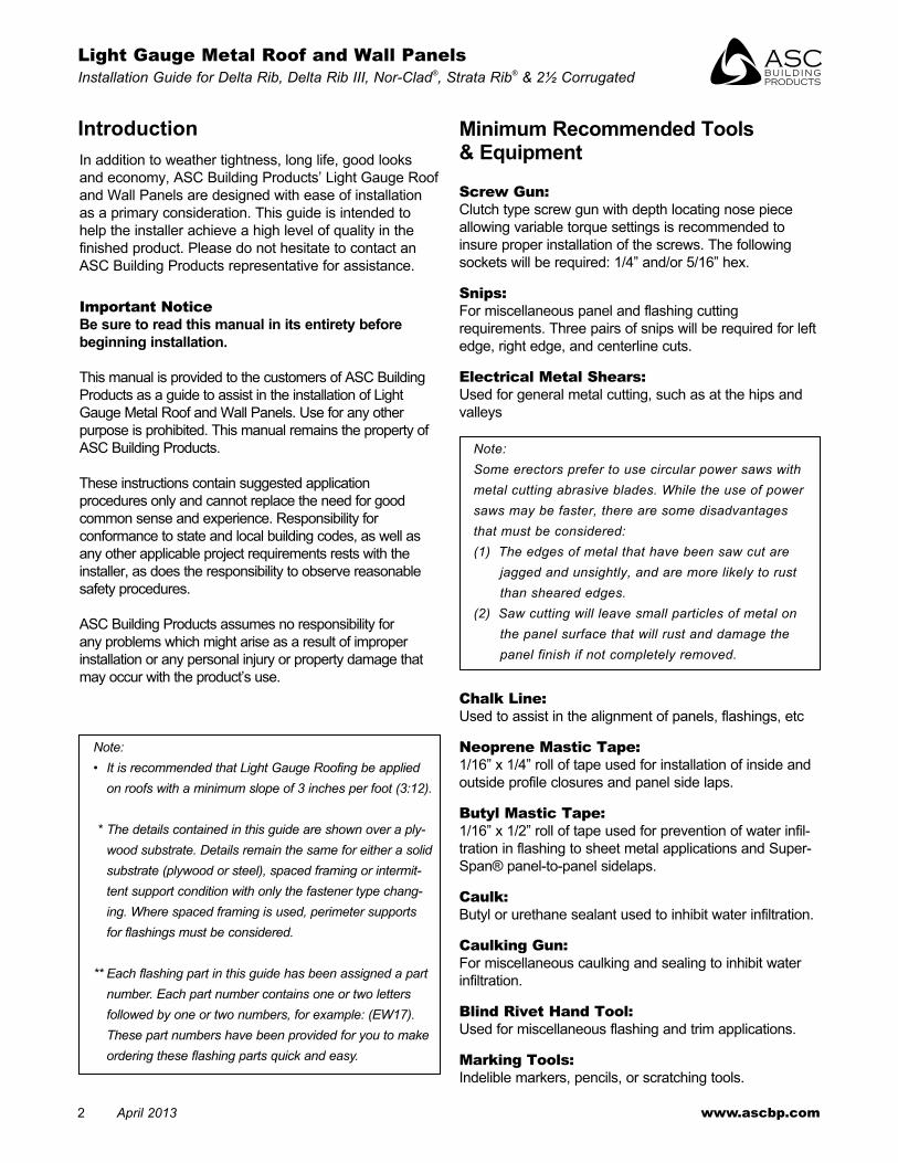
In addition to weather tightness, long life, good looks and economy, ASC Building Products’ light gauge Roof and Wall Panels are designed with ease of installation as a primary consideration . this guide is intended to help the installer achieve a high level of quality in the finished product . Please do not hesitate to contact an ASC Building Products representative for assistance .
Important NoticeBe sure to read this manual in its entirety before beginning installation.
this manual is provided to the customers of ASC Building Products as a guide to assist in the installation of light gauge Metal Roof and Wall Panels . Use for any other purpose is prohibited . this manual remains the property of ASC Building Products .
these instructions contain suggested application procedures only and cannot replace the need for good common sense and experience . Responsibility for conformance to state and local building codes, as well as any other ap pli ca ble project requirements rests with the installer, as does the responsibility to observe reasonable safety procedures .
ASC Building Products assumes no responsibility for any problems which might arise as a result of improper installation or any personal injury or property damage that may occur with the product’s use .
Introduction
Screw Gun: Clutch type screw gun with depth locating nose piece allowing variable torque settings is recommended to insure proper installation of the screws . the following sockets will be required: 1/4” and/or 5/16” hex .
Snips: for miscellaneous panel and flashing cutting requirements . three pairs of snips will be required for left edge, right edge, and centerline cuts .
Electrical Metal Shears: Used for general metal cutting, such as at the hips and valleys
Note: Some erectors prefer to use circular power saws with metal cutting abrasive blades. While the use of power saws may be faster, there are some disadvantages that must be considered: (1) The edges of metal that have been saw cut are
jagged and unsightly, and are more likely to rust than sheared edges.
(2) Saw cutting will leave small particles of metal on the panel surface that will rust and damage the panel finish if not completely removed.
Chalk Line: Used to assist in the alignment of panels, flashings, etc
Neoprene Mastic Tape: 1/16” x 1/4” roll of tape used for installation of inside and outside profile closures and panel side laps .
Butyl Mastic Tape: 1/16” x 1/2” roll of tape used for prevention of water infil-tration in flashing to sheet metal applications and Super-Span® panel-to-panel sidelaps .
Caulk: Butyl or urethane sealant used to inhibit water infiltration .
Caulking Gun: for miscellaneous caulking and sealing to inhibit water infiltration .
Blind Rivet Hand Tool: Used for miscellaneous flashing and trim applications .
Marking Tools: Indelible markers, pencils, or scratching tools .
Minimum Recommended Tools & Equipment
Note: • It is recommended that Light Gauge Roofing be applied
on roofs with a minimum slope of 3 inches per foot (3:12).
* The details contained in this guide are shown over a ply-wood substrate. Details remain the same for either a solid substrate (plywood or steel), spaced framing or intermit-tent support condition with only the fastener type chang-ing. Where spaced framing is used, perimeter supports for flashings must be considered.
** Each flashing part in this guide has been assigned a part number. Each part number contains one or two letters followed by one or two numbers, for example: (EW17). These part numbers have been provided for you to make ordering these flashing parts quick and easy.

light gauge Metal Roof and Wall Panels Installation • April 2013 3
ASC Building ProductsA Division of ASC Profiles LLC
Minimum Recommended Tools & Equipment (Con’t)Scratch Awl: Used to mark the steel .
Utility Knife: Used for miscellaneous cutting .
Electric Drill: Used to drill holes such as those required for rivet installation .
String Line: Used for general alignment and measuring .
Tape Measure: 25 foot minimum (another 50 ft . is handy) .
Locking Pliers: Standard and “duckbill” style for miscellaneous clamping and bending of parts .
Delivery, Handling and Storage
• Always check the shipment upon delivery . Check for damage and check material quantities against the shipping list . note any damaged material or shortages at the time of delivery .
• Handle panel bundles and individual panels with care to avoid damage . longer bundles and panels may require two or more “pick points” properly spaced to avoid damage that can result from buckling and/or bending of the panels . Request a copy of the long length Handling Instructions and diagrams from ASC Building Products customer service as required .
• Store the panels and other materials in a dry, well ventilated area and away from traffic . elevate one end of the bundle so that any moisture that may have accumulated during shipping can run off . Be sure that air will be able to circulate freely around the bundles to avoid the build-up of moisture . never store materials in direct contact with the ground .
• Wear clean cotton gloves when handling unpainted Zincalume®-coated panels or flashings to avoid discoloration . Rollforming die marks (which appear black), particularly at bends, will be visible .
• Wear clean, non-marking, soft soled shoes when walking on the panels to avoid shoe marks or damage to the finish . do not step on the panel seams or ribs . Step only in the flat area of the panel .
Safety Considerations
• Never use unsecured or partially installed panels as a working platform do not walk on panels until they are in place on the roof and all of the fasteners attaching the panels to the roof have been installed .
• Metal roofing panels are slippery when wet, dusty, frosty or oily do not walk on a metal roof when any of these conditions are present . Wearing soft soled shoes will help minimize slipping and help prevent damage to the painted surfaces .
• Do not walk on the panel seams or major ribs When walking on the fully installed roof panels, be sure to step only in the flat areas of the panels .
• Always be aware of your position on the roof relative to your surroundings. take note of the locations of roof openings, roof edges, equipment, co-workers, etc .
• Always wear proper clothing and safety attire. Wear proper clothing when working with sheet metal in order to minimize the potential for cuts, abrasions, and other injuries . ASC Building Products recommends safety glasses and gloves .
• Use care when operating electrical and other power equipment. observe all manufacturer’s safety recommendations .\
• Roof installation on windy or stormy days can be dangerous . Avoid working with sheet metal products on windy or stormy days .

4 April 2013 www.ascbp.com
Light Gauge Metal Roof and Wall Panels Installation Guide for Delta Rib, Delta Rib III, Nor-Clad®, Strata Rib® & 2½ Corrugated
Roof PreparationASC’s light gauge Roofing can be used in both new construction and retrofit roofing applications . We recommend the installation of light gauge Roofing over a continuous rigid substrate such as plywood, wood decking, or over in ter mit tent supports . Contact ASC for additional information .
the following steps need to be taken to prepare the roof for installation of light gauge Roofing panels:
New Roofs:
1 . Make sure there are no nails or other objects protruding from the substrates that might puncture the underlayment or the roof panels . Clean all debris from the roof .
2 . Check all details for possible roof penetrations which must be added to the deck prior to roof panel installation .
3 . Cover the entire roof deck with a minimum of 30 lb . asphalt-saturated felt paper . Some synthetic underlayments may be used in place of felt with our roofing . Installer must ensure they meet the minimum standards of 30 lb felt and that the manufacturer has approved them for use with metal roofing . for applications over spaced framing other types of moisture barriers may be required . Begin at the eave and roll the felt horizontally (parallel to the eave) . Allow each con sec u tive course to overlap the previous one 3 inches . overlap the end a minimum of 6” when starting a new roll of felt . Areas of felt paper that have been torn or cut should be replaced or repaired prior to installation of the metal roof . (See illustration #1) .
4 . Place an alignment line along the gable end where the first roof panel will be installed . This line must be parallel to the gable edge of the roof deck and square with the eave line. Check the roof for squareness by making a 3’ line across the eave . (See illustration #2) .
Completing the 3’ x 4’ x 5’ triangle should place the 4’ edge of the triangle parallel with the gable . the first roof panel will be placed parallel with this line . Slight variations or out-of-square conditions up to 3” can be covered by the gable trims shown on page 18 .
5 . It is very important to measure the entire length of the roof from gable to gable . Correct placement of the panels will allow the panel’s ribs on each side to be covered by the gable flashing shown on page 18 . this will create a symmetrical appearance on both gables . Should this be impractical, the adjustable gable detail on page 29 can be used .
3" SIDE LAP
6" END LAP
30# FELT PAPER
ILLUSTRATION #1
ILLUSTRATION #2
ALIGNMENT LINE
DIRECTION OFPANEL APPLICATION
3' x 4' x 5' TRIANGLE4'
5'
3'
Note: In areas where snow, ice, and heavy rain conditions exist, a high temperature cold-applied rubberized underlayment should be used in lieu of felt in the valleys. Felt on the remainder of the roof will lap over the membrane where the two meet. See Valley page 13.
Existing Roofing:Some jurisdictions will allow reroofing over existing roofing without the need for tearoff . Check with your local codes or building department for your specific requirements .
for best results, light gauge Roofing requires a relatively smooth and flat substrate . Application over rough and/or uneven surfaces is not recommended, for example, wood shingles .
If the roof is to be stripped down to the existing decking, follow the procedures for new roofs on page 4 . Be sure to check the existing roof and repair any damaged areas prior to installation of the new roof system .
Note: Do not apply Light Gauge Roofing over roofs with structural damage or trapped moisture.

light gauge Metal Roof and Wall Panels Installation • April 2013 5
ASC Building ProductsA Division of ASC Profiles LLC
The following steps should be taken when installing ASC’s Light Gauge Roofing over existing roofing:
1 . Inspect the roof for damage and make the necessary repairs to achieve a flat plane for the metal roof panels . Wood shingles should be removed .
2 . Secure any warped or loose roofing .3 . Make sure that there are no nails or other objects
protruding from the roof that might puncture the new underlayment or the new roof panels .
4 . Remove all moss and other debris from the roof .
5 . Cut off any overhanging roofing flush with the roof deck and remove all hips, ridge caps, and penetration flashings .
6 . Metal debris/shavings should be removed from the roof progressively and daily to prevent immediate corrosion and scratching of the top coat .
7 . follow the directions on page 4, #2 through #5 on roof preparation .
Map of Typical Roof Conditions
for suggestions on how to trim flashings in the different areas, please refer to the following pages:
Flashing Page(s)Adjustable gable . . . . . . . . . . . . . . . . . . . . . . . . . .29Chalet gable . . . . . . . . . . . . . . . . . . . . . . . . . . . . .28 Chimney . . . . . . . . . . . . . . . . . . . . . . . . . . . . . 37-40eave . . . . . . . . . . . . . . . . . . . . . . . . . . . . . . . . . 15-16endwall . . . . . . . . . . . . . . . . . . . . . . . . . . . . . . . 24-25gable . . . . . . . . . . . . . . . . . . . . . . . . . . 10, 12, 18-21gutter . . . . . . . . . . . . . . . . . . . . . . . . . . . . . . . . . . .17
Flashing Page(s)Peak . . . . . . . . . . . . . . . . . . . . . . . . . . . . . . . . . . .22Pitch transition . . . . . . . . . . . . . . . . . . . . . . . . . 26-27Ridge . . . . . . . . . . . . . . . . . . . . . . . . . . . . . . . . .9, 11Sidewall flashing . . . . . . . . . . . . . . . . . . . . . . . . . .23Skylight . . . . . . . . . . . . . . . . . . . . . . . . . . . . . . . 32-36Valley . . . . . . . . . . . . . . . . . . . . . . . . . . 13-14, 41-42Vent . . . . . . . . . . . . . . . . . . . . . . . . . . . . . . . . . 30-31

6 April 2013 www.ascbp.com
Light Gauge Metal Roof and Wall Panels Installation Guide for Delta Rib, Delta Rib III, Nor-Clad®, Strata Rib® & 2½ Corrugated
Prevailing Weather Sheeting Direction Neoprene orButyl Mastic (Typ)
Nor-Clad® (36" Coverage)
Strata Rib™ (36" Coverage)
Delta Rib III (36" Coverage)
Delta Rib (24" Coverage)
2-1/2" Corrugated (24" Coverage) Wall Applications
2-1/2" Corrugated (21-1/3" Coverage) Roof Applications
Lap Stitch Screw (Typ)
Woodscrew (Typ)or
Fastener Placement
Trim Locations
EAVE FLASHING
BOTTOMCLOSURE
SINGLE TRACKCOVER
DOUBLE TRACKCOVER
MATCHINGFIBERGLASS
JAMBTRIM
UNIVERSALENDWALL
GABLE TRIM
UNIVERSALRIDGE
UNIVERSALSIDEWALL
TOP CLOSURE
PIPE FLASHING
BASETRIM
OUTSIDECORNER
C-METAL
INSIDECORNER
MAXIMUM RECOMMENDEDFASTENER ROW SPACING
1/2” Plywood 24”5/8” Plywood 36”
2” x 4” 36”
Notes:Lap panels away from prevailing weather. Use only those accessories specifically designed for use with this product. Use only galvanized or Zincalume-coated fasteners. Isolate roofing and flashings from contact with dissimilar metals. Fastener selection will vary based upon substrate. The use of neoprene or butyl mastic tape along the sidelaps, as shown above, is always recom-mended for roofs. Lap stitch screws should be placed @ 16” o.c. maximum. The maximum recommended fastener row spacing applies to mild weather conditions of 80 mph winds and an exposure rating of “B” (protected) for typical buildings and substrate. For project specific wind uplift attachment, contact your ASC representative.
light gauge Metal Roof and Wall Panels Installation • April 2013 7
ASC Building ProductsA Division of ASC Profiles LLC
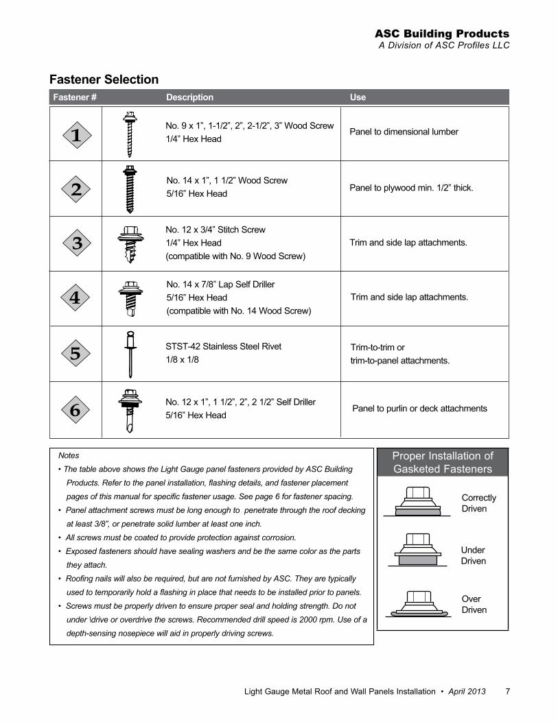
no . 9 x 1”, 1-1/2”, 2”, 2-1/2”, 3” Wood Screw 1/4” Hex Head
Panel to dimensional lumber
Panel to plywood min . 1/2” thick .
trim and side lap attachments .
trim and side lap attachments .
trim-to-trim or trim-to-panel attachments .
Panel to purlin or deck attachments
no . 14 x 1”, 1 1/2” Wood Screw5/16” Hex Head
no . 12 x 3/4” Stitch Screw1/4” Hex Head (compatible with no . 9 Wood Screw)
no . 14 x 7/8” lap Self driller5/16” Hex Head(compatible with no . 14 Wood Screw)
StSt-42 Stainless Steel Rivet1/8 x 1/8
no . 12 x 1”, 1 1/2”, 2”, 2 1/2” Self driller5/16” Hex Head
Fastener # Description Use
Fastener Selection
Notes
• The table above shows the Light Gauge panel fasteners provided by ASC Building
Products. Refer to the panel installation, flashing details, and fastener placement
pages of this manual for specific fastener usage. See page 6 for fastener spacing.
• Panel attachment screws must be long enough to penetrate through the roof decking
at least 3/8”, or penetrate solid lum ber at least one inch.
• All screws must be coated to provide protection against corrosion.
• Exposed fasteners should have sealing washers and be the same color as the parts
they attach.
• Roofing nails will also be required, but are not furnished by ASC. They are typically
used to temporarily hold a flashing in place that needs to be installed prior to panels.
• Screws must be properly driven to ensure proper seal and holding strength. Do not
under \drive or overdrive the screws. Recommended drill speed is 2000 rpm. Use of a
depth-sensing nosepiece will aid in properly driving screws.
Proper Installation of gasketed fasteners
Correctlydriven
Underdriven
overdriven
8 April 2013 www.ascbp.com
Light Gauge Metal Roof and Wall Panels Installation Guide for Delta Rib, Delta Rib III, Nor-Clad®, Strata Rib® & 2½ Corrugated
1" 1"
ASC'S LIGHTGAUGE ROOFING
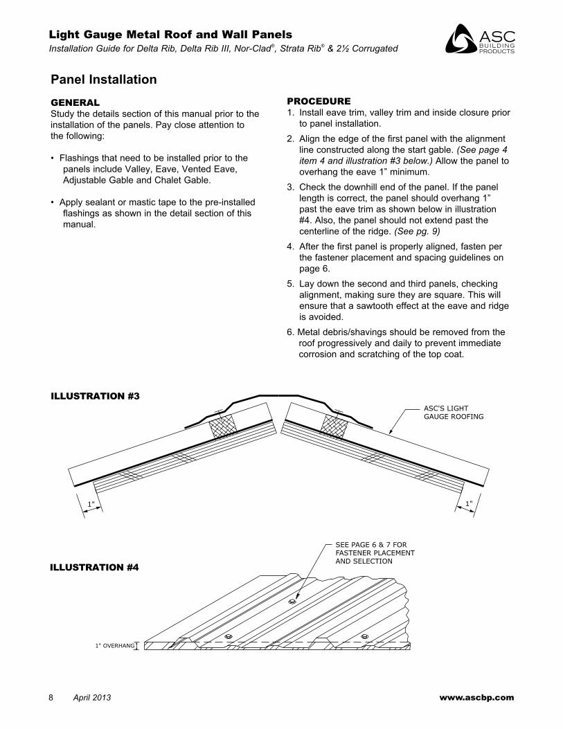
Panel InstallationGENERALStudy the details section of this manual prior to the installation of the panels . Pay close attention to the following:
• flashings that need to be installed prior to the panels include Valley, eave, Vented eave, Adjustable gable and Chalet gable .
• Apply sealant or mastic tape to the pre-installed flashings as shown in the detail section of this manual .
SEE PAGE 6 & 7 FORFASTENER PLACEMENTAND SELECTION
1" OVERHANG
ILLUSTRATION #3
ILLUSTRATION #4
PROCEDURE1 . Install eave trim, valley trim and inside closure prior
to panel installation .2 . Align the edge of the first panel with the alignment
line constructed along the start gable . (See page 4 item 4 and illustration #3 below.) Allow the panel to overhang the eave 1” minimum .
3 . Check the downhill end of the panel . If the panel length is correct, the panel should overhang 1” past the eave trim as shown below in illustration #4 . Also, the panel should not extend past the centerline of the ridge . (See pg. 9)
4 . After the first panel is properly aligned, fasten per the fastener placement and spacing guidelines on page 6 .
5 . lay down the second and third panels, checking alignment, making sure they are square . this will ensure that a sawtooth effect at the eave and ridge is avoided .
6 . Metal debris/shavings should be removed from the roof progressively and daily to prevent immediate corrosion and scratching of the top coat .

light gauge Metal Roof and Wall Panels Installation • April 2013 9
ASC Building ProductsA Division of ASC Profiles LLC
2"
1 7/8"
3/4"
1/2"
1/2"3/8" HEM
7"7"
2 1/8"
UNIVERSAL RIDGE (R1)
2. #14 WOOD SCREW SEE ILLUSTRATION ON PAGE 7
TOP POLYETHYLENE CLOSURE SET IN SEALANT ALL AROUND (SEE PROCEDURES)
ASC'S LIGHTGAUGE ROOFING
3. #12 x 3/4" STITCH SCREWOR
4. #14 x 7/8" LAP SELF DRILLER @ EACH RIB OR 8" O.C. FOR CORRUGATED
3-3/4"
3-1/2"
1/2"135º TYP.
3/8" HEM
Hip/Ridge Flashing
Procedures• Caulk the bottom and sides of the polyethylene
closure . Set the closure as shown above and caulk the top . the closure is optional if the panel is turned up and caulked at the sides near the rib .
• fasten the ridge cap using stitch screw at each rib or 8” o .c . for corrugated .
• Close the ends of the universal ridge cap by cutting and folding material at each end . fasten with rivets . (see page 10)
• Caulk, lap and rivet sequential ridge flashings . (see pg. 44) .
R1 R3 R4
Note: “R1” is a universal hip/ridge. A standard hip/ridge, “R3 & R4”, is also available.
Note: The gable flashing must be installed prior to installation of the ridge (see page 18).

10 April 2013 www.ascbp.com
Light Gauge Metal Roof and Wall Panels Installation Guide for Delta Rib, Delta Rib III, Nor-Clad®, Strata Rib® & 2½ Corrugated
Universal Ridge Termination
UNIVERSAL RIDGE (R1)
BUTYL MASTIC TAPEOR NEOPRENE CLOSUREREMNANTS TO CLOSEOFF THE RIDGE
3. STITCH SCREW 1/2"FROM EDGE OF GABLE
GABLE
CAULK AND RIVET
SEE PAGE 21 FORGABLE PREPARATION
OVERHANG UP TO 4"THEN FIELD TRIM TO1" USING SNIPS OR SHEAR
1"

light gauge Metal Roof and Wall Panels Installation • April 2013 11
ASC Building ProductsA Division of ASC Profiles LLC
1 7/8"
6 3/4" 6 3/4"
3/8" HEM
1 7/8"1 1/8"
1 1/8"3/8" HEM
SCREEN BY OTHERSVENTED RIDGE (R2)
ASC'S LIGHTGAUGE ROOFING
2"
TOP CLOSURE
C-METAL (C1)
2. #14 WOOD SCREW SEE ILLUSTRATION ON PAGE 7
3. #12x3/4" STITCH SCREWOR
4. #14x7/8" LAP SELF DRILLER@ EACH RIB OR 8" O.C.FOR CORRUGATED
AIR
FLOW
7/8"
2”
1”
3/8" HEM
Vented Ridge/Hip Flashing
Procedures• Plywood should be held back 2” from each side of the
ridge .• Attach the screen at each panel rib sandwiching the top
closure in place . ensure screen is pulled tight to avoid sagging .
• fasten the vented ridge using stitch screw at each rib or 8” o .c . for corrugated .
• Caulk, lap and rivet sequential flashings . (see pg. 44).
• Close the ends of the ridge cap by cutting and folding material at each end . fasten with rivets and caulking joints . (see pg. 12).
• Slopes greater than 6:12 may require special ridge dimensions .
R2 C1
Note: The gable flashing must be installed prior to installation of the ridge (see page 18).
The screening shown creates a barrier for insects and birds while allowing for ventilation.
For snow and heavy rain environments, please inquire about optional Vented Ridge details.

12 April 2013 www.ascbp.com
Light Gauge Metal Roof and Wall Panels Installation Guide for Delta Rib, Delta Rib III, Nor-Clad®, Strata Rib® & 2½ Corrugated
Vented Ridge/Hip Termination
CUT AND TRIM SIMILARTO GABLE (SEE PAGE 21).
FOLD DOWN OVER END TABS.
CUT AT BENDS 1"AND FOLD IN 90˚
VENTED RIDGE (R2)
CAULK
CAULK AND RIVET
GABLE
SEE GABLE PREPARATION@ RIDGE (PAGE 21)

light gauge Metal Roof and Wall Panels Installation • April 2013 13
ASC Building ProductsA Division of ASC Profiles LLC
2"3"
4"2" 2"
1"
13" 13"
'W' VALLEY (V1)
2 ROWS BUTYL MASTIC TAPE
ASC'S LIGHTGAUGE ROOFING
2. #14 WOOD SCREW SEE ILLUSTRATION ON PAGE 7
INSTALL EMSEAL CLOSURES DIAGONALLY ACROSS THE BOTTOM SIDE OF THE PANEL AND SET IN SEALANT ALL AROUND
SEE NOTE
BELOW
1" TYP
IF PAINTED,THIS SIDE
19-7/16"19-7/16"
Valley Flashing
V1 V2
Procedures• Place a second layer of 36” roof felt in the valley
center line with 18” of roof felt on each side .• Starting at the low end, trim and place the valley
flashing so it overhangs the eaves 1” . (see pg. 14)• Caulk and lap the subsequent valley flashings a
minimum of 8” .• Parallel to the valley, place two rows of 1/2” butyl
mastic tape sealant spaced as shown .• the polyethylene closures cannot be installed diagonally
across a panel . At mitre cuts, use emseal closures at a right angle to the panel ribs .
• field cut the panels holding a minimum of 4” back from the valley as shown . larger valleys without the center “V”, may be required in snow country installations .
• Attach the panels to the roof and ‘thru-fasten’ along the bottom end using a #14 x 1” woodscrew
at 8” up from the valley aligned with the second row of butyl mastic tape .
• When valleys are required, install sidelap neoprene mastic tape along the sidelap a minimum of 10’-0” up from the panel edge .
Note: In areas where snow, ice and heavy rain con-ditions exist, panels may need to be held back more than 4” and the valley flashing overall width must be increased. A high temperature cold-applied rubberized underlayment should be used extending at least 3’ up from the center of the valley on each side.
14 April 2013 www.ascbp.com
Light Gauge Metal Roof and Wall Panels Installation Guide for Delta Rib, Delta Rib III, Nor-Clad®, Strata Rib® & 2½ Corrugated
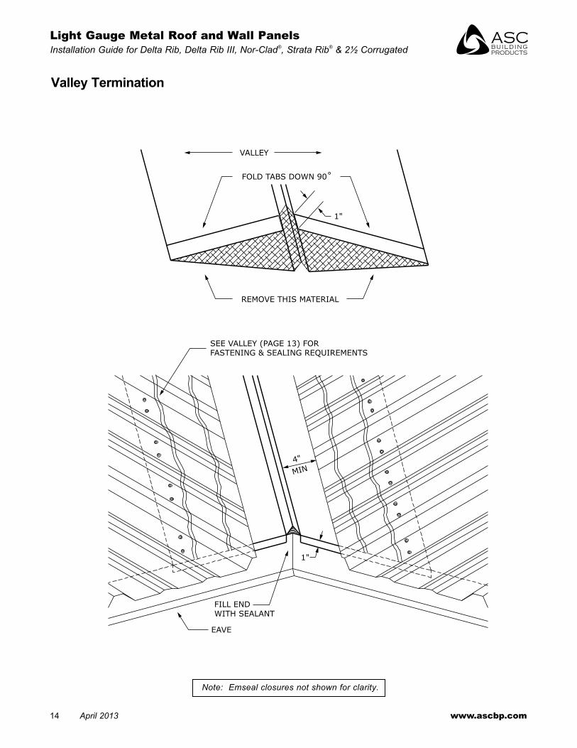
1"
1"
4"
MIN
VALLEY
FOLD TABS DOWN 90˚
REMOVE THIS MATERIAL
SEE VALLEY (PAGE 13) FORFASTENING & SEALING REQUIREMENTS
EAVE
FILL ENDWITH SEALANT
Valley Termination
Note: Emseal closures not shown for clarity.

light gauge Metal Roof and Wall Panels Installation • April 2013 15
ASC Building ProductsA Division of ASC Profiles LLC
ASC'S LIGHTGAUGE ROOFING
2. #14 WOOD SCREW SEE ILLUSTRATION ON PAGE 7
1"O.H.
2X BLOCKING
PERFORATEFASCIA ASREQUIRED
EAVE (E1)
BOTTOM POLYETHYLENE CLOSURE SET IN SEALANT ALL AROUND
ROOFING NAILS@ 24" O.C.
1/2"
1 3/8"
1 3/8"
2"
1/2"
3/8" HEM
3-3/8"4-3/8"
3/8" HEM
1/2"
3"
2"
1/2"
3"
1/2"
3"
1/2"
4 3/8"
2"
1 1/2"
1/2"
3"
2"
Procedures• Carpentry must be completed as indicated prior to
installation of the Vented eave .• Attach the eave flashing using roofing nails evenly
spaced at 24” o .c .
• Caulk and lap the flashing a minimum of 3” . (see pg. 44)
• Panels should overhang the eave 1” minimum .
Eave and Vented Eave Flashingsthis flashing must be installed prior to the panels .
ER1 ER2
E2E1 E4 E5E3
Vented Eave
16 April 2013 www.ascbp.com
Light Gauge Metal Roof and Wall Panels Installation Guide for Delta Rib, Delta Rib III, Nor-Clad®, Strata Rib® & 2½ Corrugated
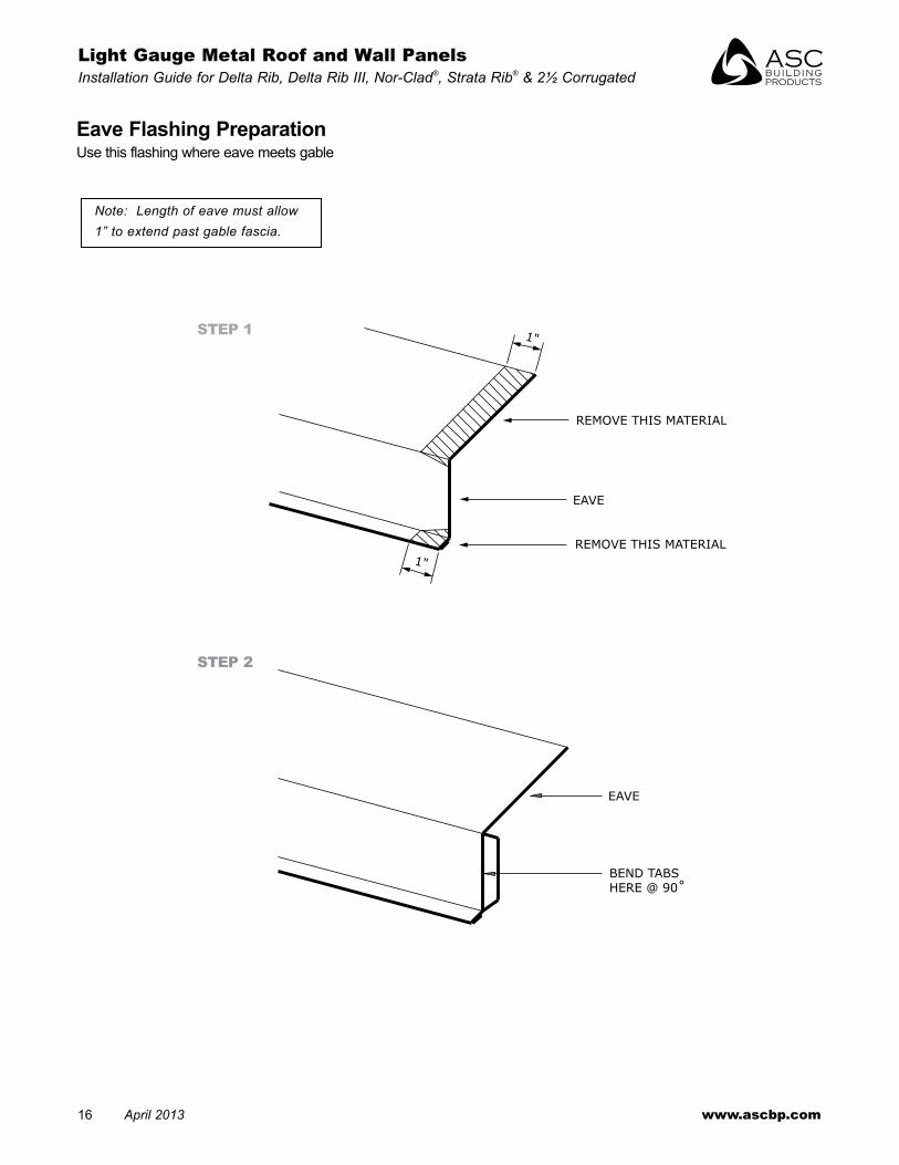
1"
1"
REMOVE THIS MATERIAL
EAVE
REMOVE THIS MATERIAL
EAVE
BEND TABSHERE @ 90˚
Eave Flashing PreparationUse this flashing where eave meets gable
STEP 1
STEP 2
Note: Length of eave must allow 1” to extend past gable fascia.

light gauge Metal Roof and Wall Panels Installation • April 2013 17
ASC Building ProductsA Division of ASC Profiles LLC
Gutter and Vented Gutter Flashingsnote: this flashing must be installed prior to the panels .
Procedures• felt should go over top of eave (e3)
(felt not shown) .• Carpentry must be complete as indicated prior to
installation of the Vented gutter .• Attach eave flashing using roofing nails evenly spaced
at 24” o .c .
• Caulk and lap the flashing a minimum of 3” . (see pg. 44)
• Panels should overhang the eave a minimum of 1” .• ASC Building Products recommends that a
licensed gutter contractor install gutters .
Vented Gutter
1 3/8"
1 3/8"
1/2"
ROOFING NAILS@ 24" O.C.
2. #14 WOOD SCREW SEE ILLUSTRATION ON PAGE 7
1"O.H.
PERFORATEFASCIA ASREQUIRED
2X BLOCKING@ 12" O.C.
BOTTOM POLYETHYLENECLOSURE SET IN SEALANT
GUTTER
ATTACH PERMANUFACTURER'SRECOMMENDATIONS
METAL SCREENAS REQUIRED
EAVE (E3)
MASTIC TAPE, TOP & BOTTOM
E3

18 April 2013 www.ascbp.com
Light Gauge Metal Roof and Wall Panels Installation Guide for Delta Rib, Delta Rib III, Nor-Clad®, Strata Rib® & 2½ Corrugated
5" 5/8"
3/8" HEM
4"
5/8"
3/8" HEM
1 1/8"
1/2"
2 3/4"
4"
1/2"
1 1/4"
BUTYL MASTIC TAPE
2. #14 WOOD SCREW @ 24" O.C.
ASC'S LIGHT GAUGE ROOFING
3. #12 x 3/4" STITCH SCREWOR
4. #14 x 7/8" LAP SELF DRILLER @ 24" O.C.
GABLE (G2)
2. #14 x 1" METAL WOOD @ 24" O.C.
2"
1-1/8"
3/8" HEM
5/8"4"
3/8" HEM1/2"
Gable Flashing
5" 5/8"
3/8" HEM
4"
5/8"
3/8" HEM
1 1/8"4"
1/2" 1/2"
2"3/8"
2 3/4"
4"
1/2"
1 1/4"
BUTYL MASTIC TAPE
2. #14 WOOD SCREW@ 24" O.C.
ASC'S LIGHT GAUGE ROOFING
3. #12 x 3/4" STITCH SCREWOR
4. #14 x 7/8" LAP SELF DRILLER@ 24" O.C.
GABLE (G4)
2. #14 x 1" METAL WOOD@ 24" O.C.
G1
G3 G4
Procedures• Place the first roof panel according to the
instructions on pages 4 and 8 .• Place butyl mastic tape along the top of the panel
rib as shown .• Install the gable flashing by placing it firmly over the
rib . Use stitch screws to fasten flashing to the panel and use color matched woodscrews at 24” o .c . to fasten flashing to structure .
• Caulk and lap the flashing a minimum of 3” . (see pg. 44)
• Mitre cut the flashing at the peak to join each side at the ridge . (see pg. 21)
• Snip and fold the gable at the eave to close the end . Use rivets to fasten .
Notes: “G1” is a standard gable. Narrower gables, “G3” and “G4”, are also available.

light gauge Metal Roof and Wall Panels Installation • April 2013 19
ASC Building ProductsA Division of ASC Profiles LLC
Gable/Ridge Transition(similar to endwall)
ASC'S LIGHTGAUGE ROOFING
GABLE OR SIDEWALL
2" BUTYL MASTIC TAPEWITH FASTENERS @ 2" O.C.
RIDGE OR ENDWALL
GABLE
BEND HERE 90˚
RIVET
INSERT EAVE TABBEHIND GABLE
EAVE
ASC'S LIGHTGAUGE ROOFING
GABLE OR SIDEWALL
2" BUTYL MASTIC TAPEWITH FASTENERS @ 2" O.C.
RIDGE OR ENDWALL
GABLE
BEND HERE 90˚
RIVET
INSERT EAVE TABBEHIND GABLE
EAVE
Gable Corner at Eave

20 April 2013 www.ascbp.com
Light Gauge Metal Roof and Wall Panels Installation Guide for Delta Rib, Delta Rib III, Nor-Clad®, Strata Rib® & 2½ Corrugated
Gable Flashing Preparation
STEP 1
STEP 2
STEP 3
GABLE
REMOVE THIS MATERIAL
* SEE TABLEFOR DIMENSION
GABLE
SNIP HERE
REMOVE THIS MATERIAL
2 1/
2"
1 1/
2"
1 1/2"SNIP HERE
1"
1"
GABLE
FOLD 90˚
REMOVE THIS MATERIAL
GABLE
REMOVE THIS MATERIAL
* SEE TABLEFOR DIMENSION
GABLE
SNIP HERE
REMOVE THIS MATERIAL
2 1/
2"
1 1/
2"
1 1/2"SNIP HERE
1"
1"
GABLE
FOLD 90˚
REMOVE THIS MATERIAL
Roof Pitch Dimension3:12 2”4:12 17⁄8”5:12 111⁄16”6:12 16⁄16”12:12 5⁄8”
Note: Length of uncut gable must extend 2 1/2” past eave fascia.

light gauge Metal Roof and Wall Panels Installation • April 2013 21
ASC Building ProductsA Division of ASC Profiles LLC
EQUALEQUAL
VERTICAL CUT
* SEE TABLEREMOVE THISMATERIAL WITH SNIPS
OR POWER SHEARS
REMOVE THIS MATERIAL WITH SNIPSOR POWER SHEARS
RIDGE LINE
14" @ STANDARD RIDGE
17" @ VENTED RIDGE
RIDGE LINE
GABLE
RIVET
GABLE
REMOVE THISMATERIAL WITH SNIPSOR POWER SHEARS
EQUALEQUAL
VERTICAL CUT
* SEE TABLEREMOVE THISMATERIAL WITH SNIPS
OR POWER SHEARS
REMOVE THIS MATERIAL WITH SNIPSOR POWER SHEARS
RIDGE LINE
14" @ STANDARD RIDGE
17" @ VENTED RIDGE
RIDGE LINE
GABLE
RIVET
GABLE
REMOVE THISMATERIAL WITH SNIPSOR POWER SHEARS
Gable Flashing Preparation at Ridge
STEP 1 STEP 2
STEP 3 STEP 4
Roof Pitch Dimension*3:12 11⁄16”
3 .5:12 11⁄4”4:12 17⁄16”5:12 13⁄4”6:12 23⁄16”12:12 47⁄16”
* Dimensions only apply to G4 Gable Flashing

22 April 2013 www.ascbp.com
Light Gauge Metal Roof and Wall Panels Installation Guide for Delta Rib, Delta Rib III, Nor-Clad®, Strata Rib® & 2½ Corrugated
2. #14 WOOD SCREW SEE ILLUSTRATION ON PAGE 7
PEAK (PF2)
2. #14 x 1" WOOD SCREW @ 24" O.C.
TOP POLYETHYLENE CLOSURE SET IN SEALANT ALL AROUND
3. #12 x 3/4" STITCH SCREWOR
4. #14 x 7/8" LAP SELF DRILLER @ EACH RIB OF 8" O.C. FOR CORRUGATED
ASC'S LIGHTGAUGE ROOFING
6"
1/2"
3/8" HEM
3/8" HEM
5"
Peak Flashing
PF2
Procedures:• Caulk the bottom and sides of the polyethylene
closure . Set the closure as shown above and caulk the top . the closure is optional if the panel is turned up and caulked at the sides near the rib .
• fasten the peak flashing as shown above .• Caulk and lap the flashing a minimum of 3” .
(see pg. 44).

light gauge Metal Roof and Wall Panels Installation • April 2013 23
ASC Building ProductsA Division of ASC Profiles LLC
4"
1 1/8"
2"
1/2"
1/2"
3/4"
ASC'S LIGHTGAUGE WALL PANEL
ROOFING NAILS@ 24" O.C.
2. #14 x 1" WOOD SCREW SEE ILLUSTRATION ON PAGE 7
BOTTOM POLYETHYLENE CLOSURESET IN SEALANT ALL AROUND
UNIVERSAL SIDEWALL (SW1)
BUTYL MASTIC TAPE
ASC'S LIGHTGAUGE ROOFING
2. #14 WOOD SCREW @ 24" O.C.
1-1/8"
3/8" HEM5/8"
3"
4"
Sidewall Flashingthis flashing must be installed prior to wall panels .
SW1 SW2
Procedures• the roof should be installed prior to the siding .• Place butyl mastic tape along the top of the panel
as shown .• Install the side wall flashing by placing it firmly on
the roofing panel and fastening with the fastener indicated .
• Caulk and lap the flashing a minimum of 3” . (see pg. 44)
24 April 2013 www.ascbp.com
Light Gauge Metal Roof and Wall Panels Installation Guide for Delta Rib, Delta Rib III, Nor-Clad®, Strata Rib® & 2½ Corrugated
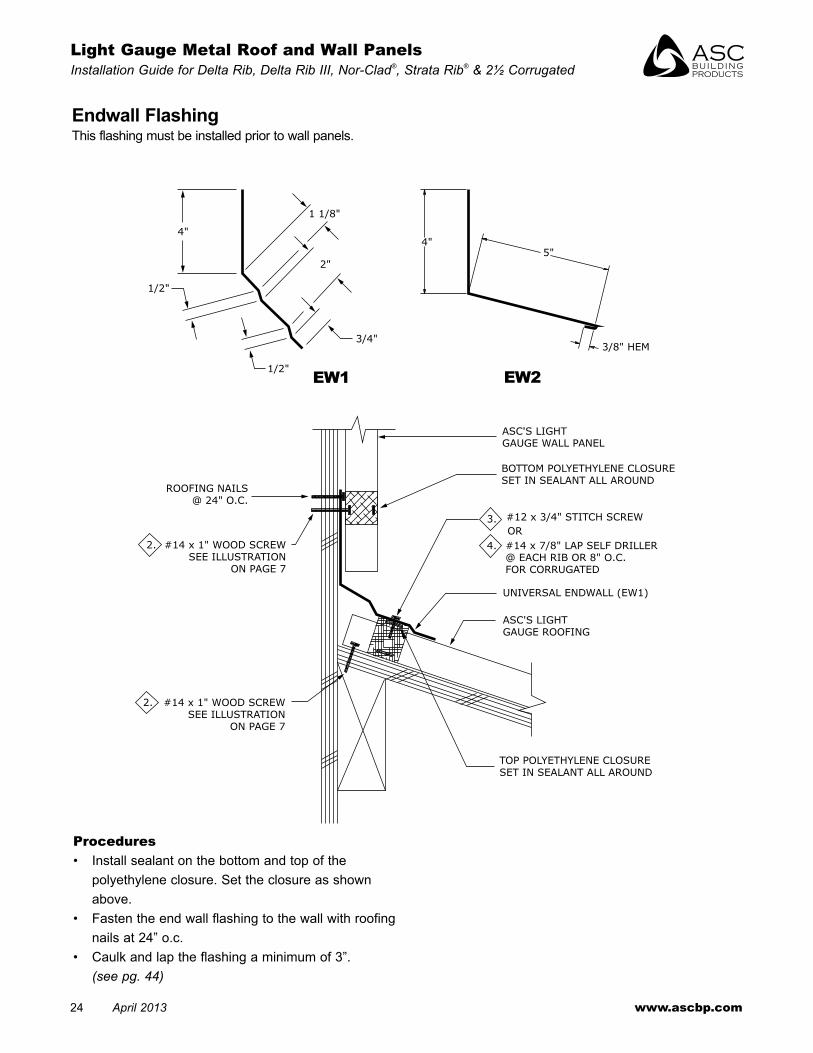
4"
1/2"
1 1/8"
2"
3/4"
1/2"
ROOFING NAILS@ 24" O.C.
2. #14 x 1" WOOD SCREWSEE ILLUSTRATION
ON PAGE 7
ASC'S LIGHTGAUGE WALL PANEL
BOTTOM POLYETHYLENE CLOSURE SET IN SEALANT ALL AROUND
3.
4.
#12 x 3/4" STITCH SCREW
#14 x 7/8" LAP SELF DRILLER@ EACH RIB OR 8" O.C.FOR CORRUGATED
OR
UNIVERSAL ENDWALL (EW1)
ASC'S LIGHTGAUGE ROOFING
TOP POLYETHYLENE CLOSURE SET IN SEALANT ALL AROUND
2. #14 x 1" WOOD SCREWSEE ILLUSTRATION
ON PAGE 7
3/8" HEM
5"4"
EW1 EW2
Procedures• Install sealant on the bottom and top of the
polyethylene closure . Set the closure as shown above .
• fasten the end wall flashing to the wall with roofing nails at 24” o .c .
• Caulk and lap the flashing a minimum of 3” . (see pg. 44)
Endwall Flashingthis flashing must be installed prior to wall panels .

light gauge Metal Roof and Wall Panels Installation • April 2013 25
ASC Building ProductsA Division of ASC Profiles LLC
Vented End Wall Flashingthis flashing must be installed prior to wall panels .
Procedures• Plywood should be held back 2” from the wall .• Install sealant on the bottom and top of the
polyethylene closure . Set the closure as shown above .• fasten the end wall flashing to the wall with roofing
nails at 24” o .c . max .• fasten the flashing to each rib with #12 x 3/4” stitch
screws . Place a small length of sealant on top of each rib as shown .
• Caulk and lap the flashing a minimum of 3” . (see pg. 44)
• for Profile Vent, use (eW1) for vented endwall flashing detail .
6 3/4"
1 7/8"
3/8" HEM
1 1/8"
4"
2"
ASC'S LIGHTGAUGE WALL PANEL
BOTTOM POLYETHYLENE CLOSURE SET IN SEALANT ALL AROUND
VENTED ENDWALL (EW17)
BUTYL MASTIC TAPEASC'S LIGHT GAUGE ROOFING
3. #12 x 3/4" STITCH SCREWOR
4. #14 x 7/8" LAP SELF DRILLER @ EACH RIB OR 8" O.C. FOR CORRUGATED
AIR FL
OW
SCREEN BY OTHERS
TOP POLYETHYLENE CLOSURE SET IN SEALANT ALL AROUND
ROOFING NAILS@ 24" O.C.
2. #14 x 1" WOOD SCREW SEE ILLUSTRATION ON PAGE 7
OPTIONAL FIBER FILLFOR SNOW COUNTRY
2. #14 WOOD SCREW SEE ILLUSTRATION ON PAGE 7
EW17
26 April 2013 www.ascbp.com
Light Gauge Metal Roof and Wall Panels Installation Guide for Delta Rib, Delta Rib III, Nor-Clad®, Strata Rib® & 2½ Corrugated
ROOFING NAILS@ 24" O.C.
2. #14 WOOD SCREW SEE ILLUSTRATION ON PAGE 7
ROW OF BUTYL MASTIC TAPE
BOTTOM POLYETHYLENE CLOSURE SET IN SEALANT ALL AROUND
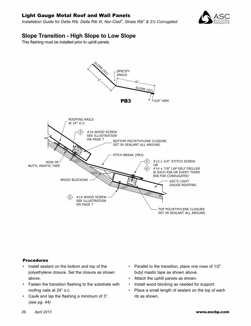
PITCH BREAK (PB3)
3. #12 x 3/4" STITCH SCREWOR
4. #14 x 7/8" LAP SELF DRILLER @ EACH RIB OR EVERY THIRD RIB FOR CORRUGATED
ASC'S LIGHTGAUGE ROOFING
TOP POLYETHYLENE CLOSURE SET IN SEALANT ALL AROUND
2. #14 WOOD SCREW SEE ILLUSTRATION ON PAGE 7
WOOD BLOCKING
3/8" HEM
SLOPE (S1)
SLOPE (S2)
6"5"
SPECIFYANGLE
Slope Transition - High Slope to Low Slopethis flashing must be installed prior to uphill panels .
Procedures• Install sealant on the bottom and top of the
polyethylene closure . Set the closure as shown above .
• fasten the transition flashing to the substrate with roofing nails at 24” o .c .
• Caulk and lap the flashing a minimum of 3” . (see pg. 44)
• Parallel to the transition, place one rows of 1/2” butyl mastic tape as shown above .
• Attach the uphill panels as shown .• Install wood blocking as needed for support .• Place a small length of sealant on the top of each
rib as shown .
PB3
light gauge Metal Roof and Wall Panels Installation • April 2013 27
ASC Building ProductsA Division of ASC Profiles LLC
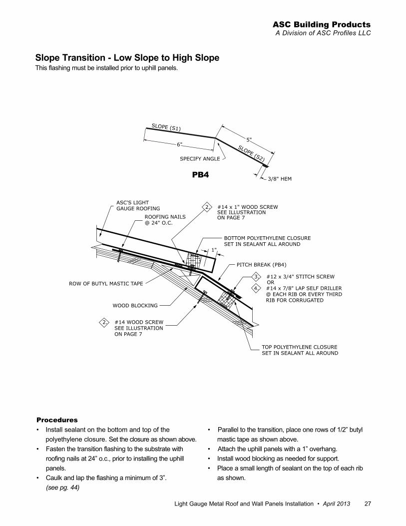
1"
ASC'S LIGHTGAUGE ROOFING
ROOFING NAILS@ 24" O.C.
2. #14 x 1" WOOD SCREW SEE ILLUSTRATION ON PAGE 7
PITCH BREAK (PB4)
BOTTOM POLYETHYLENE CLOSURE SET IN SEALANT ALL AROUND
TOP POLYETHYLENE CLOSURE SET IN SEALANT ALL AROUND
ROW OF BUTYL MASTIC TAPE
WOOD BLOCKING
2. #14 WOOD SCREW SEE ILLUSTRATION ON PAGE 7
3. #12 x 3/4" STITCH SCREWOR
4. #14 x 7/8" LAP SELF DRILLER @ EACH RIB OR EVERY THIRD RIB FOR CORRUGATED
SLOPE (S1)
SLOPE (S2)
5"6"
3/8" HEM
SPECIFY ANGLE
Slope Transition - Low Slope to High Slopethis flashing must be installed prior to uphill panels .
Procedures• Install sealant on the bottom and top of the
polyethylene closure . Set the closure as shown above .• fasten the transition flashing to the substrate with
roofing nails at 24” o .c ., prior to installing the uphill panels .
• Caulk and lap the flashing a minimum of 3” . (see pg. 44)
• Parallel to the transition, place one rows of 1/2” butyl mastic tape as shown above .
• Attach the uphill panels with a 1” overhang .• Install wood blocking as needed for support .• Place a small length of sealant on the top of each rib
as shown .
PB4

28 April 2013 www.ascbp.com
Light Gauge Metal Roof and Wall Panels Installation Guide for Delta Rib, Delta Rib III, Nor-Clad®, Strata Rib® & 2½ Corrugated
5"
3/8" HEM
3 7/8"
5/8"
3/4"
1 5/8"
6"
2 1/2"
BOTTOM POLYETHYLENECLOSURE SET IN SEALANTALL AROUND
ASC'S LIGHTGAUGE ROOFINGSLOPE
2. #14 WOOD SCREW SEE ILLUSTRATION ON PAGE 7
ROW OF MASTIC TAPE
* THIS FLASHING IS ALSO KNOWN ASA "PROW" OR "DUTCH" GABLE ROOF.
CHALET GABLE (G18)
2. #14 x 1" WOOD SCREW @ 24" O.C.
Chalet Gable Flashingthis flashing must be installed prior to panels .
Procedures• Attach the chalet flashing using color matched
woodscrews spaced at 24” o .c .• Parallel to the face of the flashing, place 1/2” butyl
mastic tape as shown .• the polyethylene closures cannot be installed diagonally
across a panel . At mitre cuts, use emseal closures at a right angle to the panel ribs .
• field cut the panels holding 5” back from the face of the flashing as shown .
• Attach the panels to the roof and ‘thru-fasten’ along the bottom edge using #14-10 woodscrews with washer evenly spaced at 4” o .c . and at approximately 7 1/2” in from the face of the flashing so they align with the second row of tape sealant .
• Chalet gable to be used with standard eave “e1” . (see pg. 15)
G18
End of mitre-cut panel (See Roof Map pg. 5)

light gauge Metal Roof and Wall Panels Installation • April 2013 29
ASC Building ProductsA Division of ASC Profiles LLC
3/8" HOOK
6"
1/2"
4"
1" HOOK
2 1/2"
ASC'S LIGHTGAUGE ROOFING
ADJUSTMENT AREA
2. #14 WOOD SCREW SEE ILLUSTRATION ON PAGE 7
ROOFING NAILS@ 12" O.C.
STARTER STRIP (SS1)
FIELD CAULK
2. #14 x 1" WOOD SCREW @ 24" O.C.
ADJUSTABLE GABLE (G5)
Adjustable Gable Flashing
G5 SS1
Procedures• In many instances, the roof sheet will have to be field
modified (major rib removed along the gable) . See roof map on page 5 and locate “adjustable gable” . If gable trims are used in this location, and as the roof drains from the ridge, water will flow inside the gable trims shown on page 17 . the adjustable gable trim pieces shown above can assist in a proper roof in stal la tion .
• When a major rib on a light gauge panel occurs over the roof area within 3” of the edge of the gable, cut the panel and remove the major rib from the end of the sheet from the low eave to allow for the placement of the starter strip .
• Install the gable trim, extending the horizontal leg 6” uphill and underneath the eave on the portion of the roof sheet at the gable/eave intersection .
• locate the placement of the starter strip to insure that the cut edge of the roof sheet can be inserted into the 1” leg of the starter strip .
• field caulk inside the open hem and the under side of the starter strip per the detail on this page and install parallel to gable .
Note: Locate starter strip to allow proper installation of adjustable gable trim as shown.

30 April 2013 www.ascbp.com
Light Gauge Metal Roof and Wall Panels Installation Guide for Delta Rib, Delta Rib III, Nor-Clad®, Strata Rib® & 2½ Corrugated
Vent Flashing
Procedures• trim the opening in the flashing to 20% smaller
than the pipe diameter .• Slide the flashing down over the pipe .• Seal between the vent flashing and the roofing with
gunnable caulk and set the flashing .• form the flashing to fit the profile of the roof .• fasten the flashing with fasteners at 1” o .c . Refer to
the fastener selection guide on page 7 .• Penetrations occurring over spaced supports
require additional support framing .• A stainless steel draw band should be installed at
the top of the vent/pipe flashing .
• A minimum drainage area of 2” should be‚ maintained between the base of the flexible vent/pipe flashing and the roof panels’ major ribs .
• When a penetration occurs through a nor-Clad® panel sidelap, gunnable caulk needs to be installed in the capillary groove from the penetration to the ridge . this will prevent water from running downhill in the capillary groove and into the roof opening . Refer to illustration #5, above .
VENT / PIPE FLASHING
FASTEN @ 1" O.C.
NOR-CLADROOF PANEL
GUNNABLE CAULKIN CAPILLARY GROOVE
SEE PROCEDURES BELOW
ILLUSTRATION #5
Note: For the best drainage when a square-based pipe flashing is used, one corner of the flexible pipe flashing should be oriented to the high-side of the roof.
light gauge Metal Roof and Wall Panels Installation • April 2013 31
ASC Building ProductsA Division of ASC Profiles LLC
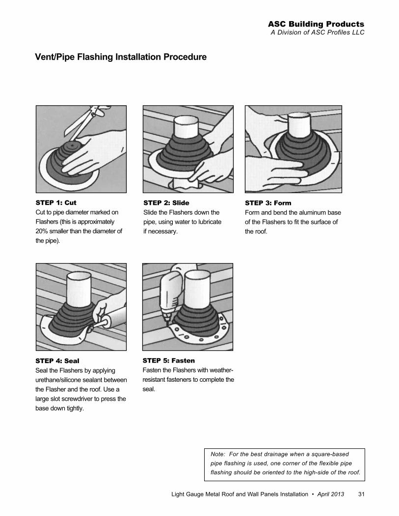
Vent/Pipe Flashing Installation Procedure
STEP 1: CutCut to pipe diameter marked on flashers (this is approximately 20% smaller than the diameter of the pipe) .
STEP 2: SlideSlide the flashers down the pipe, using water to lubricate if necessary .
STEP 4: SealSeal the flashers by applying urethane/silicone sealant between the flasher and the roof . Use a large slot screwdriver to press the base down tightly .
STEP 5: Fastenfasten the flashers with weather-resistant fasteners to complete the seal .
STEP 3: Formform and bend the aluminum base of the flashers to fit the surface of the roof .
Note: For the best drainage when a square-based pipe flashing is used, one corner of the flexible pipe flashing should be oriented to the high-side of the roof.

32 April 2013 www.ascbp.com
Light Gauge Metal Roof and Wall Panels Installation Guide for Delta Rib, Delta Rib III, Nor-Clad®, Strata Rib® & 2½ Corrugated
DOWNHILLSEE PAGE 34
UPHILLSEE PAGE 33
SIDESEE BELOW1.
2.
3.
SLOPE
LENGTH WIDTH
3 1/2"
2"
3/8" HEM
3.
DOWNHILLSEE PAGE 37
WIDTHLENGTH
SLOPE
1.
SIDESEE BELOW
2.
UPHILLSEE PAGE 36
SIDE SKYLIGHT (SK18)
2. #14 WOOD SCREW @ 4" O.C.BUTYL MASTIC TAPEASC'S LIGHTGAUGE ROOFING
Skylight Flashing
• Wherever possible, position the skylight curb so the ribs of the roof panels do not interfere with the flashing .
• Cut the light gauge roof panels as close to the left, right and downhill sides of the curb as possible . Cut the uphill side 6” up from the curb as indicated above .
• Penetrations occurring over spaced supports require additional support framing .
SK18(Side)
1 – Skylight Flashing (Side)
Note: Do not fasten the panels within 24” uphill from the skylight until the penetration flashing is installed.
light gauge Metal Roof and Wall Panels Installation • April 2013 33
ASC Building ProductsA Division of ASC Profiles LLC
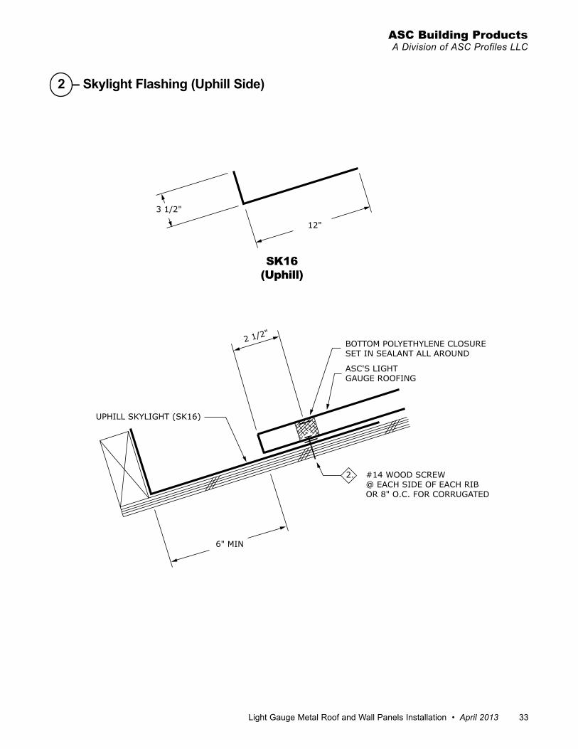
6" MIN
2 1/2"
3 1/2"
12"
BOTTOM POLYETHYLENE CLOSURE SET IN SEALANT ALL AROUND
ASC'S LIGHTGAUGE ROOFING
2. #14 WOOD SCREW @ EACH SIDE OF EACH RIB OR 8" O.C. FOR CORRUGATED
UPHILL SKYLIGHT (SK16)
SK16(Uphill)
2 – Skylight Flashing (Uphill Side)

34 April 2013 www.ascbp.com
Light Gauge Metal Roof and Wall Panels Installation Guide for Delta Rib, Delta Rib III, Nor-Clad®, Strata Rib® & 2½ Corrugated
5"
2 1/2"
3/8" HEM
3. #12 x 3/4" STITCH SCREW @ EACH RIB OR 8" O.C. FOR CORRUGATED
TOP POLYETHYLENE CLOSURE SET IN SEALANT ALL AROUND
DOWNHILL SKYLIGHT (SK17)
ASC'S LIGHTGAUGE ROOFING
2. #14 WOOD SCREW SEE ILLUSTRATION ON PAGE 7
SK17(Downhill)
3 – Skylight Flashing (Downhill Side)

light gauge Metal Roof and Wall Panels Installation • April 2013 35
ASC Building ProductsA Division of ASC Profiles LLC
6"
2 1/16"
2"
2"
2"
2"
2 1/
2"
SKYLIGHT
ASC'S LIGHTGAUGE ROOFING
SLOPE
LENGTH
SLOPE
FOLD HERE 90˚CUT HERE
CUT HERE
REMOVE THIS MATERIAL
CUT HERE
Procedure for the Installation of Skylight Flashings
DOWNHILL
ILLUSTRATION #6
Skylight Flashing Preparation
RIGHT SIDE
UPHILL
Trim and bend the right side skylight flashing as indicated. Trim the left side in a similar fashion.
The skylight flashing will be 4” wider than the width of the curb (2” on each side). Cut a 1/8” slot in the two uphill corners of the Light Gauge Roofing Panel slightly wider than 2”, so the uphill flashing can slide through the two slots. (See illustration #6).Adjustments to the horizontal leg dimension and length of slit may have to be modified depending on the location of the panels’ major rib.
36 April 2013 www.ascbp.com
Light Gauge Metal Roof and Wall Panels Installation Guide for Delta Rib, Delta Rib III, Nor-Clad®, Strata Rib® & 2½ Corrugated
2"
1"
1"
FOLD HERE 90˚
CUT HERE
REMOVE THIS MATERIAL
CUT HERE
FOLD HERE 90˚ REMOVE THIS MATERIAL
CUT HERE
REMOVE HEMTO FOLD LINE
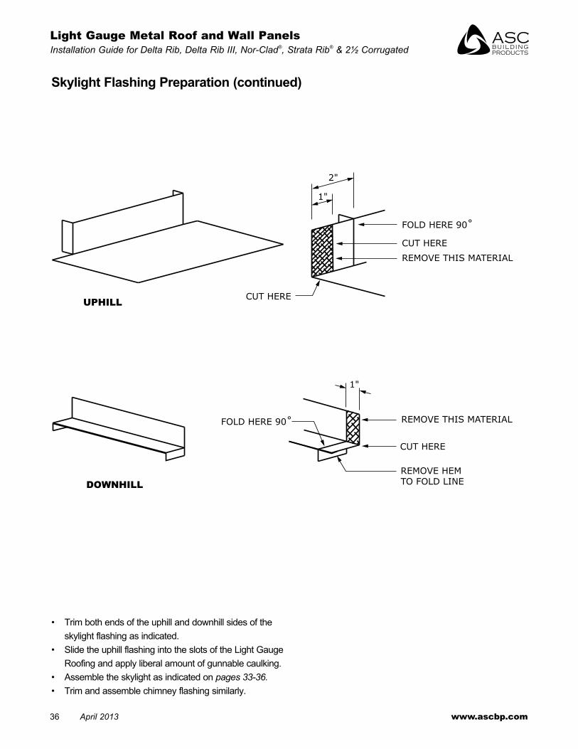
Skylight Flashing Preparation (continued)
• trim both ends of the uphill and downhill sides of the skylight flashing as indicated .
• Slide the uphill flashing into the slots of the light gauge Roofing and apply liberal amount of gunnable caulking .
• Assemble the skylight as indicated on pages 33-36.• trim and assemble chimney flashing similarly .
DOWNHILL
UPHILL

light gauge Metal Roof and Wall Panels Installation • April 2013 37
ASC Building ProductsA Division of ASC Profiles LLC
Chimney Flashing
3. 1.
2.
SLOPE
UPHILLSEE PAGE 39
DOWNHILLSEE PAGE 40
SIDESEE PAGE 38
1.
2.
3.
LENGTHWIDTH
SLOPE
Note: Procedures for the installation of chimney flash-ings are similar to the skylights. (see pgs. 33-36). The reglet** shown may be deleted if the chimney is clad with siding. (Lap the siding over the flashing and caulk). Be sure to specify the slope and the orientation of the chimney dimensions when ordering this assem-bly.** A reglet is a two-piece flashing found on the side of a wall, chimney or other similar roof penetration. (see flashing drawing pg. 40).

38 April 2013 www.ascbp.com
Light Gauge Metal Roof and Wall Panels Installation Guide for Delta Rib, Delta Rib III, Nor-Clad®, Strata Rib® & 2½ Corrugated
3/8" HEM
1/2"3"
3/8" HEM
3/4"3/8" HEM
6"
2"
GUNNABLE CAULK
ANCHOR BY OTHERS
REGLET (RG16)
GUNNABLE CAULK
SIDE CHIMNEY (CH18)
BUTYL MASTIC TAPE
ASC'S LIGHTGAUGE ROOFING
2. #14 WOOD SCREW @ 4" O.C.
CH18(Side)
RG16(Reglet)
1 – Chimney Flashing (Side)

light gauge Metal Roof and Wall Panels Installation • April 2013 39
ASC Building ProductsA Division of ASC Profiles LLC
6" MIN
2 1/2"
6"
12"
3/8" HEM
1/2" 3"
3/8" HEM
3/4"
GUNNABLE CAULK
ANCHORS BY OTHERS
REGLET (RG16)
GUNNABLE CAULK
UPHILLCHIMNEY(CH16)
BOTTOM POLYETHYLENE CLOSURE SET IN SEALANT ALL AROUND
ASC'S LIGHTGAUGE ROOFING
2. #14 WOOD SCREW@ EACH SIDE OF EACH RIBOR 8" O.C. FOR CORRUGATED
CH16(Side)
RG16(Reglet)
2 – Chimney Flashing (Uphill)
40 April 2013 www.ascbp.com
Light Gauge Metal Roof and Wall Panels Installation Guide for Delta Rib, Delta Rib III, Nor-Clad®, Strata Rib® & 2½ Corrugated
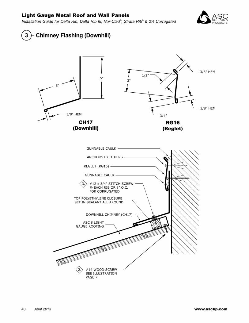
3/8" HEM
5"
5"3"
1/2"
3/4"
3/8" HEM
3/8" HEM
GUNNABLE CAULK
ANCHORS BY OTHERS
REGLET (RG16)
GUNNABLE CAULK
TOP POLYETHYLENE CLOSURE SET IN SEALANT ALL AROUND
DOWNHILL CHIMNEY (CH17)
ASC'S LIGHTGAUGE ROOFING
3. #12 x 3/4" STITCH SCREW @ EACH RIB OR 8" O.C. FOR CORRUGATED
2. #14 WOOD SCREW SEE ILLUSTRATION PAGE 7
CH17(Downhill)
RG16(Reglet)
3 – Chimney Flashing (Downhill)

light gauge Metal Roof and Wall Panels Installation • April 2013 41
ASC Building ProductsA Division of ASC Profiles LLC
Valley Top End
FIELD MITER AND ASSEMBLE
USE EMSEAL CLOSURETO CLOSE OFF VALLEY FLASHING
ASC'S LIGHTGAUGE ROOFING
ROOFING NAIL
2 ROWS OF BUTYLMASTIC TAPE
VALLEY (V1)
INSTALL EMSEAL CLOSURES DIAGONALLY ACROSS THE BOTTOM
SIDE OF THE PANEL AND SET IN SEALANT ALL AROUND

42 April 2013 www.ascbp.com
Light Gauge Metal Roof and Wall Panels Installation Guide for Delta Rib, Delta Rib III, Nor-Clad®, Strata Rib® & 2½ Corrugated
Valley Dormer
FIELD MITER AND ASSEMBLEONTO FLAT STOCK
USE EMSEAL CLOSURE TO CLOSE OFFVALLEY FLASHING
ASC'S LIGHTGAUGE ROOFING
ROOFING NAIL
2 ROWS OF BUTYLMASTIC TAPE
VALLEY (V1)
INSTALL EMSEAL CLOSURES DIAGONALLY ACROSS THE BOTTOM
SIDE OF THE PANEL AND SET IN SEALANT ALL AROUND

light gauge Metal Roof and Wall Panels Installation • April 2013 43
ASC Building ProductsA Division of ASC Profiles LLC
2. #14 WOOD SCREW SEE ILLUSTRATION ON PAGE 9
BUTYL MASTIC TAPE ORGUNNABLE SEALANT
6" MIN
SLOPE
6" MIN
SLOPEBUTYL MASTIC TAPE OR
GUNNABLE SEALANT
ASC'S LIGHTGAUGE ROOFING
2. #14 WOOD SCREW SEE ILLUSTRATION ON PAGE 7
Panel End Lap
Long Panel End Lapfor panels 28 ft . or longer
12" 2"2"
#10-12 x 1"PANCAKE HEAD
2 ROWSBUTYL MASTIC TAPE OR
GUNNABLE SEALANT
ASC'S LIGHTGAUGE ROOFING
SLOPE
2. #14 WOOD SCREW SEE ILLUSTRATION ON PAGE 7
Note: Use this detail so that panels can expand and contract independently.

44 April 2013 www.ascbp.com
Light Gauge Metal Roof and Wall Panels Installation Guide for Delta Rib, Delta Rib III, Nor-Clad®, Strata Rib® & 2½ Corrugated
1/8"
3"
3"
2"
SNIP HERE
OPEN THE HEM OF BOTHFLASHINGS TO BE JOINEDUSING A SCREWDRIVER ORSCRATCH AWL.
REMOVE THIS MATERIAL FROMTHE 'INSIDE' FLASHING ONLY.
RE-CLOSE HEMS WITH'DUCKBILL' PLIERS
CAULK AND RIVETAS REQUIRED
Sealing End Laps & Lapping the HemsTypical Flashing Lap
STEP 1
STEP 2
Note: Flashing expansion joints may be required for long flashing runs (i.e. 40 ft. +).

light gauge Metal Roof and Wall Panels Installation • April 2013 45
ASC Building ProductsA Division of ASC Profiles LLC
Procedures• When installing light gauge panels, “B1”, the drip
flashing, is preferred at the head .• A horizontal cut, 1” long, needs to be made in the wall
panel at the intersection of the jamb and head trim . extend the head trim into this slot, allowing for proper drainage to the outside of the building .
• Concealed neoprene closures left out for clarity . Place inside closure behind panel at C-metal (C-1) or base trim (B1)
C1 B1
Wall DetailsWindow/Door Trim Corner
3/8" HEM
1"
7/8"2 1/8"
1"
1/2"
3/8" HEM
2"
ASC'S LIGHTGAUGE WALL PANEL
BASE TRIM (B1)
C-METAL (C1)BASE TRIM (B1)(If required)
C-METAL (C1)(If required)
3. #12 x 3/4" STITCH SCREWOR
4. #14 x 7/8" SELF DRILLER @ EACH RIB OR EVERY 8" O.C. FOR CORRUGATED
OR1. #9 WOOD SCREW
2. #14 WOOD SCREW @ 24" O.C. MAX
C-METAL (C1) ORBASE TRIM (B1)
FOR CORRUGATED
ASC'S LIGHTGAUGE WALL PANEL
C-METAL (C1)
GLAZING AND WINDOWFRAME BY OTHERS
1. #9 WOOD SCREWOR
2. #14 WOOD SCREW @ 24" O.C. MAX
Note: “C1” is shown at head location. “B1”, Base Trim, can also be used.

46 April 2013 www.ascbp.com
Light Gauge Metal Roof and Wall Panels Installation Guide for Delta Rib, Delta Rib III, Nor-Clad®, Strata Rib® & 2½ Corrugated
Procedures• open framing shown . If installing over plywood, use a
#14 x 1” woodscrew for panel attachment .• Concealed neoprene closures left out for clarity . Place
bottom closure behind panel at base trim and top closure on top of sheet behind “C1” at panel top, if required .
Wall DetailsTop and Bottom Trim
3/8" HEM
1"
7/8"2 1/8"
1"
1/2"
3/8" HEM
2"
ASC'S LIGHTGAUGE WALL PANEL
BASE TRIM (B1)
C-METAL (C1)BASE TRIM (B1)(If required)
C-METAL (C1)(If required)
3. #12 x 3/4" STITCH SCREWOR
4. #14 x 7/8" SELF DRILLER @ EACH RIB OR EVERY 8" O.C. FOR CORRUGATED
OR1. #9 WOOD SCREW
2. #14 WOOD SCREW @ 24" O.C. MAX
TOP OF WALL
C1 B1
light gauge Metal Roof and Wall Panels Installation • April 2013 47
ASC Building ProductsA Division of ASC Profiles LLC
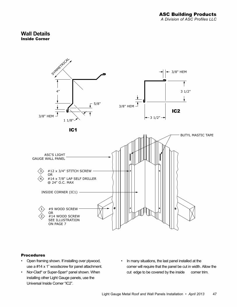
3/8" HEM
3/8" HEM
3 1/2"
3 1/2"4"
5/8"
3/8" HEM1 1/8"
SYMMET
RICA
L
BUTYL MASTIC TAPE
ASC'S LIGHTGAUGE WALL PANEL
3. #12 x 3/4" STITCH SCREWOR
4. #14 x 7/8" LAP SELF DRILLER @ 24" O.C. MAX
INSIDE CORNER (IC1)
1. #9 WOOD SCREWOR
2. #14 WOOD SCREW SEE ILLUSTRATION ON PAGE 7
IC1
Procedures• open framing shown . If installing over plywood, use a #14 x 1” woodscrew for panel attachment .• nor-Clad® or Super-Span® panel shown . When
installing other light gauge panels, use the Universal Inside Corner “IC2” .
• In many situations, the last panel installed at the corner will require that the panel be cut in width . Allow the
cut edge to be covered by the inside corner trim .
Wall DetailsInside Corner
IC2

48 April 2013 www.ascbp.com
Light Gauge Metal Roof and Wall Panels Installation Guide for Delta Rib, Delta Rib III, Nor-Clad®, Strata Rib® & 2½ Corrugated
1 1/8"
3/8" HEM
5/8"
4"
3/8" HEM
3/8" HEM
3 1/2"
3 1/2"
SYMMET
RICA
L
BUTYL MASTIC TAPE
OUTSIDE CORNER (OC1)
ASC'S LIGHTGAUGE WALL PANEL
1. #9 WOOD SCREWOR
2. #14 WOOD SCREW SEE ILLUSTRATION ON PAGE 7
3. #12 x 3/4" STITCH SCREWOR
4. #14 x 7/8" LAP SELF DRILLER @ 24" O.C. MAX
Wall DetailsOutside Corner
OC1OC2
Procedures• open framing shown . If installing over plywood, use a #14
x 1” woodscrew for panel attachment .• nor-Clad® panel shown . When installing other light
gauge panels,use the Universal outside Corner “oC2” .
• In many situations, the last panel on each side will project beyond the building corner, requiring the panel to be cut in width . Allow the cut edge to be covered by the outside corner trim .

©2008-2013 ASC Profiles LLC April 2013 Printed in the USA (BR128)
MAnUfACtURIng fACIlItIeS:
Anchorage, Alaska2441 Cinnabar Loop
Anchorage, AK 99507
McClellan, California5001 Bailey Loop
McClellan, California 95652
Salem, Oregon4063 Salem Industrial Drive NE
Salem, OR 97303800-272-7023 • 503-390-7174
Salt Lake City, Utah4228 West 1730 South
Salt Lake City, UT 84104
Spokane, Washington4111 East Ferry
Spokane, Washington 99202800-776-8771 • 509-536-4097
CoRPoRAte HeAdqUARteRS:
ASC Profiles, Inc.2110 Enterprise Boulevard
West Sacramento, CA 95691
Visit us at:www.ascbp.com