light - deakin university blogs · • refraction of light is the change in speed as light passes...
TRANSCRIPT

© Deakin University 1
Light
Introduction This topic explores the key concepts of light as they relate to: • light as an entity • vision • rectilinear (straight-line) motion of light • reflection of light • image formation in plane mirrors • refraction of light • colour of light • image formation in mirrors and lenses.
Key concepts of light The activities in this topic are designed to explore the following key concepts: • Light (radiant energy) is an entity that travels through space. • Light travels very fast—300 000 km/s in space. • Light travels in straight lines. • We see when reflected light is reflected from objects into our eyes. • Some objects are sources of light (a globe, the sun, a flame); most things we
see reflect light. • Having two eyes is necessary for judgment of depth. • Our brain puts together the stereo view we have of the world. • Our eyes and brains can be misled. • Light emitted from luminous objects keeps travelling until it is absorbed by
something. • Each point on a luminous object emits light in all directions (isotropic
emission). • Ordinary surfaces reflect/scatter light in all directions (diffuse reflection).
Mirrors reflect light at an equal angle to the incoming light (specular reflection). Many surfaces, such as polished floors, both scatter and reflect light.
• Some surfaces reflect more light than others. Black surfaces reflect the least light.

2 S C I E N C E C O N C E P T S : Y E A R S 5 – 1 0 L I G H T © Deakin University
• Light can be bent going into or out of water or glass, and this causes images of different shapes and sizes.
• Light incident perpendicularly onto a transparent surface of a material does not change direction in passing through the material.
• Refraction of light is the change in speed as light passes from one transparent material into another.
• White light consists of all the rainbow colours (spectrum) (ROYGBIV). • The colour of an object is not a property of the object. It just reflects light of
a particular colour and absorbs other colours. • The primary colours of light are red, blue and green. The secondary colours
of light are yellow, magenta and cyan. • The image in a plane mirror is inverted, and symmetrical with the object. • Our image in a plane mirror is equally far behind the mirror as we are in
front of the mirror. • Curved mirrors cause images of different sizes and shapes. • Image formation in a lens or mirror requires that:
– all the light that passes through a lens, or reflects off a mirror, contributes to the formation of an image
– the light from each point on the object that passes through the lens, or is reflected from a mirror, either converges to the corresponding point on the image (real image), or appears to diverge from the corresponding point on the image (virtual image).
Students’ alternative conceptions of light and vision Research into students’ ideas about this topic has identified the following non-scientific conceptions:
Light as an entity • The effects of light are instantaneous. Light does not travel with a finite
speed. • Light is only associated with either the source or area of illumination.
Rectilinear (straight-line) motion of light • Light is associated only with either a source or its effects. Light is not
considered to exist independently in space and hence light is not conceived of as ‘travelling’.
• Light bends around objects, like clouds. • Lines drawn outward from a light bulb represent the ‘glow’ surrounding the
bulb. • A shadow is something that exists on its own. Light pushes the shadow
away from the object to the wall or the ground and is thought of as a ‘dark’ reflection of the object.
• Light actually consists of rays.

© Deakin University S C I E N C E C O N C E P T S : Y E A R S 5 – 1 0 L I G H T 3
Vision • The only condition to see an object is if light shines on the object. Light
does not travel from the object to the eye. • Something is emitted from the eye when looking at an object. • Only the object and observer need to be bathed in light for the observer to
see the object. • The eye receives upright images. • The lens is the only part of the eye responsible for focusing light. • The lens forms an image (picture) on the retina. The brain then ‘looks’ at
this image and that is how we see. • The eye is the only organ for sight; the brain is only for thinking.
Isotropic emission of light from luminous objects • Light is not necessarily conserved. It may disappear or be intensified. • Light from a bulb only extends outward a certain distance, and then stops
(or fades away). How far it extends depends on the brightness of the bulb.
Reflection of light • Light reflects from a shiny surface in an arbitrary way. • Light is reflected from smooth mirror surfaces but not from non-shiny
surfaces. • Curved mirrors make everything distorted.
Refraction of light • Light always passes through a transparent material without changing
direction. • When an object is viewed through a transparent solid or liquid material, the
object is seen exactly where it is located.
Colour of light • A white light source, such as an incandescent or fluorescent bulb, produces
light made up of one colour. • Sunlight is different from other sources of light because it contains no
colour. • When white light passes through a prism, colour is added to the light. • The rules for mixing colour paints and crayons are the same as the rules for
mixing coloured lights. • The primary colours for mixing coloured lights are red, blue and green. • A coloured light striking an object produces a shadow behind it that is the
same colour as the light. For example, when red light strikes an object, a red shadow is formed.
• The shades of grey in a black-and-white newspaper picture are produced by using inks with different shades of grey.
• When white light passes through a coloured filter, the filter adds colour to the light.

4 S C I E N C E C O N C E P T S : Y E A R S 5 – 1 0 L I G H T © Deakin University
• The different colours appearing in coloured pictures in magazines and newspapers are produced by using different inks with all the corresponding colours.
• Colour is a property of an object, and is independent of both the illuminating light and the receiver (eye). For example, a red jumper contains red-coloured molecules.
• When a coloured light illuminates a coloured object, the colour of the light mixes with the colour of the object.
Image formation in mirrors and lenses • A mirror reverses everything. • For an observer to see the mirror image of an object, either the object must
be directly in front of the mirror, or if not directly in front, then the object must be along the observer's line of sight to the mirror. The position of the observer is not important in determining whether the mirror image can be seen.
• An observer can see more of his/her image by moving further back from the mirror.
• The way a mirror works is as follows: the image first goes from the object to the mirror surface. Then the observer either sees the image on the mirror surface or the image reflects off the mirror and goes into the observer’s eye.
• Students will often think about how a lens forms an image of a self-luminous object in the following way. They envision that a ‘potential image’ which carries information about the object leaves the self-luminous object and travels through the space to the lens. When passing through the lens, the ‘potential image’ is turned upside down and may be changed in shape.
• Blocking part of a lens surface would block the corresponding part of the image.
• With self-luminous objects, the purpose of the screen is to capture the image so it can be seen. The screen is necessary for the image to be formed. Without a screen, there is no image.
• An image can be seen on the screen regardless of where the screen is placed relative to the lens. To see a larger image on the screen, the screen should be moved further back.
• An image is always formed at the focal point of the lens. • The size of the image depends on the size (diameter) of the lens.
© Deakin University S C I E N C E C O N C E P T S : Y E A R S 5 – 1 0 L I G H T 5
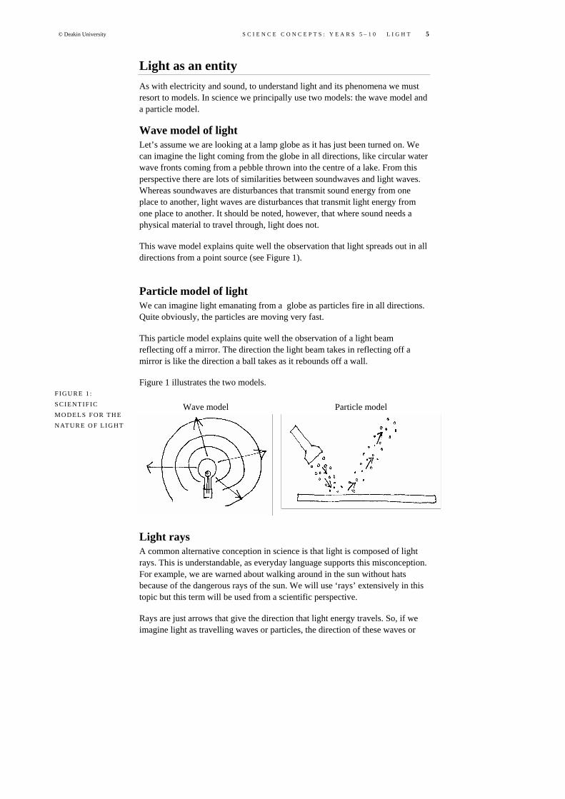
Light as an entity As with electricity and sound, to understand light and its phenomena we must resort to models. In science we principally use two models: the wave model and a particle model.
Wave model of light Let’s assume we are looking at a lamp globe as it has just been turned on. We can imagine the light coming from the globe in all directions, like circular water wave fronts coming from a pebble thrown into the centre of a lake. From this perspective there are lots of similarities between soundwaves and light waves. Whereas soundwaves are disturbances that transmit sound energy from one place to another, light waves are disturbances that transmit light energy from one place to another. It should be noted, however, that where sound needs a physical material to travel through, light does not.
This wave model explains quite well the observation that light spreads out in all directions from a point source (see Figure 1).
Particle model of light We can imagine light emanating from a globe as particles fire in all directions. Quite obviously, the particles are moving very fast.
This particle model explains quite well the observation of a light beam reflecting off a mirror. The direction the light beam takes in reflecting off a mirror is like the direction a ball takes as it rebounds off a wall.
Figure 1 illustrates the two models.
Light rays A common alternative conception in science is that light is composed of light rays. This is understandable, as everyday language supports this misconception. For example, we are warned about walking around in the sun without hats because of the dangerous rays of the sun. We will use ‘rays’ extensively in this topic but this term will be used from a scientific perspective.
Rays are just arrows that give the direction that light energy travels. So, if we imagine light as travelling waves or particles, the direction of these waves or
F IGU R E 1 : S C IE NT IF IC MO DE LS F OR TH E NATU R E O F L IG HT
Wave model Particle model

6 S C I E N C E C O N C E P T S : Y E A R S 5 – 1 0 L I G H T © Deakin University
particles is provided by rays. Quite often in diagrams showing luminous objects, waves or particles are not shown, just the rays. Figure 2 shows how rays relate to the direction of waves or particles. A diagram that explains light phenomena by the drawing of rays is called a ‘ray diagram’.
Many of the diagrams that we draw to show and explain optical phenomena are called ‘ray diagrams’. It is important to remember that in interpreting these diagrams the ray just gives the direction the light takes. For example, the ray diagram in Figure 3 shows how light reflects off a plane mirror.
Vision Understanding the process by which we see objects is very important to developing an understanding of the many of the properties of light. From a scientific perspective, to be able to see an object, light must reflect off the object and enter your eye(s). The necessary requirement for vision is that light must enter the eye. The light that enters your eye activates vision cells, which in turn create an electrical impulse that is sent to the brain via nerves. The ray diagram in Figure 4 shows how a person sees a tree.
F I GUR E 2 : RAYS AND MO DE LS F O R T H E N AT U R E
OF L IG HT
Waves and rays Particles and rays Rays
F I GUR E 3 : REF LE C TI ON OF L IG HT FRO M A P LANE
MIR R OR
FI GUR E 4 :
VIS IO N OF A T R EE

© Deakin University S C I E N C E C O N C E P T S : Y E A R S 5 – 1 0 L I G H T 7
A common alternative conception is that light only needs to illuminate an object for it to be seen. Another alternative conception is that apart from light being incident on the object, ‘visual rays’ must also be emitted from the eyes. These two alternative conceptions are illustrated in the ray diagrams shown in Figure 5.
This activity involves several steps. Firstly, the students complete a questionnaire (shown below), with several questions relating to different aspects of light. They should do this without conferring with other students.
The students then cut up their questionnaires to separate their responses to each question, and place their responses in separate piles at the front. Once this is done there will be separate piles of Question 1 answers, Question 2 answers, and so on.
The class is then divided into five research groups (depending on how many questions were originally given on the questionnaire). Each research group analyses a pile of questions.
Each group reports their findings back to the rest of the class. They may even suggest an experiment to resolve differences of opinion.
A number of activities can arise out of the discussion of ideas, such as: • a trip to a photographic darkroom • a student experiment: can you feel a stare? • an activity relating vision to the other senses.
FI GUR E 5 : ALTE RN ATI VE CON C EP TI ONS OF VI SI ON
AC T IV IT Y: POS T-B OX

8 S C I E N C E C O N C E P T S : Y E A R S 5 – 1 0 L I G H T © Deakin University
Question 1 For the two situations shown below: a) draw arrows to show how light from the sun helps the person to see the tree b) draw arrows to show how the light from the bulb helps the person see the
bulb.
Complete the following sentence. My idea of seeing can be written as: ‘to be able to
see an object …’ _______________________________________________________
______________________________________________________________________
______________________________________________________________________
______________________________________________________________________
If you were placed in a room where there was no light, would you be able to see? If
you were to spend some time in this room, would you be able to see then?
______________________________________________________________________
______________________________________________________________________
______________________________________________________________________
Would a cat or owl be able to see in a room where there was no light? Why do you
think this? ____________________________________________________________
______________________________________________________________________
______________________________________________________________________
Question 3 If you were directly behind someone, would you be able to attract their attention
by just staring at them? Why? ____________________________________________
______________________________________________________________________
______________________________________________________________________
______________________________________________________________________

© Deakin University S C I E N C E C O N C E P T S : Y E A R S 5 – 1 0 L I G H T 9
Question 4 Which of the following objects make light? (Circle those that do.) – glowing coals of a fire at night – glowing coals of a fire during the day – the Moon – a mirror – a bar heater operating at night – a bar heater operating during the day – a TV operating at night – a TV operating during the day – glow-in-the-dark stickers at night – glow-in-the-dark stickers during the day.
Does daylight affect the amount of light an object gives out? Explain your answer.
______________________________________________________________________
______________________________________________________________________
______________________________________________________________________
Question 5 A person is standing outside, shining a torch parallel to the ground. ____________
___________________________________________________________________
___________________________________________________________________
___________________________________________________________________
– If it is night-time, how far will the light travel from the torch? ______________
___________________________________________________________________
___________________________________________________________________
___________________________________________________________________
– If it is daytime, how far will the light travel from the torch? ________________
___________________________________________________________________
___________________________________________________________________
___________________________________________________________________
– Does the daylight affect how far light travels from an object? Explain your
answer. ____________________________________________________________
___________________________________________________________________
___________________________________________________________________
___________________________________________________________________

10 S C I E N C E C O N C E P T S : Y E A R S 5 – 1 0 L I G H T © Deakin University
This activity may be required if students believe they can see in the complete absence of light. It involves experiencing complete darkness, which many students may not have done. The darkroom needs to be checked to ensure that no light can enter the room. • Pair up students and get them to observe how their partner’s pupils dilate
when the light goes off, and then contract quickly when the light goes on. This could lead to a discussion on how the pupils open and close depending on the light conditions. You could extend this discussion to how well nocturnal animals can do this.
• In the darkroom with no light, shine a small torch onto a white sheet of paper and then a black sheet. Students should see quite easily that the room lights up much more with reflection off the white paper. Try a reflection off a mirror to further contrast the effects.
There will be some students who believe that they can gain another person’s attention through just staring at them. There is a belief that something emanates from the eye in the vision process. This can be tested through an experiment generated by the students. As a follow-up activity, the students could determine the extent of their peripheral vision. They should notice that they have a wide field of vision.
These activities should lead students to think nothing emanates from the eye during staring.
Many students believe that light does not need to enter the eye for vision of objects to occur. Many also believe that light only needs to illuminate an object for vision of that object to occur. In discussions with the students, give an analogy with the senses: • For the sense of touch to work, something must touch your skin. If it does,
there are sense receptors that will be activated that send a message to your brain. You can’t feel anything unless the receptors are activated.
• For smell, something must go up the nose and activate small receptors. Again the message gets sent to the brain.
• For taste, something must be placed on the tongue. Similarly, something must enter the ear for you to be able to hear.
• In all these senses, something must activate a sense receptor before a message is sent to the brain. It then seems plausible that this is how sight works. Light enters the eye, activates sense receptors at the back of the eye and messages get sent to the brain.
The discussions should lead students to believe that light must enter the eye for vision of an object to be possible. They should draw ray diagrams to show the scientific view.
Explanatory note: From a scientific view, we cannot feel a stare. Many people believe they can; they give the argument that some people have ESP (extra sensory perception) or a sixth sense. However, from a scientific perspective, ESP is not possible. Certainly, the act of staring does not result in anything emanating from the eyes.
No person, nor any animal, can see in the total absence of light. The perception of vision occurs when light enters the eye; no light means no vision is possible.
AC T IV IT Y: TRI P TO A PHO TO GR A PH IC
DAR KRO OM
AC T IV IT Y: STU DE NT EXP ER IME NT: C AN Y OU FEEL A STA R E?
AC T IV IT Y: R EL AT IN G VIS IO N TO T HE
OTH ER S ENSE S

© Deakin University S C I E N C E C O N C E P T S : Y E A R S 5 – 1 0 L I G H T 11
After spending some time in the dark, our pupils dilate to allow more light to enter the eye—this is why we can see better after spending some time in dark (but not totally dark) conditions. Animals such as cats and owls have the ability to dilate their eyes very well.
Rectilinear (straight-line) motion of light From a scientific view, light travels in straight lines like very fast bullets (imagining a particle model). Also, light will keep travelling indefinitely until it hits something. This concept is difficult for many people to grasp. For example, many people believe the alternative conceptions that light from a glow-in-the-dark sticker only stays on or just around the sticker, and that light from a small candle only goes a few metres. These misconceptions derive from a view that light from a luminous object only travels as far as it obviously can illuminate some other object. However, if we are to believe the scientific vision concept, then it must follow that the ability to observe any luminous object in the dark means that light from the luminous object is at least reaching the eye. If you can see the sticker or candle flame, then does not light from these objects at least reach your eyes? If you can see the sticker or candle flame through a telescope a few kilometres away, does this not mean that light is still at least reaching your eyes?
For most luminous objects on Earth, the light they emit gets absorbed by objects after some distance of travel. However, once light reaches space—and we know that it does (from pictures taken from the space shuttle)—then light will keep travelling until it hits something; this could be some distance. For example, light from distant stars that we see in the night sky may be many billions of light years away. A light year is defined as the distance light will travel in a year. When you consider that light travels 300 000 kilometres every second, then a light year is a very, very long distance.
Many students believe that some objects emit light when in fact they only reflect it (e.g. the Moon). They also believe that light doesn’t travel very far from dim sources of light (e.g. glow-in-the-dark stickers). There is also a belief that light from luminous objects travels further at night than during the day. This activity involves the following: • A series of cards (examples of two cards are shown in the figure Examples of
cards) are placed around the room. Each card depicts a luminous object and a person looking at the luminous object.
• Each student is given a survey (shown below) to compete after looking at the cards around the room. The students move around the room and fill in their survey for each card.
• A discussion of the students’ survey results follows. If the students believe that light needs to enter the eye to see an object, then if they can see the object then light is at least reaching them.
• The discussion should end with the view that light from luminous object keeps travelling until it gets absorbed. Daylight conditions do not affect how light travels from luminous objects.
AC T IV IT Y: WHAT G IV ES
OFF LI GHT?
12 S C I E N C E C O N C E P T S : Y E A R S 5 – 1 0 L I G H T © Deakin University
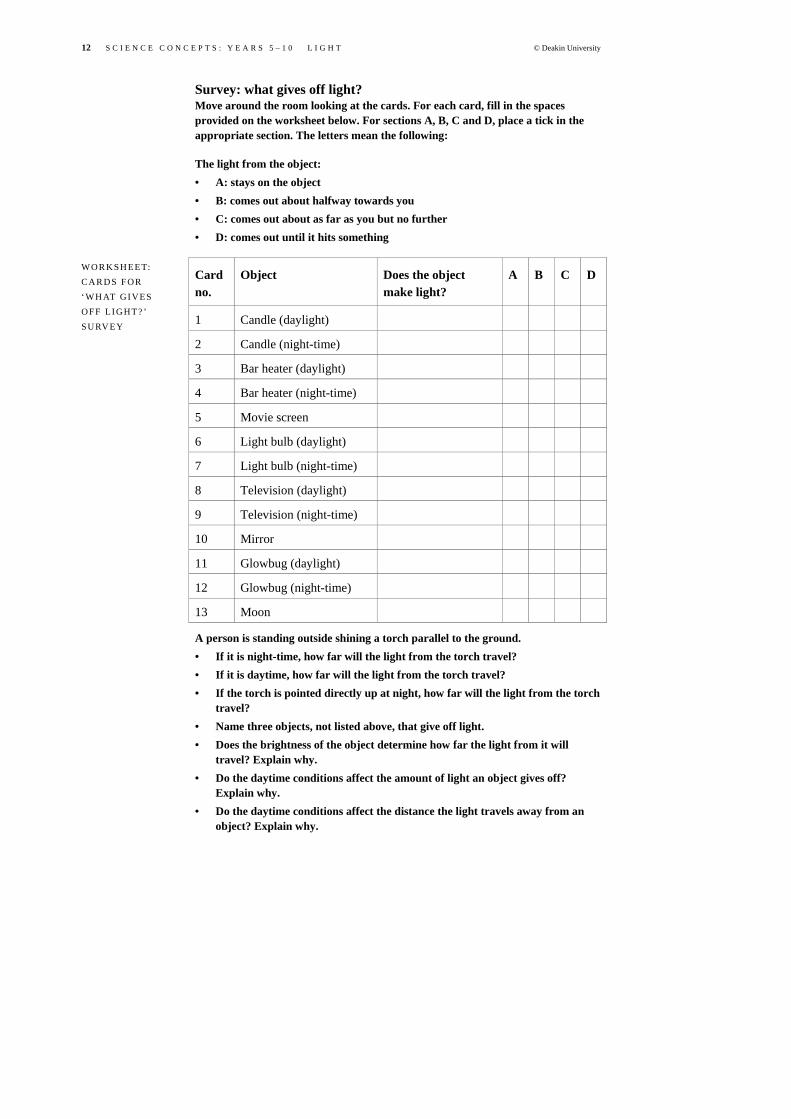
Survey: what gives off light? Move around the room looking at the cards. For each card, fill in the spaces provided on the worksheet below. For sections A, B, C and D, place a tick in the appropriate section. The letters mean the following:
The light from the object: • A: stays on the object • B: comes out about halfway towards you • C: comes out about as far as you but no further • D: comes out until it hits something
Card no.
Object Does the object make light?
A B C D
1 Candle (daylight)
2 Candle (night-time)
3 Bar heater (daylight)
4 Bar heater (night-time)
5 Movie screen
6 Light bulb (daylight)
7 Light bulb (night-time)
8 Television (daylight)
9 Television (night-time)
10 Mirror
11 Glowbug (daylight)
12 Glowbug (night-time)
13 Moon
A person is standing outside shining a torch parallel to the ground. • If it is night-time, how far will the light from the torch travel? • If it is daytime, how far will the light from the torch travel? • If the torch is pointed directly up at night, how far will the light from the torch
travel? • Name three objects, not listed above, that give off light. • Does the brightness of the object determine how far the light from it will
travel? Explain why. • Do the daytime conditions affect the amount of light an object gives off?
Explain why. • Do the daytime conditions affect the distance the light travels away from an
object? Explain why.
WOR KSH EE T: C A R DS F OR ‘WH AT GI VES OFF LI GHT? ’ SURV EY

© Deakin University S C I E N C E C O N C E P T S : Y E A R S 5 – 1 0 L I G H T 13
You will need: • two candles • a study lamp (containing a fluorescent light tube) • a screen • some obstacles that will create a shadow on a screen.
With the two arrangements shown in the figure Shadow shapes (1), predict the size and shape of the shadow/illuminated shape that you will see on the screen for both cases before lighting the candle.
If the hole was placed higher, what would you expect?
What happens to the shape of the shadow/illuminated shape when the obstacle/circular aperture is moved closer to/further from the candle?
FI GUR E: EXA MPL E O F C A R DS
AC T IV IT Y: SHA DOW SHA PE S

14 S C I E N C E C O N C E P T S : Y E A R S 5 – 1 0 L I G H T © Deakin University
Predict what you will observe on the screen for each of the arrangements in the figure Shadow shapes (2).
Each of your observations can be explained by use of a ray diagram. This is usually an overhead shot of the arrangement with rays drawn from the luminous source to show the direction of light travel. One of the observations is explained by the ray diagram in the figure Shadow shape.
The students should first predict the effects of the following arrangements, then after they have made their observations they should draw ray diagrams to explain these effects: • A small light source in front of an obstacle and screen. • Two small light sources in front of an obstacle and a screen. • A fluorescent light source in front of an obstacle and a screen. This should
achieve a shape that has a partial and a full shadow. • A bulb with an easily seen filament in front of a card with just a pinhole in
front of a screen. You should see an image of the filament on the screen (called a ‘pinhole image’).
The students should gain the view that from each point on a luminous object, light travels in all directions. This view explains pinhole images as well as partial shadow shapes.
FI GUR E: SHA DOW S HA P E S ( 1 )
F I GUR E: SHA DOW
S HA P E S ( 2 )
F I GUR E: SHA DOW
SHA PE

© Deakin University S C I E N C E C O N C E P T S : Y E A R S 5 – 1 0 L I G H T 15
Partial and full shadow shapes Shadow shapes can be predicted using the concepts that ‘light travels in straight lines’ and ‘each point on the luminous object emits light in all directions’. The ray diagrams in Figure 6 show what would be expected when a small light globe, and then a larger light globe, is placed in front of an obstacle and a screen.
For the small light source, you obtain a sharp shadow on the screen. No light from the globe reaches the shadow region. However, for the larger light source there will be regions of full shadow, where not light reaches, and other regions of partial shadow, where some light reaches. The region of full shadow is called the ‘umbra’ and the region of partial shadow is called the ‘penumbra’. This is illustrated in Figure 6.
Large light source
Small light source
Pinhole cameras The first cameras were very simple structures. They consisted of an enclosed box that contained a small hole (pinhole) at one end and a photographic plate at the other end. By pointing the pinhole at an object, a faint image would appear on the plate. Because of the faint image produced, exposure times were quite lengthy.
F I GUR E 6 : PART IA L AND FUL L S H A D O W S

16 S C I E N C E C O N C E P T S : Y E A R S 5 – 1 0 L I G H T © Deakin University
You will need: • a cylindrical container opened at one end • waxed paper • a rubber band • matches or a lighter • a candle.
Puncture a very small hole (pinhole) in the end of the cylinder. Cover the open end with waxed paper and secure it with a rubber band. Place the candle in front of the pinhole and light the candle. Darken the room. While one student moves the pinhole end back and forth, have another watch the waxed-papered end and describe the image that is produced. Have the students draw a ray diagram to explain how the image is produced.
Make the hole slightly larger. Ask the students what they notice about the image. Enlarge the hole to be about 1 cm in diameter. What do they notice then? Can they explain their observation?
The clearest image is formed with the smallest pinhole. However, the smaller the aperture, the less light passes through it to form the image. Therefore, the image will be quite dim. As the aperture becomes larger, the image becomes brighter but more blurred.
Reflection of light When light hits mirrored and non-mirrored surfaces, most often it will be reflected off the surface. There is a belief by many students that light that falls on non-luminous objects stays on the object. However, a scientific view of vision implies that light must reflect off non-luminous objects, otherwise they would not be able to be seen.
Light reflects in an orderly way from mirrored surfaces, but for non-mirrored surfaces the reflection will be disorderly. For light reflecting off a mirrored surface, imagine a ball bouncing off a smooth surface. The ball bounces off in the one direction. For light reflecting off a non-mirrored surface, imagine a ball bouncing off a very rough surface. In this circumstance, a ball will not always bounce off in a particular direction. So, for a beam of light hitting a flat mirror, the beam will reflect in the one direction (as in the model the ball bounces off in
AC T IV IT Y: MAK IN G A P I NHO LE
C A M E R A
F I GUR E: P I NHO LE C A M E R A

© Deakin University S C I E N C E C O N C E P T S : Y E A R S 5 – 1 0 L I G H T 17
the one direction), whereas for a beam of light hitting a non-mirrored surface, the beam spreads out reflecting in all directions (as in the model the ball may bounce in many different directions).
Light reflecting off surfaces in an orderly way is called ‘specular reflection’ and light reflecting off surfaces in a disorderly way is called ‘diffuse reflection’. Figure 7 illustrates both types of reflection.
You will need: • a light box • an A3 sheet of white paper • a collection of plane and curved mirrors.
The light box is constructed so that it can emit single or multiple thin beams of light. By placing white paper under the light box, the thin beams of light can be seen clearly. Alternatively, you can use a torch, white paper and a comb as shown in the figure Reflection of light demonstration.
Investigate how light reflects off plane (flat) mirrors and various curved mirrors. Can you come up with a rule that would allow you to predict how a light beam would reflect off a plane mirror? Can you come up with a rule for reflection of light from curved mirrors?
Complete the ray diagram in the figure Ray diagram to complete, to show the path light will take upon reflection off the series of plane and curved mirrors (the reflected ray should reach the bottom right-hand side of the box).
F I G U R E 1 2 : REF LE C TI ON OF
LI GHT
Specular reflection Diffuse reflection
AC T IV IT Y: IS TH ERE A R U L E F O R
REF LE C TI ON?
F I GUR E: REF LE C TI ON OF L IG HT DEM ONS TR A-
TI ON

18 S C I E N C E C O N C E P T S : Y E A R S 5 – 1 0 L I G H T © Deakin University
Many students have a good intuitive sense of how light reflects off mirrors, but at the same time they do not believe that light reflects off curved mirrors in a similar fashion to how it reflects off plane mirrors. Many students also believe that when light hits objects it does not reflect, it just stays on the object. For example, when light hits white paper, it just stays on the paper. Some activities with reflection are listed here. • Use a laser (laser pointers are quite common). Have a mirror set up in the
front of the room and stand with the laser at the back. Get students to get into positions that they predict will be zapped by the laser on reflection from the mirror. Try it also with a curved mirror. Also with two mirrors perpendicular to each other (the laser light should reflect back the same way it came, like reflectors do on roads and bicycles). With chalk dust, or an atomiser, students will be able see the path of the laser light.
• With a laser set up in the one direction, have a number of students with mirrors in front of the laser. Get the students to move their mirrors so that after four or five reflections the laser light will hit a certain target.
• Light ray boxes provide narrow beams that can be placed in front of plane and curved mirrors. Get the students to generate their own rule of reflection based on their observations using the light ray boxes.
• As an argument to support the view that light reflects in all directions from non-mirrored surfaces, have a number of students stand in front of a white sheet of paper that you have illuminated with a torch beam. If all the students can see the illuminated circle, then light is reaching their eyes. If many students can see the circle, then light must be reflecting in all directions.
• Give the students ray diagrams to complete. Get them to predict the path of light through a series of mirrors (like that shown in the figure below).
The ray that is drawn should reflect off each mirror.
At the end of the activity, students should have a view of specular reflection from mirrored surfaces using a rule for reflection (this rule should be used for plane and curved mirrors). They should also have a view of diffuse reflection where light reflects in all directions from non-mirrored surfaces.
AC T IV IT Y: REF LE C TI ON OF L IG HT
F I GUR E: RAY DI AG RAM TO COM PL ETE

© Deakin University S C I E N C E C O N C E P T S : Y E A R S 5 – 1 0 L I G H T 19
Image formation in plane mirrors To understand how the image is formed in a plane or curved mirror, you need to understand the following concepts: • Light needs to enter the eye after reflection off an object for vision of that
object to be possible. • Light reflects off non-mirrored surfaces in all directions. • Light reflects off mirrored surfaces in a regular way so that the angle the
incident light makes with the mirror surface equals the angle the reflected light makes with the mirror surface. This is called the ‘reflection rule’.
Images in a plane mirror When you look into a plane mirror, do you see your face or do you see an image of your face? Everyday language would suggest that you would see your face, but from a scientific perspective you are seeing an image of your face. We need to make the distinction between an object and its plane mirror image because while they are the same size and shape, they are in different locations. Figure 8 illustrates this point.
In Figure 8 there are two observers, represented by eyes, where one observer is looking at the top of a flower and the other observer is looking at an image of the top of the flower. Light from a luminous source, presumably the sun, reflects off the top of the flower in all directions. Some of this light goes directly into one observer’s eyes. Some of the light also gets reflected off the mirror and enters the eyes of the other observer. The observer who sees the flower will get the perception that light is diverging from one particular point in space (the location of the flower), whereas the observer who sees the image will get the perception that light is diverging from another point in space (the location of the image). The significance of the eye in image formation is important as the image is created when the light enters the observer’s eye.
When directly observing an object, light from the object travels in a straight path to the eye. However, if the light from the object is redirected by reflection off a mirror (plane or curved), or after passing through a transparent material, then an image will be formed as the observer will perceive its location to be different to that of the actual object. If the redirected light only appears to come
F I G U R E 8 : IMA GE IN A PL AN E
MIR R OR

20 S C I E N C E C O N C E P T S : Y E A R S 5 – 1 0 L I G H T © Deakin University
from points in space, then the image formed is called a ‘virtual image’. In the case of the plane mirror, the reflected light appears to come from an image located behind the mirror, light doesn’t originate from behind the mirror. The distance from the image to the mirror is equal to the distance from the object to the mirror, and the line between the object and image cuts the mirror axis at right angles. This is illustrated in Figure 9.
In the ray diagram in Figure 9, the observer on the left will not see an image of object B but will be able to see an image of object A. Can you explain why? Hint: the light from the object must reflect off the mirror according to the reflection rule and enter the eye of the observer before an image can be seen.
You will need: • two candles of similar length • matches or a lighter • a large perspex sheet, mounted vertically.
Place the two candles on either side of the perspex sheet as in the figure below.
In a darkened room, light one of the candles and have the students look at the sheet of perspex. They should see not only an image of the lit candle but also the unlit candle on the other side. Have a student move the unlit candle until it is at the same position as the image; when this occurs it will appear that there are two lit candles. Have the student touch the top of the unlit candle; it will appear that they are burning their hand.
How does the position of the unlit candle relate to the position of the lit candle? Now place the lit candle to one side of the perspex sheet. Is there still an image? If so, place the unlit candle in its position. What do you notice?
F I G U R E 9 : THE PO SIT I ON OF THE VIRTU AL IMA GE IN A PLA NE M IR RO R
AC T IV IT Y: WHE R E I S THE IMA GE IN A PLA NE
MIR R OR?
F I GUR E: WHE R E I S THE IMA GE IN A PLA NE
MIR R OR?

© Deakin University S C I E N C E C O N C E P T S : Y E A R S 5 – 1 0 L I G H T 21
This demonstration should convince you and your students that the image of the candle is indeed behind the perspex. If you place the unlit candle in any position other than the image position, you will observe two candles in the perspex.
This demonstration can form part of a predict–observe–explain (POE) strategy. Students should fill in the following prediction and observation worksheet as you undertake each of the demonstrations listed.
Question 1 From interviews with secondary school students like you, the following ideas arose about where the image of a rod appears to be in a plane mirror. Circle the situation you think is correct. Note that part (vi) is left blank—use this if you do not agree with any of the other situations.
On each of the diagrams, draw a ray diagram to explain how the light from the object gets reflected off the mirror and into the person's eye for them to be able to see the image.
The class demonstration suits idea: _______________________________________
Class idea about the position of the image in a plane mirror:___________________
Question 2 If the person in the diagram below were to shift position from the right to the left, circle your choice of the correct statement: • the image would move to the left • the image would move to the right • the image would not move.
WOR KSH EE T: WHE R E D OE S THE IM AGE APP EA R TO BE IN A PL AN E MIR R OR?

22 S C I E N C E C O N C E P T S : Y E A R S 5 – 1 0 L I G H T © Deakin University
The class demonstration suits idea: ___________________________________
Class idea about the position of the image in a plane mirror:______________
Question 3 The mirror is changed in position to the left, as in the diagram below. Two people are looking into the mirror. Circle your choice of the correct statement:
The person on the right: a) can see the image b) cannot see the image.
The person on the left: a) can see the image b) cannot see the image.
The class demonstration suits idea: ________________________________________
Class idea about the position of the image in a plane mirror:___________________
Question 4 How much of an image can be seen in a mirror of a given size? In the diagram below, a person is looking into a mirror and sees an image of himself. • How much of their body are they able to see as an image in the mirror? • Apart from changing the size of the mirror, what could the person do to see
more of themself? • If the person moved away from the mirror:
i) What happens to the size of the image? ii) What happens to the position of the image? iii) Draw ray diagrams in the diagrams below to support your views.
How long does a mirror have to be for you to be able to see a full-length image of yourself? Use the space below to draw ray diagrams to determine the length. Remember: all light that reflects off the mirror obeys the rule of reflection.

© Deakin University S C I E N C E C O N C E P T S : Y E A R S 5 – 1 0 L I G H T 23
Explanatory note: The two reading tests in the figure Reading tests confirm the concept that the image is behind the mirror. One test is a mirror image of the other. In this activity, a student stands before a mirror, upon which a reading test is placed (upright). The student moves back until they can just read a particular line on the test. Then, the reading test on the mirror is removed and the student holds another test, facing the mirror but with the test resting on their chest. Once again the student is asked to read the same line as before; only this time the student will not be able to because the reading test image is twice the distance away.
(Lapp 1993, p. 60)
Other activities include: • Have two mirrors set up at right angles to each other. Students will see three
images of an object placed in front of the mirrors. • Have two mirrors placed parallel so that the object is in between the mirrors.
An infinite number of images can be seen. • Have students use cardboard, tape, glue and two small mirrors to construct a
periscope.
FI GUR E: REA DI NG TEST S

24 S C I E N C E C O N C E P T S : Y E A R S 5 – 1 0 L I G H T © Deakin University
After completing these activities it is important for the students to explain their observations in terms of the reflection of light, in ray diagrams.
You will need: • two plane mirrors • a small object.
Arrange two upright mirrors to be: • at right angles • at an angle, forming a ‘V’ • parallel.
How many images are formed of a pencil placed upright in front of the mirrors? Does the angle in the V affect the number of images? Can you explain the appearance of multiple images through use of a ray diagram? (Hint: each time the light gets redirected through reflection it appears to come from a different location. This in itself is an image, and so if the light undergoes multiple reflections there can be multiple images formed.)
Look into the upright mirrors that are at right angles and observe the image that is centred over the mirror join. Wink your left eye. What do you notice? Why?
Explanatory note: When light from an object reflects once off a plane mirror, the redirected light appears to come from an image located behind the mirror. If light is reflected more than once (as in the case of multiple mirrors), each time the light gets redirected it appears to come from a new image. So, with more than one mirror, multiple images are formed. If the mirrors are parallel to each other the light can reflect back and forwards indefinitely and so an infinite number of images are created.
You will need: • a mirror as large as the size of your head • masking tape.
Set up the mirror in front of you.
How big does a mirror need to be for you to see an image of all of yourself? How much of a mirror is needed to see an image of all of your face?
Use two pieces of tape stuck across a hand mirror to mark the portion of the mirror needed to see from the top of an image of your head to your chin. How does the distance between the tapes compare with the length of your head from top to chin?
AC T IV IT Y: MULT IP LE
IMA GE S
F I GUR E: MULT IP LE IMA GE S
AC T IV IT Y: H O W B I G D OE S A MIR R OR
NEE D TO BE?

© Deakin University S C I E N C E C O N C E P T S : Y E A R S 5 – 1 0 L I G H T 25
Perhaps you could try this with a full-length mirror, to see which part of the mirror is needed to see from the top of an image of your head to the tip of an image of your toes. Would you expect the same result?
Can you draw a ray diagram to explain your observation?
Explanatory note: The observation that you only require a mirror half your size to see an entire image of yourself is quite surprising for most people. However, if you apply the principles of light reflection and the idea that light needs to enter the eye to see something then this observation can be explained.
Some famous illusions performed by magicians depend on the use of mirrors. In one illusion a man sitting at a table gradually disappears, to be replaced by his skeleton! You can make your own version of this illusion by placing a plate of glass diagonally across a box painted black. The two dolls (one dressed as a skeleton) are lit by two separate, shaded lights.
Why is a plate of glass used, rather than a mirror? The position of the dolls is important. Where must they be? Each light must illuminate only one doll, and not the other. Why? Why is the interior of the box painted black?
FI GUR E: IMA GE OF A PER SON IN A
PLA NE MIR RO R
AC T IV IT Y: MAG ICI AN 'S
IL LUS IO N
F I GUR E: MAG ICI AN ’S
IL LUS IO N
26 S C I E N C E C O N C E P T S : Y E A R S 5 – 1 0 L I G H T © Deakin University
Refraction of light Refraction of light is a phenomenon associated with light passing from one transparent medium into another. For example, refraction occurs when light passes from air into water. Quite often the light changes direction when passing from one transparent medium into another. Similarly to images in plane and curved mirrors, as light gets redirected an image is formed. Explore bending light effects in the activities described in this section.
The effects in each of the activities can be explained by the redirection of light that comes from the object we are looking at. The redirected light appears to come from points in space other than the position of the object, and so we see images of the object. Whereas in plane mirrors we observe exact copies of the object, in the activities we observe distorted copies of the object. The underlying reason for the effects is that light has changed direction in passing through transparent materials. The phenomenon where light passes through transparent materials is called ‘refraction’.
The reason light changes direction in passing from one transparent material into another is that it changes speed. Light is fastest in space and slows slightly when it enters our atmosphere. There is also a significant drop in speed when light enters water. Light is slowest in diamonds (it is responsible for diamonds’ sparkling characteristic).
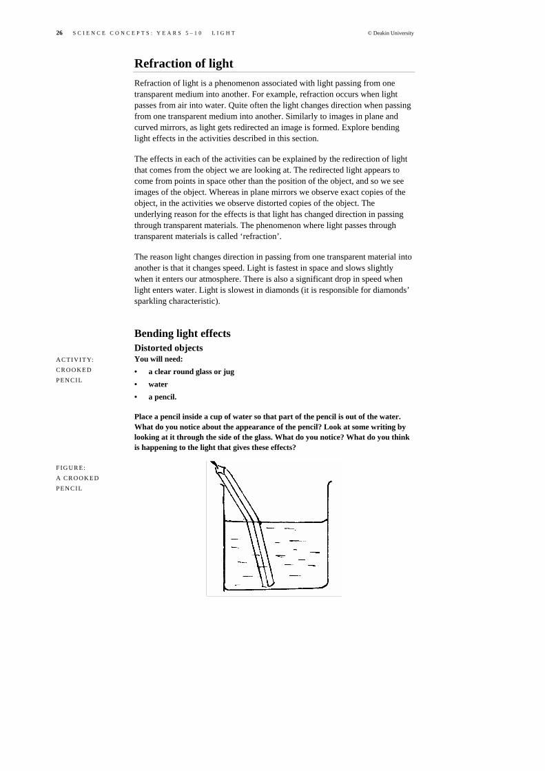
Bending light effects Distorted objects You will need: • a clear round glass or jug • water • a pencil.
Place a pencil inside a cup of water so that part of the pencil is out of the water. What do you notice about the appearance of the pencil? Look at some writing by looking at it through the side of the glass. What do you notice? What do you think is happening to the light that gives these effects?
AC T IV IT Y: C R O O K E D
PEN C IL
F IG UR E: A CR OOK ED PEN C IL

© Deakin University S C I E N C E C O N C E P T S : Y E A R S 5 – 1 0 L I G H T 27
You will need: • water • a drinking glass • a small coin.
Place a small coin on a sheet of paper and on top of it place a glass full of water. The coin cannot be seen, looking through the sides of the glass! The coin can still be seen through the top surface of the water, but you might like to place a disc or saucer on top to stop it being seen.
You will need: • water • an opaque cup (china or plastic) • a small coin.
Place a small coin at the bottom of a cup and move your eye down so that the coin is just hidden by the rim of the cup. Keeping your head steady, pour water into the cup. The coin comes into view!
You will need: • a biological specimen encased in perspex or glass.
A block of perspex or glass is a wonderful thing and can produce a number of strange effects if you look through it from different directions. Sides act as mirrors, if you look through at an angle. Objects appear in strange places.
AC T IV IT Y: THE DIS AP PE AR ING
C O I N
F I GUR E: THE DIS AP PE AR ING C O I N
AC T IV IT Y: THE APP EA R IN G
C O I N
F I GUR E: THE APP EA R IN G
C O I N
AC T IV IT Y: AN E NCASE D IMA GE

28 S C I E N C E C O N C E P T S : Y E A R S 5 – 1 0 L I G H T © Deakin University
Ask a friend to hold it up in front of their eye. It will appear to float out from their face! Look at and through the block. How many different observations can you make?
A biological specimen encased in perspex or glass can be seen a number of times. The specimen seems to be closer to the surfaces than it really is, and its position seems to shift as you move the block around. The same thing can be noticed if you look at fish in a tank.
A model for refraction The following activity builds up a series of observations related to the path of the light through transparent materials.
You will need: • a light box (this produces a thin beam of light) • various shaped transparent objects.
Explore what occurs with the path of the light that is incident on different shaped transparent materials. Some effects that you might find are shown in the figure below. Try different types of transparent materials.
Explanatory note: Some of the effects of light passing through transparent materials are: • When light hits a transparent surface, some of the light reflects and some
passes into the transparent material. • Where light hits the surface at an angle less then 90˚, it will change
direction. There is more bending of light at smaller angles to the surface than at greater angles.
• Where light hits the surface at an angle of 90˚ to the surface, it will not change direction.
AC T IV IT Y: TRA NSPARENT MAT ER IAL S AND TH E PATH OF L IG HT
FI GUR E: THE PAT H O F LI GHT THR OUG H TRA NSPARENT
MAT ER IAL S

© Deakin University S C I E N C E C O N C E P T S : Y E A R S 5 – 1 0 L I G H T 29
• Where light leaves a transparent material at an angle less than 90˚, it will change direction.
• For some angles to the surface, light inside a transparent material reflects off the surface rather than passing through the surface.
• The degree of change in direction is more pronounced in some transparent materials than others.
These effects, shown in Figure 10, can be attributed to the view that light changes speed in passing from one transparent material into another. Therefore, from a scientific view, the refraction of light is the change in speed when light is passed from one transparent material into another. Many textbooks give a view that refraction is the bending of light, but this is not true, as light does not always bend in passing through a transparent material.
Light from air into water
Light from air into glass
Light from air into diamond
Light hitting the surface of water
Small angles to the surface Large angles to the surface
Light passing through a glass block
Light passing through lenses
Convex lens Concave lens
F I G U R E 2 6 : REF R AC TI ON
EFF EC TS

30 S C I E N C E C O N C E P T S : Y E A R S 5 – 1 0 L I G H T © Deakin University
To understand the refraction effects, various teaching models can be used. One model uses a marching model. You will require an area outside that is sandy (e.g. a long-jump pit). The sand area represents glass and the grassed area surrounding the sand area represents air. Three students locked together represent the front of a beam of light. Figure 11 illustrates the analogy.
The students (locked together) walk towards the sand at an angle to the sand boundary. As soon as a student reaches the sand they are to take smaller paces (slow down). As one side of the student group reaches the sand first and slows down this has the effect of changing the direction of the whole group. The path of the student group will bend as the boundary of the sand/grassed area. This path is like that for light entering glass.
If the group walks in a direction perpendicular to the sand then there will be no change in direction. This is also consistent with what happens with light entering transparent materials.
This model successfully explains: • Light entering glass at an angle less than 90˚ to the glass will change
direction in a specific way. • Light entering glass at 90˚ to the glass surface will not change direction. • Light passing from glass into air at an angle less than 90˚ to the glass will
change direction in a specific way. • Different transparent material can be modelled with different grades of
sand, from very soft sand where it is hard to walk through to less soft sand.
This model does not explain: • Light partially reflects at the boundary between two transparent materials. • With light passing from glass into air at an angle less than 90˚ to the glass,
it is possible that at some angle the light reflects totally. This phenomenon is known as ‘total internal reflection’.
F I G U R E 2 7 : MAR C HI NG MOD EL F OR REF R AC TI ON
Light entering glass from air Marchers walking from grass onto sand
F I G U R E 1 2 : MAR C HI NG MOD EL F OR
REF R AC TI ON
© Deakin University S C I E N C E C O N C E P T S : Y E A R S 5 – 1 0 L I G H T 31
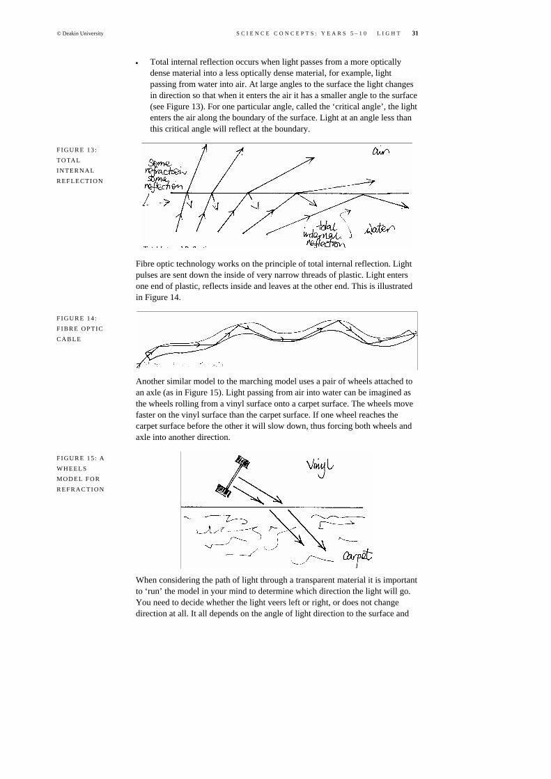
• Total internal reflection occurs when light passes from a more optically dense material into a less optically dense material, for example, light passing from water into air. At large angles to the surface the light changes in direction so that when it enters the air it has a smaller angle to the surface (see Figure 13). For one particular angle, called the ‘critical angle’, the light enters the air along the boundary of the surface. Light at an angle less than this critical angle will reflect at the boundary.
Fibre optic technology works on the principle of total internal reflection. Light pulses are sent down the inside of very narrow threads of plastic. Light enters one end of plastic, reflects inside and leaves at the other end. This is illustrated in Figure 14.
Another similar model to the marching model uses a pair of wheels attached to an axle (as in Figure 15). Light passing from air into water can be imagined as the wheels rolling from a vinyl surface onto a carpet surface. The wheels move faster on the vinyl surface than the carpet surface. If one wheel reaches the carpet surface before the other it will slow down, thus forcing both wheels and axle into another direction.
When considering the path of light through a transparent material it is important to ‘run’ the model in your mind to determine which direction the light will go. You need to decide whether the light veers left or right, or does not change direction at all. It all depends on the angle of light direction to the surface and
F I G U R E 1 3 : TO TAL INT ER NAL
REF LE C TI ON
F I G U R E 1 4 : F I B R E O P T IC CAB LE
F I G U R E 1 5 : A WHE EL S MOD EL F OR
REF R AC TI ON

32 S C I E N C E C O N C E P T S : Y E A R S 5 – 1 0 L I G H T © Deakin University
whether the light is going to speed up or slow down. These decisions need to be made every time light is incident at a boundary between two transparent materials. It is very difficult to use either model to predict whether total internal reflection is to occur. Consider the following explanations to some refraction phenomena.
Looking at fish When observing fish from the top of a tank they appear to be closer to the surface than they really are. A ray diagram that explains this effect is shown in Figure 16. Light from the fish changes direction at the surface. The observer then gets the perception that the light from the fish is coming from a different position in the water, and thus an image of the fish is seen. As the image of the fish is closer to the surface (and the observer), it will appear bigger than the actual fish. If you wanted to spear a fish, which direction should you aim?
Sparkling diamonds The reason diamonds sparkle is that light travels much slower in them than in other transparent materials. This means that the bending effect is more pronounced when light enters and leaves the diamond. In addition, light inside the diamond will reflect at a greater range of angles than in other transparent materials. Thus, light undergoes multiple reflections inside the diamond before leaving, usually through one facet of the diamond. The diamond is cut into certain shapes to enhance this effect.
Burning paper with glass A glass lens can be used to start a fire. The lens changes the direction of the light from the Sun in such a way as to converge it to a point (called a ‘focus’). Associated with the light is heat energy, which may be absorbed by a piece of paper to induce a fire. Droplets of water can act as lenses and so unwanted heating effects can occur on hot, sunny days if plants are watered or the car is washed and left to dry naturally.
F I G U R E 1 6 : WHE R E I S THE
F I S H?
F IG UR E 16 : S PAR KLI NG D IA MON D
E FF EC T

© Deakin University S C I E N C E C O N C E P T S : Y E A R S 5 – 1 0 L I G H T 33
Mirages and road shimmer A mirage is just the reflection of the sky usually seen on bitumen roads some distance away. However, as we don’t expect the sky on the road, we perceive it as a pool of water. The hotness of the road creates layers of air above it at different temperatures. Light travels at different speeds in air of different temperatures. So, instead of the light reflecting off the bitumen and into the eyes of the observer, it may totally internally reflect and enter the eyes. Thus, the observer sees the sky instead of the road. This effect only occurs at small angles of light to the layer of air and so the mirage (image of the sky) is always ahead of the observer and can’t be reached.
Many students believe that refraction of light is the bending of light as it passes from one transparent material into another. From a scientific view, refraction is the change in speed light undergoes in passing from one transparent material into another. This may or may not result in a change in direction of light. To show refraction effects: • Look at ‘bent’ sticks in water. • Look through lenses of various shapes. • Use light boxes to pass light through various shaped plastic prisms (these come
with the light boxes). • To help students understand the refraction effects, use various teaching
models such as the marching model and the wheels model described above. Using a model, the students should be able to predict that light: – going into glass at an angle less than 90° to the glass will change direction
in a specific way – going into glass at 90° to the glass surface will not change direction – coming from glass into air at an angle less than 90° to the glass will change
direction in a specific way – coming from glass into air at an angle less than 90° to the glass may result
in the light reflecting totally, at some angle.
F I G U R E 1 7 : B U R NI N G PAPE R THR OUG H
REF R AC TI ON
F I G U R E 1 9 : IS TH AT WAT ER ON THE RO AD
AHE AD?
AC T IV IT Y: REA C TI VI TY REF R AC TI ON
OF L IG HT

34 S C I E N C E C O N C E P T S : Y E A R S 5 – 1 0 L I G H T © Deakin University
• As a further activity, get the students to predict the light path through a series of glass prisms by drawing ray diagrams. They can then test out their predictions using the ray boxes.
At the end of the activities, students should be able to predict the direction light will go in passing into or out of transparent materials, for a variety of angles. They should also be able to draw ray diagrams to explain such observations as the appearing coin trick, fish appearing close to the surface of the water, and ‘bent’ sticks. They should also be able to explain mirage effects through refraction.
Colour The perception of colour is initiated when light enters the eye and interacts with light-sensitive cells at the back of the eye. You perceive the colour red when red light enters your eye. Therefore, if you are looking at an apple, red light is being reflected off the apple and entering your eyes. The ‘redness’ of the apple comes about because it reflects red light. It is not because the particles that make up the skin of the apple are red in colour. This view is very surprising for most people. To develop ideas of colour further, consider the following activity.
You will need: • a light projector • a slide with a narrow slit so that a narrow beam of light is produced by the
projector • a screen • a triangular prism.
Place the triangular prism in the path of the light from the projector shining through the slide, and observe the array of colours produced on a screen. The array of colours is called a ‘spectrum’. This effect was known in the seventeenth century but during this time there were several views as to what the prism was doing to the light. One view was that the prism was somehow changing the nature of the light, that it provided colour to the light. Isaac Newton disagreed. What he did was to place a second prism in the path of the light. If one prism coloured the light then a second should just colour the light more. Instead, Newton showed that the light could be changed back into a single beam of white light.
AC T IV IT Y: SPL IT TING LI GHT
FI GUR E: SPL IT TING SUN LI GHT

© Deakin University S C I E N C E C O N C E P T S : Y E A R S 5 – 1 0 L I G H T 35
Dispersion of light Newton showed that light from the Sun is composed of many colours of light, and these colours travel at slightly different speeds in transparent materials. As the light enters the triangular prism, the different colours will bend at slightly different angles. By the time the colours leave the prism, they are sufficiently separated to be observed as distinct colours. It must be noted that light will separate in all transparent materials, but the separation may not be enough to be noticed when the light leaves the material, for example, when light passes through window panes. This phenomenon where light splits up into its constituent colours (spectrum) is called ‘dispersion’. Dispersion is due to refraction, which in turn is due to light colours having different speeds in transparent materials. Figure 20 illustrates this effect.
We know there is an almost infinite range of colours that the eye can detect but we accept there are seven colours, described by Newton, that we associate with the dispersion of light. These are red, orange, yellow, green, blue, indigo and violet (ROYGBIV). The colour indigo is very difficult to make out in the spectrum. It has been claimed that Newton was a superstitious person and he included indigo so that he would have seven colours. In the spectrum produced by light passing through a prism the order of colours always remains the same. This is because red light, in travelling through the prism, is faster than orange; which is faster than yellow; and so on. If we ‘run’ our refraction model we should notice that as red does not change speed as much as the other colours it will bend less than the other colours.
There are a number of effects that can be explained by the phenomenon of dispersion.
Red sunsets/sunrises During sunset/sunrise, the Sun is below the horizon and disperses light into the colours of the spectrum as it travels through the atmosphere. As red light bends the least it remains above the horizon, whereas the other colours fall below the horizon. The ray diagram in Figure 21 shows this effect.
F I G U R E 2 0 : DIS PE R SI ON OF LI GHT THR OUG H A P R I S M

36 S C I E N C E C O N C E P T S : Y E A R S 5 – 1 0 L I G H T © Deakin University
Sparkling diamonds Because the light may make a number of internal reflections, the separating effect of the different colours of light is heightened. Because of this, we can hold a diamond up to the light in such a way as to see colours being emitted from various facets in the diamond.
Rainbows These are the product of light being dispersed by water droplets in the air. You may like to consider (research) the following. Why are rainbows always curved? Why does the Sun always need to be behind the observer? Why are rainbows unique to each observer? Why is the rainbow that one observer sees a different rainbow to that of another observer?
Human perception of colour We know that to see an object, light must reflect off it and enter our eyes. We also know that we don’t get blinded when we look at most objects, which means that some of the light from luminous objects, such as the Sun, gets absorbed by the object. From a scientific perspective, the colour of an object is the colour of the light that is reflected into our eyes, all the other colours in the light from the Sun gets absorbed by the object. This view contrasts with most people’s understanding of coloured objects. That is, that objects are composed of particles that are coloured. This misconception is reinforced often in our everyday speech. For example, to say ‘I’m wearing a red jumper’ implies that the jumper is made of red particles. To be scientifically accurate, we should say ‘I’m wearing a jumper that will reflect red light’. Objects are not composed of coloured particles, or molecules—they just reflect certain colours of light and absorb other colours. A ray diagram shown in Figure 22 indicates how we perceive the colour of an apple.
F I G U R E 3 8 R E D S U N S E TS / SUN R ISES
F IG U R E 2 2 : PER C E PTI ONS OF THE R ED NES S O F
AN A PP LE

© Deakin University S C I E N C E C O N C E P T S : Y E A R S 5 – 1 0 L I G H T 37
Place a magnifying glass up to a television screen when it is operating. You should notice tiny coloured cells. What colours are they? From mixing combinations of these primary colours of light, all the colours that we see on the screen can be observed. How do these primary colours of light compare with the primary colours of paints? What mixture of primary colours gives white? What about yellow?
If you can get access to a colour printer you will notice that only three ink colours are used (in addition to black). What are these colours? Are they the same as the primary light colours?
Comment on mixing colours The three primary colours of light are red, green and blue. These three colours and combinations thereof make all the colours we see on television. Yellow is produced when red and green lights are mixed.
The three primary pigment colours are yellow, magenta and cyan. These three colours and any combination thereof make up all the colours we see in printed material, such as glossy magazines and newspapers. Red is produced by mixing yellow and magenta inks.
Simple theory of colour perception Just as white light can be split into the colours of the visible spectrum, coloured light can be recombined to form white light. However, all the colours are not needed for humans to perceive white light, as only three colours are required: red, blue and green. These are the primary colours for light. A colour television uses these three colours. Mixing paired combinations of these colours produces the secondary colours for light. For example, mixing red and green produces yellow. Then, mixing yellow to blue will produce white light. Thus, yellow and blue are said to be complementary colours of light. Two primary colours add together to produce the complementary colour of the third primary colour. The combinations are set out in Table 2.
Colour mixture Resultant colour Complementary colour
red + green yellow blue
blue + green cyan (aqua) red
red + blue magenta (crimson) green
The primary colours for pigments (ink colours in printers) differ from the primary colours of light. As we noted above, the primary colours of pigments are cyan, magenta and yellow. Newspapers and magazine printers use just these coloured inks in their printing. In producing colours such as red, blue and green, consider the following example. A cyan ink will reflect both blue and green light when white light is incident upon it, as suggested by the table above, and absorb red light. Similarly, yellow ink will reflect both red and green light, but absorb blue light if white light is incident. Therefore, by mixing cyan and yellow inks, both blue and red light will be absorbed, leaving only green light to be reflected. Cyan plus yellow-coloured pigments make a green-coloured
AC T IV IT Y: PER C E PTI ONS OF C OL OUR
TA B L E 2 : MIX IN G T HE P R I M A RY COL OUR S

38 S C I E N C E C O N C E P T S : Y E A R S 5 – 1 0 L I G H T © Deakin University
pigment. By mixing all the coloured pigments we should achieve black, as none of the primary colours of light are reflected if white light is shone onto the mixture.
Table 3 list all the resultant colours from mixtures of the primary colours of pigments.
This colour theory uses just six colours, but the human eye can perceive an almost limitless number of different colours. It is various strengths and combinations of colour mixtures that produce the variation in colours that we perceive.
You will need: • a light box that contains various coloured filters or three torches with red,
green and blue cellophane covering the globe • coloured cards.
Try mixing the colours by shining various combinations onto a white card. If you shine green light onto the following coloured cards, what colour do you perceive them to be (remember that the colour of an object is what coloured light is reflected into your eyes): • red card • magenta card • cyan card.
Place a red filter over the top of a green filter and shine white light through the combination of filters onto a screen. What would be seen on the screen? (Hint: what is the function of a filter?)
F I G U R E 2 3 : MIX IN G COL OUR ED
PIGME NTS
TA B L E 3 : MIX TU R ES OF P I G M E NT
COL OUR S
Colour mixture Resultant colour
cyan + yellow green
yellow + magenta red
magenta + cyan blue
AC T IV IT Y: MIX IN G
COL OUR S

© Deakin University S C I E N C E C O N C E P T S : Y E A R S 5 – 1 0 L I G H T 39
Mixing coloured lights can be done very effectively with the use of a coloured computer, like your laptop. If you have Microsoft Word 2000, open a document and create a rectangle or circle using one of the autoshapes on the toolbar. Now colour your shape (fill with colour) using the palette on the toolbar. You have a choice of colours or you have a choice of ‘more fill colours’. Enter ‘more fill colours’ and then enter ‘custom’. This will allow you to create your own colour by adding various intensities of red, green and blue. Try just mixing red and green: what mixture do you get? Mix all the colours equally. Try for different shades of colours. Any colour is possible by mixing the right proportions of red, green and blue.
If you can get access to a colour printer, try mixing the primary coloured pigments. This can be done by first printing off a series of coloured strips horizontally, and over the top of this sheet reprinting a series of vertical coloured strips. The intersection of the strips will coincide with the coloured mixtures. If you overlay magenta coloured strips with green strips, what colour will you perceive when white light is shone onto the mixture?
Cut out circular sheets of cardboard and divide the circle into segments. Colour alternate segments with combinations of two colours, say green and red. Put a hole in the centre of the wheel and spin it on a pencil (see the figure Colour wheel). Observe the coloured mixture. Alternatively, place the wheel onto a drill and spin it at low speed.
FI GUR E: MIX IN G C O LO UR E D LI GHT S
F I GUR E: P R I N T ED COL OUR ED STR IP S
AC T IV IT Y: C O L O U R
WHE EL S

40 S C I E N C E C O N C E P T S : Y E A R S 5 – 1 0 L I G H T © Deakin University
Replicate Newton’s experiment in which he used a prism of glass to first split the light into different colours and then used another one to combine the colours back into white light. Incidentally, the coloured lights split up in the prism because they travel at different speeds in glass. Using the refraction model described above, if one colour travels at a different speed to another colour, it will take a different direction.
The colours of light that are not reflected are absorbed by the object and heat it up. Thus, white objects remain cool while black objects heat up. To test this theory, make up coloured pouches from cardboard and place a thermometer inside each (staple around the thermometer so no air drafts can get into the pouch). Leave the pouches out in the sun and check the temperatures regularly.
Explanatory note: Students need to understand that the colour of an object is the colour of light that is reflected into the eye from the object. The other colours are absorbed, thus heating up the object. Students should be able to explain rainbow effects and red sunsets.
Image formation in lenses Lenses form a very important function in our lives as they make it possible for us to see. Lenses are also used in various optical instruments such as cameras, microscopes, magnifying glasses, movie projectors, overhead projectors, spectacles and telescopes. There are two basic types of lens: convex and concave. These lenses change the direction of the light that passes through them. The manner in which the light changes direction in lenses is shown in Figure 24. The light changes direction due to refraction. That is, as light enters the lens from air, it slows down.
Convex lenses converge the light Concave lenses diverge the light
F I GUR E: C O L O U R WHE EL
AC T IV IT Y: COL OUR S O F
LI GHT
F I G U R E 2 4 : L I GHT PA SSING THR OUG H
LEN SE S

© Deakin University S C I E N C E C O N C E P T S : Y E A R S 5 – 1 0 L I G H T 41
As the light from luminous or non-luminous objects is redirected after passing through lenses, images are seen differently if we look at an object through them. As the eye contains a convex lens it follows that everything we ‘see’ is just an image. In other words, our brain interprets the images that are produced by the light that is redirected by the lens in our eyes.
You will need: • a set of lenses (concave and convex) • a candle • a small screen.
If you cannot get access to a lens, try a magnifying glass.
Hold a convex lens (magnifying glass) at arm’s length and observe a distant object. What do you notice about the image that is seen? Now slowly bring the lens closer to your eye. What happens to the image?
Hold the convex lens in front of you, below a light in your room. Place a sheet of white paper on the floor. Now slowly bring the lens closer to the paper. Describe what you observe.
Hold the convex lens at arm’s length, very close to some small object. Now move yourself and the lens slowly away from the object. Describe the changes in the image that you observe.
Hold a concave lens close to an object. Slowly move the lens away from the object and observe any changes in the image.
Secure a convex lens so that it can be held vertically. Place the candle, convex lens and screen in a line. In a darkened room, move the lens between the lit candle and the lens until a sharp image is viewed on the screen. If this can’t be achieved, move the screen further back. What do you notice about the image? Can you explain how the image is formed (in contrast with how the image is formed in a curved mirror)? Predict what would happen to the image if half of the lens were covered. Then try doing this. Did you find what you expected? What would happen to the image if the screen were to be removed? Why?
AC T IV IT Y: IMA GE S I N
LEN SE S
F I GUR E: IMA GE S I N A
CON VEX LE NS

42 S C I E N C E C O N C E P T S : Y E A R S 5 – 1 0 L I G H T © Deakin University
Image formation in a convex lens The scientific explanation of the way an image is formed in a convex lens is very similar to the explanation of the way an image is formed in a curved mirror. Consider a non-luminous object like a flower that has been illuminated by a light source like the Sun. For each point on the flower, light will reflect in all directions (diffuse reflection). An observer looking at a particular point on the flower will get the perception that light is diverging from that point. The convex lens will converge the light from each point on the flower to other points in space. From these points, light once again diverges. An observer who receives light from these other points in space will perceive an image. This is illustrated for one point on the flower in Figure 25.
In Figure 25, notice the position of the observer who sees the image. Light from the image point must enter the observer’s eye to see the image. The observer in the left-hand side of the diagram will be able to see the actual flower as light from the flower will reach their eye, but they will not be able to see the image as the light from the image point only travels to the right. However, if a screen was placed in the position of the image (the other side of the lens) then this observer would be able to see the image as the light would reflect in all directions from the screen. The image formed is in only one position in space. If a screen was placed further forward or further backward from this point then blurring would occur. Thus, when you go about focusing an image on a camera
F I GUR E: F I NDI NG IMA GE S I N A
CON VEX LE NS
F I G U R E 2 5 : IMA GE FOR MAT IO N IN A C O N V E X LEN S

© Deakin University S C I E N C E C O N C E P T S : Y E A R S 5 – 1 0 L I G H T 43
or projector, you are changing the distance between the lens and the screen or film so that the image position is at the right place for the screen and film.
The size, nature and actual position of the image produced in a convex lens varies with the distance of the lens from the object. The ray diagrams in Figure 26 illustrate the different types of images possible.
Object is distant from the lens
Object is closer to the lens
Object is close to the lens
Images formed in a concave lens The image in a concave lens is formed in a very similar way to the way in which an image in a convex lens is formed. Light from points on the object are redirected by the concave lens so that the light appears to come from other points in space. For a concave lens, the image is always smaller than the object. The ray diagrams in Figure 27 show how this occurs.
F I G U R E 2 6 : IMA GE S FORM ED
IN A CO NVEX L EN S

44 S C I E N C E C O N C E P T S : Y E A R S 5 – 1 0 L I G H T © Deakin University
object is far from the lens
object is near the lens
Students initially believe that the image in a convex lens is formed through a process where the image travels through space, is inverted at the lens and is captured by a screen. To explore their initial understanding, a POE (predict–observe–explain) activity can be used. Students put their predictions and observations on the worksheet shown below.
The scientific view of the image formation process has a number of parts: • Light from each point on the luminous object is emitted in all directions. If
the object is non-luminous then assume that light is reflected in all directions from each point on the object.
• All the light from each point on the object that hits the lens converges to a corresponding image point.
• After converging to the image point, the light thereafter appears to come from this point (that is why it is called an ‘image’).
Students need to play with lenses and luminous objects such as candles so that they realise that the image is formed in one point in space. As follow-up activities, you could: • discuss virtual images in lenses • discuss how the eye works—even dissect a cow’s eye to extract the lens • make a model telescope.
F I G U R E 2 7 : IMA GE S I N A CON C AVE LENS

© Deakin University S C I E N C E C O N C E P T S : Y E A R S 5 – 1 0 L I G H T 45
This activity is designed to elicit the students’ beliefs regarding how an image is formed by a convex lens. Set up a demonstration like that shown in the figure below in a darkened room. The translucent screen allows students to see the image from both sides of the screen.
Give students copies of the worksheet below, and get them to use it to record observations and predictions. Ask them first to describe the image on their worksheet. Then ask whether anyone knows how the image is produced.
With a small laser pointer, show the students that when light from the top of the candle flame passes through the lens, it will then pass through the top of the image flame. Orientate the laser pointer so that it passes through different positions on the lens—the laser light will always pass through the top of the flame in the image. Then get students to complete the ray diagram in their worksheet.
Finally, get the students to predict what will happen with each of the changes described in the worksheet. Students with a good understanding of image formation will be able to correctly predict the outcome of each change.
Can you see the image of the candle flame? Describe it.
___________________________________________________________
___________________________________________________________
___________________________________________________________
___________________________________________________________
The image can be seen on both sides of the translucent screen. In comparing the image to the original flame, the features are:
___________________________________________________________
___________________________________________________________
___________________________________________________________
___________________________________________________________
AC T IV IT Y: IMA GE FOR MAT IO N IN A C O N V E X
LEN S
WOR KSH EE T: WHE R E I S THE IMA GE IN A
CON VEX LE NS ?
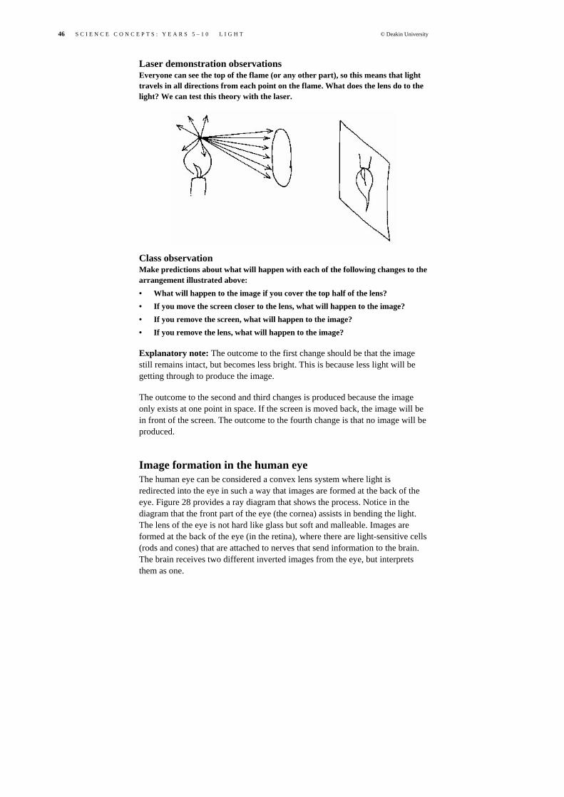
46 S C I E N C E C O N C E P T S : Y E A R S 5 – 1 0 L I G H T © Deakin University
Laser demonstration observations Everyone can see the top of the flame (or any other part), so this means that light travels in all directions from each point on the flame. What does the lens do to the light? We can test this theory with the laser.
Class observation Make predictions about what will happen with each of the following changes to the arrangement illustrated above: • What will happen to the image if you cover the top half of the lens? • If you move the screen closer to the lens, what will happen to the image? • If you remove the screen, what will happen to the image? • If you remove the lens, what will happen to the image?
Explanatory note: The outcome to the first change should be that the image still remains intact, but becomes less bright. This is because less light will be getting through to produce the image.
The outcome to the second and third changes is produced because the image only exists at one point in space. If the screen is moved back, the image will be in front of the screen. The outcome to the fourth change is that no image will be produced.
Image formation in the human eye The human eye can be considered a convex lens system where light is redirected into the eye in such a way that images are formed at the back of the eye. Figure 28 provides a ray diagram that shows the process. Notice in the diagram that the front part of the eye (the cornea) assists in bending the light. The lens of the eye is not hard like glass but soft and malleable. Images are formed at the back of the eye (in the retina), where there are light-sensitive cells (rods and cones) that are attached to nerves that send information to the brain. The brain receives two different inverted images from the eye, but interprets them as one.

© Deakin University S C I E N C E C O N C E P T S : Y E A R S 5 – 1 0 L I G H T 47
In relation to the formation of an image in the eye, consider the following: • When focusing a camera, we change the distance between the lens and the
photographic film. By what process does the eye focus? Obviously our eyes don’t bulge or retract into their sockets when we look at far and near objects.
• What is the ‘blind spot’? Why do we need to be aware of our blind spots when driving a car?
• How do some of the common eye diseases affect our vision? Consider colour-blindness, myopia, hyperopia, cataracts and glaucoma.
• How do we perceive colour? Why is our night vision only in shades of grey?
Light as electromagnetic radiation Light is produced by the movement of electrical charges. A single electrical charge (like an electron) creates a force field around it that extends out in space. This force field, called an ‘electrical field’, is a region in space such that if another electrical charge comes into that field it will either be attracted or repelled by the other charge. If we move an electrical charge, a ripple effect is set up in the electrical field around it. This is like disturbing the surface of water; you set up waves that travel in all directions from the initial disturbance. Figure 29 shows ways in which we can visualise electrical fields and the travelling disturbance.
Electromagnetic disturbance like water waves
F I G U R E 2 8 : IMA GE FOR MATI ON IN THE HU MA N
EYE
F I G U R E 2 9 : E L E C T R O -MAG NET IC WAVES
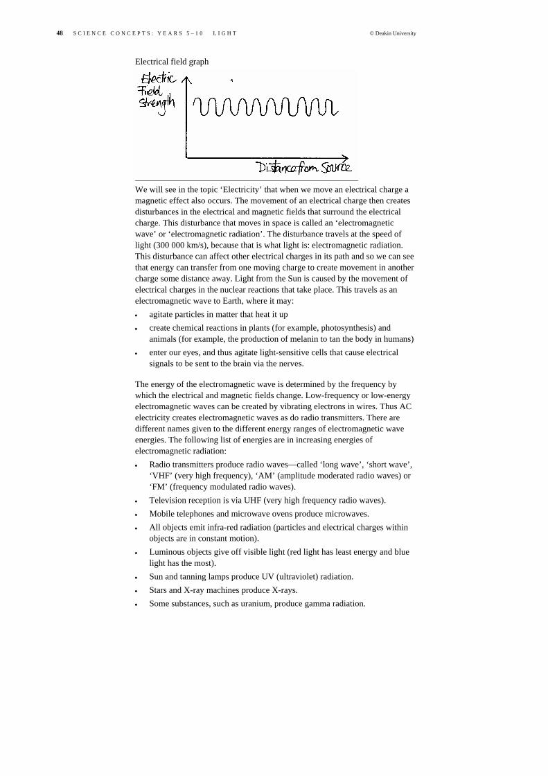
48 S C I E N C E C O N C E P T S : Y E A R S 5 – 1 0 L I G H T © Deakin University
Electrical field graph
We will see in the topic ‘Electricity’ that when we move an electrical charge a magnetic effect also occurs. The movement of an electrical charge then creates disturbances in the electrical and magnetic fields that surround the electrical charge. This disturbance that moves in space is called an ‘electromagnetic wave’ or ‘electromagnetic radiation’. The disturbance travels at the speed of light (300 000 km/s), because that is what light is: electromagnetic radiation. This disturbance can affect other electrical charges in its path and so we can see that energy can transfer from one moving charge to create movement in another charge some distance away. Light from the Sun is caused by the movement of electrical charges in the nuclear reactions that take place. This travels as an electromagnetic wave to Earth, where it may: • agitate particles in matter that heat it up • create chemical reactions in plants (for example, photosynthesis) and
animals (for example, the production of melanin to tan the body in humans) • enter our eyes, and thus agitate light-sensitive cells that cause electrical
signals to be sent to the brain via the nerves.
The energy of the electromagnetic wave is determined by the frequency by which the electrical and magnetic fields change. Low-frequency or low-energy electromagnetic waves can be created by vibrating electrons in wires. Thus AC electricity creates electromagnetic waves as do radio transmitters. There are different names given to the different energy ranges of electromagnetic wave energies. The following list of energies are in increasing energies of electromagnetic radiation: • Radio transmitters produce radio waves—called ‘long wave’, ‘short wave’,
‘VHF’ (very high frequency), ‘AM’ (amplitude moderated radio waves) or ‘FM’ (frequency modulated radio waves).
• Television reception is via UHF (very high frequency radio waves). • Mobile telephones and microwave ovens produce microwaves. • All objects emit infra-red radiation (particles and electrical charges within
objects are in constant motion). • Luminous objects give off visible light (red light has least energy and blue
light has the most). • Sun and tanning lamps produce UV (ultraviolet) radiation. • Stars and X-ray machines produce X-rays. • Some substances, such as uranium, produce gamma radiation.

© Deakin University S C I E N C E C O N C E P T S : Y E A R S 5 – 1 0 L I G H T 49
The above list forms what is known as the ‘electromagnetic spectrum’, ranging from low-energy radiation to high-energy radiation. As each form of energy travels at the speed of light, they are sometimes referred to as different forms of light. The radiation that affects our eyes is called ‘visible light’.
Electromagnetic radiation can have detrimental effects if it is absorbed into the body. The reason for this is that the absorption may interfere with the chemical reactions that occur constantly within the cells of our bodies. This may result in cell damage or the production of mutant cells. The higher the energy of the radiation that is absorbed, the greater the number of cells that can be affected. While the dangers of high exposure to high-energy radiation such as UV light, X-rays and gamma rays are well known, the high exposure of AC electricity radiation and microwave radiation from mobile phones have produced community concern in recent times. It must be pointed out that humans are exposed to each of the radiation types on a daily basis.
References Lapp, DR 1993, ‘Determining plane mirror image distance from eye charts’,
The Physics Teacher, vol. 31, pp. 59–60.