light-activated shape memory polymers: muscle actuation ...€¦ · team smp light-activated shape...
TRANSCRIPT
TEAM SMP
Light-activated shape
memory polymers: Muscle
actuation for prosthetics ENMA490 Final Report
Emily Dumm, Nesredin Kedir, Dave Newton, Zara Simpson, Hanna Walston, Erik Wienhold
5/10/2013
Abstract:
Development of advanced self-actuating prostheses is an integral part of improving the quality of life for
patients with physical disabilities. Moreover, the design of the prosthesis needs to be cost sensitive to the
manufacturer and agreeable to the patients’ financial and performance expectations. Hence, this study
aims to create a technology for arm prosthesis actuation that is affordable and highly responsive without
being excessively heavy or thermally activated. In order to accomplish these goals, we will design a shape
memory polymer (SMP) sheet for lining the interior of a prosthetic arm to induce bending upon
application of the appropriate wavelength of light. The material in our design is a liquid crystal elastomer
activated within the UV-visible range and the material in our prototype is a grafted polymer network
activated primarily by UV light. We used finite element analysis, and modeled structural and fatigue
responses of our design in order to optimize the size and composition of our design before prototyping.
Furthermore, we will perform an analysis of the two materials by comparing the advantages derived from
their performance (i.e. photo induced stress, yield strength, fatigue life, etc.) under predetermined
operating conditions. We hope to find that these SMPs are effective for use in prosthetics and may
eventually be adapted for use as robotic muscular replacements.
Team SMP ii
Contents Motivation ....................................................................................................................................... 1
Materials Science and Engineering Aspects ................................................................................... 1
Previous Work ................................................................................................................................ 2
Design Goals ................................................................................................................................... 3
Technical Approach ........................................................................................................................ 4
Introduction ................................................................................................................................. 4
Acquisition of SMP materials ..................................................................................................... 6
Design of SMP sheets ................................................................................................................. 6
Fatigue Properties ....................................................................................................................... 8
Numerical Analysis ..................................................................................................................... 9
Light Actuation of SMPs ................................................................................................................ 9
Introduction ................................................................................................................................. 9
Mechanism of Transitions........................................................................................................... 9
Azobenzene Transitions .......................................................................................................... 9
Cinnamic Acid Transitions ................................................................................................... 11
Timescale Calculations: ............................................................................................................ 12
Azobenzene Calculations ...................................................................................................... 12
Prototype ....................................................................................................................................... 16
Ethics and Environmental Impact ................................................................................................. 21
Intellectual Merit ........................................................................................................................... 22
Broader Impact.............................................................................................................................. 22
Results and Discussion ................................................................................................................. 23
Schematic model and calculation results for SMP sheet design ............................................... 23
Prosthetic arm and SMP sheet Model ....................................................................................... 28
Autodesk Simulation Multiphysics FEA Results ..................................................................... 30
Testing....................................................................................................................................... 36
Reliability of simulation results and test cases ......................................................................... 39
Future work fatigue test (optics set up) ..................................................................................... 40
Conclusions ................................................................................................................................... 41
Acknowledgements ....................................................................................................................... 41
References ..................................................................................................................................... 43
Team SMP 1
Light-activated shape memory polymers: Muscle actuation for prosthetics
Motivation
Shape memory has many promising applications in medicine, including coronary stents
and artificial muscle actuation for prosthetic limbs [Otsuka, et al., 1999; Sokolowski, et al., 2007;
Takashima, et al., 2010]. Constructively integrated and technologically advanced artificial limbs
are an important part of treatment for amputees. This type of technology can also be used for
robotics and other non-medical applications, but for the purpose of this project, we will restrict
our scope to applications relating to the human body.
Nitinol (a nickel titanium shape memory alloy) is often used in stent, orthopedic and
orthodontic applications [Fine, et al., 1998; Flomenblit, et al., 1996; Harada, et al., 1991; Hess, et
al., 1996], but metallic alloys are not sufficiently flexible for use as muscle actuators due to
weight requirements and low attainable strain levels [Behl, et al., 2007; Mather, et al., 2009;
Trepanier, et al., 1999]. These issues seem to suggest using alternative classes of materials for
bio-applications.
Shape memory polymers (SMPs) based on polyurethane have been widely used for bio-
compatible applications, but most polyurethane SMPs are thermally activated [Sokolowski, et
al., 2007]. This characteristic can present a challenge for medical applications, since thermally
induced actuation is likely to be sensitive to seasonal changes in temperature and often occurs
via non-uniform heating. In addition, thermally activated SMPs are characterized by slow
response times [Mather, et al., 2009]. Further research has investigated alternative stimuli for
activating the shape memory effect in polymers; for instance, Lee, et al. have done work with
liquid crystalline polymer networks (LCN) that can be actuated by application of different
polarizations of light [Lee, et al., 2012; Lee, et al., 2011]. White, et al. have found that light-
activated transitions can take place more quickly than thermal transitions [White, et al., 2008].
Hence, use of a light based stimulus enables rapid, precise, and remote control over the actuation
of SMPs.
Shape memory can be used to imitate muscles, as shown in Takashima’s work on
McKibben actuators [Takashima, 2010]. This work used thermal transitions to actuate the SMP,
but found them to be bulky, noisy and in need of further research. However, this article shows
that using SMPs is feasible for the purpose of creating artificial muscles since they can provide
the mechanical properties that an artificial muscle needs to have [Takashima, 2010].
Based on this background and the medical need for prosthetic muscle actuators, this
project seeks to design and prototype a shape memory polymeric material that could be used to
function like a muscle in a prosthetic arm.
Materials Science and Engineering Aspects
Many Materials Science and Engineering aspects were prevalent throughout our design,
prototyping, and testing processes. We reached into our previous knowledge of kinetics,
chemistry, reliability, and mechanics, among others. To determine the ideal light source to
activate the azobenzene SMP, a series of calculations were used to determine the number of
photons needed per square centimeter and how the angle of the light irradiating the sample
affected activation. This led us to the ideal power and wavelength the light source should
possess. Once this was determined, using kinetics, a timescale of the activation and relaxation of
the azobenzene could be developed from the amount of photons irradiating the sample per a
second.
Team SMP 2
When developing a prototype of our design, we had to take into account the different
chemicals being used so the desired properties could be obtained. We needed a SMP with similar
properties to azobenzene that was much less expensive, to make the project more cost effective
and to stay within our allotted budget. This brought us to prototyping with a cinnamic acid based
SMP, using HEA-CA as the polymer precursor with photoactive groups because it was similarly
actuated by light and could be designed to exert a similar force as azobenzene.
Many mechanical properties of the azobenzene SMP were taken into consideration
during this design process. Samples were modeled to measure the von Mises stress, von Mises
strain, and the response to fatigue. This allowed us to determine the optimal thickness of the
azobenzene SMP strip to be used in the proposed prosthetic arm. Also by taking the stress, strain,
and fatigue into account we were able to look into the reliability of the SMP strips to be able to
give an estimated number of cycles to failure.
There were certainly aspects of chemistry, physics and mathematics throughout our
project, but the overall design process and the parameters that were important to us are
characteristic of Materials Science and Engineering.
Previous Work
Research done by Behl, et al. gives a large amount of background information on shape
memory polymers, from describing the general concepts of shape memory polymers, to how they
can be thermally and light actuated. Most shape memory polymers are heat actuated resulting in
thermally induced cleavage of additional cross-links [Behl, et al., 2007]. If the cross-links are
functional groups that are able to undergo photoreversible reactions, this shape memory
mechanism can be light actuated. It also covers research on biomedical applications of shape
memory polymers, ranging from a device used for the mechanical removal of blood clots, to a
device used for measuring the ear canal to properly fit hearing aids. Behl’s paper also explains
research that has been done on the use and mechanisms of biodegradable shape memory
polymers. These biodegradable shape memory polymers can be used in minimally invasive
surgery as an intelligent suture for wound closure.
Azobenzene liquid crystals specifically undergo a transformation from a trans isomer to a
cis isomer when exposed to certain wavelengths of light. This causes a change in shape as the
molecular length of the azobenzene unit changes from 9 Å to 4 Å [Sokolowski, et al., 2007] If
the light is linearly polarized the sample will contract parallel to the polarization direction. The
wavelength of light often used for the initiation of this transformation is in the UV light range
(360nm.) This transformation can be reversed by exposing the sample to visible light (450),
which causes a trans-cis conversion. Bunning et al found that the cis-trans transformation could
be achieved by subjecting the sample to a higher wavelength argon-ion laser light of 457-514nm.
In this study it was found that using light with wavelength in this range was advantageous
because the trans-cis-trans reorientation is rapid and effective at temperatures below the glass
transition temperature of the polymer.
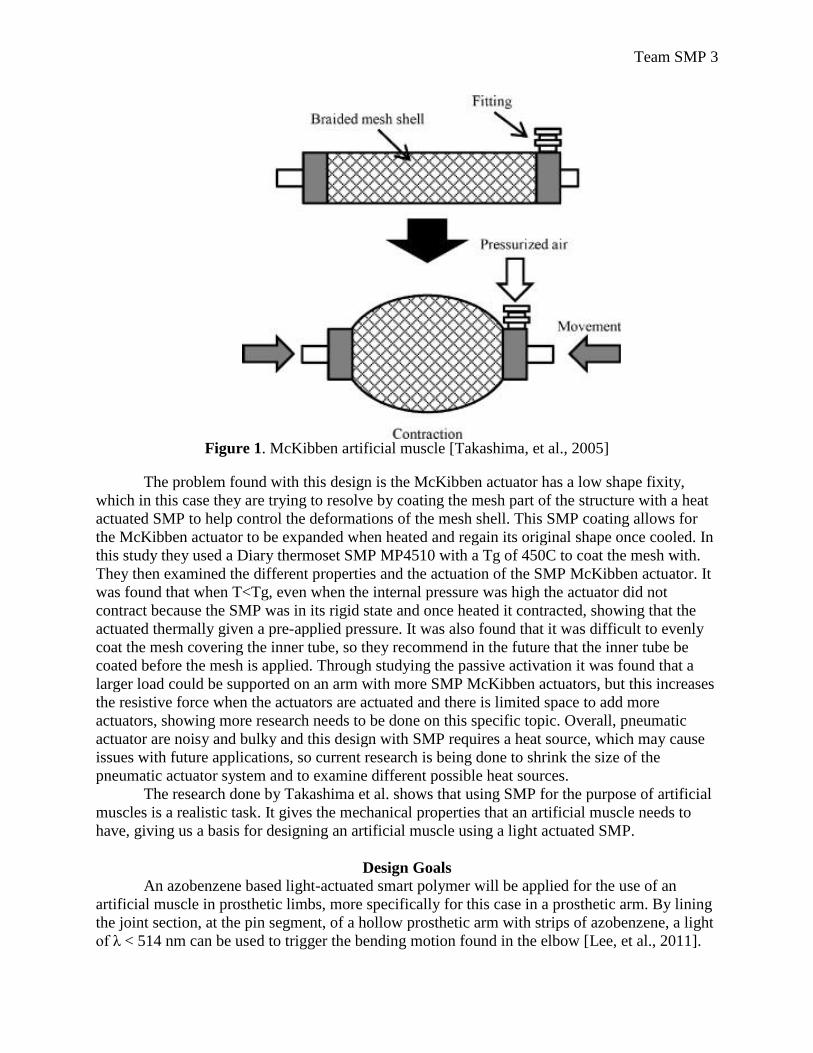
Research completed by Takashima et al. examines using a McKibben artificial muscle
impregnated with a SMP actuated by heat. A McKibben artificial muscle, shown in figure 1, is a
structure that consists of an inner bladder (e.g. rubber tube) wrapped in a flexible braided mesh,
typically fiberglass or nylon mesh. When air goes into the McKibben actuator it causes it to
contract, like a natural muscle, and when the air is released it relaxes back to its cylinder shape.
Team SMP 3
Figure 1. McKibben artificial muscle [Takashima, et al., 2005]
The problem found with this design is the McKibben actuator has a low shape fixity,
which in this case they are trying to resolve by coating the mesh part of the structure with a heat
actuated SMP to help control the deformations of the mesh shell. This SMP coating allows for
the McKibben actuator to be expanded when heated and regain its original shape once cooled. In
this study they used a Diary thermoset SMP MP4510 with a Tg of 450C to coat the mesh with.
They then examined the different properties and the actuation of the SMP McKibben actuator. It
was found that when T<Tg, even when the internal pressure was high the actuator did not
contract because the SMP was in its rigid state and once heated it contracted, showing that the
actuated thermally given a pre-applied pressure. It was also found that it was difficult to evenly
coat the mesh covering the inner tube, so they recommend in the future that the inner tube be
coated before the mesh is applied. Through studying the passive activation it was found that a
larger load could be supported on an arm with more SMP McKibben actuators, but this increases
the resistive force when the actuators are actuated and there is limited space to add more
actuators, showing more research needs to be done on this specific topic. Overall, pneumatic
actuator are noisy and bulky and this design with SMP requires a heat source, which may cause
issues with future applications, so current research is being done to shrink the size of the
pneumatic actuator system and to examine different possible heat sources.
The research done by Takashima et al. shows that using SMP for the purpose of artificial
muscles is a realistic task. It gives the mechanical properties that an artificial muscle needs to
have, giving us a basis for designing an artificial muscle using a light actuated SMP.
Design Goals
An azobenzene based light-actuated smart polymer will be applied for the use of an
artificial muscle in prosthetic limbs, more specifically for this case in a prosthetic arm. By lining
the joint section, at the pin segment, of a hollow prosthetic arm with strips of azobenzene, a light
of λ < 514 nm can be used to trigger the bending motion found in the elbow [Lee, et al., 2011].
Team SMP 4
The azobenzene can then be photochemically relaxed in a matter of picoseconds. This creates a
realistic bending motion of the elbow in a reasonable amount of time.
The pin segment, located at the joint of the elbow, can accommodate four SMP strips,
each with a width of 0.75 cm and a length of 4.5 cm. The light source required for shape
activation will line the pin segment of the prosthetic arm to rapidly irradiate the SMP to allow for
prompt actuation, simulating the bending motion of an elbow.
Autodesk Simulation Multiphysics software will be used to model the azobenzene strips
to measure the Von Mises stress, Von Mises strain, and the fatigue response to cyclic loading.
Azobenzene samples, provided by Timothy White (J Civ, USAF, AFMC, AFRL/RXAP) will
then be tested in various ways. Dynamic mechanical analysis (DMA) will be used for our
azobenzene samples’ stress strain curves. Multiple light sources including, a medium pressure
mercury lamp (418 nm), a laser (473 nm), and an UV lamp (365 nm) will all be used to test for
the actuation and relaxation of the azobenzene. This will allow us to better understand the
amount of force the artificial muscle will be able to exert in order to understand the total amount
the prosthetic arm will be capable of lifting.
SMP have not yet been applied directly for the use of muscle actuation in prosthetic
limbs. There have been other mechanical mechanisms used to act as muscles, such as the
McKibben Artificial muscle, which was discussed earlier in the previous work section. This type
of artificial muscle uses air to cause the artificial muscle fibers to contract and relax like a real
muscle. There has been research on the use of SMP to coat the McKibben actuator to help
increase the shape fixity.
Technical Approach
Introduction
The three most prevalent forms of photoactivation of shape memory polymers are
photoisomerization of azobenzene, photoreversible covalent crosslinking via photoreactive
cinnamate-type groups, and infrared thermal activation [Jiang, et al., 2006]. Thermal activation
of shape memory polymers has been well documented and widely used, however direct
photocrosslinking and photoisomerization are not as prevalent [Behl, et al.,2007 ; Mather, et al.,
2009]. The response of azobenzene liquid crystal (LC) networks to light stimuli is based on the
trans-cis or cis-trans isomerization of azobenzene molecules [Leng, et al., 2011]. In the trans
configuration, azobenzene is thermodynamically stable and retains a length of 9 Å measured
between the tips of its two benzene rings [Iqbal, et al., 2013]. When this trans-azobenzene is
irradiated with a light source intermediate between the UV and visible range, it isomerizes to a
metastable cis conformer and the effective length between the tips of the benzene rings is
reduced by 4 Å. Since the azobenzene molecules are covalently bonded to the liquid crystal
network, the contraction and expansion of the azobenzene is observed in the macroscale.
Similarly, photoreactive cinnamate-type groups respond to light stimuli; however, these
stimuli are generally confined to the UV range [Conjugated, et al., 2005]. The cinnamate-type
groups are commonly incorporated into polymer chains by means of a chemical reaction between
monomers and cinnamic acid or cinnamylidene acetic acid [Conjugated, et al., 2005]. In contrast
to azobenzene SMPs, the cinnamate groups form reversible photocrosslinks to induce a shape
memory effect [Jiang, et al., 2006]. As a result, the polymer becomes macroscopically stable at
an intermediate deformed shape, instead of relaxing to its initial undeformed state.
Theoretical models for the photo-induced deformation of azobenzene are well-
documented by Saphiannikova, et al. and Cheng et al. [Toshchevikov, et al., 2009; Cheng, et al.,

Team SMP 5
2012]. According to these references, the deformation of azobenzene is dependent on the
direction of the electric field component of a linearly polarized light [Toshchevikov, et al., 2009].
The linearly polarized light utilizes the orientational anisotropy associated with the cis-to-trans
isomerization of azobenzene chromophores. As a result, deformation of the SMP or the cis-to-
trans conversion of the covalently-bonded, light-receptive chromophores has the highest
probability of occurrence when the polymer chains are oriented along the electric field of a
linearly polarized light. The reverse isomerization or recovery of the pre-deformed shape occurs
by thermally induced relaxation. However, the rate of the shape recovery ranges from hours to
days under standard conditions (298 K and 1 atm). Hence, the process is usually accelerated by
exposing the SMP to a light source with wavelengths in the visible range. The irradiated light is
more localized and hence capable of transferring the energy required for the reverse
isomerization with minimal losses due to reflection and transmission. Figure 2 provides a visual
summary of the shape memory mechanism for azobenzene SMPs.
Figure 2: A model for the reversible photo-isomerization of an azobenzene molecule [Jiang, et
al., 2006]
In contrast, there is no well-defined study focused on theoretical modeling for the photo-
induced deformation of cinnamate group shape memory polymers. However, photomechanical
studies by Lendlein et al. and Du et al., as well as a review by Long et al. provide a credible
mechanism for the shape memory properties of cinnamate group SMPs [Lendlein, et al., 2005;
Du, et al., 2012; Long, et al., 2009]. The proposed mechanism is best illustrated in two parts. The
first part consists of shape fixing or establishing the intermediate shape in which the SMP sample
is subject to an external elastic strain. This is usually performed by placing the sample in tension
under a constant load [Behl, et al., 2007], or by elastically deforming the sample into a helical
shape [Du, et al., 2012]. The strained sample is then set as the intermediate shape by irradiation
of light with λ > 260 nm [Conjugated, et al., 2005; Du, et al., 2012]. Although there is no
prescribed wavelength for this process, Du et al. was able to show that light with a wavelength of
360 nm (1.731x10¹⁷
photons/m2) is capable of fixing the intermediate shape of a helically
deformed SMP [Du, et al., 2012]. During the irradiation of light, the photoreceptive cinnamate
chromophores in the SMP dimerize to form chemical crosslinks that reinforce the strained shape.
Once the light source is removed, the strained shape will not revert to its original/memory shape.
The shape recovery of the SMP is the second part if the proposed mechanism, in which UV light
with λ < 260 nm is used to induce this transition. Just as with the shape fixing process, there is no
prescribed wavelength for shape recovery; however, Jiang et al. successfully utilized a UV light
source with a wavelength of 254 nm (1.221x10¹⁷
photons/m2) [Jiang, et al., 2006] to recover the
Team SMP 6
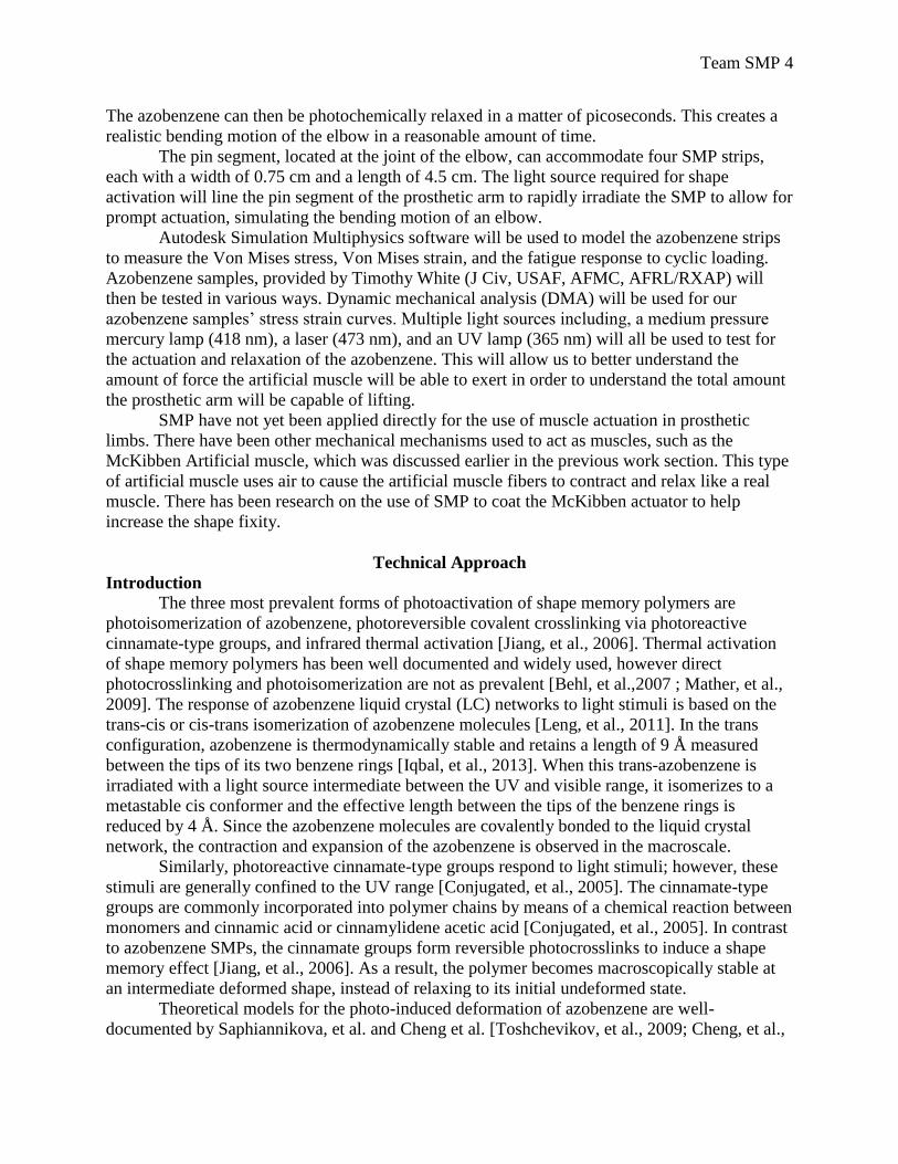
unstrained SMP shape. Unlike the irradiation of light with λ > 260, the low-wavelength UV light
cleaves the crosslinks formed by the cinnamate photoreceptive chromophores. Figure 3 provides
a visual summary of the mechanism for the shape memory of light activated cinnamate group
SMPs outlined in the preceding discussion [Jiang, et al, 2006].
Figure 3: A model for the reversible photo-crosslinking of cinnamate group molecules [Jiang, et
al., 2006]
In our efforts to design and model both azobenzene and cinnamate group SMPs for
artificial muscle actuation, we will focus on the responses that are specific to the design instead
of a theoretical analysis of the mechanism for light induced shape memory effect. The two most
important responses we will attempt to model are structural response to applied stress and fatigue
response from cyclical loading. Structural responses are useful in determining the uniformity of
induced strains and relative displacements, while fatigue response provides an approximate
lifetime for the part in terms of numbers of loading cycles until failure. Prior to modeling these
responses, we will determine the optimum size and load exerted by a hollow high density
polypropylene prosthetic limb on rectangular sheets of the SMP.
Acquisition of SMP materials
Since we will be working with two types of SMPs in this project, creating parallel
designs, there are two different routes by which we will obtain our materials. The prototyping
section of our paper details the synthesis procedure of the cinnamic acid SMP. The procedures to
synthesize 2-Hydroxyethyl acrylate-cinnamic acid (HEA-CA) were provided by Dr. Marc Behl,
a Chemist and head of the “Active Polymers” Department at the Institute of Biomaterials Science
in Helmholtz-Zentrum Geesthacht, Germany. The procedures for co-polymerization of the
HEA-CA and 2-Hydroxyethyl methacrylate (HEMA) monomers to form the prototype are
borrowed from the study by Lendlein et al. [Lendlein, et al., 2005].
We were not successful in our attempt to contact various researchers to provide us with
the azobenzene liquid crystal monomers in order to carry out our own polymerization. However,
one of the researchers we contacted (Dr. Timothy White) has been kind and willing enough to
donate samples of the azobenzene SMP used in his study [Lee, et al., 2011].
Design of SMP sheets
The optimal sizing and design of an SMP sheet will be based on dimensions for an
average human arm. The desired information is readily available in a report compiled by R.F
Chandler for the U.S. Department of Transportation. In addition, the geometry of each
component that constitutes the arm (upper arm, forearm and hand) will be approximated as a
Team SMP 7
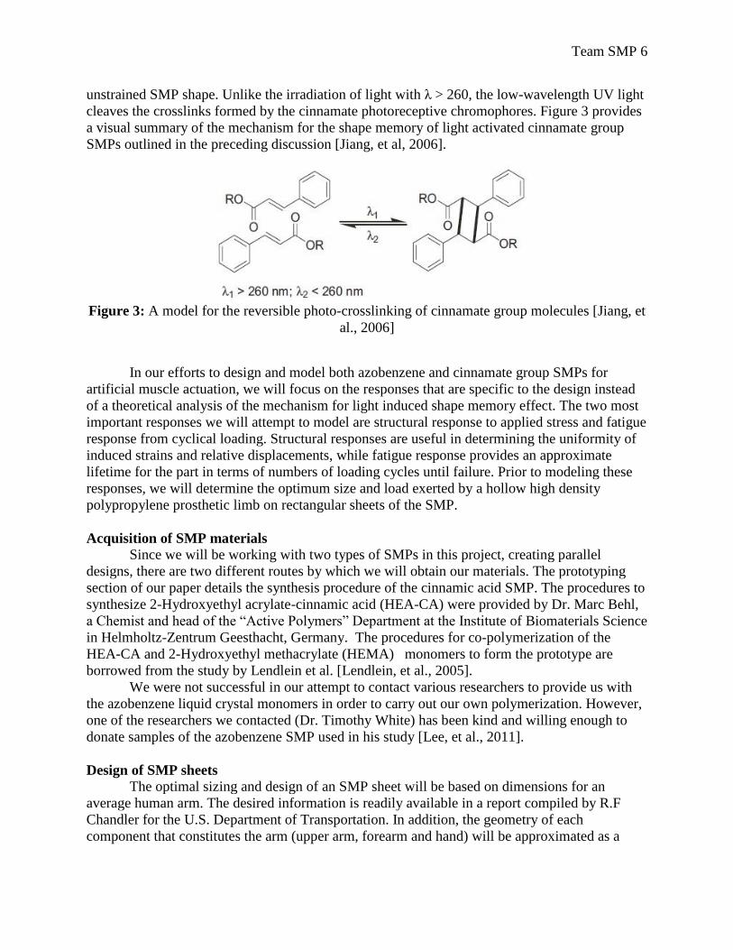
tapered hollow cylinder as shown in Figure 4. The volume of these cylinders will be determined
by initially obtaining a volume of a cone using the following equation
, (1)
where is the inner radius of the cone base, is the outer radius of the cone base, h is the
desired height of the anatomy and is the extra length added to form the tapered cylinder. The
volume obtained using equation ( ) is then decreased by the volume of a cone with a height using the following equation,
(2)
where and are respectively the inner and outer radius of the cone.
Figure 4: Tapered cylinder geometry
In most instances, the material of choice for a prosthetic arm is high density
polypropylene [Programme]. Hence, the mass for the model of an arm retaining the geometry
described above will be determined using the density of commercially available polypropylene
( ). The weight of each arm segment is then determined by the following formula,
(3)
where 9.81 ms-2
is the acceleration due to gravity.
The estimated weight of the polypropylene prosthetic arm generates a bending moment
that must be overcome by the SMP in order to mimic the bending motion. The photo-induced
bending stresses ( ) generated in the azobenzene SMPs during photo-induced deformation is
obtained from reported experimental observations by Cheng et al. [Cheng, et al., 2012; Jiang, et
al., 2006]. The photo-induced bending stress for the cinnamate group SMPs is not available from
previous literature and it must be obtained via mechanical tests on synthesized and grafted
prototypes. The force produced by the SMP is obtained using the following expression,
(4)
where represents the surface area of the SMP sheet. In our design, we will create a model of a
prosthetic arm using the arm dimensions provided by Chandler et al. and use the model to
estimate the optimal surface area of the SMP sheets. Subsequently, equation (4) will be used to
Team SMP 8
estimate of the photo-induced bending force. In order to create a functional arm prosthesis, the
magnitude of the force from the artificial SMP muscle must be large enough to produce a
bending moment that exceeds the moment generated by the weight of the prosthetic arm and any
additional moments resulting from carried loads.
Fatigue Properties
The synthetic muscle actuator formed by either azobenzene or cinnamate group SMPs
will experience large numbers of cyclical loadings during operation. This is based on the fact that
the SMP must overcome the weight of the polypropylene prosthetic arm as it bends in response
to light stimulus. It is assumed in this case that the fully extended arm at 0˚ represents a state of
minimum stress in the cycle ( ) and the fully contracted arm represents a state of maximum
stress ( ). Since the fully extended arm does not exert require a force on from the SMP it
implies a value of zero. As a result, the stress range given by the following expression,
, (5)
is equal to the maximum stress. Consequently, the stress amplitude, which is defined as half of
the stress range, is given by half of the maximum stress,
=
. (6)
The mean stress ( , which is given by the average of the maximum and minimum stress,
becomes equivalent to the stress amplitude by the same reasoning, and is thus expressed by
equation (6).
The fatigue properties of polymers, in terms of stress amplitude and fatigue life are very
similar to those of relatively ductile metals [Programme]. Hence, equations for the high cycle
and low cycle fatigue life developed for metals are used to model the fatigue life of the polymers
in our study. In the high cycle fatigue range, where the applied strain is the lowest and many
cycles have occurred, only elastic strains ( ) act on the material and the strain response is
related to the number of cycles through:
=
(7)
where is the modulus, 2 is the reversals to failure (1 rev. = 0.5 cycles) and the constants
and b are respectively the fatigue strength coefficient and the fatigue strength exponent
[Courtney, 1990; Autodesk]. Due to a lack of previous studies on the fatigue properties of
azobenzene and cinnamate group SMPs, we need to conduct a strain-based fatigue analysis to
obtain the values of these constants. In the low cycle or high strain fatigue range, plastic strains
( ) are predominantly active and the strain response is related to the number of cycles by the
Coffin-Manson relation [Programme],
=
(8)
Team SMP 9
where is a constant with a value close to the tensile ductility , and the c is a constant value that
ranges between 0.5 and 0.7. The constants b and c are also closely related to the strain hardening
coefficient (n’) of the material. The relationship between the strain amplitude (
and number of cycles to failure is termed the Morrow design rule [Ekberg]. This relation
can be used to generate a strain-cycle curve and fatigue life estimates for ductile metals and
polymers.
Numerical Analysis
The modeling of these SMPs requires the understanding of their mechanical properties
both statically and dynamically. To further understand how they will behave, we began by
constructing a 3D model for a thin sheet. This model was then used to perform structural Finite
Element Analysis (FEA). Autodesk Inventor was used as the primary software to create the 3D
model. Although Inventor has the capabilities to perform basic FEA for stress, strain and
displacement simulations, it is not capable of performing a fatigue analysis. Hence, we will use
Autodesk Simulation Multiphysics software to perform all necessary FEA simulations.
Light Actuation of SMPs
Introduction
There are two different mechanisms of activation for the two types of shape memory
polymers (SMPs) used in our project. Azobenzene, the primary material used in our design, is
actuated by a cis-trans conformational change caused by application of the appropriate
wavelength of blue light. After the polymer is activated, it can be returned to its original or
memorized state by either of two mechanisms: photo-conversion and thermal relaxation. The
photo-conversion can be by exposure to ambient light accomplished using circularly polarized
light, as in Lee, et al [Lee, et al., 2011]. The thermal relaxation transition is accomplished by
motion in vibrational modes. The light used may be of the same wavelength, but its circular
polarization ensures that its orientation is random, in contrast to the directionality of the previous
activation. From the wattages given in the literature, the photon flux for the given azobenzene
activation and relaxation times can be calculated. These values can then be used to calculate
activation and relaxation times for the light sources we have at our disposal. Similarly,
activation and relaxation times can be calculated for the cinnamic acid-based SMPs; however,
their activation mechanism is very different. They operate by forming crosslinks between
adjacent polymer chains when irradiated at a wavelength > 260 nm [Lendlein, et al., 2005].
Afterward, irradiation with a wavelength < 260 nm cleaves the crosslinks and reverses the
macroscopic changes [Lendlein, et al., 2005].
Mechanism of Transitions
Azobenzene Transitions
As shown in [Tiago, et al., 2005], azobenzene-based SMPs have two different electron
excitation modes, via the Frank-Condon principle. However, instead of separation distance
between atoms (r), these excitations are associated with the rotation of the carbon-nitrogen bonds
between the benzene ring and the double-bonded nitrogen atoms. Each dihedral angle essentially
contributes to one degree of freedom, resulting in 3 degrees of freedom for C-N rotation. For the
first excited state, electrons are transitioned from the highest occupied molecular orbital
(HOMO) to the lowest unoccupied molecular orbital (LUMO). This occurs near the nitrogen
atoms, where the LUMO is an antibonding orbital.
Team SMP 10
At the ground state, the trans conformation is at a lower energy than the cis conformation.
The metastable cis conformation is ~ 0.6 eV above the trans conformation, with the activation
energy for the trans-cis conformation being higher than 1 eV [Tiago, et al., 2005]. The potential
energy surface at the ground state has a saddle point between the cis and trans conformations,
determined by density functional theory (DFT) calculations to be 1.67 eV and indicated by
experiments to lie in the range between 1.45-1.75 eV [Tiago, et al., 2005]. This saddle point
indicates the energy at which the system can isomerize with almost no activation energy, due to
its excitation. Therefore we expect to see the conformation freely switching between the cis and
trans conformations at equal probabilities while the system is in the first excited state. In the
second excited state, on the other hand, there is no structural change expected unless it first
decays to the first excited state by emission of a photon. This has never been observed
experimentally via time-resolved UV-visible spectroscopy, since the energy required to reach the
second excited state is significantly higher than that of the first excited state [Tiago, et al., 2005].
The initial optical excitation of the azobenzene system is due to interaction between
electrons and photons while in the ground state. Irradiation of azobenzene SMPs with the
appropriate wavelength ( 320 - 514 nm) and intensity of light leads to excitation of the molecules
from the ground state to the first excited state [Lee, et al., 2011]. While in the first excited state,
the system seeks to reach the minimum for the excited potential energy surface by transitioning
to lower vibrational modes (i.e. emission of phonons). It goes through a number of these energy
transitions to reach the minimum energy (shown as S1AB in the figure below). Upon reaching
the minimum, the system can continue to dissipate energy through lower vibrational modes to
return to the ground state, or it can be energized to reach the other conformation while remaining
in the first excited state. It is the latter which we propose to do by means of switching
polarization direction of the applied light. According to Merino et al., the cis-trans or trans-cis
transitions occur very quickly when photo-initiated, on the order of picoseconds, but thermal
relaxations can take much longer, ranging anywhere from milliseconds to days [Merino, et al.,
2012]. Making use of the photochemical transitions instead of leaving enough time for the
vibrational or thermal transitions to occur allows more control of the timescale of the transitions
as well as the conformation of the system.
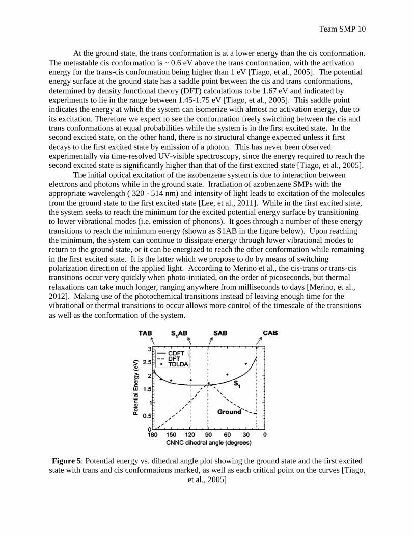
Figure 5: Potential energy vs. dihedral angle plot showing the ground state and the first excited
state with trans and cis conformations marked, as well as each critical point on the curves [Tiago,
et al., 2005]
Team SMP 11
As the excited system relaxes toward the S1AB minimum energy point, it approaches an
energy value of 1.67 eV around a dihedral angle of 120 degrees. This is sufficiently similar to
the saddle point for the ground state potential surface (found at 1.67 eV around 90 degrees) that
it allows easy transition between the first excited and ground states without necessarily requiring
emission or absorption of a photon. This can be seen by the fact that the S1 curve contacts the
ground state curve at its maximum. Furthermore, the symmetry of the plot suggests that we can
expect to see approximately equal numbers of each transition type (trans-trans, trans-cis, cis-
trans, and cis-cis). In order to induce preference in the system for the particular transition we
want, we will use polarized light to directionalize the light initiating the transition.
Cinnamic Acid Transitions
A detailed quantum chemistry analysis for the photo-induced transition in cinnamic acid
and its derivatives has yet to be performed. However, analysis of the chemical reactions outlined
in a study by Lendlein et al. can be used to surmise a simplified explanation of this transition
[Lendlein, et al., 2005]. Irradiation of light receptive cinnamate groups with a light source
generating a wavelength > 260 nm leads to the formation of photochemical cross-links between
cinnamic acid functional groups in the polymer. According to Lendlein et al., this transition
occurs by a [2+2] cycloaddition reaction in which the C=C bonds of adjacent cinnamic acid
functional groups are broken to form two new covalent bonds, and hence a cyclobutane ring
[Lendlein, et al., 2005]. From a quantum chemistry perspective, the [2+2] cycloaddition reaction
occurs when a photon is absorbed by a photoactive molecule (i.e. cinnamic acid). In the case of
cinnamic acid, the energy of the photon must be no more than 4.77 eV ( > 260 nm) to excite an
electron from both C=C bonds of the adjacent cinnamic acid functional groups from the
HOMO to the next LUMO. The HOMO for each functional group is the ground state and the
excited state is the LUMO, and for cinnamic acid it happens to be an antibonding orbital.
Hence, the transition from a ground state to an excited electronic state is responsible for the
formation of two sigma ( ) bonds or cross-links between cinnamic acid functional groups in this
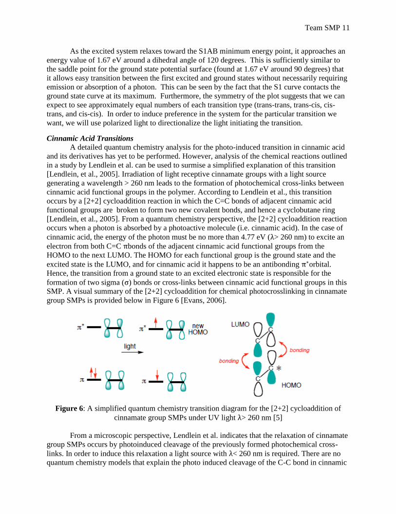
SMP. A visual summary of the [2+2] cycloaddition for chemical photocrosslinking in cinnamate
group SMPs is provided below in Figure 6 [Evans, 2006].
Figure 6: A simplified quantum chemistry transition diagram for the [2+2] cycloaddition of
cinnamate group SMPs under UV light > 260 nm [5]
From a microscopic perspective, Lendlein et al. indicates that the relaxation of cinnamate
group SMPs occurs by photoinduced cleavage of the previously formed photochemical cross-
links. In order to induce this relaxation a light source with < 260 nm is required. There are no
quantum chemistry models that explain the photo induced cleavage of the C-C bond in cinnamic
Team SMP 12
acid and we are forced to make crude approximations in our explanation of this mechanism. The
only critical information on the relaxation of cinnamic acid functional groups provided by
Lendlein et al. is that the photo cross-links are reversibly cleaved [Lendlein, et al., 2011]. Hence,
the break in the C-C sigma bond does not yield a radical as a final product but proceeds back to
the original C=C bond. Based on this we can generalize that, absorption of a photon with energy
greater than 4.77 eV ( < 260 nm) is sufficient to break the photochemical cross-link C-C bond of
the cyclobutane and yield a lone pair electron (n). The lone pair electron yields a high energy
state and a lower energy state is obtained by exciting the lone pair to a lower unoccupied
molecular orbital to reform the C=C bond. A schematic for the formation of the cross-links and
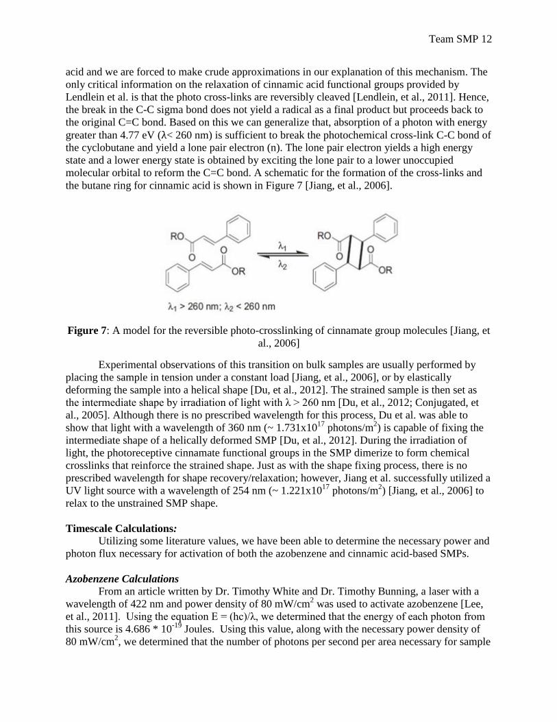
the butane ring for cinnamic acid is shown in Figure 7 [Jiang, et al., 2006].
Figure 7: A model for the reversible photo-crosslinking of cinnamate group molecules [Jiang, et
al., 2006]
Experimental observations of this transition on bulk samples are usually performed by
placing the sample in tension under a constant load [Jiang, et al., 2006], or by elastically
deforming the sample into a helical shape [Du, et al., 2012]. The strained sample is then set as
the intermediate shape by irradiation of light with λ > 260 nm [Du, et al., 2012; Conjugated, et
al., 2005]. Although there is no prescribed wavelength for this process, Du et al. was able to
show that light with a wavelength of 360 nm (~ 1.731x10¹⁷
photons/m2) is capable of fixing the
intermediate shape of a helically deformed SMP [Du, et al., 2012]. During the irradiation of
light, the photoreceptive cinnamate functional groups in the SMP dimerize to form chemical
crosslinks that reinforce the strained shape. Just as with the shape fixing process, there is no
prescribed wavelength for shape recovery/relaxation; however, Jiang et al. successfully utilized a
UV light source with a wavelength of 254 nm (~ 1.221x10¹⁷
photons/m2) [Jiang, et al., 2006] to
relax to the unstrained SMP shape.
Timescale Calculations:
Utilizing some literature values, we have been able to determine the necessary power and
photon flux necessary for activation of both the azobenzene and cinnamic acid-based SMPs.
Azobenzene Calculations
From an article written by Dr. Timothy White and Dr. Timothy Bunning, a laser with a
wavelength of 422 nm and power density of 80 mW/cm2 was used to activate azobenzene [Lee,
et al., 2011]. Using the equation E = (hc)/λ, we determined that the energy of each photon from
this source is 4.686 * 10-19
Joules. Using this value, along with the necessary power density of
80 mW/cm2, we determined that the number of photons per second per area necessary for sample
Team SMP 13
activation is equal to 1.707*1021
. Based on this result, we were able to multiply by the area of
our sample, which is 3.375 * 10-4
m2 to obtain the photon flux necessary for our sample to be
activated. The resultant value came out to be ~5.76 * 1017
photons/sec.
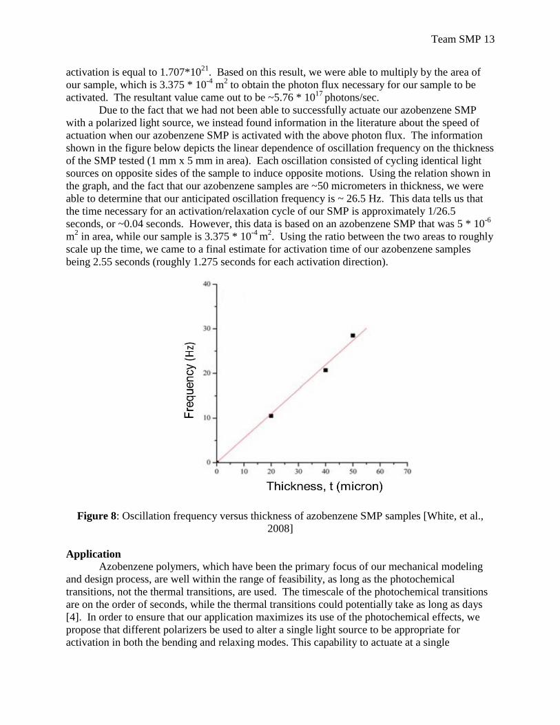
Due to the fact that we had not been able to successfully actuate our azobenzene SMP
with a polarized light source, we instead found information in the literature about the speed of
actuation when our azobenzene SMP is activated with the above photon flux. The information
shown in the figure below depicts the linear dependence of oscillation frequency on the thickness
of the SMP tested (1 mm x 5 mm in area). Each oscillation consisted of cycling identical light
sources on opposite sides of the sample to induce opposite motions. Using the relation shown in
the graph, and the fact that our azobenzene samples are ~50 micrometers in thickness, we were
able to determine that our anticipated oscillation frequency is ~ 26.5 Hz. This data tells us that
the time necessary for an activation/relaxation cycle of our SMP is approximately 1/26.5
seconds, or ~0.04 seconds. However, this data is based on an azobenzene SMP that was 5 * 10-6
m2 in area, while our sample is 3.375 * 10
-4 m
2. Using the ratio between the two areas to roughly
scale up the time, we came to a final estimate for activation time of our azobenzene samples
being 2.55 seconds (roughly 1.275 seconds for each activation direction).
Figure 8: Oscillation frequency versus thickness of azobenzene SMP samples [White, et al.,
2008]
Application Azobenzene polymers, which have been the primary focus of our mechanical modeling
and design process, are well within the range of feasibility, as long as the photochemical
transitions, not the thermal transitions, are used. The timescale of the photochemical transitions
are on the order of seconds, while the thermal transitions could potentially take as long as days
[4]. In order to ensure that our application maximizes its use of the photochemical effects, we
propose that different polarizers be used to alter a single light source to be appropriate for
activation in both the bending and relaxing modes. This capability to actuate at a single
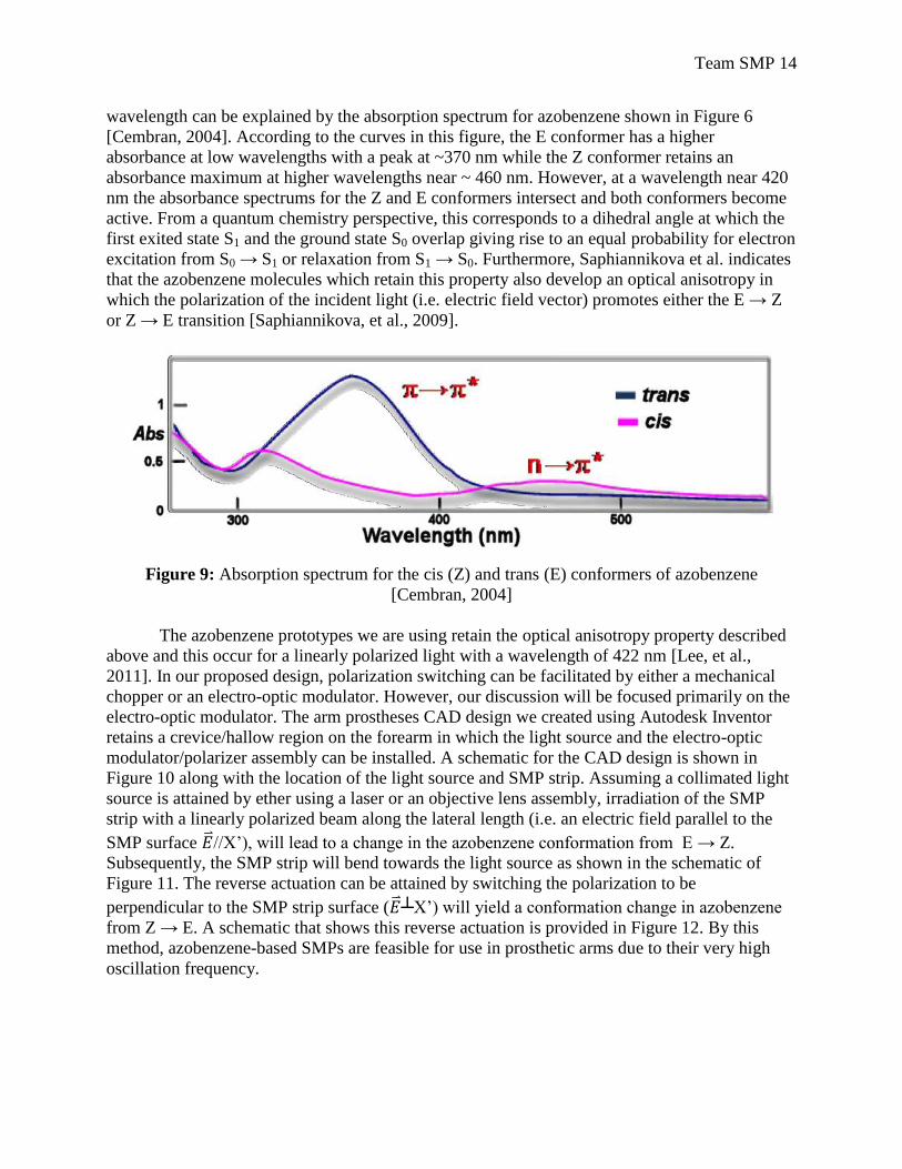
Team SMP 14
wavelength can be explained by the absorption spectrum for azobenzene shown in Figure 6
[Cembran, 2004]. According to the curves in this figure, the E conformer has a higher
absorbance at low wavelengths with a peak at ~370 nm while the Z conformer retains an
absorbance maximum at higher wavelengths near ~ 460 nm. However, at a wavelength near 420
nm the absorbance spectrums for the Z and E conformers intersect and both conformers become
active. From a quantum chemistry perspective, this corresponds to a dihedral angle at which the
first exited state S1 and the ground state S0 overlap giving rise to an equal probability for electron
excitation from S0 → S1 or relaxation from S1 → S0. Furthermore, Saphiannikova et al. indicates
that the azobenzene molecules which retain this property also develop an optical anisotropy in
which the polarization of the incident light (i.e. electric field vector) promotes either the E → Z
or Z → E transition [Saphiannikova, et al., 2009].
Figure 9: Absorption spectrum for the cis (Z) and trans (E) conformers of azobenzene
[Cembran, 2004]
The azobenzene prototypes we are using retain the optical anisotropy property described
above and this occur for a linearly polarized light with a wavelength of 422 nm [Lee, et al.,
2011]. In our proposed design, polarization switching can be facilitated by either a mechanical
chopper or an electro-optic modulator. However, our discussion will be focused primarily on the
electro-optic modulator. The arm prostheses CAD design we created using Autodesk Inventor
retains a crevice/hallow region on the forearm in which the light source and the electro-optic
modulator/polarizer assembly can be installed. A schematic for the CAD design is shown in
Figure 10 along with the location of the light source and SMP strip. Assuming a collimated light
source is attained by ether using a laser or an objective lens assembly, irradiation of the SMP
strip with a linearly polarized beam along the lateral length (i.e. an electric field parallel to the
SMP surface //X’), will lead to a change in the azobenzene conformation from E → Z.
Subsequently, the SMP strip will bend towards the light source as shown in the schematic of
Figure 11. The reverse actuation can be attained by switching the polarization to be
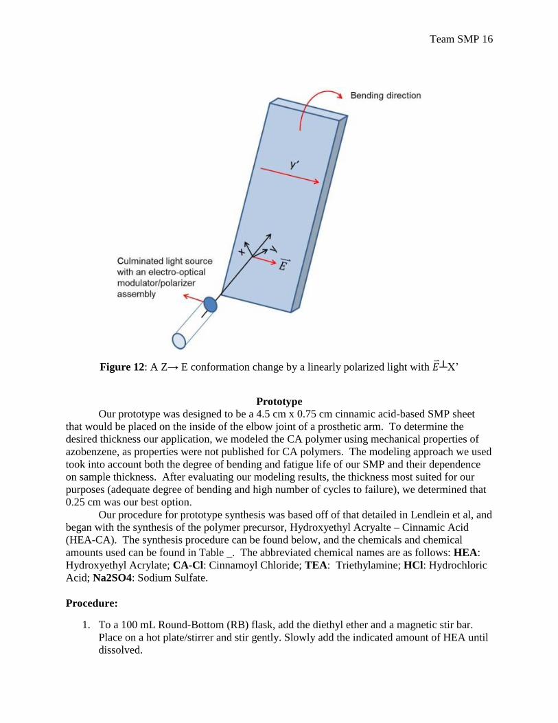
perpendicular to the SMP strip surface ( ┴X’) will yield a conformation change in azobenzene from Z → E. A schematic that shows this reverse actuation is provided in Figure 12. By this
method, azobenzene-based SMPs are feasible for use in prosthetic arms due to their very high
oscillation frequency.
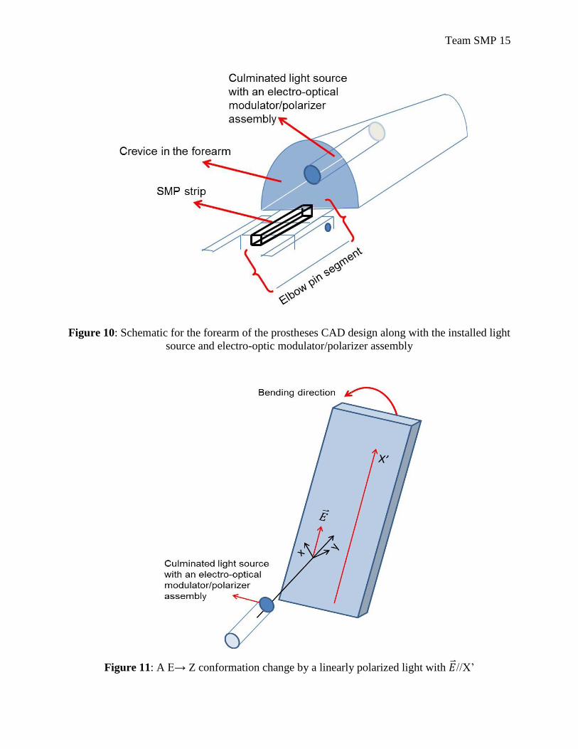
Team SMP 15
Figure 10: Schematic for the forearm of the prostheses CAD design along with the installed light
source and electro-optic modulator/polarizer assembly
Figure 11: A E→ Z conformation change by a linearly polarized light with //X’
Team SMP 16
Figure 12: A Z→ E conformation change by a linearly polarized light with ┴X’
Prototype
Our prototype was designed to be a 4.5 cm x 0.75 cm cinnamic acid-based SMP sheet
that would be placed on the inside of the elbow joint of a prosthetic arm. To determine the
desired thickness our application, we modeled the CA polymer using mechanical properties of
azobenzene, as properties were not published for CA polymers. The modeling approach we used
took into account both the degree of bending and fatigue life of our SMP and their dependence
on sample thickness. After evaluating our modeling results, the thickness most suited for our
purposes (adequate degree of bending and high number of cycles to failure), we determined that
0.25 cm was our best option.
Our procedure for prototype synthesis was based off of that detailed in Lendlein et al, and
began with the synthesis of the polymer precursor, Hydroxyethyl Acryalte – Cinnamic Acid
(HEA-CA). The synthesis procedure can be found below, and the chemicals and chemical
amounts used can be found in Table _. The abbreviated chemical names are as follows: HEA:
Hydroxyethyl Acrylate; CA-Cl: Cinnamoyl Chloride; TEA: Triethylamine; HCl: Hydrochloric
Acid; Na2SO4: Sodium Sulfate.
Procedure:
1. To a 100 mL Round-Bottom (RB) flask, add the diethyl ether and a magnetic stir bar.
Place on a hot plate/stirrer and stir gently. Slowly add the indicated amount of HEA until
dissolved.

Team SMP 17
2. To this mixture, add the CA-Cl while keeping the mixture stirring.
3. Slowly add TEA. Attach a reflux condenser to the B flask and connect water hoses.
ently heat the mixture to bring to reflux at 0 C (The BP of diethyl ether is 3 .6 ˚C).
Reflux for 3 hours while keeping the mixture stirred.
Figure 13: Setup for 3-hour reflux of solution. RB flask was uniformly heated by immersing in
temperature-controlled water bath.
4. Turn off the heat and allow the mixture to continue stirring at room temperature for 18
hours. Triethylamine hydrochloride will precipitate.
5. Filter the precipitate. Remove the solvent from the filtrate using Rotovap.
Reflux
Condenser
Water Bath

Team SMP 18
Figure 14: Rotovap used to remove excess solvent from the filtrate. Dry ice was placed in the
cold finger to allow for condensation of the diethyl ether.
6. Dissolve the residue in 50 mL of toluene and transfer to a separatory funnel. Wash the
toluene solution with 50 mL of 0.1 M* HCl once. Allow the layers to separate and
remove the bottom layer, keeping the top (toluene) layer in the sep funnel. Wash the
toluene layer with 50 mL water, allow the layers to separate, remove the lower aqueous
layer and wash the toluene layer a second time with another 50 mL of water.
Figure 15: Washing of the organic phase and removal of aqueous layer using separatory funnel.
Condensed Diethyl
Ether
Filtrate
Separatory
Funnel
Team SMP 19
7. Remove the lower aqueous layer and pour the organic layer from the top of the
separatory funnel into an Erlenmeyer flask. Dry the organic phase with anhydrous
sodium sulfate.
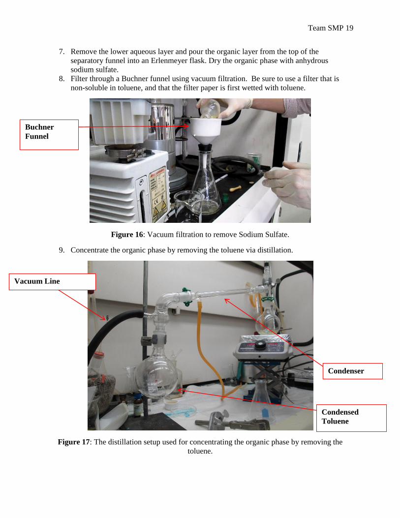
8. Filter through a Buchner funnel using vacuum filtration. Be sure to use a filter that is
non-soluble in toluene, and that the filter paper is first wetted with toluene.
Figure 16: Vacuum filtration to remove Sodium Sulfate.
9. Concentrate the organic phase by removing the toluene via distillation.
Figure 17: The distillation setup used for concentrating the organic phase by removing the
toluene.
Buchner
Funnel
Vacuum Line
Condenser
Condensed
Toluene
Team SMP 20
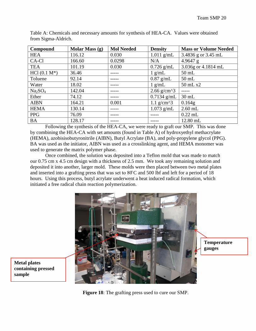
Table A: Chemicals and necessary amounts for synthesis of HEA-CA. Values were obtained
from Sigma-Aldrich.
Compound Molar Mass (g) Mol Needed Density Mass or Volume Needed
HEA 116.12 0.030 1.011 g/mL 3.4836 g or 3.45 mL
CA-Cl 166.60 0.0298 N/A 4.9647 g
TEA 101.19 0.030 0.726 g/mL 3.036g or 4.1814 mL
HCl (0.1 M*) 36.46 ----- 1 g/mL 50 mL
Toluene 92.14 ----- 0.87 g/mL 50 mL
Water 18.02 ----- 1 g/mL 50 mL x2
Na2SO4 142.04 ----- 2.66 g/cm^3 -----
Ether 74.12 ----- 0.7134 g/mL 30 mL
AIBN 164.21 0.001 1.1 g/cm^3 0.164g
HEMA 130.14 ----- 1.073 g/mL 2.60 mL
PPG 76.09 ----- ----- 0.22 mL
BA 128.17 ----- ----- 12.80 mL
Following the synthesis of the HEA-CA, we were ready to graft our SMP. This was done
by combining the HEA-CA with set amounts (found in Table A) of hydroxyethyl methacrylate
(HEMA), azobisisobutyronitrile (AIBN), Butyl Acrylate (BA), and poly-propylene glycol (PPG).
BA was used as the initiator, AIBN was used as a crosslinking agent, and HEMA monomer was
used to generate the matrix polymer phase.
Once combined, the solution was deposited into a Teflon mold that was made to match
our 0.75 cm x 4.5 cm design with a thickness of 2.5 mm. We took any remaining solution and
deposited it into another, larger mold. These molds were then placed between two metal plates
and inserted into a grafting press that was set to 0 C and 500 lbf and left for a period of 18
hours. Using this process, butyl acrylate underwent a heat induced radical formation, which
initiated a free radical chain reaction polymerization.
Figure 18: The grafting press used to cure our SMP.
Metal plates
containing pressed
sample
Temperature
gauges
Team SMP 21
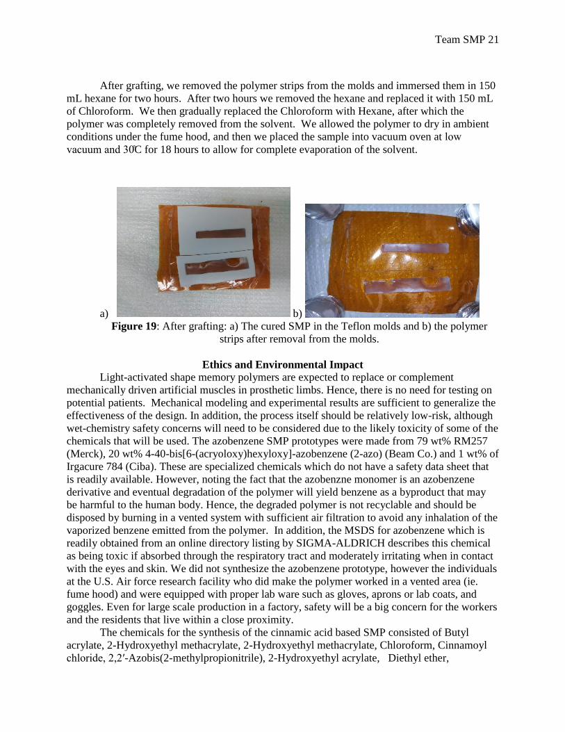
After grafting, we removed the polymer strips from the molds and immersed them in 150
mL hexane for two hours. After two hours we removed the hexane and replaced it with 150 mL
of Chloroform. We then gradually replaced the Chloroform with Hexane, after which the
polymer was completely removed from the solvent. We allowed the polymer to dry in ambient
conditions under the fume hood, and then we placed the sample into vacuum oven at low
vacuum and 30 C for 18 hours to allow for complete evaporation of the solvent.
a) b)
Figure 19: After grafting: a) The cured SMP in the Teflon molds and b) the polymer
strips after removal from the molds.
Ethics and Environmental Impact
Light-activated shape memory polymers are expected to replace or complement
mechanically driven artificial muscles in prosthetic limbs. Hence, there is no need for testing on
potential patients. Mechanical modeling and experimental results are sufficient to generalize the
effectiveness of the design. In addition, the process itself should be relatively low-risk, although
wet-chemistry safety concerns will need to be considered due to the likely toxicity of some of the
chemicals that will be used. The azobenzene SMP prototypes were made from 79 wt% RM257
(Merck), 20 wt% 4-40-bis[6-(acryoloxy)hexyloxy]-azobenzene (2-azo) (Beam Co.) and 1 wt% of
Irgacure 784 (Ciba). These are specialized chemicals which do not have a safety data sheet that
is readily available. However, noting the fact that the azobenzne monomer is an azobenzene
derivative and eventual degradation of the polymer will yield benzene as a byproduct that may
be harmful to the human body. Hence, the degraded polymer is not recyclable and should be
disposed by burning in a vented system with sufficient air filtration to avoid any inhalation of the
vaporized benzene emitted from the polymer. In addition, the MSDS for azobenzene which is
readily obtained from an online directory listing by SIGMA-ALDRICH describes this chemical
as being toxic if absorbed through the respiratory tract and moderately irritating when in contact
with the eyes and skin. We did not synthesize the azobenzene prototype, however the individuals
at the U.S. Air force research facility who did make the polymer worked in a vented area (ie.
fume hood) and were equipped with proper lab ware such as gloves, aprons or lab coats, and
goggles. Even for large scale production in a factory, safety will be a big concern for the workers
and the residents that live within a close proximity.
The chemicals for the synthesis of the cinnamic acid based SMP consisted of Butyl
acrylate, 2-Hydroxyethyl methacrylate, 2-Hydroxyethyl methacrylate, Chloroform, Cinnamoyl
chloride, 2,2′-Azobis(2-methylpropionitrile), 2-Hydroxyethyl acrylate, Diethyl ether,

Team SMP 22
Triethylamine, Toluene, Hydrochloric acid, Sodium sulfate and Hexane. Almost all of these
chemicals are harmful to humans if ingested and often lead to irritation when in contact with the
skin and eyes. Hence, safety and caution must be observed when attempting to synthesize CA
SMPs. The fraction of each chemical used in the synthesis is described latter in the Prototyping
section. The greatest environmental impact associated with the synthesis of CA is the waste
generated during the grafting of the polymer. As indicated in the prototyping section, the grafting
the CA polymer requires that we dissolve the bulk material in a 300 ml of hexane/chloroform
mixture to remove the unreacted monomers. Subsequently, this mixture was exchanged several
times before the polymer was ready to be dried in a vacuum oven. Hence, this process requires
~1 L of both hexane and chloroform and each is designated as waste after the dissolved polymer
is removed. If this is scaled up to a batch process, there needs to be a protocol for dealing with
the large quantity of both hexane and chloroform that will be generated as waste. Our approach
to deal with this issue would be to create a process in which several of the CA SMP are grafted
and dissolved together in the hexane chloroform mixture at a small scale. This process would
still generate waste, but the yield of grafted CA SMP from each batch will be greater in
comparison to a small scale batch process where a single SMP strip is made per graft cycle.
Intellectual Merit
Since the team does not have past experience modeling, especially as needed for these
types of polymer simulations, we expect to gain knowledge and practical experience in this area.
By designing our material based on biological and mechanical parameters from existing
literature, we will gain familiarity with the processes of material selection and design, from
chemical precursors to specifications of size and shape. Upon successful completion of our
project, we will have expanded our knowledge on the shape memory effect for polymeric
materials and their applicability as actuators in arm prostheses. In particular, we will have gained
a well-rounded understanding of the actuation and relaxation mechanisms in azobenzene and
cinnamic acid SMPs and their response under UV and visible irradiation.
To our knowledge, there has been no research into the application of light activated
SMPs for actuation of prosthetic arms. In our efforts to investigate this topic, we will consider
the properties of two types of SMPs that could potentially serve in this type of application,
creating and testing a new design for light-activated arm motion. Subsequently, the material
properties of both azobenzene and cinnamic acid SMPs will be modeled and characterized,
allowing for further research into their adaptation for prosthetic as well as robotic muscular
applications.
Broader Impact
As a medical project, there is a large potential market for applications. Both medical
researchers and patients can be expected to take an interest in this type of research for future
biomedical applications. This specific research will apply to prosthetic arms, but could be
expanded to include other types of prosthetics or even robotics. Furthermore, this technology can
be adapted readily to be used in vivo, for both muscular and cardiovascular applications. The
requirements of the human body have been considered throughout this design process, so it
would be a simple step to adapt this research for use in many other medical applications, such as
those listed in Sokolowski’s work [Sokolowski, et al., 2007]. By solving some of the problems
with traditional shape memory materials, both alloys and polymers, we will make shape memory
materials more feasible for use across a broader spectrum of applications.
Team SMP 23
The arm prosthetic model being proposed yields several advantages over current high-
tech prostheses available in the market. Some of these advantages include simplicity in
component design, significant weight reductions and affordability. Hence, attainment of
successful results for this model would make light-activated SMPs a prominent source for
artificial muscles in biomedical applications. For instance, pneumatic artificial muscles (PAM)
also referred to as McKibben artificial muscles require a constant input of pressurized air in
order to mechanically actuate an arm prosthesis. This design requires integration of a vast
supply of compressed air which makes it difficult to incorporate into a stand-alone prosthesis. In
addition, the conventional metal frame which serves as the central supporting structure for the
PAM will retain a higher density over the proposed polymer-based prostheses design. Clearly, a
successful design of a light-activated SMP artificial muscle will yield a lighter prosthesis that is
both technologically apt and affordable to the average patient.
Currently, the monomers for making azobenzene SMPs are monopolized by a single
entity (BEAM. Co) and the feasibility of direct synthesis is complicated and time consuming.
Thus, the availability of promising results for application in arm prostheses is sure to evoke more
participants in this market and eventually drive costs down. The associated low financial risk
from lower material costs will enable researchers and companies across the world to undertake
more sophisticated analysis on the actuation capabilities of azobenzene SMPs for prostheses.
This analogy was used to deduce the affordability feature that is anticipated with attainment of
successful results for the proposed design.
In addition to macro-scale biomedical applications, fully functional light-activated SMPs
are anticipated to facilitate the development of micro-scale technologies such as sensors and light
triggered switches, micro-pumps, molecular shuttles and rotors, as well as optical data storage
devices [Cembran, et al., 2004; Shao, et al., 2008].
Results and Discussion
Schematic model and calculation results for SMP sheet design
The dimensions for the elbow circumference, bicep circumference, wrist circumference
and the length of each anatomical segment are given in Table I. As mentioned in the “Design of
SMP Sheets” section, these values were obtained from a study performed by .F. Chandler. This
study utilized random sampling to generate an estimate of the dimensions and weights for all of
the human extremities. The values reported in Table I are only the averages and exclude reported
variances. In addition, the mean of the left and right segments of the arm components is used as a
basis to compute an estimate of the arm volume.
Table II provides the volume, mass and weight of the upper arm, forearm and hand. Prior
to calculating the volume of the tapered cylinder segments that approximate the arm, it was
necessary to convert the circumferences ( ) given in Table I to radius ( ) values. This was
performed using the following equation,
=
(9)
where the constant π ≈ 3.1 16. The value of the variable , which represented the difference
between tapered cylinder and cone length in equation (1) and equation (2), was set to 1 to
simplify the calculation. In addition, the upper arm length intersecting the bicep circumference
was estimated as half of the mean upper arm length reported in Table I.

Team SMP 24
Elbow Bicep Wrist Hand
Radius (cm) 4.56 4.78 2.72 3.38
In order to calculate the weight of each arm segment using equation (3), we need to know
the density of polypropylene ( ). This value is aproximated as 0.902 g/cc based on the density
of extrusion-grade polypropylene [Matweb].
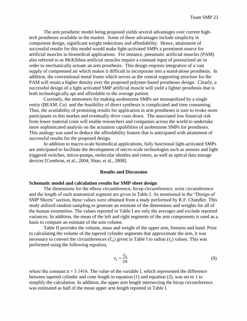
The schematic diagram in Figure 20 outlines the dimensions associated with a model for
a polypropylene-based prosthetic arm. In this 2D drawing, the dimension of the connection
between the upper arm and forearm is the elbow radius. Similarly, the dimension of the
connection between the forearm and the hand is the wrist radius.
Superficial Anatomy Left (cm) Right (cm) Average (cm)
Elbow Circ 28.18 29.13 28.66
Acromial-Radiale 33.67 33.28 33.48
Biceps Circ 29.92 30.13 30.03
Radiale-stylion 25.93 33.28 29.61
Wrist Circ 16.98 17.15 17.07
Stylion-(Neta, Meta) 8.05 8.33 8.19
Hand Circ 21.12 21.38 21.25
volume (cm3) Mass (kg) Weight (N)
Upper Arm 150.44 0.14 1.33
Forearm 255.64 0.23 2.26
Hand 50.83 0.05 0.45
Table I: Dimension estimates for arm components [25]
Table II: Calculated estimates of volume, mass and weight of arm segments
Table III: Calculated radius estimates for elbow, bicep, wrist and hand
Team SMP 25
Figure 20: Dimensions of a prosthetic arm model
The weights for the forearm and hand are located at the center of mass. Initially, this position
was assumed to be the midpoint for each segment of the arm. However, this approximation is
incorrect since the distribution of mass in the tapered cylindrical geometry varies along the
segment length. The location of the center of mass is calculated by the following equation
[Hibbeler, 2010],
(10)
where the variables , and correspond to the position of a mass element , in the segment,
relative to a specified origin. Since the polypropylene prosthesis model shown in Figure 2 retains
a uniform/constant density, equation (10) is further simplified to an equation for the centroid (c)
of a volume through the relation . The resulting expressions for the centroid of a
volume are given by the following equations [Hibbeler, 2010],
. (11)
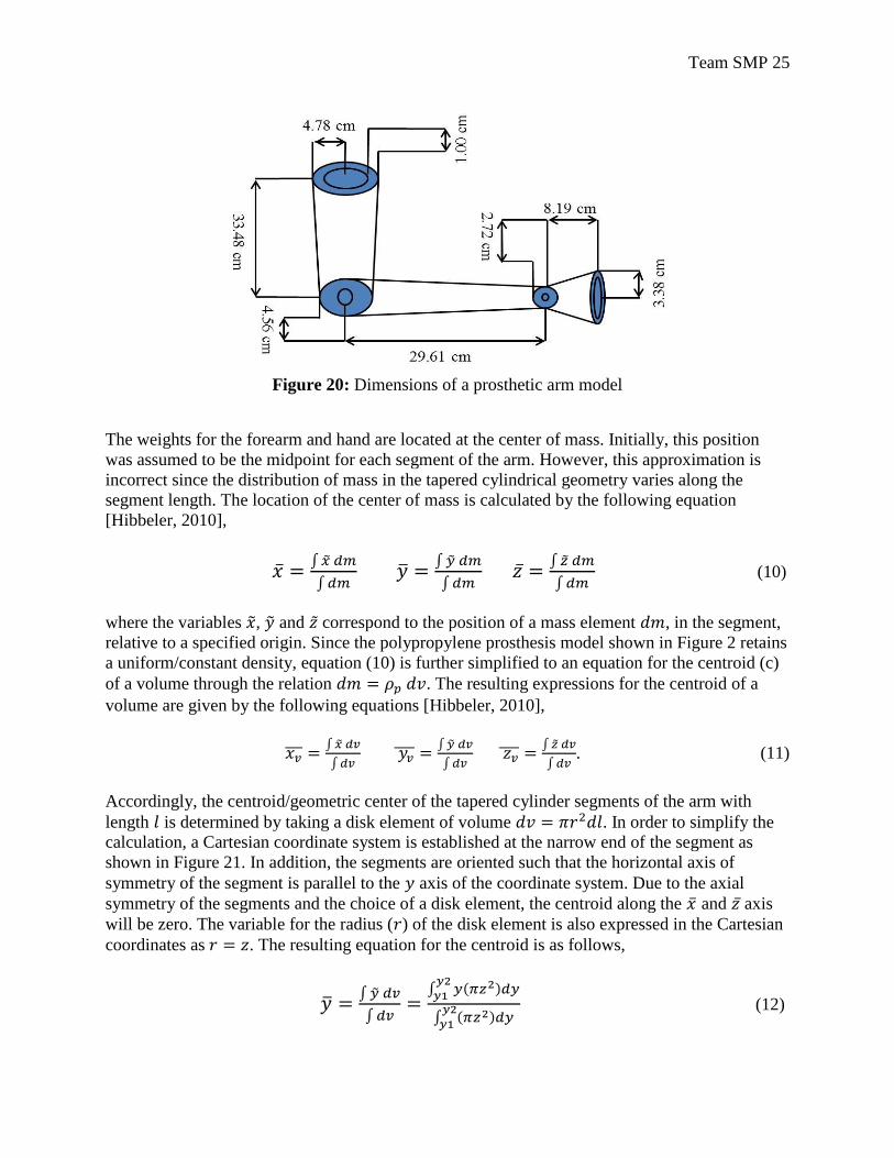
Accordingly, the centroid/geometric center of the tapered cylinder segments of the arm with
length is determined by taking a disk element of volume . In order to simplify the
calculation, a Cartesian coordinate system is established at the narrow end of the segment as
shown in Figure 21. In addition, the segments are oriented such that the horizontal axis of
symmetry of the segment is parallel to the axis of the coordinate system. Due to the axial
symmetry of the segments and the choice of a disk element, the centroid along the and axis
will be zero. The variable for the radius ( ) of the disk element is also expressed in the Cartesian
coordinates as . The resulting equation for the centroid is as follows,
(12)
Team SMP 26
where is substituted for the element length , and the limits of integration and define
the boundaries of the total segment length along the axis.
Figure 21: Visual representation of a disc element in a conical segment [30]
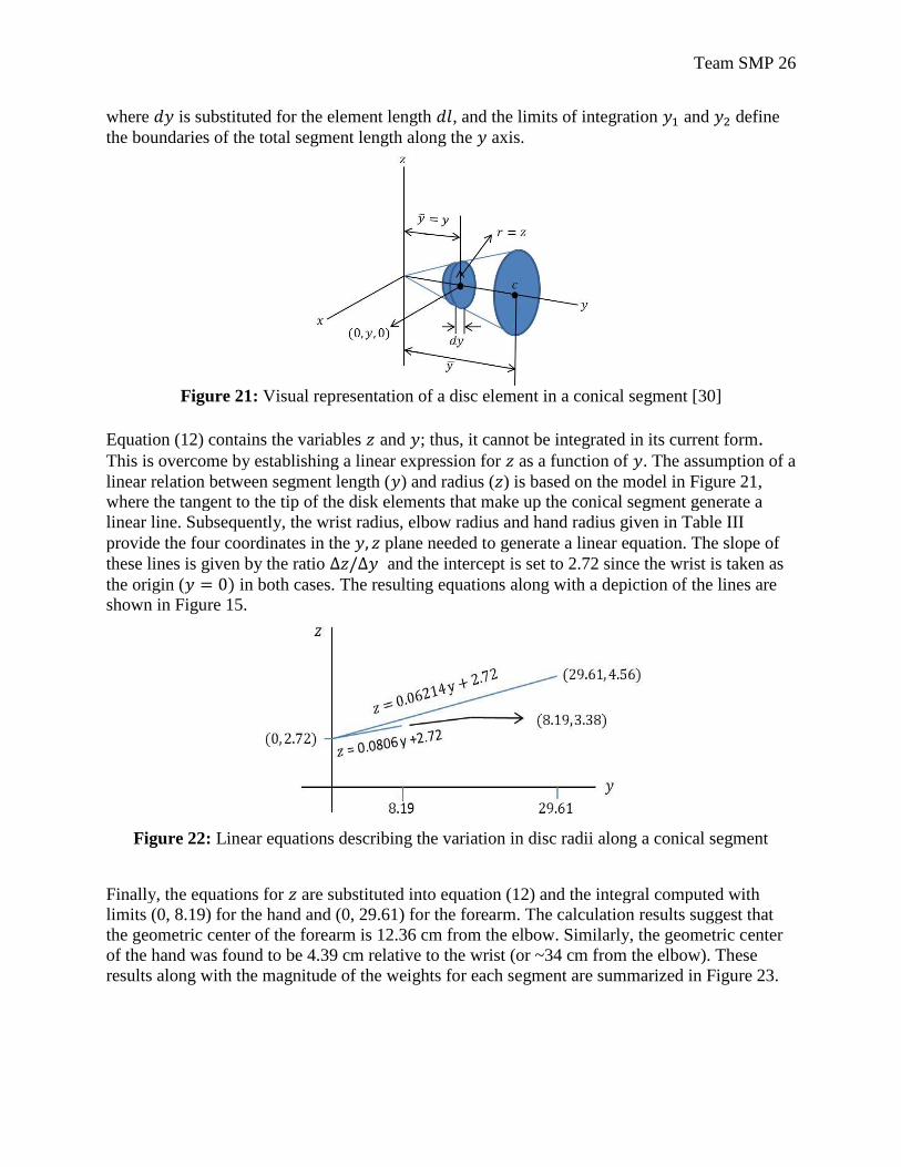
Equation (12) contains the variables and ; thus, it cannot be integrated in its current form. This is overcome by establishing a linear expression for as a function of . The assumption of a
linear relation between segment length ( ) and radius ( ) is based on the model in Figure 21,
where the tangent to the tip of the disk elements that make up the conical segment generate a
linear line. Subsequently, the wrist radius, elbow radius and hand radius given in Table III
provide the four coordinates in the plane needed to generate a linear equation. The slope of
these lines is given by the ratio and the intercept is set to 2.72 since the wrist is taken as
the origin ( in both cases. The resulting equations along with a depiction of the lines are
shown in Figure 15.
Figure 22: Linear equations describing the variation in disc radii along a conical segment
Finally, the equations for are substituted into equation (12) and the integral computed with
limits (0, 8.19) for the hand and (0, 29.61) for the forearm. The calculation results suggest that
the geometric center of the forearm is 12.36 cm from the elbow. Similarly, the geometric center
of the hand was found to be 4.39 cm relative to the wrist (or ~34 cm from the elbow). These
results along with the magnitude of the weights for each segment are summarized in Figure 23.
Team SMP 27
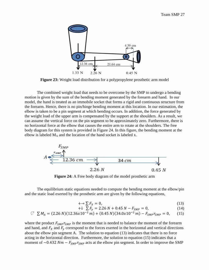
Figure 23: Weight load distribution for a polypropylene prosthetic arm model
The combined weight load that needs to be overcome by the SMP to undergo a bending
motion is given by the sum of the bending moment generated by the forearm and hand. In our
model, the hand is treated as an immobile socket that forms a rigid and continuous structure from
the forearm. Hence, there is no pin/hinge bending moment at this location. In our estimation, the
elbow is taken to be a pin segment at which bending occurs. In addition, the force generated by
the weight load of the upper arm is compensated by the support at the shoulders. As a result, we
can assume the vertical force on the pin segment to be approximately zero. Furthermore, there is
no horizontal force at the elbow that causes the entire arm to rotate at the shoulders. The free
body diagram for this system is provided in Figure 24. In this figure, the bending moment at the
elbow is labeled MA and the location of the hand socket is labeled x.
Figure 24: A Free body diagram of the model prosthetic arm
The equilibrium static equations needed to compute the bending moment at the elbow/pin
and the static load exerted by the prosthetic arm are given by the following equations,
, (13)
, (14)
, (15)
where the product is the moment that is needed to balance the moment of the forearm
and hand, and and correspond to the forces exerted in the horizontal and vertical directions
about the elbow pin segment A. The solution to equation (13) indicates that there is no force
acting in the horizontal direction. Furthermore, the solution to equation (15) indicates that a
moment of acts at the elbow pin segment. In order to improve the SMP
Team SMP 28
sheet design, we optimized the length ( ) in equation (15) by creating a prosthesis model and
used equation (15) to obtain the force that will balance the bending moment of the forearm and
hand.
Prosthetic arm and SMP sheet Model
In the design of SMP sheets section it was mentioned that Autodesk Inventor would be
used to create a 3D model of the polypropylene prosthetic arm. This model retains the
dimensions provided by Chandler et al. (Table I) and a pin system that connects the forearm to
the upper arm segment. Furthermore, our design aimed to create an assembly of several SMP
sheets/strips instead of a single strip. Hence, it was necessary to reduce the circular elbow
circumference into a semicircle on which the SMP sheet can be mounted. The design of the pin
system, which rests on this semicircle, required that we perform an optimization problem
consisting of the maximum rectangular area that could fit in a semicircle. The optimization
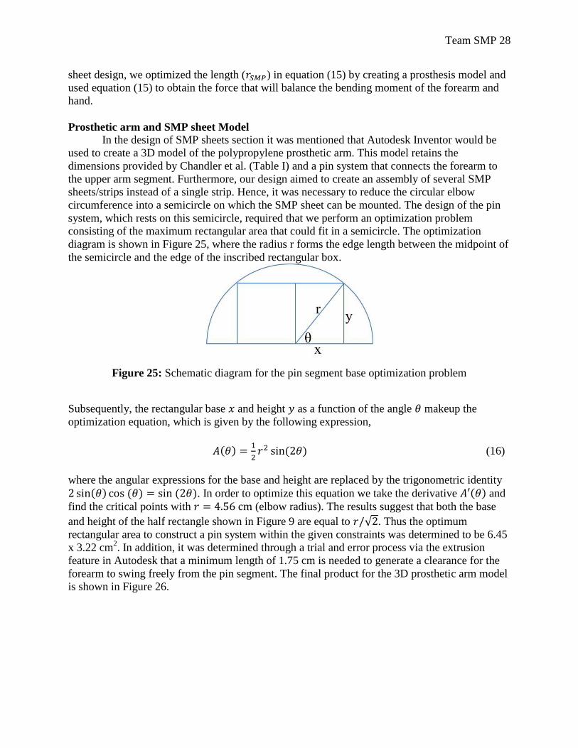
diagram is shown in Figure 25, where the radius r forms the edge length between the midpoint of
the semicircle and the edge of the inscribed rectangular box.
Figure 25: Schematic diagram for the pin segment base optimization problem
Subsequently, the rectangular base and height as a function of the angle makeup the
optimization equation, which is given by the following expression,
(16)
where the angular expressions for the base and height are replaced by the trigonometric identity
. In order to optimize this equation we take the derivative and
find the critical points with (elbow radius). The results suggest that both the base
and height of the half rectangle shown in Figure 9 are equal to . Thus the optimum
rectangular area to construct a pin system within the given constraints was determined to be 6.45
x 3.22 cm2. In addition, it was determined through a trial and error process via the extrusion
feature in Autodesk that a minimum length of 1.75 cm is needed to generate a clearance for the
forearm to swing freely from the pin segment. The final product for the 3D prosthetic arm model
is shown in Figure 26.
Team SMP 29
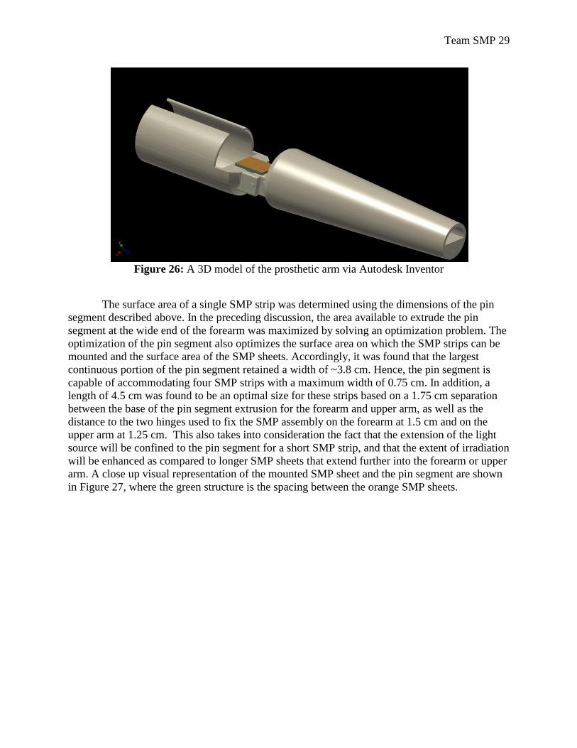
Figure 26: A 3D model of the prosthetic arm via Autodesk Inventor
The surface area of a single SMP strip was determined using the dimensions of the pin
segment described above. In the preceding discussion, the area available to extrude the pin
segment at the wide end of the forearm was maximized by solving an optimization problem. The
optimization of the pin segment also optimizes the surface area on which the SMP strips can be
mounted and the surface area of the SMP sheets. Accordingly, it was found that the largest
continuous portion of the pin segment retained a width of ~3.8 cm. Hence, the pin segment is
capable of accommodating four SMP strips with a maximum width of 0.75 cm. In addition, a
length of 4.5 cm was found to be an optimal size for these strips based on a 1.75 cm separation
between the base of the pin segment extrusion for the forearm and upper arm, as well as the
distance to the two hinges used to fix the SMP assembly on the forearm at 1.5 cm and on the
upper arm at 1.25 cm. This also takes into consideration the fact that the extension of the light
source will be confined to the pin segment for a short SMP strip, and that the extent of irradiation
will be enhanced as compared to longer SMP sheets that extend further into the forearm or upper
arm. A close up visual representation of the mounted SMP sheet and the pin segment are shown
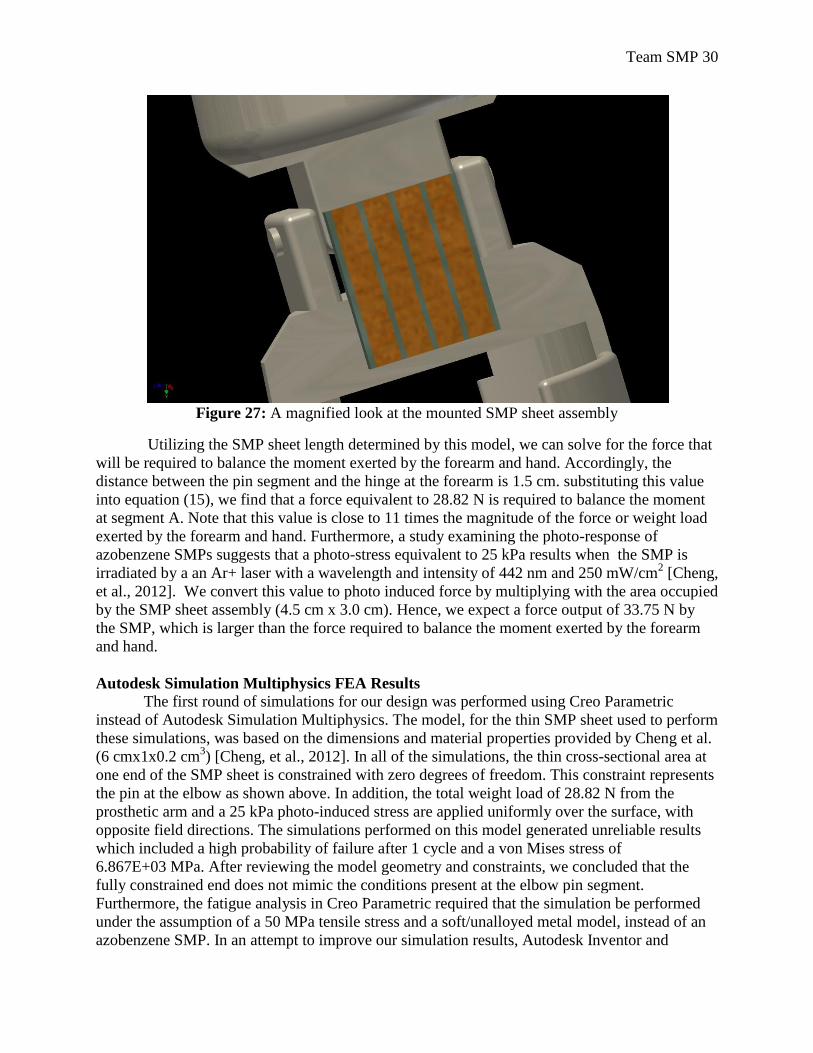
in Figure 27, where the green structure is the spacing between the orange SMP sheets.
Team SMP 30
Figure 27: A magnified look at the mounted SMP sheet assembly
Utilizing the SMP sheet length determined by this model, we can solve for the force that
will be required to balance the moment exerted by the forearm and hand. Accordingly, the
distance between the pin segment and the hinge at the forearm is 1.5 cm. substituting this value
into equation (15), we find that a force equivalent to 28.82 N is required to balance the moment
at segment A. Note that this value is close to 11 times the magnitude of the force or weight load
exerted by the forearm and hand. Furthermore, a study examining the photo-response of
azobenzene SMPs suggests that a photo-stress equivalent to 25 kPa results when the SMP is
irradiated by a an Ar+ laser with a wavelength and intensity of 442 nm and 250 mW/cm2 [Cheng,
et al., 2012]. We convert this value to photo induced force by multiplying with the area occupied
by the SMP sheet assembly (4.5 cm x 3.0 cm). Hence, we expect a force output of 33.75 N by
the SMP, which is larger than the force required to balance the moment exerted by the forearm
and hand.
Autodesk Simulation Multiphysics FEA Results
The first round of simulations for our design was performed using Creo Parametric
instead of Autodesk Simulation Multiphysics. The model, for the thin SMP sheet used to perform
these simulations, was based on the dimensions and material properties provided by Cheng et al.
(6 cmx1x0.2 cm3) [Cheng, et al., 2012]. In all of the simulations, the thin cross-sectional area at
one end of the SMP sheet is constrained with zero degrees of freedom. This constraint represents
the pin at the elbow as shown above. In addition, the total weight load of 28.82 N from the
prosthetic arm and a 25 kPa photo-induced stress are applied uniformly over the surface, with
opposite field directions. The simulations performed on this model generated unreliable results
which included a high probability of failure after 1 cycle and a von Mises stress of
6.867E+03 MPa. After reviewing the model geometry and constraints, we concluded that the
fully constrained end does not mimic the conditions present at the elbow pin segment.
Furthermore, the fatigue analysis in Creo Parametric required that the simulation be performed
under the assumption of a 50 MPa tensile stress and a soft/unalloyed metal model, instead of an
azobenzene SMP. In an attempt to improve our simulation results, Autodesk Inventor and
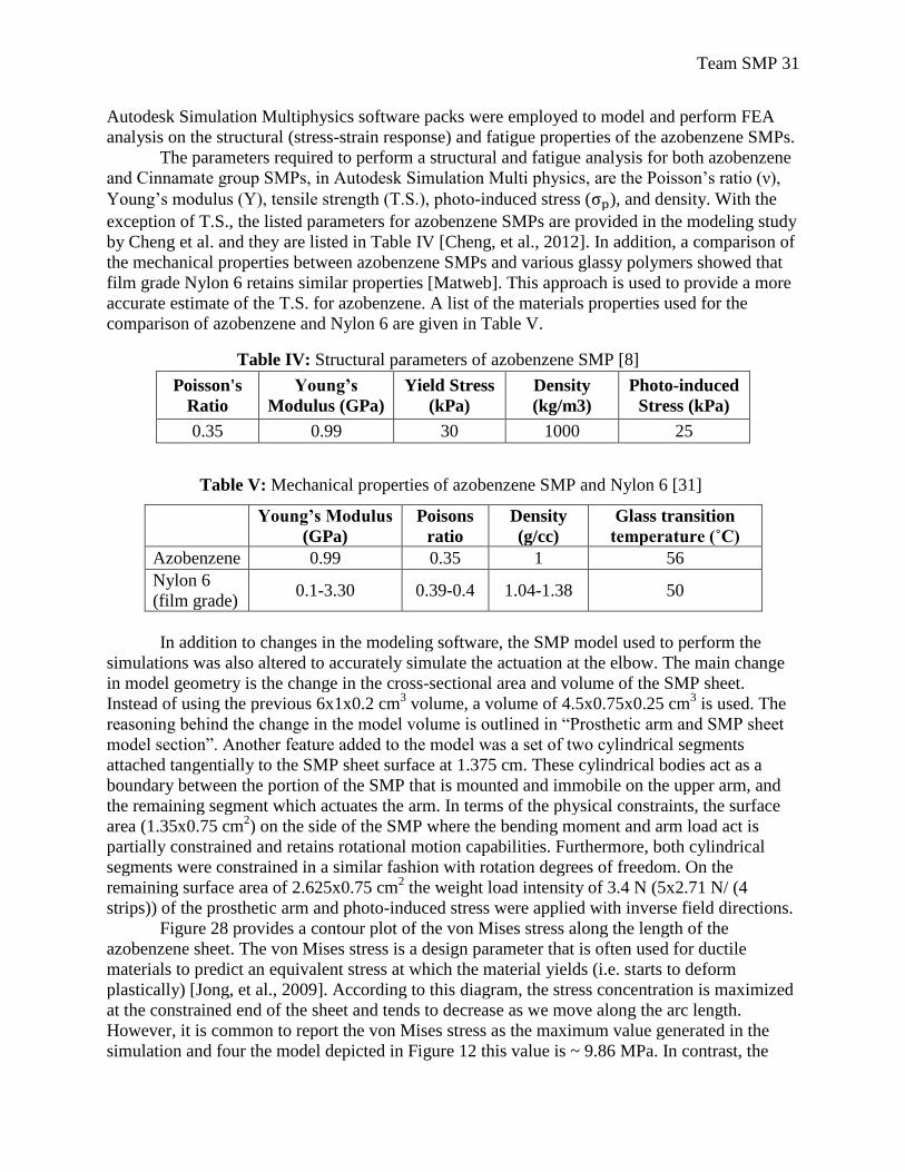
Team SMP 31
Autodesk Simulation Multiphysics software packs were employed to model and perform FEA
analysis on the structural (stress-strain response) and fatigue properties of the azobenzene SMPs.
The parameters required to perform a structural and fatigue analysis for both azobenzene
and Cinnamate group SMPs, in Autodesk Simulation Multi physics, are the Poisson’s ratio (ν),
Young’s modulus (Y), tensile strength (T.S.), photo-induced stress ( ), and density. With the
exception of T.S., the listed parameters for azobenzene SMPs are provided in the modeling study
by Cheng et al. and they are listed in Table IV [Cheng, et al., 2012]. In addition, a comparison of
the mechanical properties between azobenzene SMPs and various glassy polymers showed that
film grade Nylon 6 retains similar properties [Matweb]. This approach is used to provide a more
accurate estimate of the T.S. for azobenzene. A list of the materials properties used for the
comparison of azobenzene and Nylon 6 are given in Table V.
Poisson's
Ratio
Young’s
Modulus (GPa)
Yield Stress
(kPa)
Density
(kg/m3)
Photo-induced
Stress (kPa)
0.35 0.99 30 1000 25
Young’s Modulus
(GPa)
Poisons
ratio
Density
(g/cc)
Glass transition
temperature (˚C)
Azobenzene 0.99 0.35 1 56
Nylon 6
(film grade) 0.1-3.30 0.39-0.4 1.04-1.38 50
In addition to changes in the modeling software, the SMP model used to perform the
simulations was also altered to accurately simulate the actuation at the elbow. The main change
in model geometry is the change in the cross-sectional area and volume of the SMP sheet.
Instead of using the previous 6x1x0.2 cm3 volume, a volume of 4.5x0.75x0.25 cm
3 is used. The
reasoning behind the change in the model volume is outlined in “Prosthetic arm and SMP sheet
model section”. Another feature added to the model was a set of two cylindrical segments
attached tangentially to the SMP sheet surface at 1.375 cm. These cylindrical bodies act as a
boundary between the portion of the SMP that is mounted and immobile on the upper arm, and
the remaining segment which actuates the arm. In terms of the physical constraints, the surface
area (1.35x0.75 cm2) on the side of the SMP where the bending moment and arm load act is
partially constrained and retains rotational motion capabilities. Furthermore, both cylindrical
segments were constrained in a similar fashion with rotation degrees of freedom. On the
remaining surface area of 2.625x0.75 cm2 the weight load intensity of 3.4 N (5x2.71 N/ (4
strips)) of the prosthetic arm and photo-induced stress were applied with inverse field directions.
Figure 28 provides a contour plot of the von Mises stress along the length of the
azobenzene sheet. The von Mises stress is a design parameter that is often used for ductile
materials to predict an equivalent stress at which the material yields (i.e. starts to deform
plastically) [Jong, et al., 2009]. According to this diagram, the stress concentration is maximized
at the constrained end of the sheet and tends to decrease as we move along the arc length.
However, it is common to report the von Mises stress as the maximum value generated in the
simulation and four the model depicted in Figure 12 this value is ~ 9.86 MPa. In contrast, the
Table IV: Structural parameters of azobenzene SMP [8]
Table V: Mechanical properties of azobenzene SMP and Nylon 6 [31]
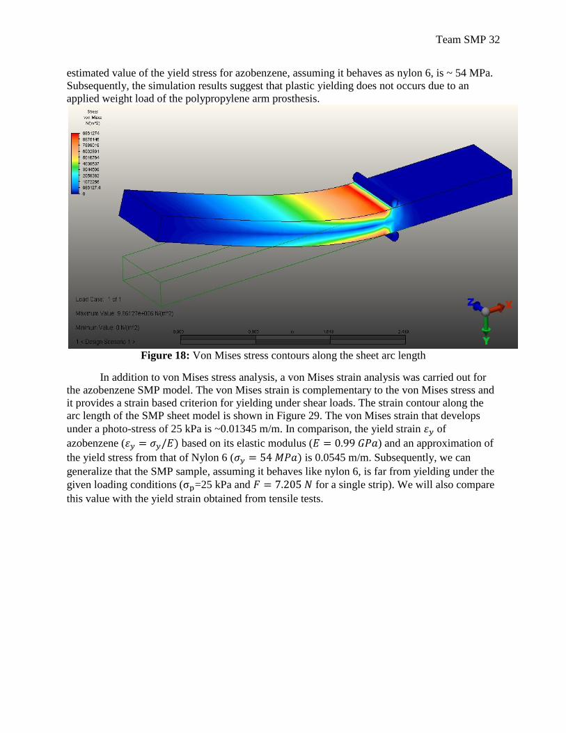
Team SMP 32
estimated value of the yield stress for azobenzene, assuming it behaves as nylon 6, is ~ 54 MPa.
Subsequently, the simulation results suggest that plastic yielding does not occurs due to an
applied weight load of the polypropylene arm prosthesis.
Figure 18: Von Mises stress contours along the sheet arc length
In addition to von Mises stress analysis, a von Mises strain analysis was carried out for
the azobenzene SMP model. The von Mises strain is complementary to the von Mises stress and
it provides a strain based criterion for yielding under shear loads. The strain contour along the
arc length of the SMP sheet model is shown in Figure 29. The von Mises strain that develops
under a photo-stress of 25 kPa is ~0.01345 m/m. In comparison, the yield strain of
azobenzene ( based on its elastic modulus ( ) and an approximation of
the yield stress from that of Nylon 6 ( is 0.0545 m/m. Subsequently, we can
generalize that the SMP sample, assuming it behaves like nylon 6, is far from yielding under the
given loading conditions ( =25 kPa and for a single strip). We will also compare
this value with the yield strain obtained from tensile tests.
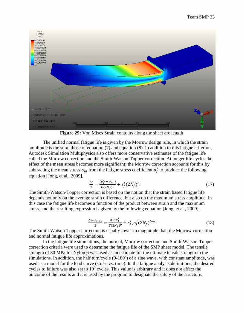
Team SMP 33
Figure 29: Von Mises Strain contours along the sheet arc length
The unified normal fatigue life is given by the Morrow design rule, in which the strain
amplitude is the sum, those of equation (7) and equation (8). In addition to this fatigue criterion,
Autodesk Simulation Multiphysics also offers more conservative estimates of the fatigue life
called the Morrow correction and the Smith-Watson-Topper correction. At longer life cycles the
effect of the mean stress becomes more significant; the Morrow correction accounts for this by
subtracting the mean stress from the fatigue stress coefficient to produce the following
equation [Jong, et al., 2009],
. (17)
The Smith-Watson-Topper correction is based on the notion that the strain based fatigue life
depends not only on the average strain difference, but also on the maximum stress amplitude. In
this case the fatigue life becomes a function of the product between strain and the maximum
stress, and the resulting expression is given by the following equation [Jong, et al., 2009],
. (18)
The Smith-Watson-Topper correction is usually lower in magnitude than the Morrow correction
and normal fatigue life approximations.
In the fatigue life simulations, the normal, Morrow correction and Smith-Watson-Topper
correction criteria were used to determine the fatigue life of the SMP sheet model. The tensile
strength of 80 MPa for Nylon 6 was used as an estimate for the ultimate tensile strength in the
simulations. In addition, the half turn/cycle (0-180˚) of a sine wave, with constant amplitude, was
used as a model for the load curve (stress vs. time). In the fatigue analysis definitions, the desired
cycles to failure was also set to 105 cycles. This value is arbitrary and it does not affect the
outcome of the results and it is used by the program to designate the safety of the structure.
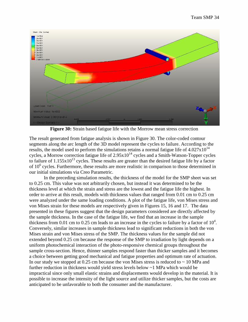
Team SMP 34
Figure 30: Strain based fatigue life with the Morrow mean stress correction
The result generated from fatigue analysis is shown in Figure 30. The color-coded contour
segments along the arc length of the 3D model represent the cycles to failure. According to the
results, the model used to perform the simulations retains a normal fatigue life of 4.027x10¹⁴
cycles, a Morrow correction fatigue life of 2.95x10¹⁴
cycles and a Smith-Watson-Topper cycles
to failure of 1.155x10¹³
cycles. These results are greater than the desired fatigue life by a factor
of 106 cycles. Furthermore, these results are more realistic in comparison to those determined in
our initial simulations via Creo Parametric.
In the preceding simulation results, the thickness of the model for the SMP sheet was set
to 0.25 cm. This value was not arbitrarily chosen, but instead it was determined to be the
thickness level at which the strain and stress are the lowest and the fatigue life the highest. In
order to arrive at this result, models with thickness values that ranged from 0.01 cm to 0.25 cm
were analyzed under the same loading conditions. A plot of the fatigue life, von Mises stress and
von Mises strain for these models are respectively given in Figures 15, 16 and 17. The data
presented in these figures suggest that the design parameters considered are directly affected by
the sample thickness. In the case of the fatigue life, we find that an increase in the sample
thickness from 0.01 cm to 0.25 cm leads to an increase in the cycles to failure by a factor of 104.
Conversely, similar increases in sample thickness lead to significant reductions in both the von
Mises strain and von Mises stress of the SMP. The thickness values for the sample did not
extended beyond 0.25 cm because the response of the SMP to irradiation by light depends on a
uniform photochemical interaction of the photo-responsive chemical groups throughout the
sample cross-section. Hence, thinner samples respond faster than thicker samples and it becomes
a choice between getting good mechanical and fatigue properties and optimum rate of actuation.
In our study we stopped at 0.25 cm because the von Mises stress is reduced to ~ 10 MPa and
further reduction in thickness would yield stress levels below ~1 MPa which would be
impractical since only small elastic strains and displacements would develop in the material. It is
possible to increase the intensity of the light source and utilize thicker samples, but the costs are
anticipated to be unfavorable to both the consumer and the manufacturer.
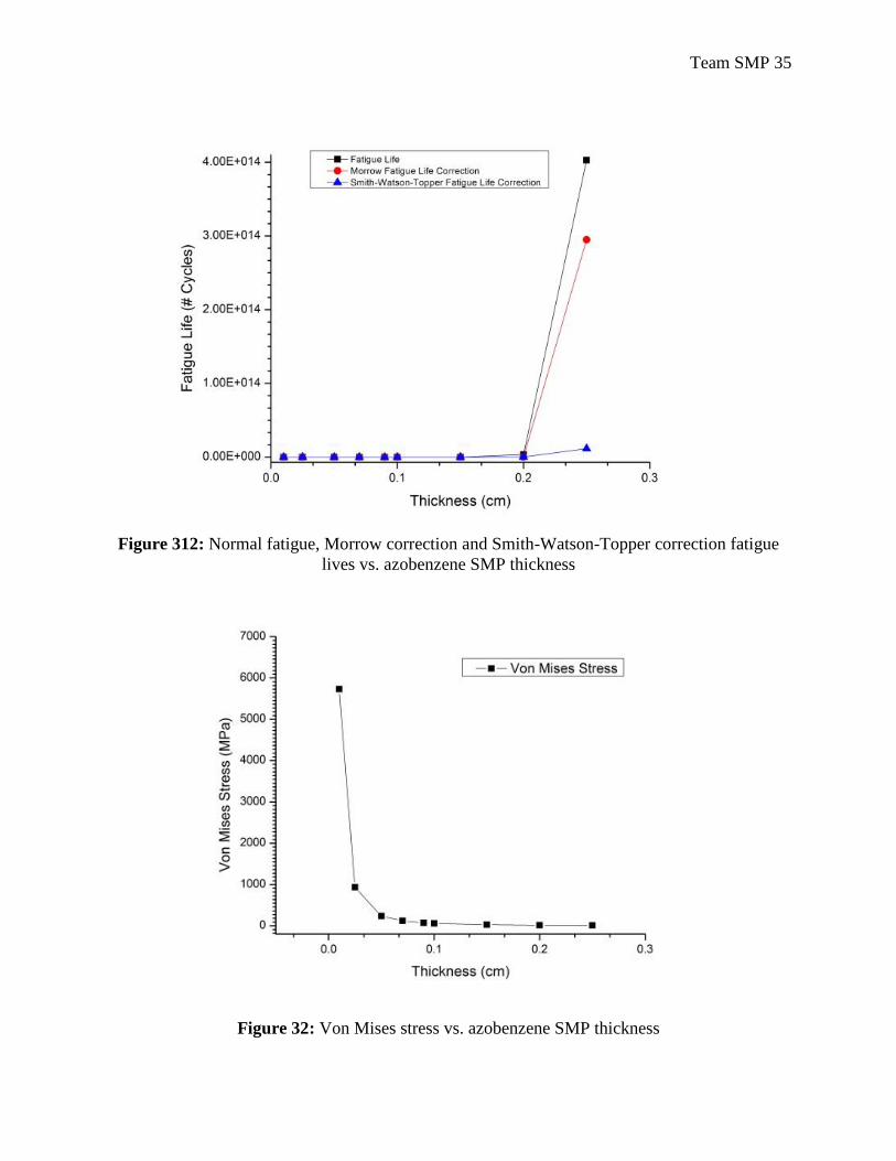
Team SMP 35
Figure 312: Normal fatigue, Morrow correction and Smith-Watson-Topper correction fatigue
lives vs. azobenzene SMP thickness
Figure 32: Von Mises stress vs. azobenzene SMP thickness
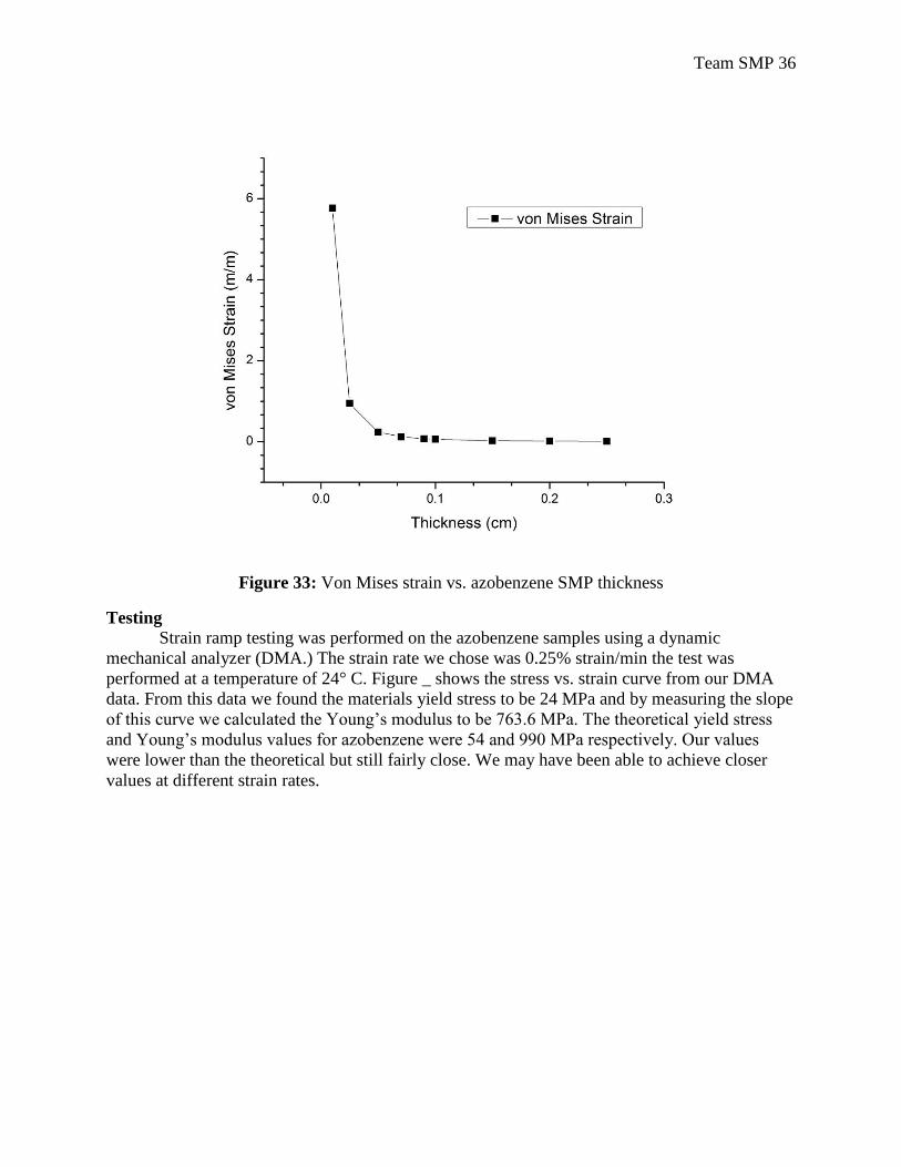
Team SMP 36
Figure 33: Von Mises strain vs. azobenzene SMP thickness
Testing
Strain ramp testing was performed on the azobenzene samples using a dynamic
mechanical analyzer (DMA.) The strain rate we chose was 0.25% strain/min the test was
performed at a temperature of 24° C. Figure _ shows the stress vs. strain curve from our DMA
data. From this data we found the materials yield stress to be 24 MPa and by measuring the slope
of this curve we calculated the Young’s modulus to be 763.6 MPa. The theoretical yield stress
and Young’s modulus values for azobenzene were 5 and 990 MPa respectively. Our values
were lower than the theoretical but still fairly close. We may have been able to achieve closer
values at different strain rates.
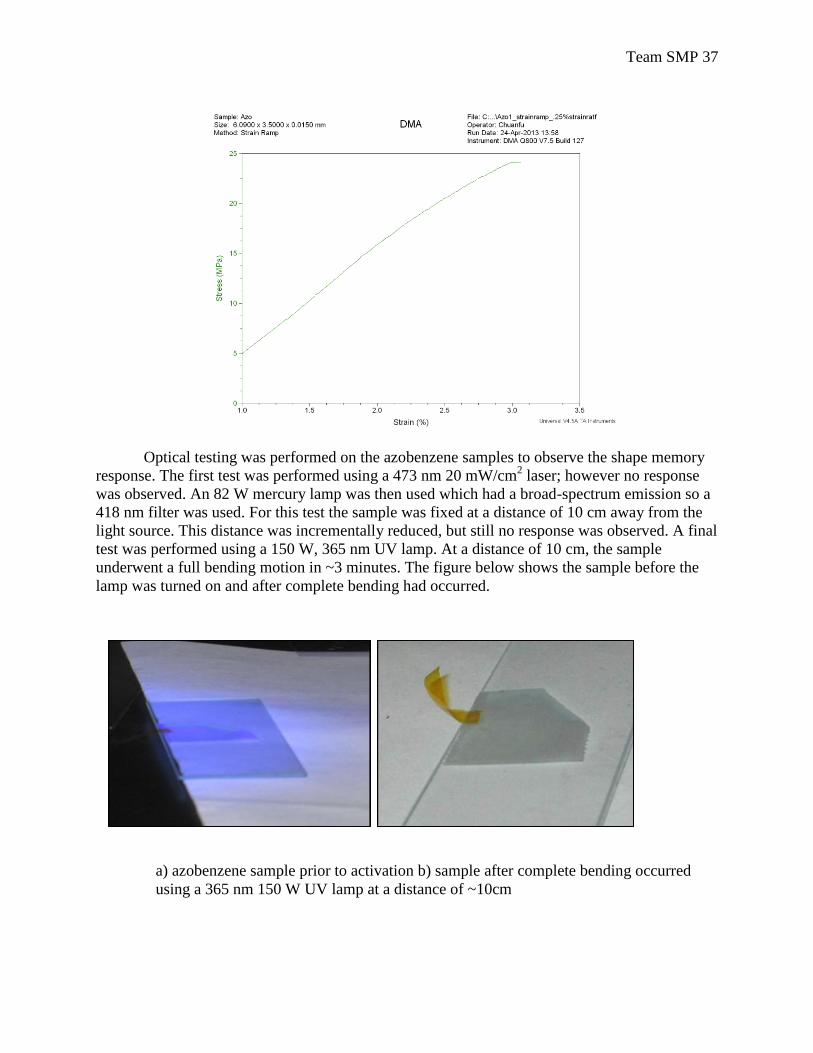
Team SMP 37
Optical testing was performed on the azobenzene samples to observe the shape memory
response. The first test was performed using a 473 nm 20 mW/cm2 laser; however no response
was observed. An 82 W mercury lamp was then used which had a broad-spectrum emission so a
418 nm filter was used. For this test the sample was fixed at a distance of 10 cm away from the
light source. This distance was incrementally reduced, but still no response was observed. A final
test was performed using a 150 W, 365 nm UV lamp. At a distance of 10 cm, the sample
underwent a full bending motion in ~3 minutes. The figure below shows the sample before the
lamp was turned on and after complete bending had occurred.
a) azobenzene sample prior to activation b) sample after complete bending occurred
using a 365 nm 150 W UV lamp at a distance of ~10cm
a)
Team SMP 38
Quantum Yield = (atoms undergoing trans to cis)/(photons absorbed) = .25
When transformation occurs molecule length goes from 9 Å to 5.5 Å.
Using the strain equation:
and using our modeled Von Mises strain of 0.01344719 m/m and our sample length of 4.5 cm we
solve for Δl
to get a value of 0.06053 cm which is our change in sample length after the transition has taken
place. Then dividing this number by the extension per molecule
of 3.5 x 10^-8 cm we find that 1729286 azobenzene molecules required for our modeled required
Von Mises strain. Then to calculate the thickness that contains this number of molecules we use
the equation:
where ρ is density, A is area, t is thickness, Na is avogadros number, and MM is molar mass.
Using this we solve for thickness using 1729286 molecules, a density of 1.09 g/cm^3, an area of
4.5 cm x 0.25 cm, molecular weight of 182.22 g/mol, we find the thickness to be 1.433 x 10^-16
cm. This is the penetration required to activate the needed molecules for activation.
The power ( ) required to actuate the azobenzene SMPs was determined using results
from mechanical simulations and material properties found in literature for the cis (Z) and trans
(E) azobenzene conformers. Accordingly, we used our simulation results for the von Mises strain
( ) and a linear strain relationship given by the equation,
to obtain the elongation, , for a single SMP strip with . Subsequently, this
calculation yields an estimated elongation of 0.0605 cm. The next step in our calculations was to
determine the contraction of a single azobenzene molecule as it transitions from the E → Z
conformer. According to Jiang et al., this value is approximately 3.5 Å/Azo. Molecule [15].
However, within the SMP each light receptive azobenzene molecule is covalently bonded to the
polymer molecular chain. This will counter (or reduce) the contraction of the azobenzene
molecule. To our knowledge, there are no previous studies that investigated the reduction in the
contraction of azobenzene molecules bonded to a polymeric chain. Hence, we will assume a 50%
reduction in the contraction of the azobenzene molecule due to interaction effects. Subsequently,
the reduced contraction length is ~ 1.75 Å/Azo. molecule. We then divide the sample elongation
( ) by this value to obtain the number of azobenzene molecules that need to be
Team SMP 39
activated to induce the required change in length. The calculations indicate that approximately
3.457e+006 Azo. molecules must undergo a E → Z conformation change to elongate the SMP by
0.0605 cm. Since the SMP recovers elastically (i.e. full recovery of deformed shape) the
relaxation from Z → E is assumed to occur by extension of an equivalent number of azobenzene
molecules by ~ 1.8 Å.
The power required to activate ~ 3.457e+006 azobenzene molecules is determined using
the quantum yield values for the E → Z and Z → E conformation changes. According to
Cembran et al. the quantum yield corresponding to the number of molecules that undergo a
change conformation from either E → Z per photons absorbed is 0.25 (i.e. one conformational
change per four photons absorbed). Similarly, the quantum yield for the Z → E conformation
change is ~ 0.53. We obtain the number of photons that must be absorbed in order to induce
either conformational change by taking the ratio of the number of azobenzene molecules
determined above (3.457e+006) and the quantum yield. Our calculations suggest that 1.38e+007
photons must be absorbed in order to induce the E → Z transition and 6.52e+006 photons need
to be absorbed in order to induce a Z → E transition. Assuming a collimated light source, we
can obtain the value for the absorbed power ( ) by dividing the number of photons with the SMP
strip surface area (4.5 x 0.75 cm2). Subsequently, the power needed to cause the E → Z transition
is 4.09e+006 photons∙cm-2
for the E → Z transition and a power of 1.93e+006 photons∙cm-2
is
required to induce the Z → E transition.
The preceding calculations provide only the attenuated light at a specific depth within the
SMP sample. In order to determine the actual power ( ) that must be supplied by a light source,
we will use the Beer-Lambert law which is given by the following expression,
where is the molar absorptivity, C is the molar concentration and is the pathlength of the light
beam. Based on the work by Marino et al., the molar absorptivity for the E and Z state are
respectively ~ 2.5e+004 M-1
cm-1
and ~1.5e+003 M-1
cm-1
. Since the unit M (molarity), for the
absorptivity values, is in moles per litter we multiply by 1000 to convert to cm3. The unknowns
in the Beer-Lambert equation are the path length, concentration and initial intensity . In our
calculations we can specify the path length and determine the concentration using the chemical
properties of azobenzene. In our estimations, we assume that the power attenuates to from
after traveling a path length ( ) equivalent to one micron. A standard concentration for
azobenzene is determined by dividing the density (1.09 g/cm3) with the molecular mass (182.22
g/mol). This yields a standard concentration of 5.98e-003 mol/cm3. We then obtain the value for
by substituting the estimated path length of 1 µm and 5.98e-003 mol/cm3 standard molar
concentration along with the molar absorptivities for the E and Z conformations in the equation
above. The results indicate that light sources with a power equivalent to 3.65e+021 photons∙cm-2
and 1.72e+0021 photons∙cm-2
are required to activate the E → Z and Z → E conformations
respectively.
Reliability of simulation results and test cases
As mentioned above, the proposed arm prosthesis design utilizes dimensions for an
average human arm and polypropylene as the base material. Hence, the magnitude of the weights
for the forearm and hand used in the static equilibrium calculations render realistic
approximations. However, literature based theoretical values for the elastic modulus and poisons
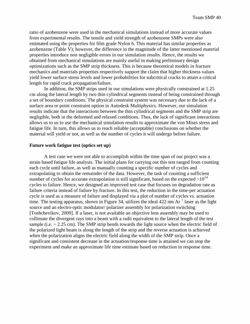
Team SMP 40
ratio of azobenzene were used in the mechanical simulations instead of more accurate values
from experimental results. The tensile and yield strength of azobenzene SMPs were also
estimated using the properties for film grade Nylon 6. This material has similar properties as
azobenzene (Table V); however, the difference in the magnitude of the latter mentioned material
properties introduce non negligible errors in our simulation results. Hence, the results we
obtained from mechanical simulations are mainly useful in making preliminary design
optimizations such as the SMP strip thickness. This is because theoretical models in fracture
mechanics and materials properties respectively support the claim that higher thickness values
yield lower surface stress levels and lower probabilities for subcritical cracks to attain a critical
length for rapid crack propagation/failure.
In addition, the SMP strips used in our simulations were physically constrained at 1.25
cm along the lateral length by two thin cylindrical segments instead of being constrained through
a set of boundary conditions. The physical constraint system was necessary due to the lack of a
surface area or point constraint option in Autodesk Multiphysics. However, our simulation
results indicate that the interactions between the thin cylindrical segments and the SMP strip are
negligible, both in the deformed and relaxed conditions. Thus, the lack of significant interactions
allows us to us to use the mechanical simulation results to approximate the von Mises stress and
fatigue life. In turn, this allows us to reach reliable (acceptable) conclusions on whether the
material will yield or not, as well as the number of cycles it will undergo before failure.
Future work fatigue test (optics set up)
A test case we were not able to accomplish within the time span of our project was a
strain based fatigue life analysis. The initial plans for carrying out this test ranged from counting
each cycle until failure, as well as manually counting a specific number of cycles and
extrapolating to obtain the remainder of the data. However, the task of counting a sufficient
number of cycles for accurate extrapolation is still significant, based on the expected ~1014
cycles to failure. Hence, we designed an improved test case that focuses on degradation rate as
failure criteria instead of failure by fracture. In this test, the reduction in the time-per actuation
cycle is used as a measure of failure and displayed via a plot of number of cycles vs. actuation
time. The testing apparatus, shown in Figure 34, utilizes the ideal 422 nm Ar + laser as the light
source and an electro-optic modulator/ polarizer assembly for polarization switching
[Toshchevikov, 2009]. If a laser, is not available an objective lens assembly may be used to
collimate the divergent rays into a beam with a radii equivalent to the lateral length of the test
sample (i.e. ~ 2.25 cm). The SMP strip bends towards the light source when the electric field of
the polarized light beam is along the length of the strip and the reverse actuation is achieved
when the polarization aligns the electric field along the width of the SMP strip. Once a
significant and consistent decrease in the actuation/response time is attained we can stop the
experiment and make an approximate life time estimate based on reduction in response time.
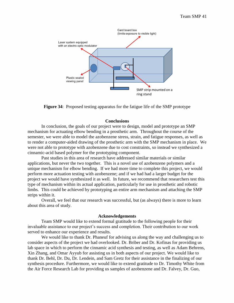
Team SMP 41
Figure 34: Proposed testing apparatus for the fatigue life of the SMP prototype
Conclusions
In conclusion, the goals of our project were to design, model and prototype an SMP
mechanism for actuating elbow bending in a prosthetic arm. Throughout the course of the
semester, we were able to model the azobenzene stress, strain, and fatigue responses, as well as
to render a computer-aided drawing of the prosthetic arm with the SMP mechanism in place. We
were not able to prototype with azobenzene due to cost constraints, so instead we synthesized a
cinnamic-acid based polymer for the prototyping component.
Past studies in this area of research have addressed similar materials or similar
applications, but never the two together. This is a novel use of azobenzene polymers and a
unique mechanism for elbow bending. If we had more time to complete this project, we would
perform more actuation testing with azobenzene; and if we had had a larger budget for the
project we would have synthesized it as well. In future, we recommend that researchers test this
type of mechanism within its actual application, particularly for use in prosthetic and robotic
limbs. This could be achieved by prototyping an entire arm mechanism and attaching the SMP
strips within it.
Overall, we feel that our research was successful, but (as always) there is more to learn
about this area of study.
Acknowledgements
Team SMP would like to extend formal gratitude to the following people for their
invaluable assistance to our project’s success and completion. Their contribution to our work
served to enhance our experience and results.
We would like to thank Dr. Phaneuf for advising us along the way and challenging us to
consider aspects of the project we had overlooked. Dr. Briber and Dr. Kofinas for providing us
lab space in which to perform the cinnamic acid synthesis and testing, as well as Adam Behrens,
Xin Zhang, and Omar Ayyub for assisting us in both aspects of our project. We would like to
thank Dr. Behl, Dr. Du, Dr. Lendein, and Sam Gretz for their assistance in the finalizing of our
synthesis procedure. Furthermore, we would like to extend gratitude to Dr. Timothy White from
the Air Force Research Lab for providing us samples of azobenzene and Dr. Falvey, Dr. Guo,

Team SMP 42
and Romina Heymann for assisting and providing us with the light source. Finally, thank you to
Dr. Kipnis for lending us the glassware from the chemistry department.
The group would also like to thank Dr. Al-Sheikhly, Dr. Anderson. Dr. Lloyd. Dr.
Martinez-Miranda. Dr. Nie. Dr. Salamanca-Riba. Dr. Seog. Dr. Sita. Dr. Steffek, Dr. Wereley,
Dr. Wuttig for their contributions of information and direction over the course of our project that
was the foundation for our overall success.
It is because of the contributions of these individuals that we have learned and grown
through our Senior Capstone experience.
Team SMP 43
References
Autodesk: http://wikihelp.autodesk.com/Simulation_Mechanical/enu/2012/Help/0873-
Autodesk873/0885-Theoreti885/0887-Strain_B887#GUID-ECDCD9AB-BE65-43A3-
9ECB-D25C38606A3E
Behl, M. and Lendlein, A. (2007). Shape-memory polymers are an emerging class of active
polymers, 10(4), 20–28.
Cembran, A., Bernardi, F., Garavelli, M., Gagliardi, L., & Orlandi, G. (2004). On the
Mechanism of the cis-trans Isomerization in the Lowest Electronic States of Azobenzene:
S0, S1, and T1. Journal of the American Chemical Society,126(10), 3234-3243.
Chandler, .F., Clauser, C.E., McConville, J.T., aynolds, H.M., Young, J.W., “Investigation of
Inertial Properties of the Human Body”, U.S. Department of transportation, Contract No.
DOT-HS-017-2-315-1A.
Cheng, L., Torres, Y., Min Lee, K., McClung, A. J., Baur, J., White, T. J., & Oates, W. S.
(2012). Photomechanical bending mechanics of polydomain azobenzene liquid crystal
polymer network films. Journal of Applied Physics, 112(1), 013513.
doi:10.1063/1.4729771
Conjugated, T. M., & Langer, R. (2005). Light-induced shape-memory polymers ¨, 434(April),
695–697. doi:10.1038/nature03438.1.
Courtney, Thomas H.. "Fatigue of Engineering Materials ." Mechanical behavior of materials.
1990. Reprint. New York: McGraw-Hill, 2000. 579-580. Print.
Du, H., & Zhang, J. (2012). The synthesis of poly(vinyl cinnamates) with light-induced shape
fixity properties. Sensors and Actuators A: Physical, 179, 114–120.
doi:10.1016/j.sna.2012.02.001
Ekberg, A., “Design against fatigue”, Chalmers: Solid state mechnics, l(4), 1-4
Evans, D. A. (Director) (2006, October 25). Lecture Number 16: Cycloaddition Reactions-1.
Chemistry 206: Advanced Organic Chemistry. Lecture conducted from Harvard
University, Cambridge.
Fine, M. J., & Solovay, K. S. (1998). U.S. Patent No. 5,800,516. Washington, DC: U.S. Patent
and Trademark Office.
Flomenblit, J., Budigina, N., & Bromberg, Y. (1996). U.S. Patent No. 5,562,641. Washington,
DC: U.S. Patent and Trademark Office.
Harada, F., Sagae, K., & Nobuyoshi, M. (1991). U.S. Patent No. 5,037,427. Washington, DC:
U.S. Patent and Trademark Office.
Hess, R. L., & Bramfitt, J. E. (1996). U.S. Patent No. 5,545,210. Washington, DC: U.S. Patent
and Trademark Office.
Hibbeler, R. C. (2010). Chapter 9: Center of Gravity and Centroid . Engineering mechanics:
statics (12 ed., pp. 448-449). Upper Saddle River, N.J.: Pearson Education.
Iqbal, D., & Samiullah, M. (2013). Photo-Responsive Shape-Memory and Shape-Changing
Liquid-Crystal Polymer Networks. Materials, 6(1), 116–142. doi:10.3390/ma6010116
Jiang, H. Y., Kelch, S., & Lendlein, a. (2006). Polymers Move in Response to Light. Advanced
Materials, 18(11), 1471–1475. doi:10.1002/adma.200502266
Jong, I., & Springer, W. (2009). GC 2009-267 : Teaching von Mises Stress : From Principal
Axes To Non-Principal Axes.
Lee, K.M., Bunning, T.J., and White, T.J. (2012). “Autonomous, hands-free shape memory in
glassy liquid crystalline polymer networks.” Advanced Materials, 24(21), 2839-2843.
Team SMP 44
Lee, K.M., Koerner, H., Vaia, R.A., Bunning, T.J., and White, T.J. (2011). “Light-activated
shape memory of glassy, azobenzene liquid crystalline polymer networks.” Soft Matter,
7, 4318-4324.
Lendlein, A., Jiang, H., Jünger, O., & Langer, R. (2005). Light-induced shape-memory
polymers. Nature, 434(7035), 879-882.
Leng, J., Lan, X., Liu, Y., & Du, S. (2011). Shape-memory polymers and their composites:
Stimulus methods and applications. Progress in Materials Science, 56(7), 1077–1135.
doi:10.1016/j.pmatsci.2011.03.001
Long, K. N., Scott, T. F., Jerry Qi, H., Bowman, C. N., & Dunn, M. L. (2009). Photomechanics
of light-activated polymers. Journal of the Mechanics and Physics of Solids, 57(7), 1103–
1121. doi:10.1016/j.jmps.2009.03.003
Mather, P. T., Luo, X., & Rousseau, I. a. (2009). Shape Memory Polymer Research. Annual
Review of Materials Research, 39(1), 445–471. doi:10.1146/annurev-matsci-082908-
145419
Matweb: http://www.matweb.com/search/DataSheet.aspx?MatGUID=929d1edc9224449f8009
dd5c9f47a994&ckck=1
Matweb:http://www.matweb.com/search/DataSheet.aspx?MatGUID=6532b02c347d446b824139
0cc04a3e66&ckck=1
Merino. E., Ribagorda. M., (2012)., Control over molecular motion using the cis-trans
photoisomerization of the azo group, J. Org. Chem., 8, 1071-1090, doi:
10.3762/bjoc.8.119
Otsuka, K., & Wayman, C. M. (Eds.). (1999). Shape memory materials. Cambridge University
Press.
Programme, P. R. (n.d.). Manufacturing guidelines Physical Rehabilitation Programme.
Shao, J., Lei, Y., Wen, Z., Dou, Y., & Wang, Z. (2008). Nonadiabatic simulation study of
photoisomerization of azobenzene: Detailed mechanism and load-resisting capacity. The
Journal of chemical physics, 129, 164111.
Sokolowski, W., Metcalfe, A., Hayashi, S., Yahia, L’Hocine, Y., aymond, J. (2007). Medical
applications of shape memory polymers. Biomedical Materials, 2, S23- S27.
Takashima, K., Rossiter, J., & Mukai, T. (2010). McKibben artificial muscle using shape-
memory polymer. Sensors and Actuators A: Physical, 164(1-2), 116–124.
doi:10.1016/j.sna.2010.09.010
Tiago. M.L., Ismail-Beigi. S., and Louie S.G., Photoisomerization of azobenzene from first-
principles constrained density-functional calculations, J. Chem. Phys.,
122,094311(2005); doi: 10.1063/1.1861873
Toshchevikov, V., Saphiannikova, M., & Heinrich, G. (2009). Theory of light-induced
deformations in azobenzene polymers: structure-property relationship. (J. G. Grote, F.
Kajzar, & R. Zamboni, Eds.), 7487, 74870B–74870B–12. doi:10.1117/12.830967
Trepanier, C., Leung, T. K., Tabrizian, M., Yahia, L. H., Bienvenu, J. G., Tanguay, J. F., ... &
Bilodeau, L. (1999). Preliminary investigation of the effects of surface treatments on
biological response to shape memory NiTi stents. Journal of biomedical materials
research, 48(2), 165-171.
White, T. J., Tabiryan, N. V., Serak, S. V., Hrozhyk, U. a., Tondiglia, V. P., Koerner, H., Vaia,
R. a., et al. (2008). A high frequency photodriven polymer oscillator. Soft Matter, 4(9),
1796. doi:10.1039/b805434g