lifting options for stratospheric aerosol geoengineering ... 10.1098/rsta.2011.0639 phil. trans. r....
TRANSCRIPT

doi: 10.1098/rsta.2011.0639, 4263-4300370 2012 Phil. Trans. R. Soc. A
Peter Davidson, Chris Burgoyne, Hugh Hunt and Matt Causier systemsgeoengineering: advantages of tethered balloon Lifting options for stratospheric aerosol
References
related-urlshttp://rsta.royalsocietypublishing.org/content/370/1974/4263.full.html#
Article cited in: l.html#ref-list-1http://rsta.royalsocietypublishing.org/content/370/1974/4263.ful
This article cites 24 articles, 3 of which can be accessed free
Subject collections
(6 articles)structural engineering � (21 articles)environmental engineering �
(43 articles)atmospheric science � collectionsArticles on similar topics can be found in the following
Email alerting service herein the box at the top right-hand corner of the article or click Receive free email alerts when new articles cite this article - sign up
http://rsta.royalsocietypublishing.org/subscriptions go to: Phil. Trans. R. Soc. ATo subscribe to
on August 6, 2012rsta.royalsocietypublishing.orgDownloaded from

Phil. Trans. R. Soc. A (2012) 370, 4263–4300doi:10.1098/rsta.2011.0639
Lifting options for stratospheric aerosolgeoengineering: advantages of tethered
balloon systemsBY PETER DAVIDSON1, CHRIS BURGOYNE2,*, HUGH HUNT2
AND MATT CAUSIER2
1Davidson Technology Limited, 8a Village Walk, Onchan, Isle of Man2Department of Engineering, University of Cambridge, Trumpington Street,
Cambridge CB2 1PZ, UK
The Royal Society report ‘Geoengineering the Climate’ identified solar radiationmanagement using albedo-enhancing aerosols injected into the stratosphere as the mostaffordable and effective option for geoengineering, but did not consider in any detail theoptions for delivery. This paper provides outline engineering analyses of the options,both for batch-delivery processes, following up on previous work for artillery shells,missiles, aircraft and free-flying balloons, as well as a more lengthy analysis of continuous-delivery systems that require a pipe connected to the ground and supported at aheight of 20 km, either by a tower or by a tethered balloon. Towers are shown notto be practical, but a tethered balloon delivery system, with high-pressure pumping,appears to have much lower operating and capital costs than all other delivery options.Instead of transporting sulphuric acid mist precursors, such a system could also beused to transport slurries of high refractive index particles such as coated titaniumdioxide. The use of such particles would allow useful experiments on opacity, coagulationand atmospheric chemistry at modest rates so as not to perturb regional or globalclimatic conditions, thus reducing scale-up risks. Criteria for particle choice are discussed,including the need to minimize or prevent ozone destruction. The paper estimates thetime scales and relatively modest costs required if a tethered balloon system were tobe introduced in a measured way with testing and development work proceeding overthree decades, rather than in an emergency. The manufacture of a tether capable ofsustaining the high tensions and internal pressures needed, as well as strong winds, isa significant challenge, as is the development of the necessary pumping and dispersiontechnologies. The greatest challenge may be the manufacture and launch of very largeballoons, but means have been identified to significantly reduce the size of such balloonsor aerostats.
Keywords: geoengineering; climate change; tethered balloons; stratospheric particle injection
*Author for correspondence ([email protected]).
One contribution of 12 to a Discussion Meeting Issue ‘Geoengineering: taking control of our planet’sclimate?’.
This journal is © 2012 The Royal Society4263
on August 6, 2012rsta.royalsocietypublishing.orgDownloaded from

4264 P. Davidson et al.
1. Introduction
Lord Rees commented in the foreword to the Royal Society report ongeoengineering, ‘many proposals for geoengineering have already been made—but the subject is bedevilled by much doubt and confusion. Some schemes aremanifestly far-fetched; others are more credible, and are being investigated byreputable scientists; some are being promoted over-optimistically’ [1].
At an Engineering and Physical Sciences Research Council/NaturalEnvironment Research Council workshop in March 2010, proposals were invitedfor preliminary research into geoengineering by various methods includingsolar radiation management (SRM) by particle injection into the stratosphere.At the workshop, the idea of a high-altitude tethered balloon delivery system,with ultra-high pressure pumping to elevate fluids or particle slurries, appeared tooffer significant advantages over other delivery options. A proposal to investigatethe desired particle properties, the method of their delivery and modellingtheir impact on the climate was funded. The dispersion at altitude of particlesmanufactured at ground level, with tailored size distributions and coatings mayprovide benefits, such as reduced or negligible ozone impact, not readily availableto other delivery options. This paper reviews the merits of this idea alongsidethose of other delivery options.
Previously, Blackstock et al. [2] considered the scientific and engineeringrequirements of various technologies but did not consider costs. Others haveprovided cost estimates for certain technologies such as aircraft and navalartillery but did not consider as many delivery options [3–5]. Considerationhas also been given by some of the authors to the use of tetheredaerostats, manufactured particles, drag reduction strategies and dispersiontechnologies [6].
The lead time required for implementation of any injection system is aparticularly important criterion if the real value of SRM options is to provide aninsurance policy against global warming and its effects: rising greenhouse gasconcentrations may trigger significant transients such as runaway methaneemission from melting arctic permafrost, major acceleration of ice sheet melting,or methane clathrate release from the ocean floor. Should any of these ‘tippingpoints’ be encountered then immediate measures will be required to reduce globaltemperature quickly in order to avoid unprecedented social, environmental andeconomic costs. For this reason, it is important to assess the time needed fora candidate geoengineering strategy to have any significant impact on globaltemperature. Modifying greenhouse gas concentrations is likely to take far toolong: time constants for natural processes to reduce greenhouse gases in theatmosphere are hundreds of years, and the time constant for man-made emissionsto fall to insignificant levels is likely to be similar. Carbon dioxide removaltechniques might possibly have an impact in 50 years [7], but SRM technologieswould appear to be the only options capable of achieving global temperaturestabilization, or reduction, on a time scale of a few years commensurate with theuncertainties of predicting significant transients. Two general arguments againstall SRM techniques are that they do not directly retard ocean acidification, andtheir regional impact is difficult to assess with current climate models, but theymight at least buy time and allow the world to avoid some of the more extremetemperature or precipitation scenarios.
Phil. Trans. R. Soc. A (2012)
on August 6, 2012rsta.royalsocietypublishing.orgDownloaded from

Stratospheric aerosol geoengineering 4265
2. Particle choice and properties
The choice of particle is receiving close attention; hitherto, it had been assumedthat aerosols would be sulphuric acid mists similar to those produced byvolcanoes. Such natural mists are efficient scatterers of visible light from theSun and very inefficient scatterers of infrared radiation from the Earth, eventhough they are slightly smaller than optimum [4]. However, it may be possibleto consider using other particles with better properties. The Royal Society reporton geoengineering comments [1]
Various other types of stratospheric aerosol particles have also been suggested (Telleret al. 1997; Blackstock et al. 2009; Keith 2009; Katz 2009) [2,8–10]. Engineered aerosolsmight enable scattering that did not produce so much diffuse illumination, potentiallycircumventing a significant side-effect of sulphate aerosols. Alternative materials might alsoavoid the coagulation and vaporisation problems that will be significant for sulphate aerosols.Finally, it is possible that advanced engineered particles could be designed that had longerlifetimes, or that were lofted out of the lower stratosphere, so reducing the impact of theaerosol on ozone chemistry, or enabling radiative forcing to be concentrated in speciallocations such as the polar regions.
If other particles are to be designed and manufactured for use in a suspendedpipe system, they will need particular properties to be attractive alternatives tothe use of a sulphuric acid aerosol. As well as having a high refractive index andsuitable particle size to maximize solar radiation scattering, they should, for agiven amount of scattering,
— minimize stratospheric ozone destruction by having a lower heterogeneousreaction rate than sulphuric acid aerosols for the following reactions:(i) 2O3 → 3O2
(ii) N2O5 + H2O → 2HNO3
(iii) HCl + ClONO2 → Cl2(g) + HNO3
— minimize regional changes in precipitation by reducing stratosphereheating through having a lower absorption of solar radiation than forsulphuric acid aerosols.
The particle surface coating technology needs also to:
— Provide dispersion of the particles in the chosen carrier fluid both inthe pipe at very high pressures (at up to 6000 bar), and at the point ofdischarge under low pressure (less than 0.1 bar, −50◦C). Electrical fieldgradients are likely to be significant at the start of the plume and may beused to reduce coagulation. The carrier fluid composition must ensure anunreactive, buoyant plume at 20 km altitude even with significant particleloading. Nitrogen might be a suitable candidate carrier gas, with addedhydrogen to ensure necessary buoyancy.
— Be stable for at least two years in the cold but high UV conditions of theupper atmosphere.
— Be designed to minimize nucleation effects in the troposphere after theparticles have left the stratosphere.
Phil. Trans. R. Soc. A (2012)
on August 6, 2012rsta.royalsocietypublishing.orgDownloaded from

4266 P. Davidson et al.
Manufacture of the particles should be low cost, with a low environmental impact,and the particles must have negligible toxicity. Ideally, there should be a sufficientsupply of the relevant raw materials to ensure availability for at least a century.
Various high refractive index particle systems could be considered but titaniumdioxide (TiO2) is a promising candidate. No other particle comes anywhere closeto its properties: it has a high refractive index, its safety has been well researchedand it is produced in industrial quantities. Coated TiO2 particles of a sizeapproximately 0.15–0.25 mm in diameter would be suitable. They are only slightlysmaller than those already produced for most paints and for providing opacityin many other applications, e.g. in paper, plastic films, inks, some foodstuffs.A much smaller particle size (approx. 0.05 mm) is already made to scatter UV insunscreens. Titanium dioxide has the highest refractive index of any pigmentarysubstance currently manufactured on a relevant scale which is stable in air andnon-toxic. It also has a low visible light absorption, and there is a vast experiencein manufacturing nanometre thickness coatings on titanium dioxide to controlsurface properties [11,12].
The use of different coatings allows the possibility of minimizing atmosphericchemistry effects. Current TiO2 particle sizes are optimized for light scatteringin close-packed systems, but the existing manufacturing units could easily bemodified to produce the slightly smaller sizes for light scattering in a dispersedenvironment [11]. The inorganic/organic coating systems have the potential tobe modified to give stable hydrophobic surfaces with a variety of chemistries thatmay reduce ozone destruction to a lower level than that of sulphuric acid mists.Other potential high refractive index particle systems should also be considered.
By conveying the particles up the pipe in a supercritical fluid, and makinguse of existing compact and lightweight micronizing technologies employing theconveying fluid for motive power, there is the potential to create a well-dispersedaerosol system at 20 km altitude.
Early experiments could be carried out from free-flying balloons or fast jets,possibly followed in due course with a high-pressure pipe supported from arelatively small (approx. 100 m diameter) balloon. The latter system would beable to create progressively larger plumes at altitude to enable the atmosphericchemistry, dispersion scattering and electrical effects to be studied. Much of thetechnology to examine such plumes is available from existing atmospheric sciencestudies using satellites, free-flying balloons, aircraft and ground-based equipment.
Notwithstanding all of the above, the use of H2S as a precursor systemfor sulphuric acid aerosols has the great advantage of generating almost fivetimes the mass of the material lofted, through the supply of oxygen fromthe stratosphere, i.e. H2S + 2O2 → H2SO4. A particulate system also needs aconveying gaseous material to be lofted. Scattering calculations and processflow analyses indicate that the conveying material mass flow and the extramass provided by the ‘free oxygen’ are likely to negate mass reduction throughhigher scattering per unit volume. However, creating an appropriate sulphuricacid mist at altitude in a representative environment poses significant problems.Without that capability, the slowness of the reaction of SO2 to H2SO4 means thatlocal, small-scale experiments would be impossible: atmospheric circulation woulddisperse precursor material (SO2 or H2S) around the planet before sulphuric acidmists would form, and also before suitable measurements could be carried out ontheir effects [4].
Phil. Trans. R. Soc. A (2012)
on August 6, 2012rsta.royalsocietypublishing.orgDownloaded from
Stratospheric aerosol geoengineering 4267
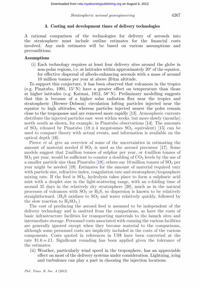
3. Costing and development times of delivery technologies
A rational comparison of the technologies for delivery of aerosols intothe stratosphere must include outline estimates for the financial costsinvolved. Any such estimates will be based on various assumptions andpreconditions.
Assumptions(i) Each technology requires at least four delivery sites around the globe in
non-polar regions, i.e. at latitudes within approximately 20◦ of the equator,for effective dispersal of albedo-enhancing aerosols with a mass of around10 million tonnes per year at above 20 km altitude.
To support this conjecture, it has been observed that volcanoes in the tropics(e.g. Pinatubo, 1991, 15◦ N) have a greater effect on temperature than thoseat higher latitudes (e.g. Katmai, 1912, 58◦ N). Preliminary modelling suggeststhat this is because of a higher solar radiation flux near the tropics andstratospheric (Brewer–Dobson) circulation lofting particles injected near theequator to high altitudes, whereas particles injected nearer the poles remainclose to the tropopause and are removed more rapidly [13]. Atmospheric currentsdistribute the injected particles east–west within weeks, but more slowly (months)north–south as shown, for example, in Pinatubo observations [14]. The amountsof SO2 released by Pinatubo (18 ± 4 megatonnes SO2 equivalent) [15] can beused to compare theory with actual events, and information is available on theoptical depth [16].
Pierce et al. give an overview of some of the uncertainties in estimating theamount of material needed if SO2 is used as the aerosol precursor [17]. Somemodels suggest that 2 million tonnes of sulphur per year, or 4 million tonnes ofSO2 per year, would be sufficient to counter a doubling of CO2 levels by the use ofa smaller particle size than Pinatubo [18]; others say 10 million tonnes of SO2 peryear might be needed [19]. Estimates for the amount of material required varywith particle size, refractive index, coagulation rate and stratosphere/tropospheremixing rate. If the feed is SO2, hydrolysis takes place to form a sulphuric acidmist with a droplet size in the light-scattering range, with an e-folding time ofaround 35 days in the relatively dry stratosphere [20], much as in the naturalprocesses of volcanoes with SO2 or H2S, so dispersion is known to be relativelystraightforward. (H2S oxidizes to SO2 and water relatively quickly, followed bythe slow reaction to H2SO4.)
The cost of producing the aerosol feed is assumed to be independent of thedelivery technology and is omitted from the comparisons, as have the costs ofbasic infrastructure facilities for transporting materials to the launch sites andintermediate storage. Personnel costs associated with running the various facilitiesare generally ignored except when they become material to the comparisons,although some personnel costs are implicitly included in the costs of the variouscomponents. Costs quoted in references in US$ have been converted at therate $1.6 = £1. Significant rounding has been applied given the tolerance ofthe estimates.
(ii) Weather, particularly wind speed in the troposphere, has an appreciableeffect on most of the delivery systems under consideration. Lightning, icingand turbulence can play a part in choosing the injection locations.
Phil. Trans. R. Soc. A (2012)
on August 6, 2012rsta.royalsocietypublishing.orgDownloaded from

4268 P. Davidson et al.
20 40 60 80 1000
4
8
12
16
20
wind speed (m s–1)
heig
ht a
bove
sea
leve
l (km
)
Figure 1. Variation of wind speed with height (maximum of 6 hourly data at 33◦N).
The wind speed shown in figure 1 is taken from the maximum of the 6 hourly‘instantaneous’ data for the wind (ERA-Interim) at 33◦ N [21]. The effect of thejet stream at an elevation of about 11 km is clearly visible, as is the reductionto relatively steady conditions at 20 km. The figures used reflect extremes in thetropics if very dry (low storm intensity) regions are used for the injection points.Surface drag reduces the wind speed at the Earth’s surface. For some calculationsthe figures will need to be increased; very short gusts have structural effects, andthese figures do not include the effect of tropical storms that can cause verylarge wind speeds at low levels. The peak wind speed at 20 km is only about50 m s−1, while the maximum peak wind speed measured in a year (1953) overNorth America was 136 m s−1 [22]. While these data are relatively old, it remainsthe most consistent dataset available for peak wind speeds and provides a usefulsemi-continuous wind velocity function for optimizing engineering design.
The density variation (figure 2) is also important, falling to about a 14th of itssurface value at 20 km.
(iii) The systems considered below can be classified in various ways. Twocriteria are of particular importance: the length of time the delivery deviceremains in the stratosphere and the reusability of the components.
It is assumed that:— those systems where the delivery device follows a ballistic trajectory will
remain in the stratosphere for a very short time (of the order of seconds)and will therefore require an extremely rapid dispersal process, either bymeans of detonations or by using a system where the liquid or solid willnaturally disperse without mechanical assistance and
— those systems with a dwell time in the stratosphere measured in minutesor hours, such as aircraft or cruise missile technology, could use some formof mechanical dispersion.
Phil. Trans. R. Soc. A (2012)
on August 6, 2012rsta.royalsocietypublishing.orgDownloaded from

Stratospheric aerosol geoengineering 4269
0.5 1.0 1.50
4
8
12
16
20
heig
ht a
bove
sea
leve
l (km
)
air density (kg m–3)
Figure 2. Variation of air density with height.
These short residence time systems are effectively batch processes. It is alsoassumed that:
— those systems with a time in the stratosphere of many days or months,such as tethered balloons or airships, could use quite sophisticateddispersal technology and can be expected to give a much morecontrolled dispersion. There will be a weight penalty since the machinerywould have to be carried to an altitude of 20 km, and powered continuouslyat this height.
These long residence time systems are effectively continuous delivery processes.
(iv) The options for reusability raise different issues.
— For ‘one-shot’ systems, the multiple delivery elements have to becheap. The environmental cost of the redundant components mustbe considered, both in terms of safety (heavy pieces falling back toEarth or the possibility of noxious materials being strewn around) andappearance (litter).
— Systems with limited reusability allow components to be recovered andeither used again immediately or refurbished. In this way, many ofthe drawbacks of one-shot systems are removed. However, the costsof recovery must be taken into account, or at least an allowancemade for the difficulty of making the system components return tobase autonomously. The cost of regularly providing replacements fordamaged components must also be considered.
— Systems with complete reusability. Systems that provide for continuoususe, or reuse over a long period, may justify high initial costs andcomplexity.
Phil. Trans. R. Soc. A (2012)
on August 6, 2012rsta.royalsocietypublishing.orgDownloaded from

4270 P. Davidson et al.
(v) The development times discussed assume a ‘Manhattan project approach’where ‘political will’ ensures almost unlimited access to relevant resources:people, finance, facilities. Such a position might develop when obvioussocietal stress was arising from global warming, but would have greaterattendant risks.
(a) Free-flying balloons
The concept of using cheap latex balloons, similar to weather balloons, tolift a payload of particles has been considered by a number of authors [1,2,4].The analysis given here closely follows that in COSEPUP [5] but uses differentvalues for some parameters. A 20 m diameter balloon has been assumed to be themaximum practicable.
By application of Archimedes’ principle, a payload of around 250 kg can belofted to 20 km (where the density of air is around 0.08 kg m−3) by a singlehydrogen-filled balloon of 20 m in diameter. A latex or nylon balloon, typical ofthose routinely used for scientific purposes, would weigh around 25 kg, and 20 kgis allowed for a canister and valve needed to release the payload. It follows that40 million balloon flights per year are required to loft 10 million tonnes of aerosol.
The price of latex in July 2010 was £1.4 kg−1 [http://www3.lgm.gov.my/mre,date accessed: 1 July 2010] and in July 2008 the hydrogen price stood at around£1.6 kg−1 [http://www.hydrogencarsnow.com/blog2/index.php/hydrogen-fuel-production/global-hydrogen-inc-lowers-price-of-hydrogen-to-247-per-gallon, dateaccessed: 31 October 2010]. The cost for a canister and valve in bulk productionis estimated at £30.
The use of a premixed hydrogen/H2S or SO2 system as the lifting gas has beenproposed [4]; this is entirely feasible but would increase the volume and thereforethe number of balloons by a factor of 5 with a consequential increase in cost.
(i) Single-use balloons
If individual balloons are not reused, one balloon is required per flight. Thetotal cost of hydrogen is £1.4 billion, that of balloon fabric is £4 billion (withfabrication costs on this scale being minimal when compared with material costs),and that of canisters is £1.2 billion per year.
These numbers imply a total cost of approximately £7 billion per year, andwould be expected to increase in line with energy prices.
Global annual production of latex and hydrogen is 21 million tonnes[http://www.lgm.gov.my/nrstat/T1.htm, date accessed: 31 October 2010] and 70million tonnes [http://www.azom.com/news.asp?NewsID=20711, date accessed:31 October 2010] respectively, so these requirements represent 11 and 1.4 per centof current global production. The largest delays in producing a single-use balloonsystem are likely to be the difficulties of scaling up production and the provisionof ground facilities, so a system should be deployable within 5 years in extremis.
Latex is naturally biodegradable but the mechanism is not well understood [23].It would need to be made more rapidly biodegradable, without affecting itsstrength, otherwise the environmental impact of balloons littering the Earth’ssurface would be severe, particularly to marine life. The social impact wouldbe moderate, mostly affected by the extensive effect on air traffic given theunpredictability of the flight path and the frequency of balloon launches. Thespent hydrogen would combine with oxygen in the atmosphere to release about
Phil. Trans. R. Soc. A (2012)
on August 6, 2012rsta.royalsocietypublishing.orgDownloaded from

Stratospheric aerosol geoengineering 4271
10 million tonnes of water into the stratosphere each year; i.e. far less thanthe 500 million tonnes threshold at which significant effects on stratosphericcirculation might be expected [24].
(ii) Reusable balloons
Compared with the single-use balloon case, the number of balloons requiredfalls if they can be retrieved and reused. However, the cost and environmentalimpact of retrieving the spent balloons is likely to be significant, and could begreater than for single-use balloons since greater care would be needed in retrievalto ensure reuseability. Horizontal wind components of approximately 30–40 m s−1,averaged over a 20 km column, are typical. If a balloon flight lasts between 1 and3 h, with a rate of ascent around 4–12 m s−1, then the balloon will travel around150–450 km, which if all directions are equally probable, equates to a retrievalarea of up to 600 000 km2 around each launch station. In practice, the area overwhich the balloons would fall would be somewhat less, at least over short timescales, since the wind direction is not random.
Environmental damage and wear-and-tear are likely to restrict the lifetime ofeach balloon. A modern hot air balloon has a lifetime of approximately 700 flighthours. Time on the ground or in the sea would add to wear-and-tear. Keeping timeon the ground down to an average of 24 h, with 25 000 launches per day per site tomeet the four-site, 40 million balloon launches per year criterion, requires around4000 retrieval teams per site if each can pick up six balloons per day and coverapproximately 10–75 km2 in unpopulated terrain such as the Australian outback.If a larger number of sites were used, the number of teams would probably increasesince the balloons would typically be spread over a wider area.
A retrieval truck or boat with two operators might cost around £750 perday including fuel and depreciation. This would amount to an expenditure of16 000 teams × 365 × 750 ≈ £4.4 billion per annum (p.a.) plus launch costs forthe worst case and perhaps one quarter of this if high speed ascents and descentsare used. Assuming a round trip time from launch to launch of 3 days, at least300 000 balloons would be needed. If the balloons last an average of 20 flights,then 1.3 million new balloons are needed each year, and if each reusable ballooncosts twice as much as a throw-away one, the cost would be about £400 millionp.a. It is assumed that the hydrogen cannot be reused.
The total cost is thus approximately £1–4.4 billion p.a. for recovery + £4 billionp.a. hydrogen + £0.4 billion p.a. balloons, giving a total between £6 billion and£9 billion p.a., which is at least as high as the cost of throw-away balloons, largelybecause of the costs associated with recovery.
The technology is mostly available today, but there would probably need to bea large investment in establishing the necessary supply routes to the launch sites,which would probably mean a delay of 5–10 years before such a system couldbe deployed effectively. Although the pollution associated with discarded balloonfabric of one-shot balloons would not be incurred, the effects of the release oflarge amounts of hydrogen at high altitude would remain. There would be thesame issues associated with interference with air traffic, so social impacts wouldbe similar to single use balloons.
The idea of using superheated sulphur dioxide itself as both the buoyant gasand the payload of the balloon was rejected on the grounds that it would require
Phil. Trans. R. Soc. A (2012)
on August 6, 2012rsta.royalsocietypublishing.orgDownloaded from

4272 P. Davidson et al.
temperatures of around 600◦C, well above the melting point of any low costballoon fabric.
When considering the dispersal of aerosols other than those derived from aprecursor gas, both balloon options become more expensive on account of thedispersion equipment that has to be carried to high altitude.
(b) Towers
It is difficult to conceive of any tower option being achievable in theforeseeable future, but they have been proposed and should be considered. Bothenvironmental and social costs can perhaps be considered to be moderate ratherthan high but would be overwhelmed by the effects of the massive financialinvestment needed for towers.
(i) Conventional towers
Tall towers have been mentioned as potential options for elevating anddispersing material to stratospheric altitudes [4,25]; they would have theadvantage that they could operate continuously while providing human accessto the dispersal equipment, but the simple analyses described below show thatsuch a tower built with any materials currently available is not practicable andwould certainly be expensive (£250 billion in materials alone for each tower).Some savings could be obtained if a 15 km tower (rather than a 20 km tower)were built on a high plateau, for example, in the Andes or Himalayas.
A tall tower, to carry only its self-weight and wind loading, must satisfy twobasic criteria. It must be strong enough that the structural materials do not reachtheir limiting stresses and it must be stiff enough that it will not buckle. In thefirst instance, these criteria can be considered separately and, for illustration,the designs have been carried out in steel and in carbon fibre reinforced polymer(CFRP) with the material properties listed in table 1.
Strength design
A straight tower, of uniform cross section, will fail in compression when theheight is equal to s/rmg, where s is the strength of the material in compression,rm the density and g the acceleration owing to gravity. This is a limiting factorfor steel, giving a maximum height (without any safety factor) of approximately6.5 km. However, as will be seen below, this height can be exceeded if thetower tapers.
The predominant wind forces will be horizontal, so the tower will act primarilyin flexure as a vertical cantilever. Two tower cross sections are considered: oneformed from a single hollow tube as shown in figure 3a, rather like a continuallytapering cooling tower; the other from four legs with bracing, figure 3b, likethe Eiffel Tower or a UK electricity pylon. Most tower configurations can beapproximated to one or other of these cross sections.
The single tube will be thin walled and it is assumed that the wall thickness tis R/50. Thin-walled tubes in compression are at risk from local buckling wherethe thin wall crumples. For this failure mechanism to be avoided stiffeners inthe form of internal bracing will probably be required but it is assumed that thestiffeners are light enough to be neglected in the calculation of tower mass. For
Phil. Trans. R. Soc. A (2012)
on August 6, 2012rsta.royalsocietypublishing.orgDownloaded from

Stratospheric aerosol geoengineering 4273
(a) (b)
R/50
D/25
D
R
bracing
Figure 3. Alternative tower cross sections. R and D vary with height.
Table 1. Comparisons of 20 km tower designs.
steel CFRP
material propertiesdensity (kg m−3) 7800 1500allowable stress (MPa) 500 1500Young’s modulus (GPa) 200 120cost (£ t−1) 800 4000
cylindrical tower to resist wind onlydiameter at base (m) 134 52total weight of material (t) 18.3 × 10⁶ 657 × 103
gcr (m s−2) 0.166 0.104
4-legged braced tower to resist wind onlyleg spacing at base (m) 256 53total weight of material (t) 15.4 × 10⁶ 217 × 103
gcr (m s−2) 0.017 0.0131
uniform cylindrical tower to resist bucklingdiameter (m) — 1000total weight of material (t) — 942 × 106
uniform 4-legged braced tower to resist bucklingleg spacing (m) — 1000total weight of material (t) — 302 × 106
shaped cylindrical tower to resist wind and bucklingdiameter (m) 1030 508total weight of material (t) 1.09 × 10⁹ 62 × 106
material cost (£billion) 872 2484-legged braced tower to resist buckling
leg spacing (m) 6130 1460total weight of material (t) 8.88 × 10⁹ 163 × 106
material cost (£billion) 7040 652
the truss, a significant amount of bracing would be required, as in an electricitypylon. It will be assumed that this bracing weighs as much as the four main legsand attracts the same amount of wind load. The diameter of each leg d is relatedto the overall tower width D by taking D/d fairly arbitrarily as 25.
Phil. Trans. R. Soc. A (2012)
on August 6, 2012rsta.royalsocietypublishing.orgDownloaded from

4274 P. Davidson et al.
20 40 60 800
4
8
12
16
20
radius of tube, R (m)
heig
ht a
bove
sea
leve
l (km
)
Figure 4. Variation of principal diameter of single tube to resist wind loads only (solid line, steel;dashed line, CFRP).
The steady wind load on the tower is given by F = (1/2)raCDv2A, where Fis the force, ra the air density, CD the drag coefficient, A the area facing thewind and v the wind speed. The wind speeds in figure 1 certainly underestimatethe maximum 3 s gust normally used for structural design but are used here inthe absence of better data. The drag coefficient depends on Reynolds number(Re), but for the structures and wind speeds being considered Re is greater than8 × 104 so CD can conservatively be taken as 0.5 (e.g. [26]).
To determine the section dimensions the loads are integrated from the top ofthe tower downwards, giving a vertical moment (from the wind) and an axialforce (from the self-weight). The top of the cylindrical tower is assumed to havea radius R of 0.5 m and the truss a width D of 1 m. By computing the sum ofthe axial stress and the bending stress and comparing this total with the limitingmaterial stress sy , the required diameter at each level can be found. No allowancehas been made for the deflection of the tower above the point in question, whichwould increase the forces and hence increase the size of the tower cross section.For the hollow tube design, the variation of R with height is shown in figure 4.For steel, the radius at the base is about 68 m with a total weight of steel of about19 million tonnes. Using a lighter material such as CFRP the width increases lessrapidly, thus reducing the wind load, so R at the base is only 26 m with a totalweight of 0.66 million tonnes.
Similar effects are observed for the trussed form, with the variations shownin figure 5. The width of the steel truss increases quite rapidly towards thebase, indicating that the self-weight of the tower is starting to be a much moresignificant part of the load, although it is still possible to build a tower 20 kmtall. The trussed steel tower would have a total weight of 16 million tonnes, halfof which is assumed to be in some kind of bracing. There is much less weight inthe CFRP tower (218 000 tonnes).
Phil. Trans. R. Soc. A (2012)
on August 6, 2012rsta.royalsocietypublishing.orgDownloaded from

Stratospheric aerosol geoengineering 4275
100 200 3000
4
8
12
16
20
width of truss, D (m)
heig
ht a
bove
sea
leve
l (km
)
Figure 5. Variation in width of trussed form with height (solid line, steel; dashed line, CFRP).
Stability design
These dimensions, although large, give structures that are very slender. Evenfor the steel tube, the ratio of the height to the width at the base is about150, which is comparable to a very slender flag pole; such structures are verysusceptible to buckling under their own self-weight. In the first instance, bucklingwill be computed on the assumption that the towers are of uniform cross sectionfor their entire height. Later, tapered towers will be considered.
The well-known formula for Euler buckling load of a uniform pin-ended strutunder externally applied axial load is Pcr = p2EI/L2, where E is the Young’smodulus of the strut material, I its second moment of area and L its length.For a cantilever column, this buckling load must be divided by 4 to reflect thedifferent boundary conditions. When the buckling load comes from the tower’sown self-weight, the classical analysis of a uniform cantilever column gives a valuefor the critical load as
(qL)crit = 7.837EIL2
, (3.1)
where q is the weight per unit length [27]. The 7.837 factor can be compared withp2/4 = 2.467 for the end-loaded column; clearly, more load can be carried if it isdistributed evenly along the length rather than being carried at the end. But theself-weight is related to the material density and its cross-sectional area so theformula above can be rearranged to give
Lcrit = 7.837(
Ermg
) ( rL
)2, (3.2)
where r is the radius of gyration of the tower cross section. This formulaconveniently separates the buckling load into a material factor and a shapefactor. For a thin circular tube, the radius of gyration r is R/
√2 (and notably
Phil. Trans. R. Soc. A (2012)
on August 6, 2012rsta.royalsocietypublishing.orgDownloaded from

4276 P. Davidson et al.
is independent of the tube thickness). Even for a solid cylinder r only decreasesto R/2, so the values determined below apply to a wide range of cross-sectionoptions. For the truss r = D/(2
√2), allowing for the fact that half of the material
is in the bracing that contributes to the weight but not to the overall stiffness ofthe tower.
For steel, the required dimensions for the uniform tube at 6.5 km tall wouldgive r = 116 m whence R = 163 m for the tube or D = 327 m for the truss. For a20 km tower in CFRP, the radius of the uniform tube is 500 m. These dimensionsare clearly much larger than the values given by the strength analysis, but do nottake account of the reduction in section at the top: these values do not includeany safety factor.
For a tapered tube there is typically no closed-form solution. An approximateRayleigh analysis for the self-weight buckling load can be performed by assumingthe shape of the buckling mode and equating the strain energy of flexure to thework done by the load. The exact analysis would predict a lower buckling loadbecause the assumed shape will need more strain energy than the correct form.A commonly assumed buckling mode is to calculate the shape the tower wouldadopt if it were mounted horizontally and subjected to a gravity load [27]. By thisapproximation, the Rayleigh analysis for a uniform section (for which an exactsolution is available) overestimates the critical length by only 0.1 per cent, so itis reasonable to use the same approximation for a tapered tower.
A Rayleigh analysis indicates that the tapered steel tube tower, with R = 68 mat the base designed to resist the wind load in flexure, and with a mode predictedas above would buckle if the gravitational acceleration gcr were 0.166 m s−2. Sincethe buckling load will vary as R2, in order to make the tube buckle when gcr is9.81 m s−2, the tube dimensions would have to be increased by a factor of about7.6, giving a diameter at the base just over 1 km—which is a tube into which alarge football stadium would fit, complete with its carpark.
Similar analyses have been carried out for tubes and trusses in both steeland CFRP. The results are given in table 1. The ‘cheapest’ of these options(shown in bold in the table) is the shaped cylindrical tower in CFRP, at about£250 billion each. If four such towers are required, the cost would be of theorder of £1 trillion with 250 million tonnes of CFRP needed. No allowance hasbeen made for the difficulty of working at the altitudes needed. Figure 6 showsthese towers in comparison with some well-known landmarks to give some senseof scale.
The choice of materials for illustration was determined by material properties:since buckling is the governing condition, it is the specific modulus (E/r) thatmatters. Steel is stiff but heavy, so E/r is low, although it has the advantage ofbeing plentiful and relatively cheap. Carbon fibre has a similar modulus but islighter, so E/r is higher, but it is much more expensive. Most other structuralmaterials fall within this range; aluminium, for example, has both a modulus anda density that are about one-third those of steel, so the same amount of materialwould be needed, but at a much greater cost. The only way to make a significantimprovement would be to increase E , but this is limited (at least for organicmaterials) to the stiffness of the C–C bond, which is about 600 GPa, while at thesame time decreasing the density. Even if materials like graphene were availablein industrial quantities, they could only increase the specific modulus by at mosta factor of 2.
Phil. Trans. R. Soc. A (2012)
on August 6, 2012rsta.royalsocietypublishing.orgDownloaded from

Stratospheric aerosol geoengineering 4277
shapedCFRP tube
normal flight level
Everest
uniformsteel tube
Mont Blanc
Ben NevisBurj
KhalifaGreatPyramid
KVLYMast
CNTower
Figure 6. Comparison with notable tall structures (to scale).
Cost
There would be major supply issues for carbon fibre; current world productionis of the order of 50 000 tonnes p.a. [http://www.prnewswire.com/news-releases/reportlinker-adds-global-and-china-carbon-fiber-industry-report-2010-101893378.html, date accessed: 31 October 2010] with around $460 million for a 4800 tonnep.a. marginal increase including impregnation facilities [http://pubs.acs.org/cen/news/85/i08/8508notw2.html, date accessed: 31 October 2010]. At £60 000per tonne p.a., a few trillion pounds would be needed to increase carbon fibreproduction to the 10+ million tonnes p.a. needed to make the materials for thesetowers (approx. 100 million tonnes of carbon fibre) over a 10 year period. Even ifeconomies of scale meant that the cost of providing new plant reduced by 20 percent each time production was doubled, scaling up production gives a cost (£1–2trillion) that is comparable to the material cost quoted above, which neglectserection and fabrication costs. This approach would clearly need a very long time
Phil. Trans. R. Soc. A (2012)
on August 6, 2012rsta.royalsocietypublishing.orgDownloaded from

4278 P. Davidson et al.
to scale up production, followed by another very long time for the actual building;50–100 years does not seem unreasonable.
Significant savings could be achieved if the CFRP tower were founded ona 5 km plateau; the base diameter would reduce to 350 m, and both thematerial weight and its cost would reduce by 70 per cent to give a cost of £77billion per tower. Access to infrastructure would have to be provided, but the1000 km railway to Lhasa at 6000 m is reputed to have cost about $4 billion in2006 [http://news.bbc.co.uk/1/hi/4345494.stm, date accessed: 31 October 2010].Given the costs of a tower it would be worth constructing a road up Mt Everestand building a tower there!
The analysis presented above is simple, but reasonable. A more extensivevariational analysis to choose the optimal shape of the tower, to resist both globalbuckling and flexural stresses, could be carried out, which might reduce the totalweight of the tower. However, allowance would have to be made for reductionsin stability caused by wind-induced deflections (a full wind load on the CFRPtube gives a deflection at the top of about 0.35 km). The ability to resist localbuckling effects, distortions of the cross section and vibration of the tower whensubject to gusting winds, all of which have been ignored here, would add weightto the tower. The foundations would need careful consideration, as would thetower’s susceptibility to earthquake and even possibly local effects of applying avery high point load to the Earth’s crust.
(ii) Guyed masts
Many of the existing studies of very tall towers, for example, Bolonkin [28], whoproposes towers 100 km tall, and others [29], avoid the problem of buckling byassuming that the tower can be guyed. This is also the normal form of constructionfor tall unoccupied structures such as transmitter towers. However, the guys at thetop of a 20 km tower would need to be about 30 km long. Depending on the degreeof sag the designer chooses to allow, the tension in a cable hanging as a catenarybetween two supports, without any external load, can be many times its ownweight [30]. The analysis is highly nonlinear [31], so it is difficult to come up witha simple factor without defining a very specific set of conditions, but if the ratioof the cable tension to the cable weight were a factor of 10, which would not beunreasonable, a material capable of supporting 300 km of itself in simple tensionwould be required, even before taking into account a safety factor, difficulties ofanchorage, or creep. The only material commercially available at present wouldbe poly-p-phenylenebenzobisoxazole (PBO); graphene and nanotubes might bepossible if the strengths observed on minute quantities in laboratories could bereproduced in bulk but this has yet to be demonstrated. There are other issues:allowing more sag reduces the tension, but in turn reduces the effectiveness ofthe guys and allows the mast more freedom to move. The vertical componentof the guy forces adds to the weight of the mast, thus exacerbating the veryproblem they are designed to solve. Inclined stay cables in bridges are knownto be susceptible to wind-induced vibration [32] and are often themselves guyedwith counter-cables and provided with dampers.
The guys would impose very large lateral loads at the top of the tower; oncein place, the tower should be in equilibrium, but during erection it would not bein balance unless very complex rigging schemes were devised. It is no coincidence
Phil. Trans. R. Soc. A (2012)
on August 6, 2012rsta.royalsocietypublishing.orgDownloaded from

Stratospheric aerosol geoengineering 4279
that the world’s tallest radio mast collapsed while an individual guy was beingreplaced [http://en.wikipedia.org/wiki/Warsaw_Radio_Mast, date accessed: 31October 2010].
It is believed that the complexities of design, construction and maintenancewould make the erection of a guyed tower impossible.
(iii) Inflatable towers
The construction of towers from inflatable tubes made from lightweightmaterials has been proposed [33]. That idea was used as the basis for a towerdesigned to reach an altitude of 20 km from a mountain-top plateau at a heightof 5 km.
Unfortunately, no account is taken of sideways loads because of even moderatewinds, to say nothing of jet streams, and a cursory analysis shows such aproposition is impracticable with any currently known construction materials.In addition, there is an error in the original concept, which assumes that theprestress from the internal pressure counteracts the structure’s own weight,thereby preventing buckling, which is then ignored. But the prestress is partof a set of purely internal, self-equilibrating, forces, and although they mightprevent local buckling of the skin they cannot prevent global buckling. Inflatabletowers would be subject to exactly the same buckling conditions as have beendescribed above. There is a direct analogy (although in reverse) with a bicyclebrake cable; no matter how hard the cyclist applies the brake, the cable does notbuckle because the compression in the cable sheath is equilibrated by an equaland opposite tension in the brake cable.
(c) Aircraft
Systems based on aircraft have the advantage of using modified militaryvehicles; they can loiter in the stratosphere long enough to disperse the particleseffectively and would be reusable. They have the disadvantage that there wouldbe a significant energy cost in getting to the required height, and there would bea significant modification cost. The analysis below is adapted from that given byRobock et al. [4].
(i) Fast jets (F-15)
The F-15 has a maximum payload of around 10 tonnes [http://www.aerospaceweb.org/aircraft/fighter/f15, date accessed: 31 October 2010] so injecting 10million tonnes of aerosols into the atmosphere requires around a million flightsper year. If each plane is capable of performing three 2 h flights per day, orroughly 1000 flights per year, a fleet of 1000 planes should be able to deliverthe intended annual payload. The cost per plane is about £25 million. A fleetof 1000 modified planes would therefore incur a total capital cost of £25 billion.As the F-15 has a lifetime of only around 16 000 flight hours [http://www.fas.org/programs/ssp/man/uswpns/air/fighter/f15.html, date accessed: 31 October2010] the planes would need to be replaced every 8 years, the annualized averagereplacement cost would therefore be around £3 billion.
The operating costs are classified, but for tanker planes such as the KC-135 afigure of $4.6 million is quoted for 435 flight hours in 2003 dollars, which translatesto about £8000 per flight hour today [http://www.gao.gov/new.items/d03938t.
Phil. Trans. R. Soc. A (2012)
on August 6, 2012rsta.royalsocietypublishing.orgDownloaded from

4280 P. Davidson et al.
pdf, date accessed: 31 October 2010]. It is assumed that costs for fast jets are atleast as high. The annual operating costs for 1000 planes performing 2000 flighthours work out at £16 billion. The total cost for fast jets is thus £25 billion initialcapital + £3 billion replacement p.a. + £16 billion operating costs p.a.
(ii) Tanker jets (KC-10 and KC-135)
The analysis is similar to the section above but the maximum altitude thetanker jets can reach is below that needed to get above the tropopause except inpolar regions where injection is less effective. The payload of the KC-10 is around80 tonnes [http://www.af.mil/information/factsheets/factsheet.asp?fsID=109,date accessed: 31 October 2010], so with 1000 flights p.a. a total of 125 planeswould be required. In 1998, the KC-10 unit cost was $88 million, correspondingto a cost today of £70 million or £9 billion for a fleet of 125. At 40 000 flighthours [http://www.fas.org/programs/ssp/man/uswpns/air/fighter/f15.html,date accessed: 31 October 2010], the lifetimes are considerably longer than thoseof the F-15 and thus a fleet replacement would only be necessary every 20 years.On average, therefore, replacement capital costs for planes amount to £440 millionp.a. For 125 planes operating costs are 125 × 2000 flight hours × £8000 = £2billion. The total cost for tanker jets would be £9 billion capital + £0.44 billionreplacement p.a. + £2 billion operating costs p.a.
Older KC-135 tankers have a lower payload of around 40 tonnes [http://www.aerospaceweb.org/aircraft/transport-m/c135, date accessed: 31 October 2010],requiring a fleet of 250 planes. The unit cost is about £32 million leading toa capital cost of £8 billion; if replaced every 20 years the annualized cost wouldbe £400 million. With twice as many planes the operating costs would be doubledto about £4 billion p.a.
A hybrid system, in which the tanker carries both fuel and payload to 12 kmheight, and then transfers both to an F-15 using air-to-air refuelling techniquescould also be considered but has not been costed.
The costs, particularly for the small jets, are related to high-performancemilitary units; it could be expected that in the next 20–30 years the capital costsmight reduce somewhat. It would also be possible to consider designing a newplane tailored to the role of stratospheric particle injection [3]. However, theoperating costs would be likely to increase substantially in line with projectedincreases in energy costs. It should be possible to deploy a system such as thisrelatively quickly in an emergency, since a significant number of military jetsare available now and would need relatively little modification, but there wouldalmost certainly need to be new production if a permanent deployment wererequired. However, the political will required would be extreme reflecting thecosts and environmental impacts: these are roughly equivalent to about 5 per centof the current world wide passenger air traffic. It is presumed that the airbaseswould be located away from populated areas, to minimize noise pollution, andwould be kept away from normal flight routes to avoid air traffic problems, givinga high environmental but moderate social cost.
(d) Artillery
The largest naval artillery shell that could be fired in the twentieth centuryweighed 1510 kg using the 18 inch (0.457 m) barrel designed for HMS Furious in
Phil. Trans. R. Soc. A (2012)
on August 6, 2012rsta.royalsocietypublishing.orgDownloaded from

Stratospheric aerosol geoengineering 4281
the First World War [34]. The size of the gun was effectively limited by the size ofthe ship needed to support it; the barrel itself weighed 151 tonnes and had a verycomplex form of construction. Such guns had a muzzle velocity of 738 m s−1 anda horizontal range of about 37 km. Air drag (FD = (1/2)CDrv2A) is significant;equating the change in kinetic and potential energy with the frictional drag fora shell moving vertically gives
−dv
dh=
(gv
+ 12
CDAm
rv
). (3.3)
The drag coefficient for a streamlined projectile is reasonably constant in thesubsonic and trans-sonic regions at around CD = 0.5 and if it is assumed that airdensity decreases linearly with altitude from 1.2 to 0.1 kg m−3 at 20 km, then asimple numerical integration shows that if a 1510 kg shell were fired vertically itwould need to have a muzzle velocity of about 800 m s−1 (Mach 2.6) just to reach20 km. Smaller or heavier shells travel further.
It is assumed here that a similar gun, firing a 1500 kg shell, of which 800 kgis the aerosol payload, could be (re)developed relatively easily, and that it couldbe mounted on land, or on a specialized barge. The shells would need to berobust in order to withstand the accelerations when firing, and they would haveto be intelligent to disperse the payload at the right time: requirements that mightbe difficult to achieve simultaneously. To lift 10 million tonnes p.a. would require12.5 million shots a year. Inflation-adjusted estimates based on [5] for a slightlysmaller shell give a 2009 cost of £15 000 per shot, or about £200 billion for shellsper year. Gun barrels would need to be replaced at least every 3000 shots, becauseof wear and the effects of the very hot gases, at a cost of £1 million per barrel,and this rate of replacement assumes that relatively low accuracy is requiredfor stratospheric lofting. Total annual expenditure on barrels would therefore beabout £4.2 billion.
At a firing rate of 5 shots per hour, with continuous firing throughout theyear, some 290 barrels would be required at any one time, and each barrelwould need replacing every 25 days. There would be large setup costs but thesewould be small by comparison with the annual cost of shells (£200 billion) andbarrels (£4 billion).
These cost estimates may be considered too high because no account has beenmade that the shell price might be expected to reduce given the scale of the opera-tion but this will be offset by the environmental costs associated with recoveryand clean up of the spent shells. There would probably be public opposition tothe establishment of such a large arsenal of ‘weapons’, and this option has beenclassified with a moderate environmental and moderate social cost.
Although a system such as this would make use of 100-year-old technologies,there remain difficulties of making large gun barrels to withstand the very highpressures from the propellant, and it is probable that it would take many yearsand a large investment in heavy manufacturing facilities before an artillery systemcould be deployed.
(e) Missiles
Missiles differ from artillery in that they possess their own means of propulsionand guidance. There is no longer a need for the gun barrels that made up a largeproportion of the cost of the artillery option.
Phil. Trans. R. Soc. A (2012)
on August 6, 2012rsta.royalsocietypublishing.orgDownloaded from

4282 P. Davidson et al.
(i) Single-use missiles
‘Battlefield range ballistic missiles’ (BRBMs) such as the Pakistani Hatf-1have a range of 70 km, a weight of 1500 kg and a payload of 500 kg [http://www.fas.org/nuke/guide/pakistan/missile/hatf-1.htm, date accessed: 31 October2010]. If this could be modified without incurring too much expense to yield astratospheric rocket with a weight of approximately 2000 kg capable of lofting 1tonne of aerosols into the stratosphere, delivering 10 million tonnes of aerosols peryear would require 10 million flights per year. If particles are dispersed explosivelyand missiles are not retrieved, then this is also the annual number of rocketsrequired. As a possible point of reference for the price, a sophisticated long-range cruise missile such as the Tomahawk has a unit cost of around £300 000[http://www.fas.org/man/dod-101/sys/smart/bgm-109.htm, date accessed: 31October 2010], thus one might assume that the short range, technologically lesscomplex missiles required for stratospheric lofting might be procurable at a farreduced unit cost of £20 000. To inject the required amount of aerosol into thestratosphere would therefore cost 2 × 104 × 107 = £200 billion annually.
The technology is available today, but the systems are complex, so it is assumedthat it would take several years before production could be increased sufficientlyfor such a system to be deployed effectively. There would also be significantpollution from the exhaust gases, and expended missile casings. As with artillery,it is to be expected that there would be public objections to the significantexpansion in the production of war-like systems, resulting in a classification ofhigh environmental and moderate social impact.
(ii) Retrievable missiles
The cost of missiles can be significantly reduced if individual missiles arereused, in which case they would have to make a controlled landing. Theywould thus need to be powered after dispersing the payload so might be muchmore closely based on cruise missiles or a new generation of high performanceUAVs. They would be expected to carry a more sophisticated particle dispersiontechnology and a landing mechanism, potentially doubling the unit cost to£40 000. In addition, individual missiles would need to be refuelled before eachflight. If, as with balloons, one assumes 20 flights a year for each missile, thenonce retrieval and refuelling have been taken into account, about 500 000 missileswould be required. The initial expenditure on missiles would be £20 billion, one-tenth of the cost of one-shot missiles. However, the lifetime of the missiles canbe expected to be of the order of one year, so this is probably also the annualreplacement cost.
Although BRBMs generally use solid rocket fuel the price of jet fuel isused here as a first approximation. If 1000 kg of a missile weighing 2000 kgis fuel, and the price of jet fuel is £0.42 kg−1 [http://www.iata.org/whatwedo/economics/fuel_monitor/Pages/index.aspx, date accessed: 7 July 2010], then thefuel cost for 10 million flights per year is £4.2 billion. Total costs are thus ofthe order of £25 billion p.a. As with single-use missiles, the technology largelyexists today, although the rate of production would need scaling up very rapidly,and there would be the same concerns about exhaust gases. Overall, retrievablemissiles are classified with a lower environmental impact than single use missileswith a comparable social impact.
Phil. Trans. R. Soc. A (2012)
on August 6, 2012rsta.royalsocietypublishing.orgDownloaded from

Stratospheric aerosol geoengineering 4283
(f ) Electrical systems
Electrical technology has developed to the extent that it is now feasible to useit to accelerate an object to the speeds needed by weapons. For stratosphericinjection, the projectile would not need to be steered, so the system could bea fixed-axis device mounted inside a shaft in the ground, either vertically or,more probably, slightly inclined towards an area where the debris could safelyfall. The naval gun discussed above achieves a muzzle velocity of 800 m s−1 with1800 g acceleration in an 18 m barrel, whereas if the system consisted of a 1 kmlong tube in the ground, the acceleration would reduce to about 35 g, whichwould then allow a much lighter casing to be used. Two technologies can beconsidered—railguns and coilguns.
(i) Railguns
Railguns are under development for use as weapons [http://en.wikipedia.org/wiki/Railgun, date accessed: 31 October 2010]. Two rails carry a large currentthat passes through the projectile; the interaction between these currentsgenerates a propulsive force. In essence, it is a conventional electric motor witha single winding. The requirement for electrical contact between the rails andthe projectile would lead to friction and wear, especially for systems such asthose envisaged here that will be fired frequently. The very high current wouldalso cause heating within the projectile, which would almost certainly imposeconstraints on the type of payload.
A railgun can provide energies of the order of 50 MJ and seems feasible for SRMoperations in the near future [http://www.defenseindustrydaily.com/bae-producing-scaleddown-rail-gun-naval-weapon-01986, date accessed: 31 October 2010]but the use of coilguns presents a more suitable alternative and for this reasonthe railgun option has not been costed.
(ii) Coilguns
Coilguns use linear motor technology [http://en.wikipedia.org/wiki/Coilgun,date accessed: 31 October 2010]. By surrounding a tube with a series of annularcoils that are switched on and off in sequence, a ferromagnetic projectile canbe accelerated. As for the railgun, lower accelerations are experienced if thetube is very long. Long tubes mean that less steel is needed both to provideelectromagnetic coupling and to resist the inertial forces, but more material isrequired for the tube and more coils are needed. One of the most significantdesign considerations for such a gun would be the difficulty of switching the coilson and off fast enough.
If it is assumed that the projectiles are of a similar weight to the artillery shellsdiscussed above (1500 kg), but with only 250 kg of steel and 1250 kg of payload,then 8 million shots will be needed each year or about 1000 shots an hour. Eachshell would contain less steel but, unlike conventional guns where the barrel isrifled to make the shell spin to achieve stability, it is probable that the projectileswould have to be provided with deployable fins, adding to the cost. It is assumedthat each shell would be cheaper than an artillery shell at about £10 000, whichwould give an annual cost of £80 billion. Without the need to constrain very hothigh-pressure gases, the lifetime of the tubes is expected to be much longer than
Phil. Trans. R. Soc. A (2012)
on August 6, 2012rsta.royalsocietypublishing.orgDownloaded from

4284 P. Davidson et al.
that of conventional gun barrels. If each gun can be fired once every 5 min, onlyabout 80 coilguns would be needed. If it is assumed that each tube is mountedin a separate shaft drilled into the ground that costs £10 million to build, withanother £10 million for the electrical equipment, then the capital cost is under£2 billion.
The kinetic energy of each 1500 kg shell at the muzzle velocity of 800 m s−1 is480 MJ giving a total annual energy requirement of about 4 × 10¹⁵ J. As a roughguideline, consumer electricity prices in July 2010 were around £0.1 per kW h or£3 × 10⁻⁸ per J, giving total annual energy costs of £120 million. If the efficiencyof the coilgun is 20 per cent, this would entail annual costs of £0.6 billion, whichis small by comparison with the cost of the projectiles.
The overall costs are thus £2 billion setup costs plus £80 billion p.a., mainly forthe shells themselves. The use of fins opens the possibility of making a reusablesystem, since it is conceivable that the shells could be programmed to glide backunpowered to a landing site downrange. This would significantly add to the costand complexity of the system but would save on the number of shells that wouldbe needed. The recovery option has not been costed because of the large numberof unknown factors, but as with balloons it is expected that recovery will bea substantial contribution to the overall cost. It is assumed here that it wouldtake about 10 years to develop a working system and to construct the requiredinfrastructure, and there would be pollution issues associated with the spentcasings falling back to Earth. These systems have been classified as having amoderate environmental impact as a result, but a low social impact.
(g) High altitude airships
Airships have the advantage, over free-flying balloons, of being powered andable (weather permitting) to navigate back to given launch points. In 2006,Lockheed Martin was granted a $150 million contract by the US Army toconstruct high altitude airships capable of reaching the stratosphere for battle-field surveillance purposes [http://www.defenseindustrydaily.com/lockheed-wins-1492m-contract-for-high-altitude-airship-updated-01607, date accessed: 31October 2010] but the project was delayed in 2008, before being re-launchedin 2010 [http://remixxworld.blogspot.com/2010/09/lockheed-martins-high-altitude-airship.html, date accessed: 31 October 2010]. These airships aredesigned to loiter for long periods in the relatively low wind speeds at 20 km(compared with the higher wind speeds at lower altitudes) rather than shuttlingup and down frequently. Basing costs on such a design probably gives a lowerbound on the cost of an aerosol deployment system. The prospective cost per unithas been estimated at ‘tens of millions of dollars’, so £6 million is assumed here[http://www.usatoday.com/tech/science/space/2005-07-05-air-force-balloons_x.htm, date accessed: 31 October 2010].
The payload of each airship (150 m in length with a diameter of 46 m) isonly 2 tonnes, so to loft 10 million tonnes of aerosols requires 5 million flightseach year. If each airship is capable of performing two flights per day, includingascent, dispersal, descent and refuelling, then 7000 vessels are required, amountingto an initial £42 billion for airships. Very extensive ground handling facilitieswould be required, for which a similar amount probably needs to be added.Each airship carries around 135 000 m3 of helium (chosen for safety purposes) for
Phil. Trans. R. Soc. A (2012)
on August 6, 2012rsta.royalsocietypublishing.orgDownloaded from

Stratospheric aerosol geoengineering 4285
buoyancy [http://www.globalsecurity.org/intell/systems/haa.htm, date accessed:31 October 2010]. In order to return to the ground after dispersing 2 tonnes ofaerosol the airship will need to discard 2 tonnes worth of lift and this is mosteasily achieved by dumping roughly 20 per cent of the helium in the airship. At acrude helium price of £1500 per million m3 [http://www.blm.gov/pgdata/etc/medialib/blm/nm/programs/0/helium_docs.Par.50876.File.dat/FY2011 PostedPrice final.pdf, date accessed: 31 October 2010], £40 is required on eachballoon per flight, amounting to £200 million for 5 million flights. However,there are significant concerns about the rate at which helium supplies arebeing depleted [35] and the cost is unlikely to remain so low for long. Ifeach airship is designed to remain in the air for a year that gives a lifetimeof approximately 9000 flight hours. If, as with multiple balloons, the averageflight time is around 3 h and two flights are performed each day that givesa lifetime of 3000 flights a ship, or around 4 years. If the fleet is renewedat this frequency, the average annualized replacement cost would be about£10 billion.
The total is therefore about £80 billion startup costs, plus about £11 billionp.a. It is assumed that this project would take 10–20 years to reach practicalityas a delivery system, and the side effects would be relatively small, apart fromthe significant amount of helium jettisoned during descent, giving a low socialand environmental impact.
(h) Mixing aerosols into the fuel supplies of commercial flights
It has been suggested that sulphur compounds could be added tothe fuel on commercial airliners to permit the deployment of albedo-enhancing aerosols without needing to expend large amounts of additionalenergy and resources on specifically constructed aerosol lofting mechanisms[http://groups.google.com/ group/geoengineering/web/jet-fuel-additive, dateaccessed: 31 October 2010]. Commercial airliners only reach the stratospherewhen flying over the poles. Elsewhere, the tropopause is above normalflight levels.
No modifications to the aircraft would be necessary and aerosols could be dis-persed as part of jet engine exhaust. The practicality of such a scheme hingeson the amount of aerosol that could be delivered. There are four polar flightroutes over the North Pole and none over the South Pole, accommodating about10 000 cross-polar flights per year [http://www.icao.int/icao/en/assembl/a36/wp/wp144_en.pdf, date accessed: 31 October 2010; http://travel.usatoday.com/flights/legacy/item.aspx?ak=68495594.blog&type=blog, date accessed: 31October 2010]. Most of these flights operate between the eastern United Statesand eastern Asia, corresponding to a distance of roughly 10 000 km. A Boeing 747consumes some 17.5 l of fuel per km [http://www-personal.umich.edu/∼murty/planetravel2/planetravel2.html, date accessed: 31 October 2010] correspondingto 175 000 l or 140 tonnes. Assuming that 5 per cent of this fuel payload couldbe allocated to transporting SO2 aerosols then this accounts for only about70 000 tonnes of SO2 per year, or around 0.7 per cent of the necessary 10million tonnes required. In addition, as discussed earlier, aerosols injected atthe poles are believed to be much less effective for SRM than aerosol injectionat mid-latitudes.
Phil. Trans. R. Soc. A (2012)
on August 6, 2012rsta.royalsocietypublishing.orgDownloaded from

4286 P. Davidson et al.
55 m s–1 design wind speeds
95 m s–1 jet streams
315 m
20 km6000 bardesignpressure
Figure 7. Tethered balloon concept. SO2 flow of 96 kg s−1 or approximately 2 500 000 t yr−1, perpipe and balloon system. Pipe: 200 mm o.d., 100 mm i.d., 21.5 km length.
(i) Balloon-supported high-pressure pipes
Pumping precursors to aerosols such as H2S or SO2 via a pipe elevated by aballoon or aerostat or has been suggested by a number of authors [36].
The concept that is described here was developed in 2009 by one of us andhas been refined with the help of the co-authors: a large high-altitude balloon oraerostat located at around 20 km altitude of sufficient size can provide enough liftto support its own weight as well as the weight of a fibre-reinforced pipe, liftingdevices intermittently spaced along the tether, and the weight of the fluid beingpumped through the pipe [6] (figure 7).
The balloon system has a low cost and only moderate difficulty of manufacture,provided structural and stability considerations are satisfied. Some degree ofstreamlining can also be considered, but this is outside the scope of thecurrent work.
However, the pipe needs considerable additional lift from aerodynamic surfacesproviding a high lift to drag ratio. These need to be attached at a variety ofaltitudes to prevent the pipe from having too great an inclination to the verticalwhen exposed to jet streams and also to ensure suitable launch and recoverytrajectories (see the forthcoming sections).
The analysis below is similar to that of Badesha et al. [37], where the windprofile was shown to be the most significant design driver for both the balloonsize and tether tensions, and hence cost. Others also mention wind but do notfactor its significant effect in their detailed analysis [3].
A design altitude of around 20 km was chosen to be just within the stratosphere,above the tropopause, in near-equatorial regions, allowing the majority of thematerial injected to circulate within the stratosphere and not immediately be lostto the troposphere. A higher altitude might be preferable to reduce losses furtherbut a far larger balloon would be required to provide the necessary lift. The othergreat advantage of the 20 km altitude is that the wind strengths are at their
Phil. Trans. R. Soc. A (2012)
on August 6, 2012rsta.royalsocietypublishing.orgDownloaded from

Stratospheric aerosol geoengineering 4287
lowest at this altitude, typically being of the order of 20 m s−1 or less (see figure1). However, the balloon needs to tolerate winds whose mean velocity is as muchas 45 m s−1 at this altitude (P. Davidson 2010, personal communication). Thewind speeds in figure 1 are taken from the ERA database and do not reflect shortduration (2 min or more) gust speeds. These must be taken into account to prevent‘blow-over’: in this scenario, the wind load on tether and balloon is sufficient tocause the balloon to be dragged sideways and downwards, leading to a pronouncedfall in altitude of the balloon. This can drag the balloon into the higher windspeeds encountered at lower altitudes resulting in balloon failure. A wind speedof 55 m s−1 (continuous + 20%) has been used for ‘semi-static’ design purposes toprevent blow-over. For blow-over calculations, only winds of duration of at least2 min need be considered to generate sufficient changes of height. Two minutes atapproximately 45 m s−1 implies a vertical or horizontal eddy size of at least 5 km,which is unlikely at an altitude of 20 km, if the balloon is sited away from largemountain ranges.
Still shorter time-constant transient gusts must be considered in analyses of thedynamics of the system, and when ensuring the structural integrity of the tetherand the balloon. Analyses for balloons at 6 km altitude suggest that stress peaksshow relatively modest transients [38,39]. Extension of this analysis to 20 km willrequire some additional turbulence data for suitable sites. Predictions have beenmade about the response to severe turbulence of a smaller diameter tetheredballoon at 20 km altitude for a thunderstorm propagating across the system witha core updraft and microburst. A benign balloon temporal response is reported,with the tether length scale (diameter) reacting to a comparatively narrow partof the turbulence energy spectrum that has very little energy. The model used101 nodes to represent the balloon and tether, and a time duration of 2000 s witha time step of 0.01 s [40].
Balloon launch and recovery present particular problems for a tethered balloon.Free-flying balloons move with the wind in ascent or descent and are only affectedby variations with a length scale similar to the balloon diameter, but a tetheredballoon is subject to cross winds (with a maximum dynamic load at around 10 kmaltitude), so the balloon surface must be under tension from the launch level tooperating altitude, to avoid the possibility of waves developing on its surface thatcould tear the fabric.
A conventional ballonet arrangement allows an internal air-filled balloon tobe deflated on ascent and inflated by fans (which must be powered) on descentto accommodate a factor of 14 volume change in the lifting gas between 20 kmaltitude and ground level. This restricts the maximum rate of descent becauseof limitations on fan size and power. A similar problem has been described intrajectory simulation of the descent of a tethered balloon [41].
Another issue is that of vortex-induced oscillations of tethered balloons indirections both inline and transverse to the flow [38]. The drag on the balloon isless significant than the tether drag, and furthermore active oscillation controlmay be possible both with control surfaces on the tether and adjacent tothe balloon.
Twisting and kinking of the tether have been raised as potential issues withvariable wind direction and speed over the height of the tether. For kinkingto occur, the longitudinal tension in the tether would need to fall transientlyto zero which is not what is observed in the analyses described above. Three
Phil. Trans. R. Soc. A (2012)
on August 6, 2012rsta.royalsocietypublishing.orgDownloaded from

4288 P. Davidson et al.
thousand barrage balloons in the Second World War were successfully deployedin the most turbulent part of the lower atmosphere over the UK alone. This givesencouragement that such issues will not give material problems.
The particle injection does not need to be continuous, allowing operation forbetween 200 and 300 days of the year, given that the time constants of theupper atmosphere are of the order of 1–2 years (as seen with the Mt Pinatuboeruption). Jet streams occur at an altitude of around 10 (±3) km and the designaccommodates a peak jet stream velocity of around 95 m s−1 with 55 m s−1 windsat 20 km in the same direction. The maximum pipe angle under these conditionsis between 10◦ and 35◦ to the vertical, so the tether length needs to be around21.5 km. A large tethered balloon would best be deployed from a ship or anisland, or possibly in desert regions with low population densities but with goodrail transport links.
Siting considerations (leaving aside political questions) should preferably bein equatorial regions, with dry tropospheric conditions for at least six months ofthe year, leading to low lightning frequencies and minimal icing potential. Tethersurfaces that are hydrophobic may also help in this regard. The vertical altitudeover which ice can build up if suitable locations are chosen is likely to be small(approx. 2 km) compared with the tether length (approx. 20 km), with typicallapse rates of 6 K per thousand metres.
The tether acts both as a tension element and as a pipe carrying liquid at veryhigh pressures. It thus has to withstand very high longitudinal tensile stresses andvery high hoop stresses. Aramid fibres appear to be the most probable candidatematerials from which to fabricate the tether. They are made on an industrial scaleby a number of manufacturers; world production is of the order of 30 000 tonnesannually. They have a short-term strength of about 2700 MPa, and a densityof 1440 kg m−3, giving a free length (the length of itself that it will support)of about 190 km, which at first sight appears more than adequate. However,aramid fibres are susceptible to creep rupture, which is a thermally activatedprocess [42] and allowance must be made for a 60 per cent fill factor, the weightof the product being delivered, fibres to resist the high hydrostatic pressures in thepipe, possible temperature effects from the product and from the environment,the need to anchor the tether, and a safety factor. A design stress of 750 MPahas been used here [42]. Although aramids are suited to this application, theircapabilities will be pushed to the limit. A potentially much stronger alternativeis PBO [43] with an allowable design stress of around 1500 MPa, and it has beensuccessfully anchored, in the same way as aramids, without the use of resin. Sucha doubling of design stress would allow the balloon volume to be halved. However,there are no published data on its creep and creep-rupture properties, which arecurrently being studied. Neither aramids nor PBO can carry axial compressionsince they form kink bands (essentially buckles at the sub-filament scale), whichis another reason why the tether should be designed to be under tension atall times.
Alternative materials have been considered. Carbon fibres have strengthcomparable to that of aramids, and can be stiffer, but they are always usedwith resin (thus adding about 30% to the weight of the tether) and are difficultto anchor [44]. Their use would also make the tether electrically conducting. Alightning strike passing down the tether might destroy it. Another alternativewould be ultra high modulus polyethylene (UHMPE) fibres, which are widely
Phil. Trans. R. Soc. A (2012)
on August 6, 2012rsta.royalsocietypublishing.orgDownloaded from

Stratospheric aerosol geoengineering 4289
used in the marine industries for ropes and cables, and have the advantage ofbeing cheap. But they have the disadvantage that they creep which discountstheir use in a pressure pipe.
The design pressure of 6000 bar allows all pumping requirements to be satisfiedat ground level. The pumping power is determined by the hydrostatic head(of the order of 3000 bar) and additional frictional pressure drop, which fora low total system cost (pump + pipe + balloon) design is comparable to butlower than the hydrostatic head. With a mean supercritical SO2 density ofaround 1400 kg m−3 throughout the pipe, and a maximum velocity inside thepipe of under 9 m s−1, the frictional pressure drop is in the region of 2000 bar,leaving a maximum total operating pressure at the pipe base of less than6000 bar. Water-jet pumps at 6000 bar, with a capacity of around 7 l min−1,have a cost of around £70 000 (manufacturer’s quotation, 2011), compared withthe required flow of the order of 4000 l min−1, but a scale-up in flow rate ofthe order of 10–100 seems entirely practical even if this requires a number ofparallel pumps. If high pressure positive displacement pumps have a cost versuscapacity exponent of around 0.65, 25 pumps with a capacity of 160 l min−1 willcost around £630 000 each, and the whole pump assembly will cost around £16million. Tripling this cost to allow for different materials and ground level pipework gives a cost per installation of around £50 million or £200 million for thefour installations.
As a cross-check, these numbers were compared with American data. Thecapital cost for a 4000 bar, 100 hp (75 kW) water-jet pump with all infrastructureis $62 500 [http://news.directindustry.com/press/jet-edge/jet-edge-introduces-low-cost-100hp-waterjet-pump-11866-333796.html, date accessed: 31 October2010]. Scaling up using a 0.65 power rule gives the cost of a 6 MW pump as(6/0.074)0.65 × $62 500 = $1 million each. Ten of these would be needed in eachlocation. So, for four locations, the cost would be $40 million. Allowing for moresophisticated technology than simple water pumps might cost 200 per cent more,suggesting a total capital of £75 million for the pumps for all four locations.
The energy required to lift the materials is only greater than thethermodynamic minimum to the extent that the design incurs frictionalpressure drop, pump inefficiencies and dispersion power requirements. It isthus unlikely to be bettered by any design that involves high-speed delivery(artillery, rockets, etc.) or the use of intermittent carriers such as weatherballoons or jet aircraft, where the additional payloads to be carried to altitude,or the energy costs of throwing away the carrier gases (either H2 or He)are relatively prohibitive. For a pipe the pumping power is given by 500 ×106 (Pa) × (100 (kg s−1)/1400 (kg m−3))/0.6 (60% efficiency) = 60 MW. Assumingpower costs of £0.1 kW h−1 and with an 85 per cent motor efficiency, the cost isabout £7000 h−1.
A tether of outer diameter (o.d.) 200 mm with an inner diameter (i.d.) of100 mm would weigh around 800 tonnes (with a composite density of 1600 kg m−3
and with an additional weight of fluid of around 250 tonnes). The sales price ofaramid fibres is currently in the range $20–$30 kg−1, so assuming a fabricatedcost of around $40 kg−1 and a tether length of 21.5 km the cost of each tetherwould be in the range of £18 million.
Lifting devices comparable to small gliders attached to the tether mostly atbetween 7 and 13 km in altitude dramatically reduce the size of the tether and
Phil. Trans. R. Soc. A (2012)
on August 6, 2012rsta.royalsocietypublishing.orgDownloaded from
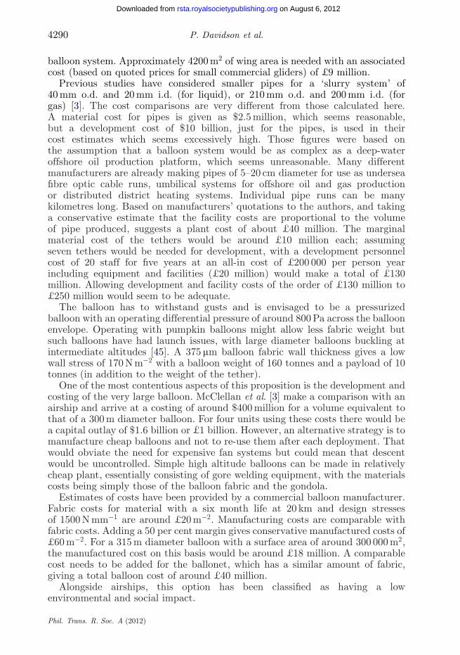
4290 P. Davidson et al.
balloon system. Approximately 4200 m2 of wing area is needed with an associatedcost (based on quoted prices for small commercial gliders) of £9 million.
Previous studies have considered smaller pipes for a ‘slurry system’ of40 mm o.d. and 20 mm i.d. (for liquid), or 210 mm o.d. and 200 mm i.d. (forgas) [3]. The cost comparisons are very different from those calculated here.A material cost for pipes is given as $2.5 million, which seems reasonable,but a development cost of $10 billion, just for the pipes, is used in theircost estimates which seems excessively high. Those figures were based onthe assumption that a balloon system would be as complex as a deep-wateroffshore oil production platform, which seems unreasonable. Many differentmanufacturers are already making pipes of 5–20 cm diameter for use as underseafibre optic cable runs, umbilical systems for offshore oil and gas productionor distributed district heating systems. Individual pipe runs can be manykilometres long. Based on manufacturers’ quotations to the authors, and takinga conservative estimate that the facility costs are proportional to the volumeof pipe produced, suggests a plant cost of about £40 million. The marginalmaterial cost of the tethers would be around £10 million each; assumingseven tethers would be needed for development, with a development personnelcost of 20 staff for five years at an all-in cost of £200 000 per person yearincluding equipment and facilities (£20 million) would make a total of £130million. Allowing development and facility costs of the order of £130 million to£250 million would seem to be adequate.
The balloon has to withstand gusts and is envisaged to be a pressurizedballoon with an operating differential pressure of around 800 Pa across the balloonenvelope. Operating with pumpkin balloons might allow less fabric weight butsuch balloons have had launch issues, with large diameter balloons buckling atintermediate altitudes [45]. A 375 mm balloon fabric wall thickness gives a lowwall stress of 170 N m−2 with a balloon weight of 160 tonnes and a payload of 10tonnes (in addition to the weight of the tether).
One of the most contentious aspects of this proposition is the development andcosting of the very large balloon. McClellan et al. [3] make a comparison with anairship and arrive at a costing of around $400 million for a volume equivalent tothat of a 300 m diameter balloon. For four units using these costs there would bea capital outlay of $1.6 billion or £1 billion. However, an alternative strategy is tomanufacture cheap balloons and not to re-use them after each deployment. Thatwould obviate the need for expensive fan systems but could mean that descentwould be uncontrolled. Simple high altitude balloons can be made in relativelycheap plant, essentially consisting of gore welding equipment, with the materialscosts being simply those of the balloon fabric and the gondola.
Estimates of costs have been provided by a commercial balloon manufacturer.Fabric costs for material with a six month life at 20 km and design stressesof 1500 N mm−1 are around £20 m−2. Manufacturing costs are comparable withfabric costs. Adding a 50 per cent margin gives conservative manufactured costs of£60 m−2. For a 315 m diameter balloon with a surface area of around 300 000 m2,the manufactured cost on this basis would be around £18 million. A comparablecost needs to be added for the ballonet, which has a similar amount of fabric,giving a total balloon cost of around £40 million.
Alongside airships, this option has been classified as having a lowenvironmental and social impact.
Phil. Trans. R. Soc. A (2012)
on August 6, 2012rsta.royalsocietypublishing.orgDownloaded from

Stratospheric aerosol geoengineering 4291
Table 2. Balloon system costs.
capital per balloon capital for four operating cost for four(million £) balloons (million £) balloons (million £ p.a.)
tethers 20 80 80lifting surfaces 10 40 20balloons 40 160 160pumps 50 200 30 maintenance +
200 electricityships/sites 100total 120 480 590
(i) Cost summary (excluding costs of aerosol and dispersal system)
The estimated costs for the balloon system are shown in table 2. It is assumedthat each balloon will operate for 7000 hours per year, giving an electrical powercost of about £50 million per year per balloon. It is assumed that the balloonand tether will be replaced each year and that annual pump maintenance willcost 15 per cent of the pump capital cost, and the cost of providing the ships andmaintaining the launch sites will be £100 million per year. Together these give atotal operating cost of about £600 million per year.
Development costs are likely to be less than four years’ costs of a singlestation if infrastructure costs (ships) and SO2 or particle generation facilitiesare excluded, leaving a total for capital + development costs of £600 million.Extended discussion on siting and legal/governance issues might increase theseto £700 million but this may be a significant overestimate given the inherentsimplicity of the design. Allowing between £700 million and £1000 million indevelopment costs would seem to be adequate.
Such a sum would buy the plant to produce the tethers (£40 million), seventethers (at £10 million each), seven assemblies of lifting devices (at £9 millioneach), seven large balloons (at £40 million each), a development, manufacturing,legal and management staff of 400 for 4 years (£320 million), and site facilitiesof £50 million.
If it were decided by a body, such as the Security Council of the UN, thatSRM had to be introduced as a matter of extreme urgency, it is believed thatthis could be done within a period of 5 years and is the basis of the data pointplotted in figure 8.
The facilities for manufacture of the tether already exist in the offshoreindustry, although some retooling would be necessary. Manufacturing facilitiesfor balloons larger than any built so far would need to be established, andthe balloons themselves tested, but this should just be a scale-up of existingtechnology. Parallel developments would need to be carried out for pumping andparticle dispersal.
A more measured approach would however be highly desirable and might bespread over a generation. It would allow refinements of climate modelling, testingof the albedo effects and of the atmospheric chemistry impacts of the particles.It would allow testing of the actual delivery systems, first at low level, then at20 km: in the first instance, nitrogen could be injected, followed later by injection
Phil. Trans. R. Soc. A (2012)
on August 6, 2012rsta.royalsocietypublishing.orgDownloaded from

4292 P. Davidson et al.
104
single-usemissiles
artillery
rigidtowers
coilguns
retrievablemissiles airships
aircraftsingle-useballoons
retrievable balloons
tethered balloons
103
102
10
1
net p
rese
nt c
ost (
£ bi
llion
)
10 1022 5 2 5
development time (yr)
Figure 8. Costs and development times (both on logarithmic scales) for various options, excludingcost of material to be dispersed. Costs are net present costs taking a 5% discount rate andamortizing over 10 years for the injection of 10 million tonnes p.a. into the stratosphere, to mitigatethe temperature effects of a doubling of CO2 levels.
of very limited amounts of particulate matter whose effects could be monitoredby ground-based, aerial or satellite observation. Only if these tests worked, andthen only if a supranational body such as the UN mandated the work, wouldprototype and production versions of the system be implemented.
Were it found necessary to implement SRM climate remediation then theauthors estimate that the research, development and governance process maytake about 20 years with perhaps another 10–15 years for implementation innormal conditions. The basis for this estimate along with estimates of costs foreach stage of the process are given in appendix A. These estimates are necessarilyvery approximate given the uncertainties of future global climate, economicsand politics.
Appendix A shows an outline science and technology roadmap for developingnot only the delivery technology but also the particle science and technology,the modelling of effect and some broad brush dialogue, communication, andgovernance issues. It should be noted that the cost estimates are dominated bythe particle material costs if a manufactured particle (such as titanium dioxide)is used. These would be the same for all systems.
This delivery method has four main developmental issues:
— the size of the balloon (significantly larger than the world’s largest balloonto date, which had a diameter of 120 m),
— the manufacture of a reliable high pressure tether,
Phil. Trans. R. Soc. A (2012)
on August 6, 2012rsta.royalsocietypublishing.orgDownloaded from

Stratospheric aerosol geoengineering 4293
— the need to ensure that no transient oscillations or dynamics compromisethe integrity of the system, and
— the need to scale up pumping technology.
It is believed, however, that all of these factors, although challenging, are at theedge of existing technology in one or more fields and can be overcome with suitabledevelopment resource. Consideration is being given to the possibility of usingan aerodynamically shaped tether. Allowing for imperfections of manufacture,the drag coefficient for an aerodynamic tether would typically be a third to afifth of that for a circular tether. Since the design case for the balloon is thatit must generate enough lift to prevent blow-over by the wind forces on thetether, an aerodynamic tether with intermittent lifting surfaces has the potentialto significantly reduce the size of the balloon by a factor of 2–3 in diameter.However, each balloon would then only support a smaller pipe so more balloons(by a factor of 15–20 times) would be needed. Such a design would allow smallerscale tests to be carried out more readily. A stratospheric injection system witheighty 125 m diameter balloons rather than four 315 m balloons could be envisagedfor a full-scale system. The total tether and balloon fabric weights for the twosystems would be comparable.
4. Comparing aerosol delivery technologies
It is now possible to compare the various options for delivering aerosols to thestratosphere. Table 3 shows a comparison of the systems discussed above in purelyfinancial terms; the costs are taken from the discussion made earlier and then a netpresent cost has been calculated for establishing each technology and operatingit for 10 years, taking a discount rate of 5 per cent. Allowing for differences inthe injection rate, the costs show good agreement with McClellan et al. [3] forthe more limited number of technologies considered in that work, except for thetethered balloon. This difference can be explained by the much larger developmentcosts suggested there, and the greater number of balloon systems.
Table 4 shows non-financial aspects, including the time needed to set upthe facility.
Figure 8 shows the time and cost data together.Rigid towers are extremely expensive mainly because of their very high initial
cost, although their running costs would be low. And uniquely among theoptions they could allow manned access to a permanent dispersal facility athigh altitude.
Single-use missiles, artillery and coilguns are all expensive, primarily because ofthe cost of the expendable delivery systems. It might well be possible, especiallyfor coilguns where the accelerations during launch can be kept fairly modest, forthe costs to be brought down if the delivery systems could be made to returnautonomously to a landing facility.
Most of the other systems cluster around the middle of the figure, with theexception of the tethered balloon concept. It is worth reflecting on whythis system is so cheap to ensure that no important factor is missing fromthe analysis.
Phil. Trans. R. Soc. A (2012)
on August 6, 2012rsta.royalsocietypublishing.orgDownloaded from

4294 P. Davidson et al.
Table 3. Summary of delivery technology costs. The initial procurement cost refers to the purchaseprice of capital necessary to begin delivery. In the case of technologies that involve fleets of deliveryvehicles (e.g. planes, retrievable balloons, retrievable missiles) the cost of purchasing the initial fleetis taken. Single-use vehicles have procurement costs factored into operating cost. The net presentcost is computed assuming a discount rate of 5% and covering a period of 10 years.
annual operating cost net presenttechnology initial procurement cost (excluding particle costs) cost (£billion)
single-use balloons facilities + infrastructure £7 billion 55retrievable balloons facilities + infrastructure +
£1 billion£9 billion 70
tethered balloons ships + facilities + £0.7billion development andinitial setup costs
£600 million 5
rigid towers £2000 billion for 4 towers 400 MW pumpingpower = £350 million
2003
50 : 50 fast jets/tankers fleet of 500 fast jets + 65tanker planes £17 billion
£11 billion 101
artillery 460 guns = £1 billion +facilities + infrastructure
£204 billion 1576
single-use missiles low £200 billion 1544retrievable missiles £20 billion £25 billion 213coilguns £2 billion £80 billion 619airships £80 billion £11 billion 165
— The connection between the ground and the stratosphere, althoughpermanent, is in tension and thus will tend to straighten, whereas thetower is in compression and tends to buckle. The lift for the supportingstructure comes free, from the natural buoyancy of helium or hydrogen.
— Only the material to be dispensed at high altitude has to be lifted, and thisis done by pumps at ground level. There are no casings to be manufactured,lifted, discarded or recovered.
— The accelerations during launch, pumping and recovery are all small, whichmeans that the system can be made from lightweight materials.
All of these factors, taken together, mean that the system has the potential tohave very much lower operating costs than the alternatives.
There is an additional advantage in that the system would remain in placemore or less continuously. Unlike systems that have to dispense their payloadin a very short time, the dispensing system can operate semi-continuously, andwould not get thrown away after every shot. This opens the way to improvingboth the effectiveness of the dispersion techniques, and also the choice of particlesto be dispensed.
5. Conclusion
There may be arguments against SRM of any kind, for instance that it doesnot directly retard ocean acidification, and there may be arguments against
Phil. Trans. R. Soc. A (2012)
on August 6, 2012rsta.royalsocietypublishing.orgDownloaded from

Stratospheric aerosol geoengineering 4295
Table 4. Estimates of non-financial criteria. It should be noted that this is a summary forcomparison purposes only.
minimumdevelopment environmental
technology time at altitude time (years) impact social impact
single-use balloons hours 5 high moderateretrievable balloons hours 8 moderate moderatetethered balloons continuous 5 low lowrigid towers continuous 50 medium moderateaircraft hours 5 high moderatenaval artillery seconds 10 moderate moderatesingle-use missiles minutes 5 high moderateretrievable missiles minutes 10 moderate moderatecoilguns seconds 15 moderate lowairships hours 15 low low
geoengineering itself. But while it is desirable that we work on reducing carbonemissions now, it would be prudent to have emergency systems in reserve as aninsurance policy. We should design the emergency mechanism before we need it,so that it can be tested to make sure that it is safe to use.
After considering the various options for SRM by stratospheric particleinjection, we suggest that a tethered balloon supporting a pressurized pipe islikely to be efficient, practical, controllable and much cheaper than any probablealternative.
A tethered balloon system might be used to deliver SRM, not just as anemergency measure, but also as part of a well-moderated and thoughtful processof climate control.
Peter Davidson is employed by Davidson Technology Limited which has a patent applicationpending regarding SRM technologies. Hugh Hunt and Chris Burgoyne are employed by theUniversity of Cambridge. They provided consultancy services for Davidson Technology Limitedin 2009, in their personal capacities, and were named as inventors on the patent application.All ownership and rights in the patent application reside with Davidson Technology Limited.Hugh Hunt and Chris Burgoyne are currently working on the SPICE project at the Universityof Cambridge which is funded by EPSRC and NERC. Matt Causier is a research student at theUniversity of Cambridge also working on the SPICE project.
The work described here was partly funded by the Engineering and Physical Sciences ResearchCouncil, the Natural Environment Research Council and Davidson Technology. The authors wouldlike to thank Tony Cox and Francis Pope (University of Cambridge), who provided input on thechemistry of the stratosphere, Don Grainger and Dan Peters (Universities of Oxford and Bristol),and John Temperley (Huntsman Tioxide) who provided input on scattering. In addition, PeterBraesicke and Richard McMahon (University of Cambridge), Matt Watson (University of Bristol),Olivier Boucher and Jim Haywood (Met Office) and Lesley Gray (University of Oxford) providedwind data and helpful comments on early versions of this paper. Hilary Costello and Kirsty Kuo(University of Cambridge) have also provided background work on balloon and tether dynamics,and with Jonathan Cooper (University of Liverpool) measurements of aerodynamic tether drag.David Loew (University of Cambridge) carried out calculations on some of the comparative systems.
Phil. Trans. R. Soc. A (2012)
on August 6, 2012rsta.royalsocietypublishing.orgDownloaded from

4296 P. Davidson et al.
Appendix A. An outline science and technology roadmap for SRMclimate remediation
1. Laboratory and concept development 3 years £2–3 million. Modelling ofclimate at approximately 50 km horizontal cell size.
(a) Explore the potential feasibility of managing ozone destructionprocesses in laboratory experiments, particularly by keeping N2O5 andchlorate surface reactions to a minimum.
(b) Demonstrate coating technologies in the laboratory that allow thepotential to achieve coatings that are stable for 3 years, that arenon-toxic and allow for 6000 bar slurrying and dispersion.
(c) Demonstrate light scattering in the laboratory by suitably dispersedparticles.
(d) Produce preliminary models of the impact on the flora and fauna ofmore diffuse light.
(e) Develop lower cost delivery technology: aerodynamic tether, vibrationmodel, pumping concepts.
(f) Carry out public engagement at a modest level:
(i) communicate and discuss the scale of the problem,(ii) discuss the concept of research to minimize the risk that we may
have to carry out a ‘panic implementation’,(iii) discuss the need to have a reversible intervention, and(iv) discuss the strengths and weaknesses of the moral hazard
argument.
(g) Examine the advantages and drawbacks of pre-made particulates incomparison with those created by slow hydrolysis of sulphates.
(h) Consider mechanisms that allow incremental testing of effect ratherthan a step change approach.
(i) Initiate a scientific, engineering and social debate on modellingneeds and pace of implementation with a wide variety ofstakeholders. Encourage dialogue with governments and non-governmental organizations including environmental groups.
(j) Develop scale-up and testing scenarios, and initiate discussion onwhat tests need international agreement, e.g. would tests notresulting in measureable ground illumination or precipitation changesover inhabited areas or areas of special scientific interest beroutinely accepted?
2. Pre-trial development: injection of 100 tonne p.a. nitrogen at 20 kmaltitude: approximately 3 years £6–10 million.
(a) Test pumping concepts, stabilization of tether, aerostat, launch andrecovery steps.
(b) Develop modelling scenarios: computing power, measurement andscience fundamentals.
Phil. Trans. R. Soc. A (2012)
on August 6, 2012rsta.royalsocietypublishing.orgDownloaded from

Stratospheric aerosol geoengineering 4297
(c) Continue laboratory work on phase 1 science + measurementtechniques for operation off 20 km platforms and identify othermonitoring technologies suitable for observing the microphysicsof plumes.
(d) Begin dialogue with UN to establish mandate for micro- and small-scaletests, governance and legal structure.
(e) Obtain buy-in to research from some mainstream environmentalorganizations: consider options to protect biodiversity.
3. Micro trials at 20 km of 0.01 per cent full scale: 100 tonne p.a. or 2 tonneper week approximately 3 years £40–80 million, approximately £10–20million p.a.
(a) Develop mandate for small-scale tests.
(b) Establish a climate remediation R&D centre on an ocean island withUN support, relatively near the equator.
(c) Test delivery technology, dispersion and pumping technology at amodest scale using a 150 000 m3 aerostat.
(d) Check atmospheric chemistry and opacity of plume, approximately50 miles downstream, with balloons, satellites and aircraft; continuelaboratory R&D and development work.
(e) Check coating stability, local weather effects.
(f) Demonstrate a variety of observation technologies from 20 kmplatforms.
(g) Computer model at approximately 10 times the resolution of 2011capability with approximately 7 km horizontal cell size.
(h) Reaffirm environmental buy-in with preliminary field results. Furtherdialogue with disparate communities.
4. Mini tests at 20 km. One per cent full scale (10 000 tonne p.a. or 200 tonneper week): approximately 6 years £80 million p.a.
(a) With UN support, test effect of plume to 500–2000 miles lengths overoceans: atmospheric chemistry, solar scattering, precipitation.
(b) Implement five 20 km altitude sampling points and three base stations.
(c) Monitor impact on a baseline series of ‘most sensitive areas’, e.g. SouthAsian monsoon, Sahel and Amazonian precipitation.
(d) Examine precipitation and vegetative impacts as well as microbiologyunder plume.
5. Five per cent scale at 20 km. 50 000 tonne p.a. £200 million p.a.approximately 6 years.
(a) With UN support, increase to just-detectable effects over whole planet.
(b) Monitor ozone levels and regional precipitation.
(c) Modelling to 100 times the resolution of current capability (approx.500 m resolution).
Phil. Trans. R. Soc. A (2012)
on August 6, 2012rsta.royalsocietypublishing.orgDownloaded from

4298 P. Davidson et al.
6. Implementation only if mandated by UN Security Council. Allow four yearsto build facilities and then ramp up full implementation in 10 years. Costapproximately £500 million p.a. at the start, rising to £3 billion p.a. atthe end (2011 prices) for complete scaled-up system, including the costof a manufactured particle such as 1 Mt p.a. titanium dioxide (approx.15% of current world production rates). It is assumed that costs of TiO2are comparable to 2011 prices (around £2000 per tonne), but they couldbe lower because of the scale of the operation or higher because of anincreased demand. At a rate of 2.5 Mt p.a., titanium dioxide costs wouldincrease to £6–7 billion p.a. and would account for around 25 per cent ofworld titanium dioxide production but it is hoped that these rates wouldnot be needed.
References
1 Shepherd, J. et al. 2009 Geoengineering the climate: science, governance and uncertainty. RoyalSociety Policy Document 10/09. London, UK: Royal Society.
2 Blackstock, J. J., Battisti, D. S., Caldeira, K., Eardley, D. M., Katz, J. I., Keith, D. W.,Patrinos, A. A. N., Schrag, D. P., Socolow, R. H. & Koonin, S. E. 2009 Climate engineeringresponses to climate emergencies. (http://arxiv.org/abs/0907.5140)
3 McClellan, J., Sisco, J., Suarez, B. & Keogh, G. 2010 Aurora Flight Sciences Corporationgeoengineering cost analysis final report, no. AR10-182, prepared under contract to theUniversity of Calgary.
4 Robock, A., Marquardt, A. B., Kravitz, B. & Stenchikov, G. 2009 The benefits, risks, and costsof stratospheric geoengineering. Geophys. Res. Lett. 36, L19703. (doi:10.1029/2009GL039209)
5 Committee on Science Engineering and Public Policy (COSEPUP). 1992 Geoengineeringoptions, appendix Q. In Policy implications of greenhouse warming: mitigation, adaptation,and the science base, pp. 433–464. Washington, DC: National Academies Press.
6 Davidson, P., Hunt, H. E. M. & Burgoyne, C. J. 2011 Atmospheric delivery system. Patentapplication no. GB 2476518.
7 Archer, D. et al. 2009 Atmospheric lifetime of fossil fuel carbon dioxide. Annu. Rev. EarthPlanet. Sci. 37, 117–134. (doi:10.1146/annurev.earth.031208.100206)
8 Teller, E., Wood, L. & Hyde, R. 1997 Global warming and ice ages: prospects for physicsbased modulation of global change. UCRL-JC-128157, Livermore National Laboratory,Livermore, CA.
9 Keith, D. W. 2009 Photophoretic levitation of engineered aersols for geoengineering. Proc. NatlAcad. Sci. USA 107, 16 428–16 431. (doi:10.1073/pnas.1009519107)
10 Katz, J. I. 2010 Stratospheric albedo modification. Energy Environ. Sci. 3, 1634–1644.(doi:10.1039/C00244ID).
11 Barksdale, J. 1966 Titanium: its occurrence, chemistry and technology, 2nd edn. New York, NY:The Ronald Press Company.
12 Pope, F. P., Braesicke, P., Grainger, R. G., Kalberer, M., Watson, I. M., Davidson, P. J. &Cox, R. A. In press. Properties and impact of stratospheric aerosol particles proposed for solarradiation management. Nature. (doi:10.1038/nclimate1528)
13 Haywood, J. M. et al. 2010 Observations of the eruption of the Sarychev volcano and simulationsusing the HadGEM2 climate model. J. Geophys. Res. 115, D21212. (doi:10.1029/2010JD014447)
14 Deshler, T., Liley, G. B., Bodeker, G., Matthews, W. A. & Hofmann, D. J. 1997 Stratosphericaerosol following Pinatubo, comparison of the north and south mid latitudes using in situmeasurements. Adv. Space Res. 20, 2057–2061. (doi:10.1016/S0273-1177(97)00595-4)
15 Guo, S., Bluth, G., Rose, W., Watson, I. M. & Prata, A. 2004 Re-evaluation of SO2 release ofthe 15 June 1991 Pinatubo eruption using ultraviolet and infrared satellite sensors. Geochem.Geophys. Geosyst. 5, Q04001. (doi:10.1029/2003GC000654)
Phil. Trans. R. Soc. A (2012)
on August 6, 2012rsta.royalsocietypublishing.orgDownloaded from

Stratospheric aerosol geoengineering 4299
16 Lambert, A., Grainger, R. G., Remedios, J. J., Rodgers, C. D., Corney, M. & Taylor, F. W.1993 Measurement of the evolution of the Mt. Pinatubo aerosol cloud by ISAMS. Geophys.Res. Lett. 20, 1287–1290. (doi:10.1029/93GL00827)
17 Pierce, J. R., Weisenstein, D. K., Heckendorn, P., Peter, T. & Keith, D. W. 2010 Efficientformation of stratospheric aerosol for climate engineering by emission of condensable vaporfrom aircraft. Geophys. Res. Lett. 37, L18805. (doi:10.1029/2010GL043975)
18 Rasch, P. P. 2008 Exploring the geoengineering of climate using stratospheric sulfate aerosols:the role of particle size. Geophys. Res. Lett. 35, L02809. (doi:10.1029/2007GL032179)
19 Wigley, T. M. 2006 A combined mitigation/geoengineering approach to climate stabilization.Science 314, 452–454. (doi:10.1126/science.1131728)
20 Bluth, G. J. S., Rose, W. I., Sprod, I. E. & Krueger, A. J. 1997 Stratospheric loading of sulfurfrom explosive volcanic eruptions. J. Geol. 105, 671–684. (doi:10.1086/515972)
21 Berrisford, P., Dee, D., Fielding, K., Fuentes, M., Kallberg, P., Kobayashi, S. & Uppala, S.2009 The ERA-interim archive. ERA Report Series Number 1, ECMWF.
22 Endlich, R. M., Solot, S. B. & Thur, H. B. 1955 The mean vertical structure of the jet stream.Tellus 7, 308–313. (doi:10.1111/j.2153-3490.1955.tb01167.x)
23 Rose, K. & Steinbüchel, A. 2005 Biodegradation of natural rubber and related compounds:recent insights into a hardly understood catabolic capability of microorganisms. Appl. Environ.Microbiol. 71, 2803–2812. (doi:10.1128/AEM.71.6.2803–2812.2005)
24 Joshi, M. M. & Jones, G. S. 2009 The climatic effects of the direct injection of watervapour into the stratosphere by large volcanic eruptions. Atmos. Chem. Phys. 9, 6109–6118.(doi:10.5194/acp-9-6109-2009)
25 Smitherman Jr, D. V. 2000 Space elevators: an advanced Earth-space infrastructure forthe new millennium. Report NASA/CP-2000-210429, NASA Marshall Space Flight Center,Huntsville, USA.
26 Tritton, D. J. 1988 Physical fluid dynamics, 2nd edn. Oxford, UK: Oxford University Press.27 Timoshenko, S. P. & Gere, J. M. 1961 Theory of elastic stability. New York, NY: McGraw-Hill.28 Bolonkin, A. A. 2007 Optimal rigid space tower. In Proc. 45th Aerospace Science Meeting,
Reno, Nevada, 8–11 January 2007, AIAA-2007-367.29 Krinker, M. 2010 Review of new concepts, ideas and innovations in space towers.
(http://arxiv.org/abs/1002.2405)30 Irvine, H. M. 1981 Cable structures. Cambridge, MA: MIT Press.31 Kiureghian, A. & Sackman, J. L. 2005 Tangent geometric stiffness of inclined cables under
self-weight. J. Struct. Eng. 131, 941–945. (doi:10.1061/(ASCE)0733-9445(2005)131:6(941))32 Gimsing, N. J. 1997 Cable supported bridges. New York, NY: Wiley.33 Quine, B. M., Seth, R. K. & Zhu, Z. H. 2009 A free-standing space elevator structure: a
practical alternative to the space tether. Acta Astronaut. 65, 365–375. (doi:10.1016/j.actaastro.2009.02.018)
34 Buxton, I. 2008 Big gun monitors: the history of the design, construction and operation of theRoyal Navy’s monitors. Barnsley, UK: Seaforth Publishing.
35 National Materials Advisory Board. 2010 Selling the nation’s helium reserve. Committee onUnderstanding the Impact of Selling the Helium Reserve; National Materials Advisory Board;National Research Council.
36 Chan, A. K., Hyde, R. A., Myhrvold, N. P., Tegreene, C. T. & Wood, L. L. 2008 High altitudeatmospheric alteration system and method. US Patent application no. 11/788383.
37 Badesha, S. S., Euler, A. J. & Schroeder, L. D. 1996 Very high altitude tethered balloonparametric sensitivity study. In Proc. 34th AIAA Aerospace Science Meeting, Reno, NV, 15–18January 1996, AIAA-1996-0579.
38 Redi, S., Aglietti, G. S., Tatnall, A. R. L. & Markvart, T. 2011 Dynamic response to turbulenceof tethered lighter than air platforms. AIAA J. Aircraft 48, 540–552. (doi:10.2514/1.53522)
39 Aglietti, G. S. 2009 Dynamic response of a high-altitude tethered balloon system. J. Aircraft 46,2032–2040. (doi:10.2514/1.43332)
40 Badesha, S. S. & Bunn, J. C. 2002 Dynamic simulation of high altitude tethered balloonsystem subject to thunderstorm windfield. In Proc. AIAA Atmospheric Flight Mechanics Conf.,Monterey, CA, 5–8 August 2002, AIAA-2002-4614.
Phil. Trans. R. Soc. A (2012)
on August 6, 2012rsta.royalsocietypublishing.orgDownloaded from

4300 P. Davidson et al.
41 Badesha, S. S., Euler, A. J. & Schroeder, L. D. 1996 Very high altitude tethered balloontrajectory simulation. In Proc. AIAA Atmospheric Flight Mechanics Conf., San Diego, CA,29–31 July 1996, AIAA-1996-3440.
42 Giannopoulos, I. P. & Burgoyne, C. J. 2009 Stress limits for aramid fibres. Proc. Inst. Civ. Eng.Struct. Build. 162/SB4, 221–232. (doi:10.1680/stbu.2009.162.4.221)
43 Kitagawa, T., Ishitobi, M. & Yabuki, K. 2000 An analysis of deformation process on poly-p-phenylenebenzobisoxazole fiber and a structural study of the new high-modulus type PBOHM+ fiber. J. Polym. Sci. B: Polym. Phys. 38, 1605–1611. (doi:10.1002/(SICI)1099-0488(20000615)38:12<1605::AID-POLB50>3.0.CO;2-Z)
44 Al-Mayah, A., Soudki, K. & Plumtree, A. 2006 Development and assessment of a newCFRP rod–anchor system for prestressed concrete. Appl. Compos. Mater. 13, 321–334.(doi:10.1007/s10443-006-9019-6)
45 Pagitz, M. & Pellegrino, S. 2007 Buckling pressure of ‘pumpkin’ balloons. Int. J. Solids Struct.44, 6963–6986. (doi:10.1016/j.ijsolstr.2007.03.021)
Phil. Trans. R. Soc. A (2012)
on August 6, 2012rsta.royalsocietypublishing.orgDownloaded from